

ENGLISH
p. 3
FRANCAIS p. 31
DEUTSCH p. 63
NEDERLANDS p. 63
ESPANOL
p.127
ITALIANO
p. 159
Warmtepomp
Bomba de Calor
alore
UltraTemp®E
Heat Pump
Pompe à Chaleur
Wärmepumpe
Pompa di C
Installation Guide
Guide de l’installation
Bedienungsanleitung
Installatiehandleiding
Guia de instalacion
Guide all’installazione
IMPORTANT SAFE TY INSTRUCTIONS
READ AND FOLLOW ALL INSTRUCTIONS
SAVE THESE INSTRUCTIONS
P-INSB-ULTP (Rev. Feb 2014)

2 UltraTemp®-E

Customer service
ENG
LISH
HERENTALS , BELGIUM (8:30 A.M. to 4:30 P.M.) CET
Website: www.pentairpooleurope.com
Declaration of Conformity
This declaration applies to Ultratemp-E 8 p/n 460990
Ultratemp-E 10 p/n 460991
Ultratemp-E12 p/n 460992
Ultratemp-E 15 p/n 460993
Standards used for showing compliance with the essential requirements
in the directive 2006/42/EC:
• Electromagnetic compatibility: 2004/108/EC
• Safety requirements for low voltage equipment: 2006/95/EC
• Pressure Equipment: 97/23/CE
• Noise production: 200/14/CE
• Harmonized standards: EN 60335.1,2.40
The manufacturer, Pentair has the right to modify the products without previous notice for as far as their
characteristics are not really changed by this.
© 2014 Pentair. All rights reserved
This document is subject to change without notice. Trademarks and disclaimers: IntelliFlo®, IntelliPool®,
UltraTemp-E®, and Pentair are trademarks and/or registered trademarks of Pentair and/or its affiliated companies.
Unless noted, names and brands of others that may be used in this document are not used to indicate an affiliation or
endorsement between the proprietors of these names and brands and Pentair. Those names and brands may be the
trademarks of those parties or others.
3
Contents
TI
AND SHUTDOWN
Important Safety Information ..................................................................................................................................... 4
Before Installing the Heat Pump ................................................................................................................................. 6
Installation and Location ............................................................................................................................................ 7
Electrical Connections and Wiring .............................................................................................................................. 9
Operating the Heat Pump ..........................................................................................................................................12
Heat Pump Control Panel Overview ..........................................................................................................................12
Setting up your ultratemp-E ......................................................................................................................................20
Maintenance .............................................................................................................................................................21
Technical Information ................................................................................................................................................23
Important Safety Information
This guide provides installation and operation instructions for the UltraTemp-E® Heat Pump. Consult Pentair with any
questions regarding this equipment.
Attention Installer: This guide contains important information about the installation, operation and safe use of
this product. This information should be given to the owner and/or operator of this equipment after
installation or left on or near the heat pump.
Attention User: This manual contains important information that will help you in operating and maintaining
this heat pump. Please retain it for future reference.
Before installing this product, read and follow all warning notices and instructions which are included. Failure to follow
the instructions in this manual may result in serious adverse health effects, or even serious or fatal injury. Failure to
follow the instructions in this manual will in all cases invalidate all guarantees and liability on the part of the
manufacturer.
Codes and Standards
All Pentair heat pumps must be installed in accordance with the local building and installation codes .
RISK OF ELECTRICAL SHOCK OR ELECTROCUTION.
The electrical supply to this product must be installed by a licensed, certified electrician or qualified personnel in
accordance with all applicable local codes and ordinances. Improper installation will create an electrical hazard which
could result in death or serious injury to pool or spa users, installers, or others due to electrical shock, and may also
cause damage to property. Read and follow the specific instructions inside this guide.
Do NOT attempt any internal adjustments inside the heater.
1. Keep your hands and hair clear of the fan blades to avoid injury.
2. If you are not familiar with your pool filtering system and heater:
a. Do NOT attempt to adjust or service without consulting your dealer, professional pool or air conditioning
contractor.
b. Read the entire Installation & User’s Guide before attempting to use, service or adjust the heater or pool filtering
system.
4 UltraTemp®-E
Consumer Information and Safety
ENG
LISH
The UltraTemp-E®- series of heat pumps are designed and manufactured to provide safe and reliable service when
installed, operated and maintained according to the information in this manual and the installation codes referred to
in later sections. Throughout the manual, safety warnings and cautions are identified by the “ “ symbol. Be sure to
read and comply with all of the warnings and cautions.
Elevated water temperature can be hazardous.
See below for water temperature guidelines before setting temperature.
1 Spa or hot tub water temperatures should never exceed 40°C (104° F). A temperature of 38°C (100° F) is
considered safe for a healthy adult. Special caution is suggested for young children. Prolonged immersion in hot
water can induce hyperthermia.
2 Drinking of alcoholic beverages before or during spa or hot tub use can cause drowsiness which could lead to
unconsciousness and subsequently result in drowning.
3 Pregnant women beware! Soaking in water above 38°C (100° F) can cause fetal damage during the first three
months of pregnancy (which may result in the birth of a brain-damaged or deformed child).
4 Before entering the spa or hot tub, the user should check the water temperature with an accurate thermometer.
Spa or hot tub thermostats may err in regulating water temperatures.
5 Persons with a medical history of heart disease, circulatory problems, diabetes or blood pressure problems should
obtain their physician’s advice before using spas or hot tubs.
6 Persons taking medication which induce drowsiness, such as tranquilizers, antihistamines or anticoagulants should
not use spas or hot tubs.
Hyperthermia occurs when the internal temperature of the body reaches a level several degrees above normal
body temperature of 37°C (98.6° F) The symptoms of hyperthermia include: drowsiness, lethargy, dizziness,
fainting, and an increase in the internal temperature of the body.
The effects of hyperthermia include:
1 Unawareness of impending danger.
2 Failure to perceive heat.
3 Failure to recognize the need to leave the spa.
4 Physical inability to exit the spa.
5 Fetal damage in pregnant women.
6
Unconsciousness resulting in danger of drowning.
The UltraTemp-E® is designed for outdoor use only
Do not permit children to use this product.
Warranty Information
Heat pumps are sold with a limited factory warranty. Details are specified in our product catalogue. Make all warranty
claims to an authorized Pentair dealer or directly to the factory. Claims must include the heat pump serial number and
model (this information can be found on the rating plate), installation date, and name of the installer. Shipping costs
are not included in the warranty coverage. This warranty does not cover damage caused by improper assembly,
installation, operation, improper water chemistry balancing or other chemical abuse, or improper sanitation
application, winterizing, field modification, or failure to earth bond and properly ground the unit. Any changes to the
heat pump, evaporator, heat exchanger, wiring, or improper installation may void the warranty.
5

Before Installing the Heat Pump
Heat Pump Overview
Your Pentair heat pump will provide you with years of heated pool enjoyment. Heat pumps operate by taking heat
from the surrounding air and transferring it into the water. The warmer the air and the more humidity in the air, the
more latent heat is available for heating your pool. With a properly sized heat pump for your pool, the heat pump
should raise your pool on average 1° C per 6 hour depending on air temperature, humidity, and water temperature.
The ideal or rated condition for the heat pump is 26° C air temperature, 80% relative humidity, and 26° C water
temperature. As conditions decrease from 80/80/80, the heat pump performance will decrease slightly.
Heat Pumps are best utilized to maintain a set water temperature; they are not intended to provide instant or fast
heating. It is not reasonable to expect a heat pump to perform like a conventional heater which has a much higher
output and faster response. Also, conventional heaters are not dependent on environmental conditions. Swimming
pool heat pumps are very similar to home heating and air conditioning heat pumps and therefore should be treated
similarly.
Proper operation and use of the heat pump is to set it at your desired temperature and leave it. Your heat pump will
turn on and off automatically to maintain your desired temperature much like your home air conditioning unit. To
take advantage of the sun’s energy, operate your heat pump during the heat of the day.
Your heat pump will still operate when the temperature drops at night, but the output will be decreased. It is
acceptable to shut the heat pump off and not use it for extended periods of time. When you have a need to heat your
pool, please plan accordingly since it may take the heat pump days to heat your pool back to your desired
temperature, depending on your pool temperature and environmental conditions.
Heat Pump Installation Requirements
Correct installation is required to assure safe operation. The requirements for Pentair heat pumps include the
following:
• Dimensions for critical connections.
• Field assembly (if required).
• Appropriate site location and clearances
• Proper electrical wiring
• Adequate water flow
This manual provides the information needed to meet these requirements. Review all application and installation
procedures completely before continuing the installation.
General Features
• Dual digital thermostats offer precise temperature control to maintain the desired separate water temperatures in
pool/spa combinations without overheating or wasting energy.
• Long-life corrosion resistant composite plastic cabinet stands up to severe climates and pool chemicals.
• 100% pure titanium heat exchanger assures corrosion-free performance for extra long life.
• Self-diagnostic control panel monitors and troubleshoots heat pump operations to ensure safe, dependable
operation.
• Autoset (time clock over-ride) feature monitors water temperature and turns the water circulation pump on and off
as needed to maintain desired pool temperatures.
• Automatic defrost feature senses refrigerant temperature and prevents the heat pump from freezing, allowing the
heat pump to operate at even lower temperatures.
• Compatible with all automated control packages using the pool/spa remote input. RS485 communication compatible
with IntelliPool automation enabling remote diagnosis and e-mail alert.
• Elevated base pan for positive drainage of condensation.
• 50mm plumbing connections for easy installation.
• Separate isolated electrical compartment prevents internal corrosion, extends heater life.
• Adjustable timer allows to set the heat pump to run for a predetermined time. Incremental by 10 minutes to a
maximum of 99 hours.
6 UltraTemp®-E
Installation and Location
Respect
safety distance between the pool and the heatpump (electric appliance) as required by
ENG
LISH
When pool equipment is located below the pool surface, a leak from any component can cause large
scale water loss or flooding. Pentair cannot be responsible for such water loss or flooding which may
cause damage to the product. Avoid placing the heat pump in locations where it can cause damage by
water or condensate leakage. If this is not possible, provide a suitable drain pan to catch and divert any leakage.
Only a qualified service person should install the heat pump. Before installing this product, refer to the
Important Warning and Safety Instructions
Packaging
This appliance must be packed and stored vertically, as specified on the packing.
A horizontal storage, even if temporary, will damage the appliance.
All damage due to incorrect packing or storage,will not be taken under warranty
Pentair encourages its customers to keep the heat pump packaging (paperboard pack +
polystyrene + pallet) for the duration of the warranty period in case of a need to return the
appliance to the factory.
The manual, unions and anti-vibration spacers are packed underneath the top cover.
Materials Needed for Installation
The following items are needed and are to be supplied by the installer for all heat pump installations:
1. Plumbing connections (50mm).
2. Level surface for proper drainage.
3. Suitable electrical supply line. See rating plate on unit for electrical specifications. A junction box is not needed at
the heat pump; connections are made inside of the heat pump electrical compartment.
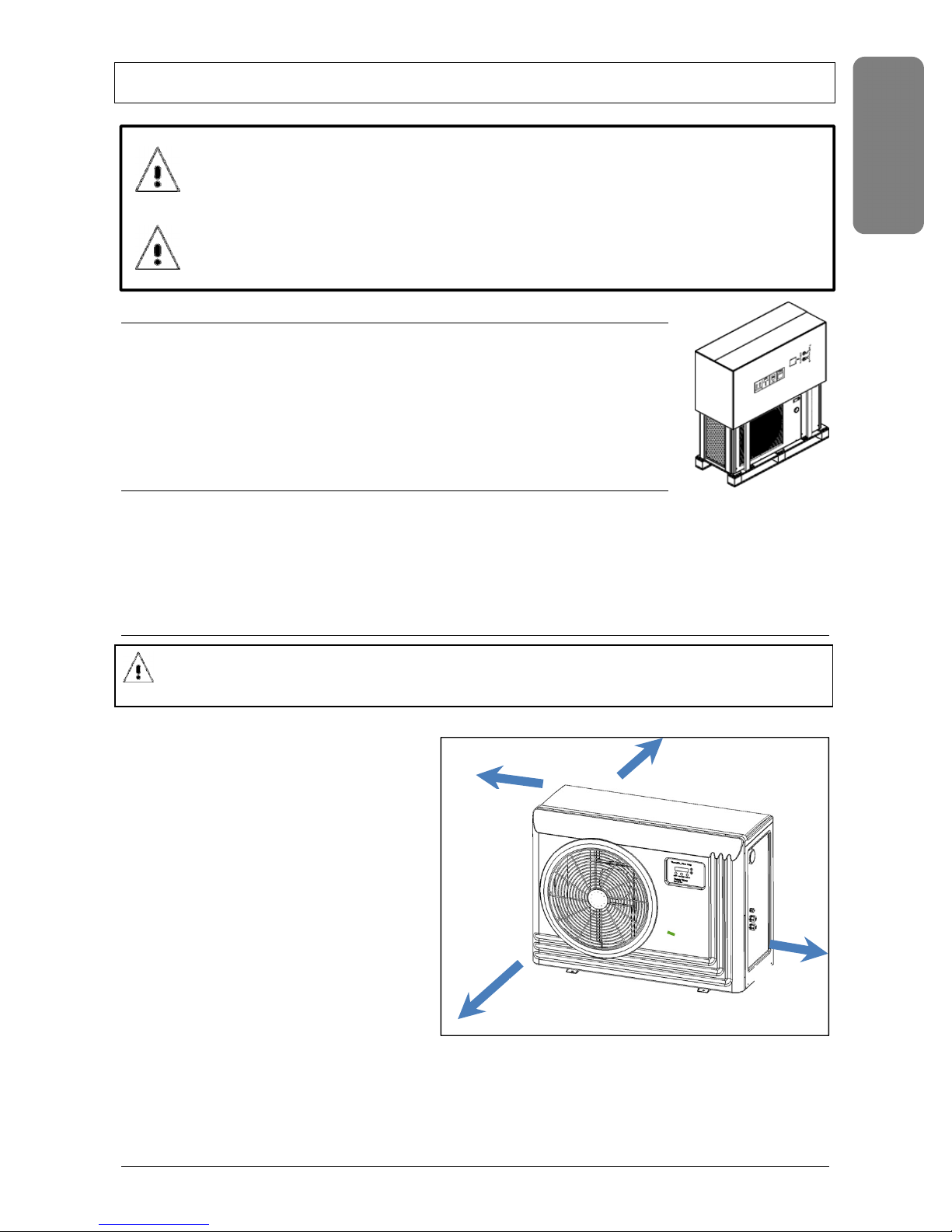
Installation location
local regulation
Maintain at least 1 m (40 ”) of space on the rear (evaporator air inlet ) and 3m (120 ”) on the outlet side of the fan on
a completely free space. Make sure that the
discharged air will not be sucked back into the
evaporator again.
1. Provide enough space to allow access to
temperature controller.
2. For proper drainage of condensation and rain
water, place the heat pump on a flat slightly
pitched surface, such as a concrete or
fabricated slab (pad).
3. If possible, place the pad at the same level or
slightly higher than the filter system
equipment pad.
4. Note: Be sure that the pad is pitched not more
than 1% in any direction as needed for runoff.
5. Mark the 4 fixation point on the equipment
pad (It is also possible to use the template
printed on the box)
6. Drill adequate holes for the fixation screws or anchor bolts. These screws should be at least 6mm diameter and
made of a corrosion resistant material.
7. Mount the heatpump on the rubber pads over the fixation holes.
8. Tighten the screws.
1 m
3 m
1 m
1 m
7
Avoid directing the flow of ventilated air towards a noise sensitive area (room window for example), or a space where
people normally gather (the discharged air will be cold)
Avoid positioning the pool heat pump on a surface that can transmit vibrations.
Try to avoid placing the appliance under a tree or exposed to water or mud, which would be likely to complicate
performance and maintenance
Drainage and Condensation
Condensation occurs from the evaporator coil while the unit is running, and drains at a steady rate (usually three to
five liters per hour), depending upon ambient air temperature and humidity. The more humid the ambient
conditions, the more condensation will be produced.
The bottom of the unit acts as a tray to catch rainwater and condensation. Keep the drain holes, located on the
bottom pan of the base of the unit, clear of debris. A plastic hose adapter is provided to allow controlled evacuation of
condensation
Roof Run Off
Make sure the heat pump is not located where large amounts of water may run-off from a roof into the unit.
Sharp sloping roofs without gutters will allow massive amounts of rain water, mixed with debris from the roof to be
forced through the unit. A gutter or down spout may be needed to protect the heat pump.
Lawn Sprinklers
Avoid placing lawn sprinkler near the heater - they can spray water into the heater and void the
warranty.
Be sure to direct any spraying water away from the heater. Note the wind direction to be sure water from
sprinklers is not blown toward the heater.
Sprinkler heads can produce high water pressure and spray at an angle, different from typical rain and humid
weather. Also, sprinklers connected to a well water system can cause mineral build up on the evaporator coils and
electronics. Salt water can also be an issue if located near the coast.
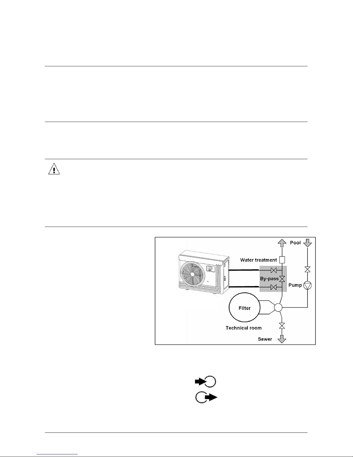
Water Connections to the Heat Pump
The heat pump should be connected to a
filtration circuit through a by-pass which
consists of 3 valves.
It is imperative that the by-pass is placed after
the pump and the filter.
These valves allow to regulate the water flow
which passes through the heat pump and to
isolate the heat pump completely for any
maintenance work, without cutting the
filtration flow.
If your installation is equipped with water
treatment devices (chlorine, brome feeder,
salt water chlorine generator, others) the bypass must be installed before the water
treatment devices, with a non-return check
valve between the by-pass and water treatment devices.
Water inlet and outlet are designed to be connected to rigid pressure PVC tube (for swimming pool) Ø50 mm, directly
glued to the half union connectors provided.
Inlet water tube must be connected to connection labeled:
Outlet water tube must be connected to connection labeled:
Water tubes must be fixed on the floor or the walls, so the heat pump will not support the weight of the water inside
the plumbing.
8 UltraTemp®-E
Electrical Connections and Wiring
ENG
LISH
RISK OF ELECTRICAL SHOCK OR ELECTROCUTION
This heat pump contains wiring that carries high voltage. Contact with these wires could result in death or serious
injury to pool or spa users, installers, or others due to electrical shock, and may also cause damage to property. Always
disconnect power circuit before connecting the heat pump
Label all wires prior to disconnection when servicing controls. Wiring errors can cause improper and dangerous operation.
Verify proper operation after servicing.
General Information
Wiring connections must be made exactly as shown in the wiring diagram found on the inside of the heat pump
access panel; see the wiring diagrams on next pages
The heat pump must include a definite means of grounding and bonding. There is a ground lug inside the heat pump
electrical compartment
The heat pump may be connected to an automation system via the remote pool/spa/com terminals in the wiring
compartment or via the RS-485 communication using the DT+/DT- terminals.
NOTE: Remote connection via the RS-485 connector is only available for IntelliPool software version V4.25 or higher.
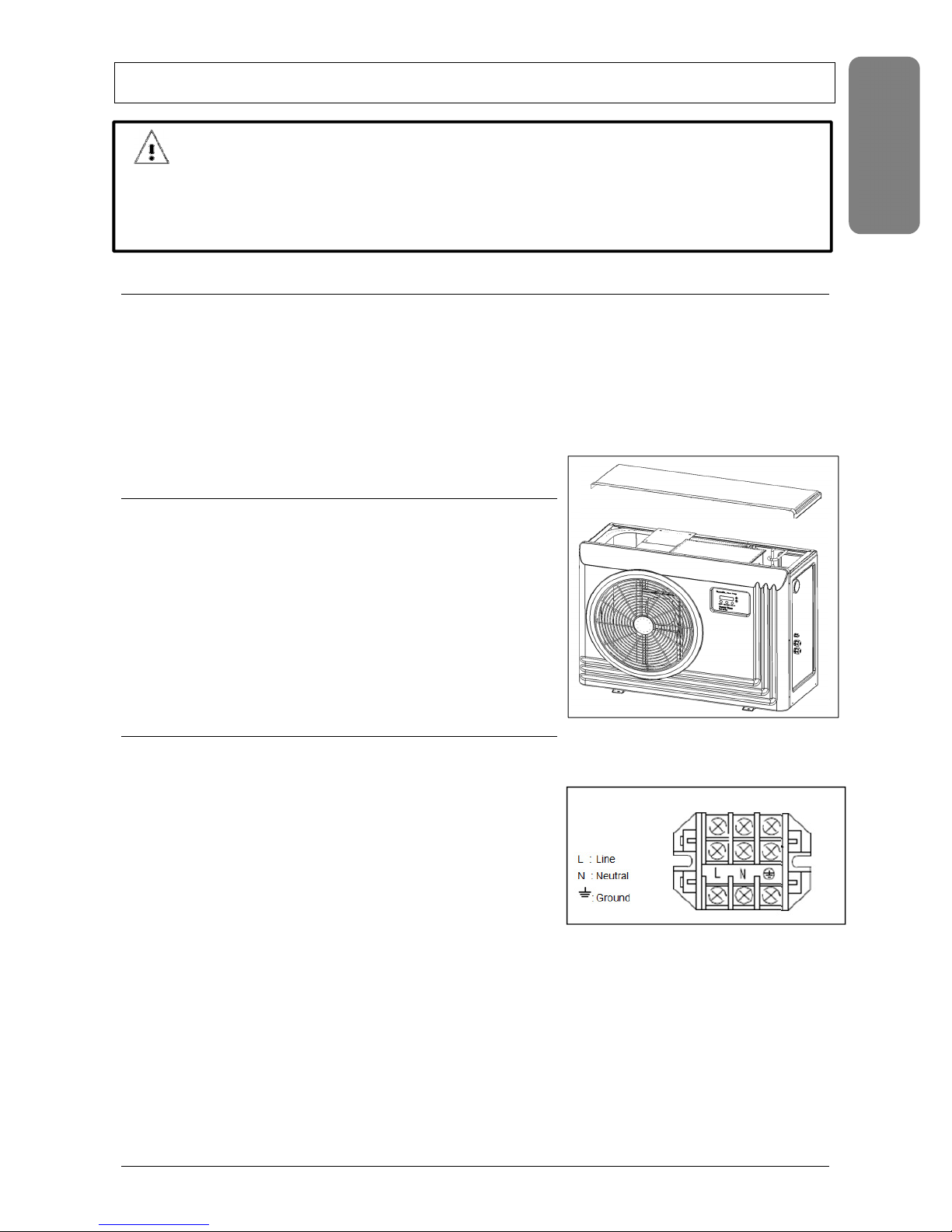
Accessing the Wiring compartment
Electrical wiring to the heat pump must be in accordance with local
codes and regulations.
1. Remove the top panel of the heat pump cabinet.
2. Remove the top panel of the wiring compartment.
3. Run the wires from the power source /remote and connect through
the cable glands on the right hand side of the heat pump and lead
them to the electrical compartment on top of the unit. Attach the
cable to the guide wire and gently pull the guide wire from inside the
wiring compartment . Dispose of the guide wire afterwards.
4. Replace the wiring compartment and heat pump top panel before
powering up.
Main Power
Electrical wiring to the heat pump must be in accordance with local codes and regulations.
Be sure the power to the circuit for the heat pump is turned off.
1. For cable and circuit breaker selection consult Technical data in the
back of this manual.
2. Access the wiring compartment
3. Connect 230V power supply on the terminal block in the wiring
compartment.
4. On first installation check all terminals on relays and connectors as
they may have loosened in transport
.
9
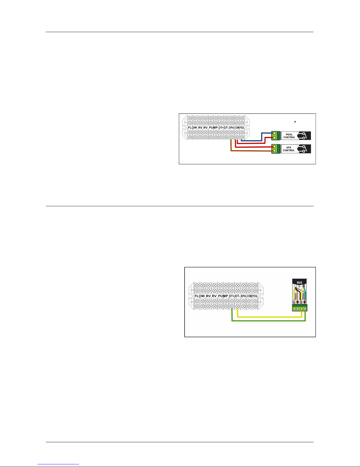
Relay Remote Controls
Electrical wiring must be in accordance with local regulations and codes.
Note: Heat pump control board set points will be disabled and shown as N/A. Temperature Setup is done using an
external thermostat controlled system.
To connect remote control equipment to the heat pump, perform the following steps:
Disconnect all power to the heat pump and control system.
1 Access the wiring compartment.
2 Run the wires from the pool/spa remote control system into the upper electrical compartment.
3 Connect the wiring from the pool/spa remote control system to the heat pump remote control terminals
Note: Do not apply voltage to the Spa/Pool /Com terminals. A dry contact is required !
4 Replace the electrical service panel.
5 Replace the top panel.
6 Restore power to the heat pump and the pool/spa
remote control system.
7 Press the Menu Select button repeatedly to scroll to
the Remote Control screen. Toggle the selection by
pressing one of the arrows until the screen displays
“Relay”.
8 Set the temperature of the pool/spa on your external thermostat controller. The temp settings on the Ultratemp-E
are not accessible when the “relay” remote Control function is selected on the heat pump
Connecting the Heat Pump to IntelliPool automation systems via the RS-485 Connector
The heat pump can be controlled by an IntelliPool®system via the RS-485 communication cable. In this configuration,
IntelliPool® overrides preset Temperature Set points on the heat pump and will start or stop the heat pump.
The transfer of this data takes several seconds and causes a delay from when the command is given from the
IntelliPool® control center until the heat pump physically responds. This happens automatically but may take 1-2
minutes to complete.
Note: Heat pump control board set points will be disabled and shown as N/A. Temperature Setup is done within the
IntelliPool system (setpoint menu). The heater can be activated in the Command Menu on internet or the
settings/temp menu on the control center.
Disconnect all power to the heat pump and control
system.
1. Access the wiring compartment.
2. Run a 2x0.5mm2 cable from the IntelliPool® data bus
into the heat pump wiring compartment. It is possible
to use excess IntelliFlo communication cable.
3. Connect the IntelliPool bus data + and – to the DT+
and DT- terminal inside the UltraTemp-E wiring
compartment.
The inputs are part of an RS485 interface.
Note: Do not apply voltage to the RS485 terminals
4. Replace the electrical service panel.
5. Replace the top panel.
6. Restore power to the heat pump and the pool/spa remote control system.
7. Press the Menu Select button repeatedly to scroll to the Remote Control screen. Toggle the selection by pressing
one of the arrows until the screen displays “RS485”. Set the temperature of the poo/spa on your IntelliPool
system. The temp settings on the Ultratemp-E are not accessible when the “relay” remote Control function is
selected. Switch on the heat pump.
10 UltraTemp®-E
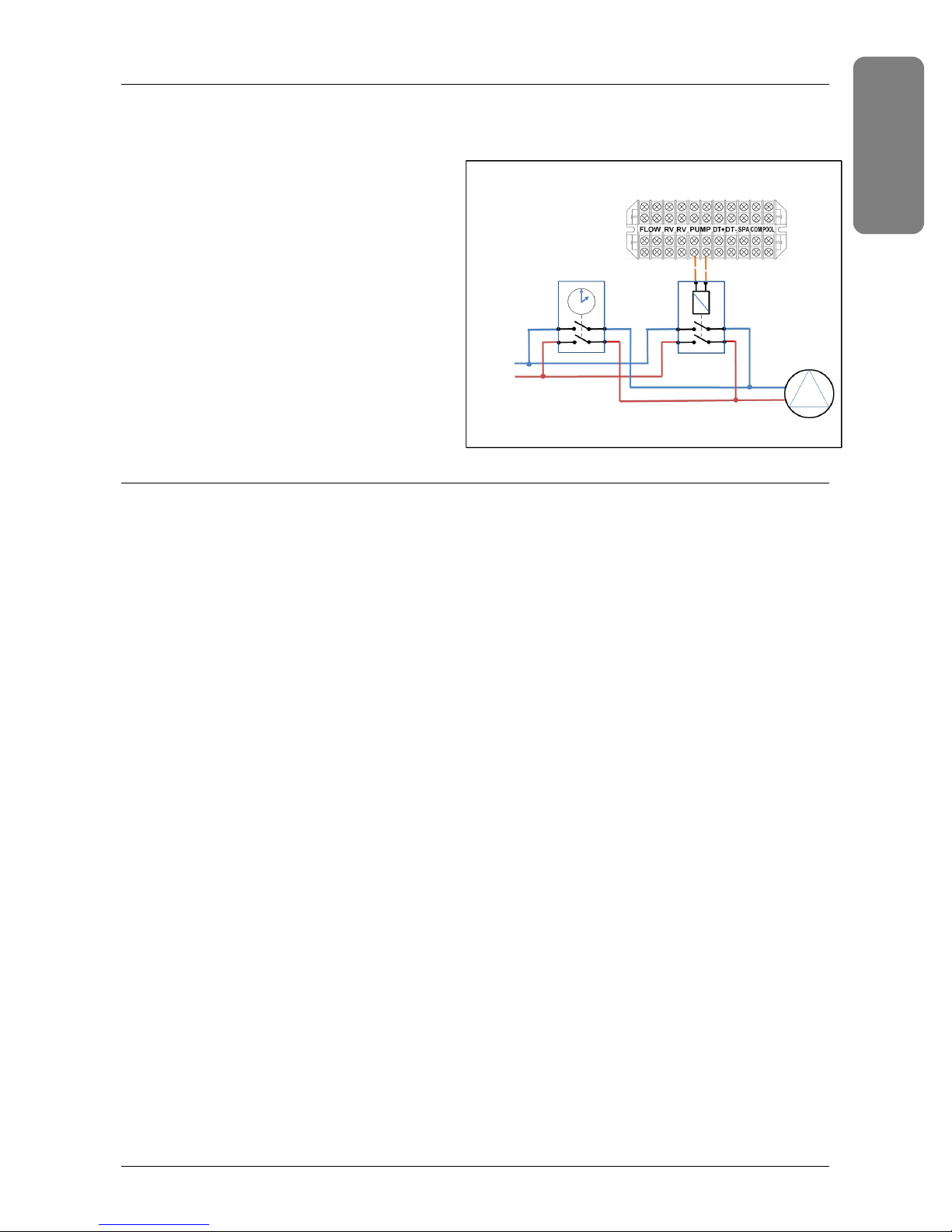
Connecting the Filtration Pump to the UltraTemp
24VAC
Timer contactor
Pump
230V
ENG
LISH
The heatpump can activate the filtration pump when the AUTOSET or EXTEND function are being used. These features
periodically energize a contactor which can be connected to the pump to move water through the heat pump.
Note: the contactors are not included with the heatpump.
1. Access the wiring compartment.
2. Run the wires from the pool/spa remote control
system into the upper electrical compartment.
Connect the ‘pump’ terminals on the main
terminal block to an external contactor. The
example below shows how to override a standard
pump timer.
Note: The contactor must be specified for 24 VAC
input. Make sure not to cross Neutral and Line
connections.
3. Replace the electrical service panel.
4. Replace the top panel.
5. Restore power to the heat pump and the filtration
pump.
N
L
Other terminals on the Terminal Block
1. FLOW Connects to the Flow switch (located on top of the heat exchanger)
2. RV Connects to the reversing Valve actuator
11
POOL IDLE °C
Operating the Heat Pump
Do not use this heat pump if any part has been under water. Immediately call a qualified service technician to inspect
the heater and replace any part of the control system which has been under water. Keep all objects off the top of the
heat pump. Blocking air flow could damage the unit and may void the warranty.
ATTENTION - INITIAL START UP PRECAUTIONS
After the water pressure switch is activated there is a one minute temperature sensing delay then if there is a call for
heat or cool the fan will turn on and there will be an additional 5 minute delay for the compressor to start. Be sure
that there is water in the pool and that the surface level is above the skimmer or other inlets of the pool’s filter
system.
The pool pump must be on and water flowing through the heat pump for it to operate.
With any new pool or spa installation, operate the filter pump with the heat pump off long enough to completely
clean the water. This will remove any installation residue from the water. Clean the filter at the end of this
operation before starting the heat pump. When raising the temperature of a cold pool, program the time clock to
run the pump continuously. This lets the filter system and heat pump operate continuously until the water reaches
the temperature setting on the temperature control. When that happens, the heat pump will automatically shut
off, but the filter pump will keep running.
Swimming Pool Energy Saving Tips
It is important to note that a heat pump will not heat a pool as fast as a large gas or electric pool heater. If the pool
water is allowed to cool significantly, it may take several days to return to the desired swimming temperature.
For weekend use, it is more economical to maintain the water temperature at or near the desired temperature. For
extended non-use, turn the heat pump completely off or decrease the temperature setting of the control several
degrees to minimize energy consumption.
Pentair offers the following recommendations to help conserve energy and minimize the cost of operating your heat
pump without sacrificing comfort.
1 Pentair strongly recommends the use of a pool cover. Besides providing a valuable safety feature, a pool cover will
reduce heat loss, conserve chemicals, and reduce the load on filter systems
2 Use an accurate pool thermometer. A difference of 2° C (4°F) , between 26° C. and 28° C. [78° F. and 82° F ], will
significantly increase energy consumption.
3 Carefully monitor the water temperature of your pool in the summertime.You can reduce heat pump usage due to
warmer air temperatures.
4 During the winter or when on vacation for longer than a week, turn off the heat pump.
5 Find the proper setting on the heat pump temperature control and use the Keypad Lock function to discourage
further adjustments.
6
Where possible, shelter the pool from prevailing winds with well-trimmed hedges or other landscaping, or
fencing..
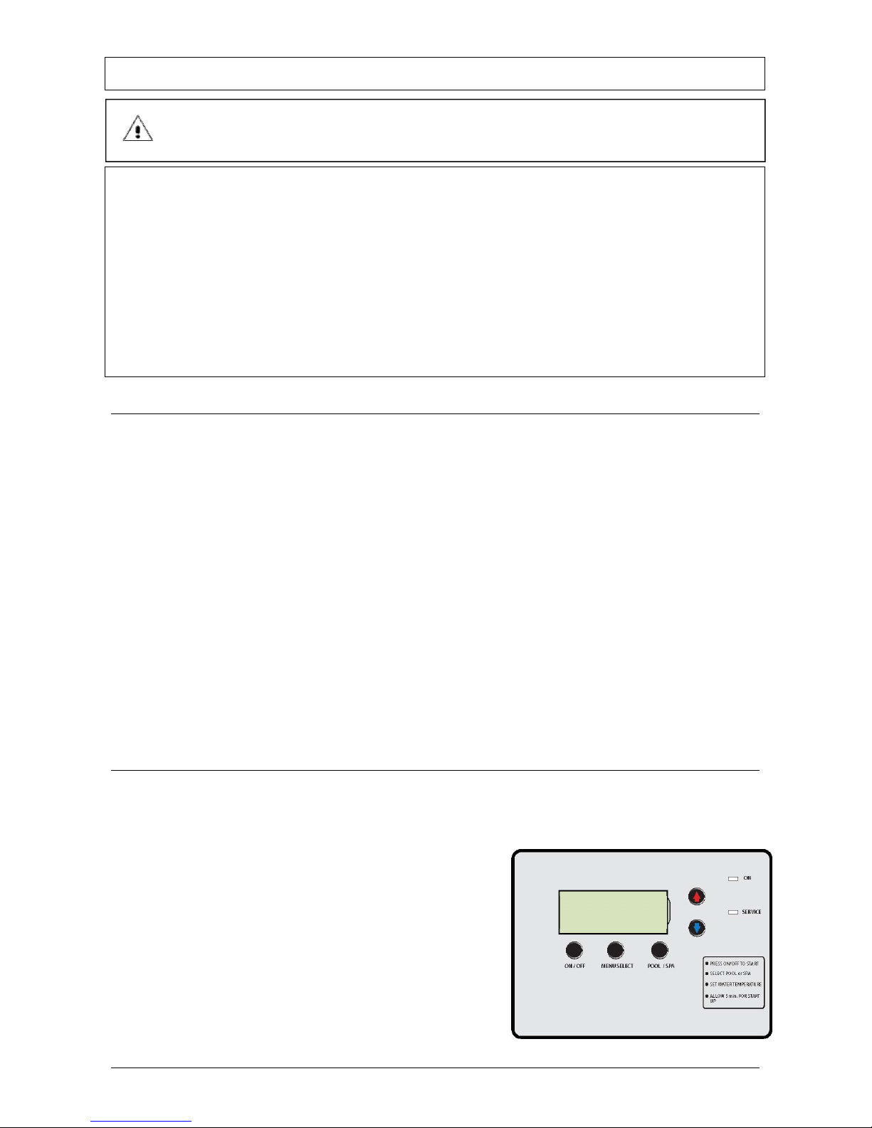
Heat Pump Control Panel Overview
1. ON/OFF button – Turns the heat pump On and Off.
2. MENU SELECT button – Displays Menu Select Screens; also used to scroll through the Operator Setup Menus
3. POOL/SPA button – If pressed once, the current heat, cool or auto mode will be displayed along with the active set
point, pool or spa.
Pressing again will toggle between the pool or spa set points screens.
The operator can also toggle between the pool and spa set point by
using the UP and DOWN arrows.
4. UP and DOWN Arrow buttons – The UP and DOWN arrows will raise
or lower the temperature set point if pressed while the run screen is
displayed. They are also used to scroll through the various parameter
values on the Menu Select and Operator Setup screens.
5. LCD SCREEN – Displays water temperature, set point temperature
and heat pump parameters.
6. ON Light – Shows the heat pump is on.
7. SERVICE Light – Lit if alarm condition exists.
The instructions in the lower right hand corner can be applied in other languages using a sticker supplied
SET = 24 ACT = 22
12 UltraTemp®-E
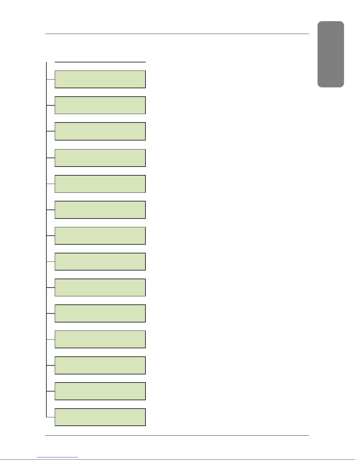
Operator Set Up Menu Tree Guide (Press UP and DOWN Arrows Simultaneously)
ENG
LISH
Navigating the Operator Set Up Screen
Press the Up and Down arrows simultaneously. If no activity is detected after 15 seconds, the display will return to the
main screen. Press the MENU SELECT button to view each screen
LANGUAGE/IDIOMA
SELECTED- ENGLISH
SOFTWARE VERSION
474788.BC
PUMP START TIME
TIME= 2 HRS
INTELL ADDRESS
ADDRESS= 1
START DELAY
TIME= 1 MIN
TEMP SCALE
FAHRENHEIT
WATERTEMP OFFSET
OFFSET= -2 C
DEFROST
ENABLED
AUTOSET
DISABLED
EXTEND
DISABLED
WF HP LP PL SP
1 1 1 0 0
FAN COMP PMP REV
0 1 0 1
RUN TIMES/COUNTS
↑
OR ↓ TO VIEW
PRESS POOL/SPA
1. Language
Select between English, French, German, Dutch, Spanish or
Italian.
2. Software Revision Displays the software revision level
loaded on the control board.
3. Pump Start Time This displays the period at which the
heat pump will close the AutoSet contactor to start the filter
pump. Adjustable from 0 to 5 hours using the UP and DOWN
arrows.
4. Intelli Address IntelliPool® RS-485 Communications
Address Should always be set to 1
5. Temperature Scale Determines if the water temperature
actual reading and set point is displayed in degrees
Fahrenheit or Celsius. Adjusted between Fahrenheit and
Celsius using the UP and DOWN arrows.
6. Watertemp Offset Adjusts the measured water
temperature up or down to allow the operator to match the
heat pump measured temperature to a remote temperature
monitoring device. The offset can be varied from -2 to +2
using the UP and DOWN arrows.
7. Defrost Screen Allows to Enable/Disable defrost cycle
using the UP and DOWN arrows
8. Autoset Allows to Enable/Disable the Autoset Function
using the UP and DOWN arrows
9. Extend Allows to Enable/Disable the Extend Function
using the UP and DOWN arrows
10. Input Screen The Input screen is a diagnostic display
which shows the status of the input sensors. The number 1 is
displayed when the associated input is on and zero is
displayed when the associated input is off. WF= Flowswitch,
HP = High pressure LP= Low pressure, PL= Pool remote and
SP = Spa remote
11. Output Screen The Output screen is a diagnostic display
which shows the status of the Output devices.The number 1
is displayed when the associated output is on and zero is
displayed when the associated output is off. FAN= Fan,
COMP= compressor, PMP= pump relay, REV= reversing valve
12. Run Times / Counters screen Use the up and down
arrow to scroll through an extensive list of log times and
counters for the main components of this heatpump. For
each of the outputs as well as the defrost function run times
and number of run cycles can be retrieved. The menu also
allows for a reset of the timers and counters. The ‘warranty’
times and counters cannot be reset and represent the heat
pumps total lifetime values
13. Exit Set Up Pressing the POOL/SPA button while this
screen is displayed returns the display to the Pool or Spa Run
Screen as appropriate.
TO EXIT SETUP
13
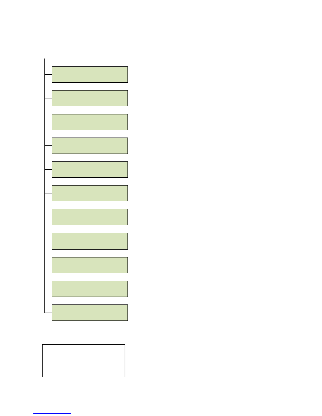
Control Panel Menu Tree Guide
sec of inactivity
(Press MENU SELECT Button)
Press the MENU SELECT button to view each screen. While in the menu screens, if no activity is detected after 15
seconds, the main screen is displayed.
1. Auto Mode Screen
HEAT MODE
POOL
POOL IDLE °C
SET= ACT=
SPA IDLE °C
SET= ACT=
HEAT/COOL/AUTO
SET TO- HEAT
HEATPUMP TIMER
REMAINING= 4:30
REMOTE MODE
OFF
AUTOSET HEAT
OVERRIDE IS OFF
EXTEND HEAT
OVERRIDE IS OFF
RESTART DELAY
REMAINING= 1:00
SUCTION TEMP
ACTUAL= 24°C
ALARM STATUS
NONE
*
Menu appears only if Autoset or Extend
is enabled at the factory.
**
Menu appears only if a delay is active
***
Display return to this view after 15
Displays whether the heat pump is in Heat only, Cool only or Auto
mode. It also displays whether the Pool or Spa set point is active. The
active set point can be switched between Pool and Spa by using the
UP and DOWN arrows.
2. Pool and Spa Run Screens
Displays whether the heat pump is idle, heating or cooling if the Pool
***
or Spa set point is active. Displays the water temperature set point
and the actual measured water temperature.
3. Heat or Cool Mode Selection Screen
This screen is only shown on Auto Heat and Cool heat pumps. This
screen allows the operator to switch the heat pump between heatonly, cool-only and auto heat/cool modes by using the UP and DOWN
arrows.
4. Heat Pump Timer Screen
This feature is an adjustable timer to allow the heat pump to run
(green LED ON) and then turn OFF (green LED OFF) for a
predetermined amount of time.
5. Relay Remote On/Off Screen
Allows the operator to turn the Relay Remote mode On and
Off. In Relay Remote mode, the heat pump is controlled by an
external thermostatic controller.
.Note: When using RS485 communication cable, the relay
remote must be turned off.
6. AutoSet On/Off Screen
*
This menu allows the operator to turn the AutoSet mode On and Off.
AutoSet mode periodically energizes a filter pump contactor to start
a remote filter pump which allows the heat pump to heat or cool the
*
water as necessary.
7. Extend On/Off Screen
This menu allows the operator to turn the Extend mode On and Off.
Extend mode will keep the filtration active until the SET temperature
**
is reached.
8.Time Delay Screen
If the heat pump is waiting on any restart, pump start, or sensing
water temperature delays, this screen shows how much delay time is
left.
9. Suction Temperature Screen
Shows the suction line temperature of the refrigerant. This screen
appears if the defrost is enabled.
10. Alarm Screen
Shows if an alarm condition is present. If no alarms are present the
screen will display ALARM STATUS NONE. The control board has the
ability to store a 30 Alarm history of previous alarms that have
occurred. At the alarm status screen, press the DOWN arrow. The
first alarm will be the most recent alarm that has occurred.
Successive presses (up to 30) of the DOWN arrow will display the
alarm history in the order of occurrence The operator can scroll back
up using the UP button. There is an option to erase the history.
14 UltraTemp®-E

Temperature Scale - C˚ or F˚
ENG
LISH
The control board can display temperatures in either degrees Fahrenheit or Celsius. The temperature scale in use can
be changed from the Operator Setup Menu Tree as described below:
1 Press the UP and DOWN arrows simultaneously. The Language Selection screen should be displayed.
2 Then press the MENU SELECT button repeatedly until the Temperature Scale screen is displayed.
3 Press the UP or DOWN arrows to toggle between the Fahrenheit and Celsius options. The last option shown on the
display will become active.
Water Temperature Offset
The control board provides the ability to increase or decrease the measured water temperature by 2 degrees.
To change the temperature offset:
1 Press the UP and DOWN arrows simultaneously.
2 Press the MENU SELECT button repeatedly until the Temperature Offset screen is displayed.
3 Press the UP or DOWN arrows to select the desired offset. The last number shown on the display will become
active.
Locking the Control Panel
Heat pump control panel lock-out – To prevent unwanted adjusting or manipulating of the heat pump settings, the
control panel can be locked. Once locked, if any button is pressed, the display will read:
HEAT PUMP
CONTROLS LOCKED
• To activate the control panel lockout, press the MENU SELECT and POOL/SPA buttons simultaneously.
• To unlock the control panel, press the MENU
SELECT and POOL/SPA buttons simultaneously.
Defrost Cycle
The heat pump may enter a defrost cycle if air temperatures are around 10° C (50° F).
The defrost cycle initiates when the evaporator sensor detects refrigerant temperature below the defrost set point.
At this time, the heat pump compressor stops. The heat pump evaporator fan will continue to run, and the reversing
valve is activated. This wil heat up and actively defrost the evaporator.
Note: as the evaporator is heated during defrost, production of water vapour might be observed as well as
increased production of condensation water .
If the temperature sensor detects a temperature above 7° C (44° F ), the compressor will restart after the 15 minutes.
If not, the unit will shut down.
The efficiency of a heat pump decreases as air temperature decreases. For maximum efficiency, operate the heat
pump during the warmest time of day.
Starting and Stopping the Heat Pump
The heat pump is started and stopped with the ON/ OFF button.
1 Starting - With power supplied to the heat pump, press the ON/OFF button to start the heat pump. The ON light
should be lit.
2 Stopping -Press the ON/OFF button to stop the heat pump; the ON light will turn off. The screen shown below will
be displayed temporarily.
PENTAIR AQUATICS
HEAT PUMP OFF
15

Changing the Set Point (Temperature)
The control board has 2 independently adjustable temperature set points. One is for the pool temperature control and
the other is for the spa temperature control. The active mode of operation (pool or spa) is defined as the “active” set
point.
1. Press the MENU SELECT button repeatedly until the associated run screen is displayed. Press the UP or DOWN
arrows to adjust the pool or spa temperature set point.
SET= ___ - Set point
ACT= ___ -Actual measured water temperature
2. The screen automatically returns to the active run screen after 15 seconds of keypad inactivity.
Heat Pump Timer
This feature is an adjustable timer to allow the heat pump to run (Green LED ON) and then turn OFF (Green LED OFF)
for a predetermined amount of time.
During the selected time frame, the green LED indicator is on and the heat pump functions in the normal mode of
operation. When the green led indicator turns off, the heat pump turns off when time expires. Countdown time is in
hours and minutes.
To activate the heat pump timer:
1. Press MENU SELECT repeatedly until the heat pump timer screen is displayed.
2. Press UP or DOWN arrows to set the amount of time (range of 10 minutes to 99 hours). Timer adjusts in
increments of 10 minutes.
3. If the heat pump is not already on, setting the timer will activate and start the heat pump.
4. The user can also change the time while it is active using the arrow buttons, only if Relay or Serial Remote
modes are OFF.Turning Relay ON disables the heat pump timer at the control panel.
5. Any RS-485 communication received will reset the timer to zero. The RS-485 overrides the heat pump timer
operation.
6. The timer can be disabled by pressing the DOWN arrow and POOL/SPA buttons at the same time, or by
pressing the ON/OFF button.
Relay Remote Control
In relay remote operation, the heat pump is started and stopped by remote relays which are connected to the remote
POOL, COMMON and SPA quick connect connectors on the main terminal block inside the wiring compartment.
When conductivity is provided between the pool and common connections or the spa and common connections, the
heat pump will start as long as these inputs are closed.The local set points are not active in relay remote operation.
In relay remote operation, the heat pump is made to start and stop via an external thermostat control. This means
the remote automation controls override the heat pump’s local set point.
However, the high and low temperature faults are still active; the heat pump will not heat above 40°C (104° F) or cool
below 7°C ( 45° F.)
To activate the relay Remote Mode: Press MENU SELECT repeatedly until the Relay Remote screen is displayed. Once
displayed, press the UP or DOWN arrows to toggle between ON and OFF
Serial Remote control (RS485 Cable) for IntelliPool
See the IntelliPool user’s manual for additional setup instructions.
When connected to IntelliPool an additional UltraTemp menu will show up on the Internet Interface. This menu will
show the heat pump alarm messages if they occur.
In serial remote operation, the heat pump is made to start and stop via a serial RS-485 communications link with an
IntelliPool controller. This means the remote automation controls override the heat pump’s local set point.
However, the high and low temperature faults are still active; the heat pump will not heat above 40°C (104° F) or cool
below 7°C ( 45° F.)
Note: When connected to the RS485 communication cable, the heat pump will not respond to commands from the
control panel display buttons except On/Off.
IntelliPool software version 4.25 or higher is required for UltraTemp functionality.
16 UltraTemp®-E

AutoSet
ENG
LISH
Enable this feature any time the filter pump is off. The AutoSet feature periodically energizes a contactor which can be
connected to the pump to move water through the heat pump. This allows the heat pump to sense the water
temperature.
If the temperature is not at the desired level, the heat pump starts, along with the filter pump, until the water reaches
the desired temperature. The filter pump and the heat pump will stop when the water reaches the desired
temperature.
AutoSet allows you to set intervals (1-4 hours) to control when the heat pump senses the water temperature. Use
AutoSet to maintain the desired pool water temperature.
To use this feature:
Be sure the water circulation pump is wired in parallel with a mechanical time clock, using an auxiliary (24VAC
powered) relay that should be connected to the ‘pump’ terminals on the main terminal block. (see installation
instructions on page 11 ).
To enable the AutoSet feature:
1 Press the MENU SELECT button repeatedly until the AutoSet screen is displayed.
2 Press the UP or DOWN arrows to toggle between the ENABLE and DISABLE options.
3 Set the interval (1-4 hours) from the control panel to control when the heat pump sends a signal to check the
water temperature.
For example, if you program the heat pump control board with a pump start time interval of 4 hours, have the AutoSet
feature enabled, and have a desired water temperature of 27°C (80° F ), this is the sequence of events that will happen:
1. The heat pump displays a countdown window after the filter pump shuts off.
2. After four (4) hours, heat pump will switch on and start the filter pump depending on the temperature set point.
3. The heat pump will sense water temperature then determine if it needs to continue to circulate water.
4. If the pool temperature has fallen below your set point, the heat pump will turn on and begin heating the pool. If
the pool temperature is above the set point, the heat pump and filter pump will shut off.
5. At the time the water circulation pump shuts off, the heat pump will reset and begin the countdown interval and
display ‘Pump Start Delay’ again.
6. Once the time clock turns on in the morning, the heat pump will stop the AutoSet feature and resume normal
operation.
Extend
This feature will extend the filtration pump timing until the set point is reached. To use this feature:
Be sure the water circulation pump is wired in parallel with a mechanical time clock, using an auxiliary (24VAC
powered) relay that should be connected to the ‘pump’ terminals on the main terminal block. (see installation
instructions on page 11 )
To enable the Extend feature:
1 Press the MENU SELECT button repeatedly until the Extend screen is displayed.
2 Press the UP or DOWN arrows to toggle between the ENABLE and DISABLE options.
3 When the set temperature is not reached when the normal filtration cycle stops, the heatpump will override the
timer and keep running water through the heatpump until the set temperature is reached.
17

Timers and Delays Control Panel Alarm Messages
Water Sensing Timer
One minute timer to allow water from the pool to reach the Heat Pump before acquiring temperature. This timer
initiates when water first begins to run from stopped or low water flow conditions or when the heat pump is turned
ON. Countdown time is in Minutes and Seconds.
Restart Delay Timer
Five minute timer is a protection feature for the heat pump’s compressor. This extends the life of the compressor’s by
not allowing it to cycle on and off (i.e. adjusting set point up and down around actual temperature). Countdown time
is in minutes and seconds.
Defrost Delay Timer
Fifteen minute timer where the heat pump is in Defrost operation. Countdown time is in minutes and seconds. Refer
to page 18 for more details on the defrost cycle.
Pump Start Delay
One to Four Hour timer used in conjunction with the AutoSet feature. Counts down the time until the control board
will energize the internal contactor in the heat pump to turn on. Countdown time is in hours and minutes. See AutoSet
section for more details.
Heat Pump Runtime Timer
This feature is an adjustable timer to allow the heat pump to run (Green LED ON) and then turn OFF (Green LED OFF)
for a predetermined amount of time. During the selected time frame the Green LED Indicator is ON and the heat
pump will function in the normal mode of operation and/or the operator can change set points, functions, etc. The
heat pump’s Green LED Indicator will turn OFF and the heat pump will stay OFF when time expires.
NOTE: It is possible to override Delay Times (for example to speed up servicing) by pushing the POOL/SPA and down
Arrow simultaneously
18 UltraTemp®-E
Alarm Messages
WATER THE
RM SHORT
Water temperature thermistor circuit shorted.
SERIAL COMM LOST
Problem with RS485 communication from IntelliPool
E
NG
LISH
The control board can display specific alarm conditions. The table below shows the potential alarm messages on the
display.
Press ON/OFF to reset an alarm.
HIGH WATER TEMP Water temperature is above 40°C
LOW WATER TEMP Water temperature is below 7°C
LOW WATER FLOW The switch sensing water flow is open.
REMOTE POOL SPA Pool and Spa relay remote inputs are simultaneously energized.
WATER THERM OPEN Water temperature thermistor circuit open.
SUCTION TH SHORT Defrost thermistor circuit shorted
SUCTION TH OPEN Defrost thermistor circuit open.
BROWNOUT The 24 VAC supply voltage to the control board is low.
HIGH REFRIG Refrigerant high pressure switch is open.
LOW REFRIG Refrigerant low pressure switch is open.
FIVE ALARMS
Indicates that 5 faults have occurred in one hour. This fault will automatically reset
in one hour or can be manually reset by pressing the ON/OFF button.
Timer/ Counter Menu messages
Within the service menu it is possible to access diagnostic data reflecting the runtimes and number of cycles that a
specific output has been activated. Press the Up and Down arrows simultaneously.. Press the MENU SELECT button
repeatedly until the display shows
RUN TIMES/COUNTS
↑
OR ↓ TO VIEW
Use the up and down arrows to display the different messages.
Press POOL/SPA to exit this menu.
COMP RUN TIME Displays current compressor runtime
COMP CYCLES Displays number of compressor cycles since last reset
COMP LOG TIME Displays total compressor runtime since last reset
FAN RUN TIME Displays current fan runtime
FAN CYCLES Displays number of fan cycles since last reset
FAN LOG TIME Displays total fan runtime since last reset
REV VLV RUN TIME Displays current reversing valve runtime
REV VLV CYCLES Displays number of reversing valve cycles since last reset
REV VLV LOG TIME Displays total reversing valve runtime since last reset
FLT PMP RUN TIME Displays current autoset/extend relay runtime
FLT PMP CYCLES Displays number of autoset/extend relay cycles since last reset
FLT PMP LOG TIME Displays total autoset/extend relay runtime since last reset
DEFROST RUN TIME Displays current defrost runtime
DEFROST CYCLES Displays number of defrost cycles since last reset
DEFROST LOG TIME Displays total defrost runtime since last reset
COMP WARRANTY Displays total compressor runtime (cannot be reset)
REV VLV WARRANTY Displays total reversing valve runtime (cannot be reset)
DEFROST WARRANTY Displays total defrost runtime (cannot be reset)
19

Setting up your ultratemp-E
Installation
After having connected the heat pump to the pool water circuit system trough a suitable by-pass and having made the
electrical connections by a qualified engineer, please verify the following points:
• Appliance is in a horizontal position and on a solid ground.
• Water circuit is primed (full of water): no air inside the
tubes or the heat pump tank.
• Water circuit is well connected (no leaks and no chance of
injury due to badly fitted hydraulic couplings).
• Electrical circuit is well connected (all cables tightened
correctly at terminals and intermediate circuit breaker),
insulated and earthed correctly.
• The installation requirements described previously are
strictly adhered to.
• Ambient temperature is between :+ 3 and + 35°C
• Water temperature is between 15 and 30°C
You can then start up your machine. Follow the instructions
below in the given order each time you start up the pool heat
pump, especially at the beginning of the swim season:
• Open the three by-pass valves and then half close the
settings valve
• Start the pool pump
• Turn on the pool heat pump with the on/off switch .
• Check the machine to make sure that it starts only together with the filtration pump: If the filtration pump is not
working, the “flow” LED will stop lighting. If it doesn’t detect any water flow, please see chapter an alarm will be
generated
• The pool heat pump will work after a delay of few minutes.
• Set the temperature using the up or down arrow.
• After a few minutes (time for circuit to heat itself) you can regulate water flow as explained hereafter (Chapter
“Water flow setting”)
Water flow setting
To optimize the performance of the heating process, it is advisable to regulate the water flow through the heat pump.
The adjustment must be carried out according to the indication given by the pressure gauge. The setting is modified
by opening or closing the setting valve of the by-pass.
To increase the pressure on the manometer (pressure gauge), the water flow passing through the heat pump must
decrease: Open the setting valve.
To decrease the pressure on the manometer (pressure gauge), the water flow passing through the heat pump must
increase: Close the setting valve.
For a normal working performance, inlet and outlet valves must be completely open.
Normal pressure
Pressure inside the refrigerant circuit of the heat pump and the water flow influence each other.
To work correctly, a water flow of 5 to 7 m³/h (100 l/min) should be maintained for maximum heat transfer.
If the value indicated on the pressure gauge is in the green area between 1,5 and 2,5, the water flow is CORRECT.
Set the water flow to 1,5 when water is cold (at the start of the season) and between 2 and 2,5 when water is about
28 to 30°C.
Warning: The Heat pump needs to operate for few minutes before the internal pressure stabilizes
Abnormal pressure
If the pressure is too high or too low, it indicates that the water flow circulating inside the heat pump is not correct.
You need to adjust the water flow by opening or closing the by-pass valve. Open little by little it if the pressure is too
low and close it little by little if the pressure is too high until it remains stable in the green area.
Pressure gauge must be between value 1 and 1,3 when the machine is stopped. If the value is 0, don’t start the
machine (contact your seller).
20 UltraTemp®-E

Maintenance
pH 7.4 to 7.6
Calcium Hardness (CH)
200 to 400 ppm
ENG
LISH
Water Chemistry
Proper chemical balances are necessary for sanitary bathing conditions as well as ensuring your heat pump’s long
life.
Be sure to keep your chemical and mineral concentration levels within the values indicated in the table below. Failure
to maintain proper water chemistry may cause damage to the heat pump and may void the warranty.
Test
Free Chlorine 1.0 to 3.0 ppm (3.0 to 5.0 spa)
2.0 to 4.0 ppm (3.0 to 5.0 spa)
Total Alkalinity (TA) Calcium, Lithium, and
Sodium Hydrochlorite
Total Alkalinity (TA) Sodium Dichlor,
Trichlor, Chlorine Gas
Cyanuric Acid 30 to 50 ppm **
Total Dissolved Solids (TDS) Less than 2000 ppm
Copper 0 ppm
* Concentration levels taken from “Basic Pool and Spa Technology” published by NSPI
(National Spa and Pool Institute).
** no cyanuric acid is allowed for systems using redox sensors like IntelliPool
Recommended Level
80 to 100 ppm
100-120 ppm
Winterizing
Failure to winterize could cause damage to the heat pump and will void the warranty
In areas where freezing temperatures occur, you should protect your pump, filter, and heat pump from the elements.
Perform the following steps to completely drain the heat pump.
1 Turn off the electrical power to the heat pump at the main breaker panel.
2 Shut off the water supply to the heat pump.
3 Disconnect the water inlet and outlet unions located on the rear panel of the heat pump.
4 Blow out the water lines.
5 Cover only the heat pump to prevent debris from falling into the unit. A winterizing cover is available as an
accessory (see spare part list on page 28)
Spring Start Up
If your heat pump has been winterized, perform the following steps when starting the system in the Spring:
1 Uncover the heat pump and inspect the top and sides for any debris or structural problems.
2 Connect the water inlet and outlet unions on the sides of the heat pump.
3 Turn on the filter pump to supply water to the heat pump. Open the filter air bleeder and circulate water through
the system long enough to bleed all the air out of the pool system. Check for leaks in and around the heat pump.
4 Turn on the electrical power to the heat pump at the main breaker panel.
Inspection and Service
Pentair Heat Pumps are designed and constructed to provide long performance life when installed and operated
properly under normal conditions.
Periodic inspections are important to keep your heat pump running safely and efficiently through the years. Failure
to properly maintain your unit can void the warranty.
21

Owner Inspection
Pentair recommends that you inspect your heat pump on a continual basis and especially after abnormal weather
conditions. The following basic guidelines are suggested for your inspection:
• Make sure the front of the unit is accessible for future service.
• Keep the rear and surrounding areas of the heat pump clear of all debris.
• Keep all plants trimmed and away from the heat pump.
• Keep lawn sprinkler heads from spraying on the heat pump to prevent corrosion and damage.
• If the unit is installed under a roof edge, install a gutter or diverter to prevent excessive water and debris from
pouring down into the unit.
• Do not use this heat pump if any part has been under water. Immediately call a qualified professional technician to
inspect the heat pump and replace any part of the control system which has been submerged.
The heat pump will produce condensation (water) while in operation. The heat pump base is designed to allow the
condensation to exit through the bottom drain port when the unit is running. The condensation will increase as the
outdoor air humidity level increases. Check the following at regular intervals to ensure proper condensate drainage:
1. Visually inspect and clear the bottom drain ports of any debris that could clog the ports.
2. Keep the top air flow discharge and air flow intake area clear of debris so the air flow through the heat pump is
not restricted. The cooler discharge air from the top should not accumulate and be drawn into the side air intake
coils.
3. Be sure the condensate run-off is properly directed away from the equipment pad to keep it from undermining
the pad.
4. Be sure the condensate water does not puddle inside the heat pump. To be sure it is condensate water, check for
the absence of chlorine.
During normal operation, the heat pump produces several liters of condensate per hour. If condensate drainage is
above this range during operation or if water continues to drain from the base when the heat pump is not in
operation for more than an hour, a leak in the internal plumbing may have occurred. Call a qualified heat pump
technician to investigate the problem.
The maximum heat output and efficiency of a heat pump is dependent upon the quality and performance of the major
components used. Equally important are the environmental conditions (for example, air temperature, humidity, water
temperature, and wind).
To maintain maximum performance and efficiency, keep the air coil clean from dirt and debris. It is recommended to
clean your air coil once a year by flushing the coil with compressed air or hosing off the coil with a garden hose.
Care should be taken to not bend the coil fins as this will restrict the airflow and lower your heat pump performance.
Compressed air can also damage the heat pump coil. DO NOT USE A PRESSURE CLEANER ON THE UNIT.
Professional Maintenance and Service
Preferably, the heat pump should be maintained at least once a year by qualified personnel to maintain maximum
performance and efficiency. The unit should be powered off during maintenance.
In case of a problem call your dealer. Pentair will assist your dealer in determining the cause of the problem and
solving the issue.
22 UltraTemp®-E
Technical Information
ENG
LISH
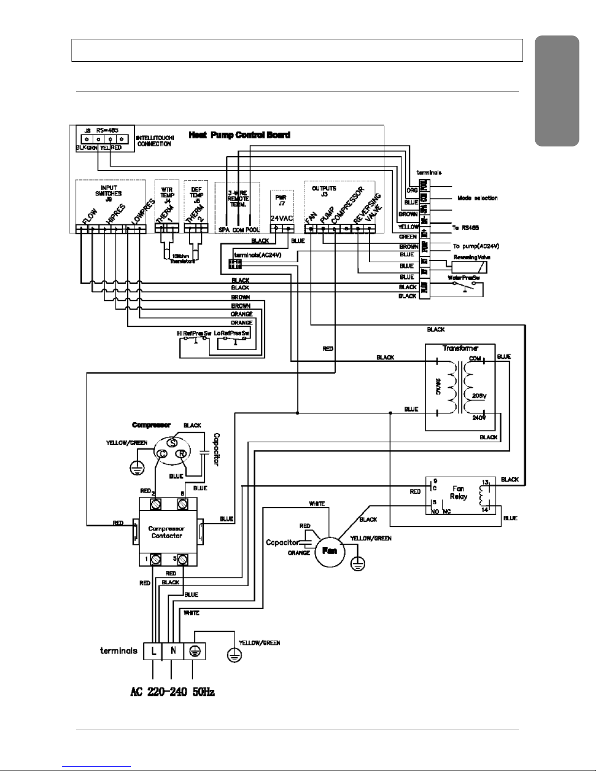
Wiring diagram Ultratemp-E 08, Ultratemp-E10 and Ultratemp-E 12
23
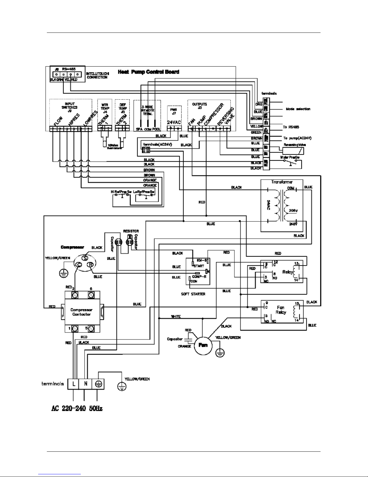
Wiring diagram Ultratemp-E 15
24 UltraTemp®-E

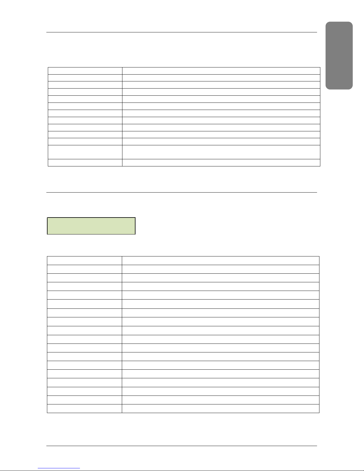
Performance data
15/°C
Model
Heating power
Power input W 1550 1960 2302 3009
COP - 5.3 5.2 5.4 5.3
Heating power
Power input W 1532 1996 2306 3021
COP - 4.7 4.8 4.9 4.8
Heating power
Power input W 1625 2078 2455 3104
COP - 5.2 5.1 5.3 5.2
Fan
Air
24°C 70%RH
Water
20°C
Air
70%RH
Water
26°C
Air
24°C 70°RH
Water
13°C
Speed RPM 900 900 800 800
Power W 80 80 140 140
W 8210 10190 12430 15950
W 7200 9100 11300 14500
W 8450 10600 13010 16140
ULTRATEMP-E 8 ULTRATEMP-E 10 ULTRATEMP-E 12 ULTRATEMP-E 15
Power supply 230V- 1~ - 50Hz
Minimum water flow m³/h 4 5 5 5
Noise level
COP = Coefficient of Performance
RH = Relative Humidity
A 1m 53 dB(a) 54 dB(a) 54 dB(a) 54 dB(a)
A 10m 33 dB(a) 34 dB (a) 34 dB(a) 34 dB(a)
25
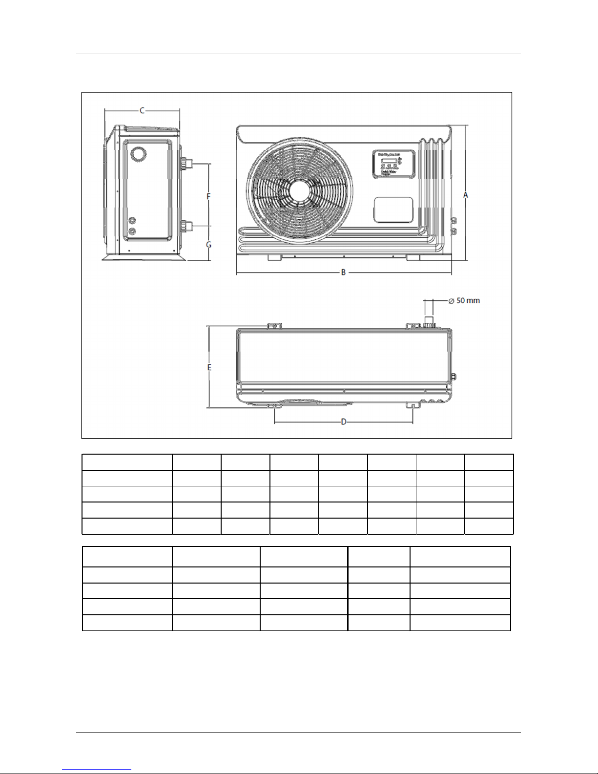
Dimensions & Weight
Pallet qty
Pallet LxBxH (mm)
Ultratemp
® E 8
57671
1120x420x760
Ultratemp
® E 10
70801
1120x420x760
Ultratemp
® E 12
90
10511140x490x885
Ultratemp
® E 15
115
13011140x490x885
Ultratemp
® E 8
632
1006
352
650
372
300
111
Ultratemp
® E 10
632
1006
352
650
372
300
111
Ultratemp
® E 12
762
1025
413
640
422
420
106
Ultratemp
® E 15
762
1025
413
640
422
470
106
Model A mm B mm C mm D mm E mm F mm G mm
Model
26 UltraTemp®-E
Net Weight (Kg) Gross weight (Kg)

Electrical connections
ENG
LISH
Electric supply voltage and current values must match the values indicated on the heat pump.
Connection cables must to be sized according to the appliance power and installation requirements.
Model Power supply
ULTRATEMP-E 08
ULTRATEMP-E 10
ULTRATEMP-E 12
ULTRATEMP-E 15
*Maximum cable length between heat pump and head of line protection
3G 230 V 16 A 20 m 30 m 40 m 70 m
3G 230 V 16 A 20 m 30 m 40 m 70 m
3G 230 V 20 A 10 m 20 m 30 m 50 m
3G 230 V 25 A - 20 m 30 m 50 m
Head of line
protection
Maximum cable length* for given section:
2,5 mm² 4 mm² 6 mm² 10 mm²
27
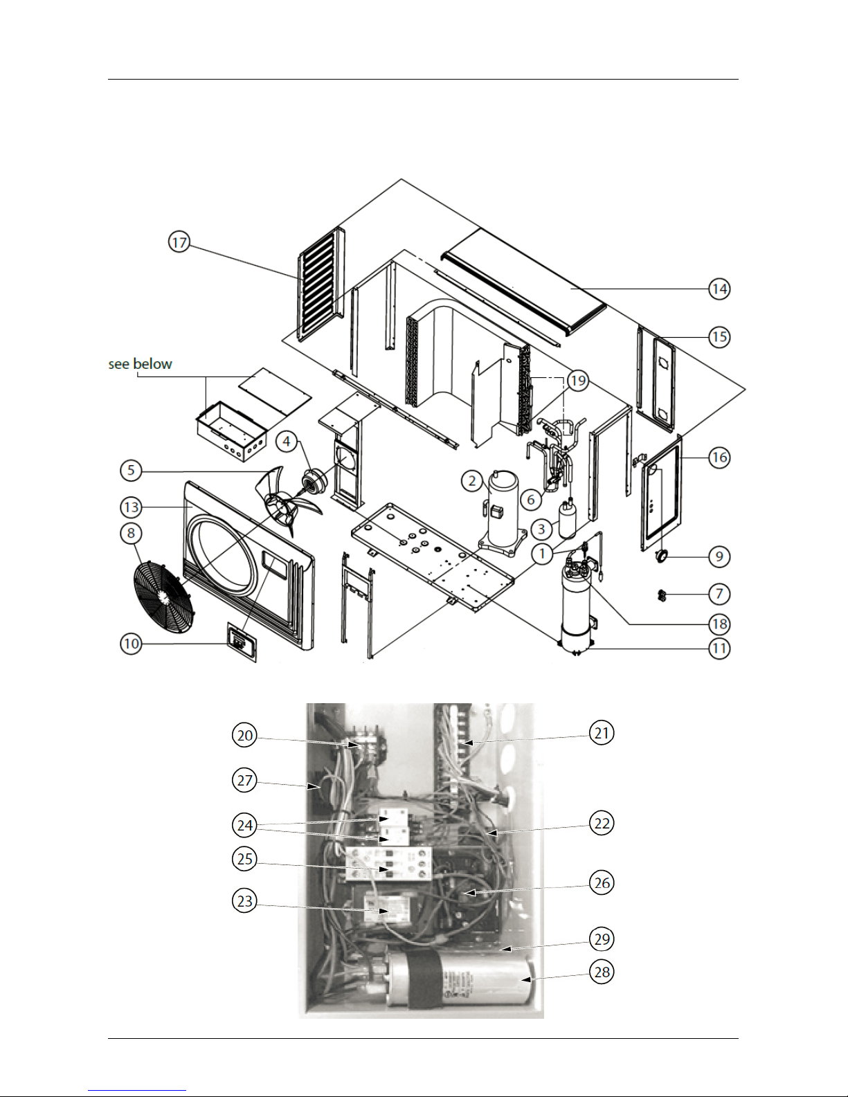
Replacement Parts
1
Illustrated Parts View
28 UltraTemp®-E

No. Part No. Description Spare Part used in
2 474863
Compressor**
√
474865
Compressor**
√
* 474862
Compressor Cable
√ √
4 474873
Fan Motor (incl. Nut & Washer)
√ √
* 474887
Complete R410a Schra
der valve**
√ √ √ √
474889
Fan grill (incl.screws, washers & nuts)
√ √
10 474854
Digital Controller
√ √ √ √
474892
Condensor Kit**
√
474894
Condensor Kit**
√
16 474903
Right Panel
√ √
17 474905
Left Panel
√ √
18 473665
Water Temperature Sensor
√ √ √ √
20 474850
Terminal Blocks (power supply) + wire harness
√ √ √ √
22 474852
Terminal Blocks (24V) + wire harness
√ √ √ √
24 474855
24V Relay (inc
l.socket)
√ √ √ √
474857
Compressor contactor (25A)
√
* 474859
High Pressure switch**
√ √ √ √
26 474872
Soft Starter
√
474876
Fan Motor Capacitor
√ √
474868
Compressor Capacitor
√
29 474870
Soft Started Capacitor
√
* 474908
Winterizing Cover
√ √
E - 08 E - 10 E - 12 E - 15
1 474861 Water Flow Switch √ √ √ √
474864 Compressor** √
474866 Compressor** √
3 474871 Refrigerant Accumulator** √
474874 Fan Motor (incl. Nut & Washer) √ √
5 474877 Fan Blade √ √
474878 Fan Blade √ √
* 474879 Evaporator plastic grill √ √
* 474880 Evaporator plastic grill √ √
6 474881 4-way Valve (Mechanical)** √ √
474882 4-way Valve (Mechanical)** √
474883 4-way Valve (Mechanical)** √
* 474884 4-way Valve (Solenoid) √ √ √ √
7 474885 Cable Glands (PG16) √ √
474886 Cable Glands (PG20) √ √
8 474888 Fan grill (incl.screws, washers & nuts) √ √
9 474890 Gas pressure gauge (incl.support)** √ √ √ √
11 474891 Condensor Kit** √
474893 Condensor Kit** √
* 474895 Accessory bag (water IN/OUT conn. + 4x silentblocs) √ √ √ √
13 474896 Front Panel √ √
474897 Front Panel √ √
14 474898 Top Panel √ √
474899 Top Panel √ √
15 474900 Back Panel √ √
474901 Back Panel √
474902 Back Panel √
474904 Right Panel √ √
474906 Left Panel √ √
19 473665 Defrost Temperature Sensor √ √ √ √
21 474851 Terminal Blocks (input/output conn.) + wire harness √ √ √ √
23 474853 Transformer 230V/24V √ √ √ √
25 474856 Compressor contactor (18A) √ √
474858 Compressor contactor (32A) √
474860 Low Pressure switch** √ √ √ √
27 474875 Fan Motor Capacitor √ √
28 474867 Compressor Capacitor √ √
474869 Compressor Capacitor √
* 474907 Screw Set √ √ √ √
474909 Winterizing Cover √ √
* Not Shown
** replacing this component requires changing the refrigerant
29

30 UltraTemp®-E
 Loading...