

Pentair ULTRATEMP 70, ULTRATEMP 140 H/C, ULTRATEMP 110, ULTRATEMP 140, ULTRATEMP 120 H/C Installation And User Manual
...
FRANÇAIS
ULTRATEMP
HEAT PUMP
®
ENGLISH
ESPAÑOL
IMPORTANT SAFET Y INST RUC TION S
READ AND FOLLOW ALL INSTRUCTIONS
SAVE THESE INSTRUCTIONS
INSTALLATION AND
USER’S GUIDE


i
ULTRATEMP® Heat Pump Installation and User’s Guide
General Features
1
Heat Pump Timer
18
Installation and Location .....................................
2
Relay Remote
18
Materials Needed for Installation
2
RS-485 Remote (Serial Cable)
18
Equipment Pad
2
AutoSet Operation
19
Drainage and Condensation, Roof Run Off,
Extend Operation
19
and Lawn Sprinklers
2
Timers and Delays
20
Heat Pump Dimensions
2
Control Panel Alarm Messages
20
Location and Clearances
3
Service Menu Tree Guide
21
Anchor Clamp Installation
3
Setting Temperature Scale
22
Water Connections and Plumbing
4
Set Water Temperature Offset
22
Automatic Flow Control Valve
4
Defrost Cycle
22
Water Connections to the Heat Pump
5
Run Time Counters
22
Drainage Connection to the Heat Pump
5
Locking the Control Panel
22
CUSTOMER SERVICE / TECHNICAL SUPPORT
If you have questions about ordering Pentair Aquatic Systems, (“Pentair”) replacement parts, and pool products,
please use the following contact information:
Customer Service (8 A.M. to 4:30 P.M. — Eastern
and Pacific Times)
Phone: (800) 831-7133
Fax: (800) 284-4151
Web site
visit www.pentairpool.com or www.staritepool.com to
find information about Pentair products.
TABLE OF CONTENTS
Important Warning and Safety Instructions .......
Menu Tree Quick Start Guide ..............................
Before Installing the Heat Pump .........................
Heat Pump Overview
Installation Requirements
General Installation Information
Water Pressure Switch Adjustment 6
Multiple Unit Installation 7
Heat Pump, Heater, Solar Combination 7
Multiple Heat Pump Connections 7
Electrical Connections and Wiring 9
Wiring Diagram – ( Single P has e – 50/60 Hz) 10
Wiring Diagram – (Three Phase – 60 Hz) 11
Connecting to an Automation System .................. 12
Remote Operation 12
Relay Remote Controls 12
Connecting to IntelliTouch or EasyTouch via
Heat Pump Spade Terminals 13
Connecting to IntelliTouch or EasyTouch via
RS-485 Connector 14
Pin Configuration for Heat Pump Control
B
oard to IntelliTouch 15
Connecting IntelliTouch or EasyTouch to the
Heat Pump 15
For pool energy saving tips, refer to page 16, under “Operating the Heat Pump”. For technical data, voltage
requirements, or ambient/water flow information, refer to page 25 at the back of the manual.
P/N 474099 Rev. Q 6/29/17
ii
iii
1
1
1
1
Technical Support
Sanford, North Carolina (8 A.M. to 4:30 P.M. ET)
Phone: (919) 566-8000
Fax: (919) 566-8920
Moorpark, California (8 A.M. to 4:30 P.M. PT)
Phone: (805) 553-5000 (Ext. 5591)
Fax: (805) 553-5515
Operating the Heat Pump
Swimming Pool Energy Saving Tips
Heat Pump Control Panel Overview
Operator Menu Tree Guide
Starting and Stopping the Heat Pump
Changing the Set Point - Pool and Spa
Heat, Cool, and Auto Modes
....................................... 16
16
16
17
18
Maintenance
Water Chemistry
Winterizing
Spring Start Up
Inspection and Service
Owner Inspection
Professional Maintenance and Service
Technical Information
Electrical Supply - Voltage Requirements
Temperature Resistance Chart
Ambient/Water Flow Table for Professional
Maintenance and Service
Heat Pump Pressure Drop
Troubleshooting
Replacement Parts
Illustrated Parts View
Parts List
............................................................ 23
23
23
23
23
23
............................................ 25
25
26
26
..................................................... 27
................................................. 31
31
32
18
18
24
25

ULTRATEMP® Heat Pump Installation and User’s Guide
IMPORTANT WARNINGAND SAFETY INSTRUCTIONS
ENGLISH
Important Notice:
This guide provides installation and operation instructions for the
UltraTemp
®
Hea
t P
ump. Consul
t Pent
air with any question
this equipment.
Attention Installer: This guide contains important information about the
installation, operationandsafeuseof thisproduct. Thisinformationshould
be given to the owner and/or operator of this equipment after installation
or left on or near the heat pump.
Attention User: This manual contains important information that will
help you in operating and maintaining this heat pump. Please retain it
for future reference.
Before installing this product, read and follow all
warningnoticesandinstructionswhichareincluded.
Failure to follow safety warnings and instructions can result in severe
injury, death, or property damage. Call (800) 831-7133for additional free
copies of these instructions.
Codes and Standards
UltraTempheatpumpsarelistedbyETLascomplyingwiththelatestedition
of the “UL Standard for Safety for Heating and Cooling Equipment”, UL
1995 and CSAC22.2 No. 236.
All Pentair heat pumps must be installed in accordance with the local
building and installation codes as per the utility or authority having
jurisdiction. All local codes take precedence over national codes. In the
absence of local codes, refer to the latest edition of the National Electric
Code (NEC) in the United States and the Canadian Electric Code (CEC)
in Canada for installation.
RISK OF ELECTRICAL SHOCK OR
ELECTROCUTION.
The electrical supply to this product must be installed by a licensed,
certified electrician or qualified personnel in accordance with the
National Electrical Code and all applicable local codes and ordinances.
Improper installation will create an electrical hazard which could result
in death or serious injury to pool or spa users, installers, or others due
to electrical shock, and may also cause damage to property. Read and
follow the specific instructions inside this guide.
Do not permit children to use this product.
F
or units intended for use in other than single-
family dwellings, a clearly labeled emergency
switch shall be provided as part of the installation. The switch shall be
readily accessible to the occupants and shall be installed at least 5 feet
[1.52 m] away, adjacent to, and within sight of the unit.
Consumer Information and Safety
The UltraTemp series of heat pumps are designed and manufactured to
providesafeandreliableservicewheninstalled, operatedandmaintained
according to the information in this manual and the installation codes
referred toinlater sections. Throughout the manual, safety warnings and
cautions are identified by the
with all of the warnings and cautions.
hazardous. See below for water temperature guidelines before setting
temperature.
Safety Commission should be observed when using the spa.
The U.S. Consumer Product Safety Commission
warns that elevated water temperature can be
The following “Safety Rules for Hot Tubs”
recommended by the U.S. Consumer Product
“ symbol. Be sure to read and comply
s r
egarding
1.
Spa or hot tub water temperatures should never exceed 104° F. [40°
C.]. Atemperatureof 100° F. [38° C.] isconsideredsafefor ahealthy
adult. Special caution is suggested for young children. Prolonged
immersion in hot water can induce hyperthermia.
2.
Drinking of alcoholic beverages before or during spa or hot tub
use can cause drowsiness which could lead to unconsciousness
and subsequently result in drowning.
3.
Pregnant women beware! Soaking in water above 100° F.
[38° C.] can cause fetal damage during the first three months of
pregnancy (which may result in the birth of a brain-damaged or
deformed child). Pregnant women should stick to the 100° F. [38°
C.] maximum rule.
4.
Before entering the spa or hot tub, the user should check the
water temperature with an accurate thermometer. Spa or hot tub
thermostats may err in regulating water temperatures.
5.
Personswithamedical historyof heart disease, circulatoryproblems,
diabetes orbloodpressureproblems shouldobtaintheir physician’s
advice before using spas or hot tubs.
6.
Persons taking m edication which induce drowsiness, such as
tranquilizers, antihistamines or anticoagulants should not usespas
or hot tubs.
Hyperthermiaoccurswhentheinternal temperatureof thebodyreachesa
level several degreesabovenormal bodytemperatureof 98.6° F. [37° C.].
The symptoms of hyperthermia include: drowsiness, lethargy, dizziness,
fainting, and an increase in the internal temperature of the body.
The effects of hyperthermia include:
1.
Unawareness of impending danger.
2.
Failure to perceive heat.
3.
Failure to recognize the need to leave the spa.
4.
Physical inability to exit the spa.
5.
Fetal damage in pregnant women.
6.
Unconsciousness resulting in danger of drowning.
Warranty Information
Heat pumps are sold with a limited factory warranty. Details are specified
on the warranty card. Make all warranty claims to an authorized Pentair
dealer or directly tothe factory. Claims must include the heat pump serial
number and model (this information can be found on the rating plate),
installationdate, andnameof theinstaller. Shippingc ostsarenot included
in the warranty coverage. This warranty does not cover damage caused
by improper assembly, installation, operation, improper w ater chemistry
balancing or other chemical abuse, or improper sanitation application,
winterizing, fieldmodification, or failuretoearthbondandproperlyground
theunit.Anychangestotheheat pump, evaporator, heat exchanger, wiring,
or improper installation may void the warranty.
General Specifications
Installation Location Certified for use:
OUTDOOR USE ONLY. Failure to provide the proper clearances
outlined on page 3 will lower the performance of the heat pump
and void the warranty.
Water Pipe/Heater Connection —Plastic 2” PVC (Unions included)
Flow Rate
Maximum120 gpm[456 lpm] - If systemflow rate exceeds 120 gpm, a
bypass valve is required.
Minimum30 gpm[110 lpm]
MaximumWorking Water Pressure 50 psi
For Electrical Supply and Voltage Requirements, refer tothe table
on page 25.
ii
iii
ULTRATEMP® Heat Pump Installation and User’s Guide
SET= ACT=
OVERRIDE IS ON/OFF
RESTART / PUMP START /
**
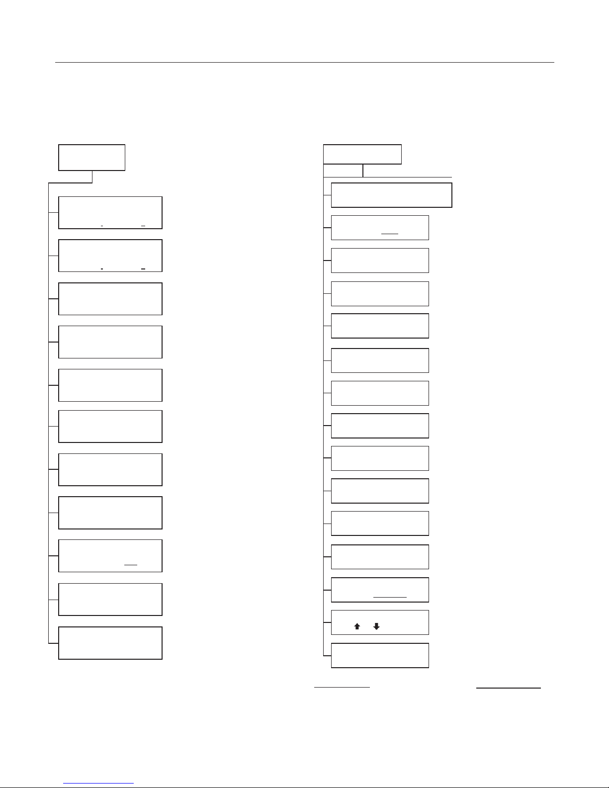
ULTRATEMP® MENU TREE QUICK START GUIDE
1. Push the ON/OFF button to turn the unit on, the green “ON” light should be lit.
2. Select either Pool or Spa mode. The default is Pool mode.
3. Adjust the temperature to the desired setting by pushing either the UP arrow or DOWN arrow.
4. Allow 5 minutes for compressor restart delay.
See pages 17-22 for details on the Operator and Service menu screens on the control panel.
OPERATOR
MENU TREE
SERVICE
MENU TREE
POOL
IDLE/HEAT/COOL
SET= ACT=
SPA
IDLE/HEAT/COOL
HEAT / COOL / AUTO
SET TO - H/C/A
*
HEAT PUMP RUNTIME
REMAINING = NONE
REMOTE MODE
OFF/RELAY/RS-485
LANGUAGE - IDIOMA - LANGUE
ENGLISH / ESPANOL / FRANCAIS
SOFTWARE VERSION
REV.
INTELL ADDRESS
ADDRESS = 1-16
PUMP START TIME
TIME = 1 - 4 HRS
PUMP START DELAY
TIME = 0 - 5 MI N S
TEMPERATURE SCALE
FAHRENHEIT / CELSIUS
WATER TEMP OFFSET
OFFSET = -2 TO +2
AUTOSET
HEAT/COOL/AUTO
EXTEND
HEAT/COOL/AUTO
OVERRIDE IS ON/OFF
SENSING WATER TEMP
DELAYS
SUCTION TEMP
ACTUAL =
ALARM STATUS
HEAT/COOL/AUTO MODE
POOL/SPA
**
**
***
****
DEFROST
ENABLE / DISABLE
AUTOSET
ENABLE / DISABLE
EXTEND
ENABLE / DISABLE
WF HP LP PL SP
1 1 1 0 0
FAN COMP PMP REV
1 1 1 0
TEMP. RECORD
HOUR # °F
RUN TIMES/COUNTS
OR TOVIEW
PRESS POOL/SPA
TO EXIT SETUP
THE NUMBER ONE (1) IS
†
DISPLAYED WHENTHE
ASSOCIATED INPUT/
OUTPUT IS ONAND ZERO
††
(0) IS DISPLA YE D WHEN
INPUT/OUTPUT IS OFF.
* Menu appears only if Heat and Cool mode is enabled
at the factory.
** Menu appears only if AutoSet or Extend is enabled in the
Service menu.
*** Menu appears only if a delay is active.
**** Menu appears only if Defrost is enabled in the Service menu.
INPUTSTATUS
†
WF = WA T E R FLOWSWITCH
HP = HIGH REFRIGERANT PRESSURE SWITCH
LP- LOWREFRIGERANT PRESSURE SWITCH
PL- POOL REMOTE
SP - SPAREMOTE
†† OUTPUTSTATUS
FAN - FAN
COMP - COMPRESSOR
PMP - FILTER PUMP
REV - REVERSINGVALVE

ULTRATEMP® Heat Pump Installation and User’s Guide
ENGLISH
1
BEFORE INSTALLING THE HEAT PUMP
UltraTemp® Heat Pump Overview
Your Pentair heat pump will provide you with years of
heated pool enjoyment. Heat pumps operate by taking
heat from the surroun ding air and tr ansferring it into
the water. The warmer the air and th e more humidit y
in the air, the more latent heat is available for heating
your pool. W ith a properly sized heat pum p for your
pool, the heat pump should raise your pool on average
1° F per hour depending on air temperature, humidity,
and water temperature. The ideal or rated condition for
the heat pump is 80° F a ir temperature, 80% re lat i ve
humidity, and 80° F water temperatur e. As conditions
decrease from 80/80/80, the heat pump performance
will decrease slightly.
Heat Pumps are best uti lized to m ainta in a s et water
temperature; they ar e n ot i nten ded to pr o vide ins t ant
or fast heating. It is not r easonable to expec t a heat
pump to perform like a gas heat er whic h h as a much
higher BTU output and f ast er res ponse. Addition all y,
gas heaters are not dependent on environmental
conditions. Swimming pool heat pumps are very similar
to home heating and air conditioning heat pumps and
therefore should be treated similarly.
Proper operation and use of the heat pump is to set
it at your desired tem perature a nd leave it. Your heat
pump will turn on and off automatically to maintain your
desired temperature much like your home HVAC unit.
To take advant age of the sun’s energy, o perate your
heat pump during the heat of the day.
Your heat pump will still operate when the temperature
drops at night, but the out put will be d ecreased. It is
acceptable to shut th e heat pump off and not use it
for extended periods of time. W hen you have a need
to heat your pool, please plan accordingly since it
may take the heat pum p days to heat your pool back
to your desired temperature, depending on your pool
temperature and environmental conditions.
Heat Pump Installation Requirements
Correct installation is required to assure safe operation.
The requirements f or Pentair heat pum ps includ e the
following:
• Dimensions for critical connections.
• Field assembly (if required).
• Appropriate site location and clearances (pages
2-3).
• Proper electrical wiring (p a ges 9-11).
• Adequate water flow (page ii).
This manual provides the information needed to
meet these requirem ents. Review all app licat ion and
installation proced ures completely b efore continuing
the installation.
General Installation Information
1. Installation and service must be performed by a
qualified installer or service agency, and must conform
to all national, state, and local codes.
2. Heat pumps get electrical power from an external
source and provide a dual electronic thermostat
control system for pool/spa combinations or preheat
convenience.
3. This heat pump is specifically designed for heating
fresh water swimming pools and spas. Do not use it as
a general service heater. Consult your dealer for the
appropriate Pentair products for these applications.
General Features
• Dual digital thermostats offer precise temperature control
to maintain the desired separate water temperatures in
pool/spa combinations without overheating or wasting
energy.
• Long-life corrosion resistant composite plastic cabinet
stands up to severe climates and pool chemicals.
• 100% pure titanium heat exchanger assures corrosionfree performance for extra long life.
• Self-diagnostic control panel monitors and troubleshoots
heat pump operations to ensure safe, dependable
operation.
• Autoset (time clock over-ride) feature monitors water
temperature and turns the water circulation pump on and
off as needed to maintain desired pool temperatures.
• Extend (time clock over-ride) feature monitors water
temperature and turns the water circulation pump on and
off as needed to prolong a heating cycle that has been
interrupted.
• Automatic Defrost feature senses refrigerant temperature
and prevents the heat pump from freezing, allowing the
heat pump to operate at even lower temperatures.
• Compatible with all automated control packages. RS485 communication com patible with IntelliTouch
EasyTouch
• Thermos tatic ex pans io n valve (TXV) controls ref r igeran t
flow for optimum efficiency and BTU output over a wider
operating range.
• Elevated base pan for positive drainage of condensation.
• 2-inch plumbing connections for easy installation.
• Separate isolated electrical compartment prevents
internal corrosion, extends heater life.
• Highest efficiency available, meets or exceeds existing
codes and standards.
• Adjustable timer allows the operator to set the heat
pump to run for a predetermined time. Incremental by 10
minutes to a maximum of 99 hours.
• An extensive list of operational conditions, alarms and
water temperatures are logged on the control board. This
information is available for the user to track performance
and troubleshoot issues.
®
Control Systems.
®
and

2
ULTRATEMP® Heat Pump Installation and User’s Guide
INSTALLATION AND LOCATION
When pool equipment is located below the pool surface, aleak fromany component can cause large scale water loss or flooding.
Pentair Water Pool and Spa, Inc. cannot be responsible for such water loss or flooding which may cause damage to property or
to the product. Avoid placing the heat pump in locations where it can cause damage by water or condensate leakage. If this is not possible, provide a
suitable drain pan to catch and divert any leakage.
Only a qualified service person should install the
®
UltraTemp
Heat Pump. Before instal ling this product,
refer to the Important W arning and Safety Instruc tions
on page ii.
Materials Needed for Installation
The following items are needed and are to be supplied
by the installer for all heat pump installations:
1. Plumbing connections (2-inch).
2. Level surface for proper drainage.
3. Suitable electrical s upply line. See rating plate on
unit for electrical specifications. A junction box is not
needed at the heat pum p; connections are made
inside of the heat pump electrical compartment.
Conduit may be attach ed dir ectl y to the hea t pum p
jacket.
4. Electric cutout s witch that will interr upt al l pow er to
the unit. This switch must be with in line of sight of
the heat pump. Check local codes for requirements.
5. Watertight conduit to run the electrical supply line.
Equipment Pad
For proper drainage of condensation and rain water, place
the heat pump on a flat slightly pitched surface, such as
a concrete or fabricated slab (pad).
If possible, place the pad at the same level or slightly
higher than the filter system equipment pad.
Note: Be sure that the pad is pitched not more than 1/4
in. per foot in any direction as needed for runoff.
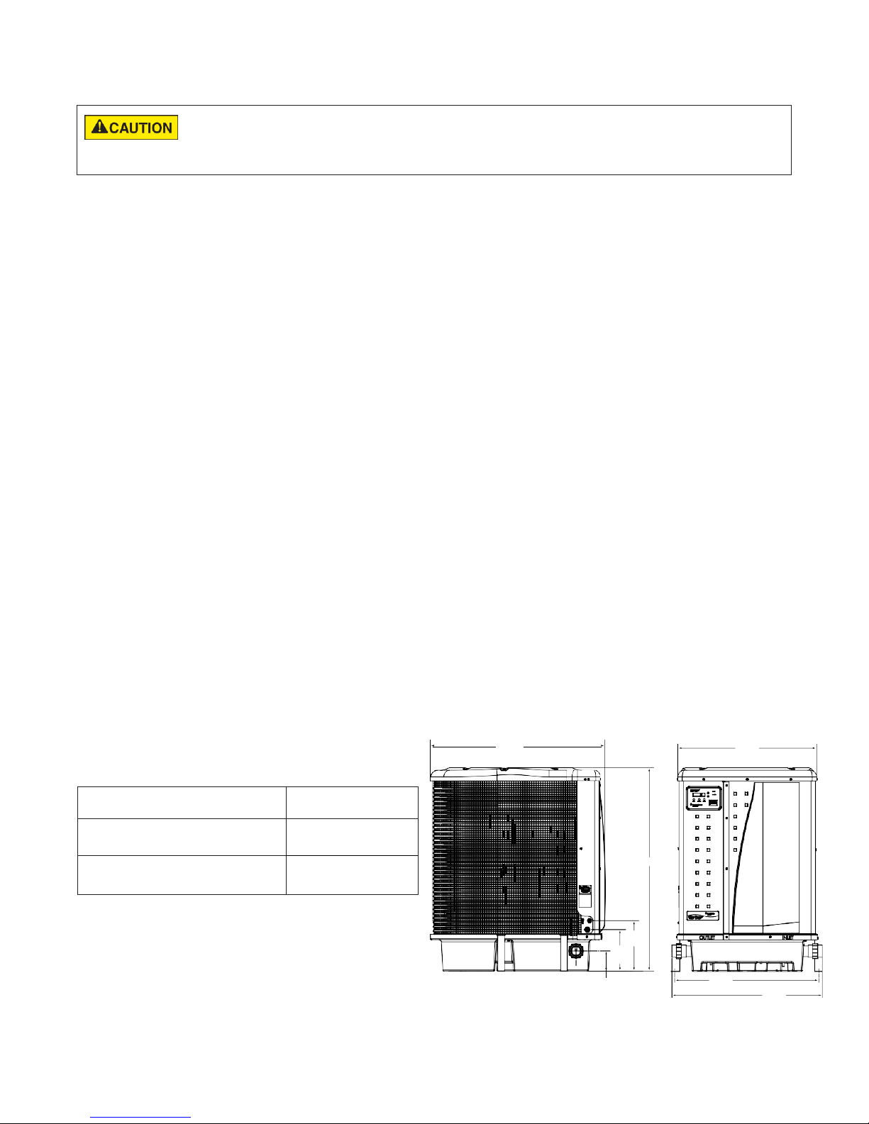
110, 120, 120C, 140C
120 H/C, 140, 140 H/C
Heat Pump Dimensions
MODELS DIMENSION “A”
70, 90 33.5” (851 mm)
45.5” (1156 mm)
Drainage and Condensation
Condensation occurs from the evaporator coil while the
unit is running, and drains at a steady rate (usually three
to five gallons per hour), d epending upon ambient air
temperature and humidity. The more humid the ambient
conditions, the more condensation will be produced.
The bottom of the unit acts as a tray to c atc h rain water
and condensation. Keep th e drain holes, located on the
bottom pan of the base of the unit, clear of debris.
Roof Run-off
Make sure the heat pump is not located where large
amounts of water may run-off from a roof into the unit.
Sharp sloping roofs with out gutters will allow massive
amounts of rain water, m ixed with debris f rom the roof
to be forced throu gh the unit. A gutter or do wn spout
may be needed to protect the heat pump.
Lawn Sprinklers
Avoid placing lawn sprinkler near the heater -
they can spray water into the heater and void the
warranty. Be sure to direct any spraying water away
from the heater. Note the wind direction to be sure
water from sprinklers is not blown toward the heater.
Sprinkler heads can produce high water pressure and
spray at an angle, different from typical rain and humid
weather. Also, sprinklers connected to a well water
system can cause mineral build up on the evaporator
coils and electronics. Salt water can also be an issue if
located near the coast.
38.7"
(983 mm)
(235 mm)
4.5"
(114 mm)
11.25"
(286 mm)
9.25"
A
(813 mm)
32.0"
30.7"
(780 mm)
34.0"
(864 mm)
3
ULTRATEMP® Heat Pump Installation and User’s Guide
ENGLISH
Location and Clearances
All criteria given in the following sections reflect minimum
clearances. However, each installation must also be
evaluated, taking into account the prevailing local
conditions such as pr oximity and height of walls, and
proximity to public access areas.
®
The UltraTemp
clearances on all sides for maintenance and inspection.
1. At least 24 in. [610 mm] access must be available in
the front and 12 in. [305 m m] on all the other sides
of the heat pump for service and proper air flow.
(Manufacturer’s recommendation).
NOSPRINKLERS
12"
(305 mm)
SLAB
Heat Pump m ust be placed to pr ovide
min.
12"
min.
(305 mm)
Heat Pump Location and Clearances
2. If the heat pump is to be installed under a cover
or under a vertical overhang, the unit must have
a minimum of five (5) feet [1.52 m] clearance
from the top of the heat pump. (Manufacturer’s
recommendation).
3. Install a minimum of five (5) feet [1.52 m] from the
inside wall of the pool or spa unless the heat pump
is separated from the pool or spa by a five (5)
foot [1.52 m] high s o li d f en c e or ot her per manent
barrier. Canadian installations require a minimum
of three (3) meters [9.84 ft] from pool water.
4. Install heat pump a minimum of 6 in. [153 mm] from
the wall of the house.
OPEN
AIR FLOW OUT
EVAPORATOR
COILS
SERVICE
ACCESS
24" min.
(610 mm)
3"
(76 mm)
SLAB
OVER HANG
5
FT min.
(1.52 m)
6
"
min.
(153 mm)
AIR
FLOW
IN
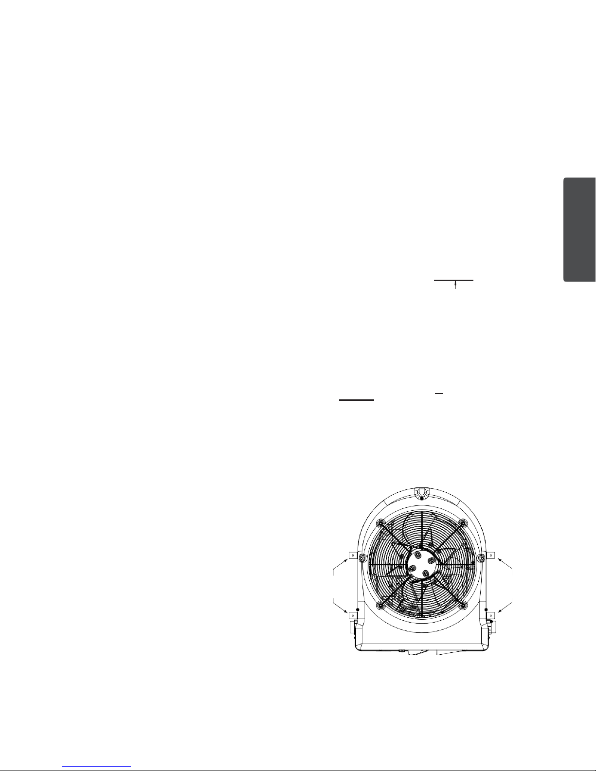
Anchor Clamp Installation
Installation of the anchor clamps is recommended in
all installations. Installation of the anchor clamps is
required in Florida (see Florida Building Code 301.13).
Anchor clamps hold the heat pump to the equipment
pad in order to withstand high winds caused during
extreme weather (i.e. hurricanes).
To install the anchor clamps:
1. Be sure the heat pump is in its permanent location
on the equipment pad.
2. Place the clamps at the base of the heat pump in
the four (4) locations, shown in the image to the
right.
Note: Bolts and bolt anchors are not included with
the heat pump. The installer must provide 1/4” x
1-3/8” stainless steel a nchor bolts and the ap propriate size concrete anchor to mount the clamp to
Heat Pump
Clamps
Anchor Clamp Installation
the equipment pad. Be sure to check local codes.
3. Fit the hook of each clamp over the lip on the
base panel of the heat pump. The hook should fit
between the lip of the base panel and the evaporator coil guard.
Heat Pump
Clamps

4
ULTRATEMP® Heat Pump Installation and User’s Guide
Anchor Clamp Installation, Continued
4. Mark the position of the hole in each clamp on the
equipment pad.
5. Use a masonry drill bit and drill a hole in the cement
with a diameter as determined by the concrete
anchor, at each of the marks on the equipment pad.
The hole should be approximately 1½ in. deep.
6. Insert a bolt a nchor into each of th e ho les. Be sure
the anchors are set completely into the holes.
7. Position the anchor clam ps so that the h oles in th e
clamps are over the bolt anchors.
Be sure that the clamp hooks are over the lip of the
heat pump base.
8. Insert an anchor bolt through each clamp into the anchor
and tighten to secure the clamp and hea t pump to
the equipment pad.
AIR
COIL
HEAT PUMP
BASE
CONCRETE
EQUIPMENT PAD
Anchor Clamp Installation
AIR COIL GUARD
1-3/8" HEX BOLT
(install er provide d)
HEAT PUMP
ANCHOR CLAM P
BOLT ANCHOR
(install er provide d)
CHEMICAL FEEDER
OR CHLORINATOR
TO POOL OR SPA
Water Connections and Plumbing
The image below sho ws the standard p lumbing la yout
with a single UltraTemp
image from right to left for the standard plumbing
sequence.
Arrangement of pool system components (other than the
standard plumbing image below), and the location of the
heat pump (above or below the pool water surface) can
affect the operation of the heat pump’s water pres sure
switch.
The pressure switch c an b e adjust ed to accom m odate
this effect if the heat pum p water connections are no
more than six (6) f eet [1.82 m] below the pool water
surface.
See instructions for pressure switch adjustment on page
6. If the heat pump is installed outside of this range, an
external pressure switch may need to be installed in the
plumbing upstream of the heat pump.
Note: Be advised that when pool equipment is loc at ed
below the pool surf ace a l eak c an result in large-scale
water loss or flooding. Pentair is not responsible for such
water loss or flooding or damage.
Automatic Flow Control Valve
The inlet/outlet header of the heat pump comes equipped
with an internal automatic flow control valve. The
automatic flow contro l valve maintains the proper flow
through the heat pump at rates up to 120 gpm (456 lpm).
If the filter system flow rate is higher than 120 gpm (456
lpm), install a manual bypass valve, see im age below.
Note: Be advised that if your circulation pump is over 2
HP or if the total flow exce eds 120 g pm (456 lpm ), you
will have to add an external bypass valve. Excess water
flow will damage the heat exchanger.
HEAT PUMP
MANUAL BYPASS VALVE
(Optional)
Standard Plumbing Layout
FILTER
®
Heat Pump unit. Follow the
POOL PUMP
FROM POOL OR SPA
5
ULTRATEMP® Heat Pump Installation and User’s Guide
ENGLISH
Water Connections to the Heat Pump
2 in. Quick Connect f ittings have been inst alled on the
water inlet and outlet c onnections. Filtered cool water
is plumbed to the in let, located on the right side of th e
UltraTemp
outlet, located on the left side of the heat pump.
Plastic piping (PVC Schedule 40) should be connected
to the heat pump. The unions, provid ed with the unit,
accept 2 in. PVC pipe.
®
Heat Pump. Heated water flows through the
WATER
INLET UNION
WATER
OUTLET UNION
Drainage Connection to the Heat Pump
A 5/8” x 1/2” NPT thread ed dr ain hose bar b is includ ed
with the heat pump union kit.
Before operating the heat pump for the first time, the drain
hose barb must be installed into th e thr ea ded dra in age
outlet located in the base of the heat pump.
To install the Drain Hose Barb and Drain Hose:
1. Thread the drain hose barb into the threaded drainage
outlet in the base of the he at pump. See the image
below.
2. Connect a 5/8” garden hose to the hose barb.
3. Ensure the end of the gard en hose is pos itioned s o
that drainage will flow away from the heat pump and
equipment pad.
DRAIN HOSE BARB
5/8" X 1/2" NPT
Heat Pump Water Connections
Always be sure that flow requirements and pool
water turnover rates can be maintained with the
DRAINAGE
OUTLET
Drain Hose Barb Installation
installation of additional heat pumps and plumbing restrictions.

6
ULTRATEMP® Heat Pump Installation and User’s Guide
the
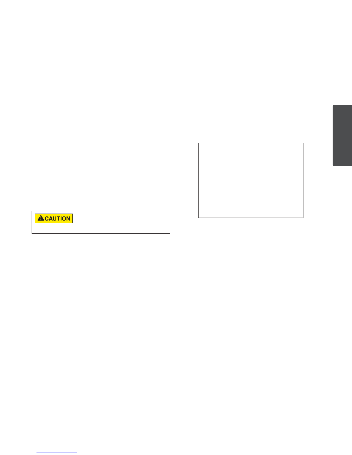
Water Pressure Switch Adjustment
The water pressure switch should be adjusted to
turntheheater off whenthepumpis off. Settingthe
switchto closeat too lowof aflowcan damage the appliance. Adjust
switch toturnthe heater off, not on.
The pressure switch is preset at the factory for
activation at 1.5 psi [10 kPa]. This factory setting
works for most basic installations. Only adjust the
water pressure switch if the heat pump does not
operate when the proper flow is applied to unit
or if the heat pump does not shut off when the
filter pump is off. Occasionally, unusual plumbing
configurations or necessary restrictions in the
plumbing may cause pressure sensing problems.
In these rare situations, the plumbing system
configuration may require adjustment of the water
pressure switch.
Adjustment of the pressure switch may be necessary
if any part of the filter system piping is 3 feet [0.91 m]
or more above the top of the heat pump.
In general, if the heat pump is installed more than 6
feet [1.83 m] below the pool surface, an external water
flow switch must be added to the plumbing system.
On some installations, the piping from the heat pump
to the pool is very short. The back pressure could be
too low to trigger the pressure switch. If this happens,
install a directional fitting or elbow where the return
line enters the pool. This will increase back pressure for
the heat pump to operate properly. Be sure to check that
the system flow is above the minimum requirement of 30
gpm (110 lpm) after the directional fitting installation.
Be sure the pool filter is clean before making any
pressure switch adjustment: A dirty filter will restrict
the water flow and the pressure switch cannot be
adjusted properly.
To adjust the pressure switch:
The following adjustment is for installations where
the heat pump is below pool water level.
1. Be sure that all valves in the system are set to allow
water flow through the heat pump. Start t he filter
pump.
2. Set the heat pump temperature above the actual
temperature to call for heat.Turn the heat Pump ON.
3. Once the heat pump is running, turn off the filter
pump. The heat pump should turn off immediately.
4. If the heat pump continues to operate when the filter
pump is off, then the water pressure switch needs to
be adjusted.
5. Remove the heat pump’s left front panel and remove
remaining right front panel.The water pressure switch
is located in the water plum bing in the lower right
corner of the heat pump.
6. Slowly rotate the adjustment wheel on the water
pressure switch in a clockwise direction until the “LOW
WATER FLOW ” Alarm shows on the LCD, the red
SERVICE light turns ON, and the heat pump stops.
7. Check the setting of the water press ure switch by
starting and stopp ing the filter pum p and check ing
the control panel and operation of the heater between
each flow change.
8. If the water pressure switc h cannot be adjus ted to
accommodate the conditions listed above, an external
flow switch mus t be adde d t o the plum bing s ystem
to ensure that the heat pump will not operate without
the proper flow through the heat exchanger.
The following adjustment is for installations where
the heat pump is above pool water level.
1. Be sure that all valves in the system are set to
allow water flow through the heat pump. Start the
filter pump.
2. Set the heat pump temperature above the actual
temperature to call for heat. Turn the heat pump
ON.
3. If the LCD shows a “LOW WATER FLOW” Alarm
and red SERVICE light is present then the water
pressure switch needs to be adjusted.
emove the UltraTemp® Heat Pump’s left front
4. R
panel and remove remaining right front panel.
The water pressure switch is located in the water
plumbing in the lower right corner of the heat
pump.
5. Slowly rotate the adjustment wheel on the water
pressure switch in a counterclockwise direction
until the “LOW WATER FLOW” Alarm and red
SERVICE light vanish, time delay countdown will
start.
6. Once the heat pump is running, turn off the filter
pump. The heat pump should turn off immediately.
7. If the heat pump continues to operate when the
filter pump is off, turn the adjustment wheel on
the water pressure switch in a clockwise direction
until the “LOW WATER FLOW” Alarm shows on
the LCD, the red SERVICE light turns ON, and the
heat pump stops.
8. Check the setting of the water pressure switch by
starting and stopping the filter pump and checking
the control panel and operation of the heater
between each flow change.
9. If the water pressure switch cannot be adjusted
to accommodate the conditions listed above,
an external flow switch must be added to the
plumbing system to ensure that the heat pump will
not operate without the proper flow through the
heat exchanger.
 Loading...