

Page 1
U3 - U5 - U6
U3 K U3 K SPEZIAL U5 K U6 KE U6 KD
U3 KS U3 KS SPEZIAL U5 KS U6 KES U6 KDS
EN Instruction Manual
JUNG-PUMPEN.DE B 42054-30-1806
Page 2
2
ENGLISH
You have purchased a product made by
JUNG PUMPEN and with it, therefore, also
excellent quality and service. Secure this
service by carrying out the installation
works in accordance with the instructions, so that our product can perform
its task to your complete satisfaction.
Please remember that damage caused
by incorrect installation or handling will
adversely affect the guarantee. Therefore please adhere to the instructions in
this manual!
This appliance can be used by children
aged 8 years or over and by persons with
limited physical, sensory or intellectual
capabilities, or with limited experience
and knowledge, provided that they are
supervised or have been instructed in
the safe use of the appliance and are
aware of the dangers involved. Children
must not be allowed to play with the appliance. Cleaning and user maintenance
must not be carried out by children unless they are supervised.
Damage prevention in case of failure
Like any other electrical device, this product
may fail due to a lack of mains voltage or a technical defect.
If damage (including consequential damage) can
occur as a result of product failure, the following
precautions can be taken at your discretion:
• Installation of a water level dependent (under
circumstances, mains-independent) alarm
system, so that the alarm can be heard before
damage occurs.
• Inspection of the collecting tank/chamber for
tightness up to the top edge before – or at the
latest, during – installation or operation of the
product.
• Installation of backow protection for drain-
age units that can be damaged by wastewater
leakage upon product failure.
• Installation of a further product that can com-
pensate in case of failure of the other product
(e.g. duplex unit).
• Installation of an emergency power genera-
tor.
As these precautions serve to prevent or minimise consequential damage upon product failure, they are to be strictly observed as the manufacturer’s guideline – in line with the standard
DIN EN specications as state of the art – when
using the product (Higher Regional Court Frankfurt/Main, Ref.: 2 U 205/11, 06/15/2012).
SAFETY INSTRUCTIONS
This instruction manual contains essential information that must be observed during installation, operation and servicing. It is therefore
important that the installer and the responsible
technician/operator read this instruction manual before the equipment is installed and put into
operation. The manual must always be available
at the location where the pump or the plant is
installed.
Failure to observe the safety instructions can
lead to the loss of all indemnity.
In this instruction manual, safety information is
distinctly labelled with particular symbols. Disregarding this information can be dangerous.
General danger to people
Warning of electrical voltage
NOTICE!
Danger to equipment and operation
Qualication and training of personnel
All personnel involved with the operation, servicing, inspection and installation of the equip-
ment must be suitably qualied for this work
and must have studied the instruction manual
in depth to ensure that they are suciently
conversant with its contents. The supervision,
competence and areas of responsibility of the
personnel must be precisely regulated by the
Page 3
3
ENGLISH
operator. If the personnel do not have the necessary skills, they must be instructed and trained accordingly.
Safety-conscious working
The safety instructions in this instruction manual, the existing national regulations regarding
accident prevention, and any internal working,
operating and safety regulations must be adhered to.
Safety instructions for the operator/user
All legal regulations, local directives and safety
regulations must be adhered to.
The possibility of danger due to electrical energy must be prevented.
Leakages of dangerous (e.g. explosive, toxic,
hot) substances must be discharged such that
no danger to people or the environment occurs.
Legal regulations must be observed.
Safety instructions for installation, inspection
and maintenance works
As a basic principle, works may only be carried out to the equipment when it is shut down.
Pumps or plant that convey harmful substances
must be decontaminated.
All safety and protection components must be
re-tted and/or made operational immediately
after the works have been completed. Their effectiveness must be checked before restarting,
taking into account the current regulations and
stipulations.
Unauthorised modications, manufacture of
spare parts
The equipment may only be modied or altered
in agreement with the manufacturer. The use of
original spare parts and accessories approved
by the manufacturer is important for safety reasons. The use of other parts can result in liability
for consequential damage being rescinded.
Unauthorised operating methods
The operational safety of the supplied equipment is only guaranteed if the equipment is
used for its intended purpose. The limiting values given in the "Technical Data" section may not
be exceeded under any circumstances.
Instructions regarding accident prevention
Before commencing servicing or maintenance
works, cordon off the working area and check
that the lifting gear is in perfect condition.
Never work alone. Always wear a hard hat, safety
glasses and safety shoes and, if necessary, a
suitable safety belt.
Before carrying out welding works or using electrical devices, check to ensure there is no danger of explosion.
People working in wastewater systems must be
vaccinated against the pathogens that may be
found there. For the sake of your health, be sure
to pay meticulous attention to cleanliness wherever you are working.
Make sure that there are no toxic gases in the
working area.
Observe the health and safety at work regula-
tions and make sure that a rst-aid kit is to hand.
In some cases, the pump and the pumping medium may be hot and could cause burns.
For installations in areas subject to explosion
hazards, special regulations apply!
APPLICATION
WARNING!
The pump must only be connected to sockets
that have been installed properly in accordance with the regulations and are protected with
at least 10 A (slow) and RCD-safety switches
(30mA).
DANGER!
The pump must never be used when a person is
in the water.
Submersible pumps from the U3, U5 and U6 series are suitable for pumping domestic waste
water without stones. This includes also water
from household dishwashers and household
washing machines.
The U3 K spezial can also pump aqueous solutions with up to 10% salt content and condensate from gas condensing boilers.
Page 4
4
ENGLISH
The U6 can also pump ground water, drainage
silage liquor and liquid manure.
NOTICE! In outdoor applications, only pumps
with at least a 10-metre mains cable must be
used.
When using the pumps, the relevant national
laws, regulations and stipulations must be adhered to, for example:
• Domestic contaminated and waste water
(e.g. EN 12056 in Europe)
• Installation of low voltage systems
(e.g., VDE 0100 in Germany)
For non-standard utilization conditions, further
regulations must be observed (e.g. VDE 0100
in Germany, part 701: bathrooms and shower
rooms; part 702: swimming pools and fountains
and part 737: outdoor use).
Temperatures
The pumped medium must have a temperature
of max 35°C.
The submersible pump is frost-resistant down
to -20°C when stored in dry conditions. When
installed, however, it must not be allowed to
freeze in the water.
Transport
The pump must always be lifted by the handle
and never by the power supply cable! The pump
should only be lowered into deeper chambers or
pits using a rope or chain.
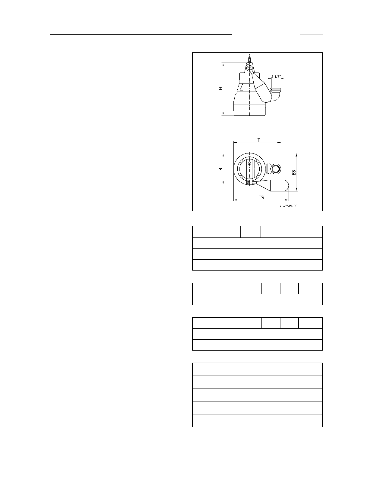
Dimensions [mm]
H B T BS TS
U3 K 255 160 225 195 280
U5 K 280 170 250 205 290
U6 K 335 175 255 210 295
Pumps with special oat assembly, (JP44795)
H BS TS
U3 KS 225 270 220
Pumps with special oat assembly, (JP44207)
H BS TS
U5 KS 280 245 285
U6 KS 335 250 290
Switching points On - Off for built-in switching
Normal Special
● ○ ● ○
U3 KS 215 110 105 45
U5 KS 240 135 - -
U6 KS 270 170 - -
Page 5
5
ENGLISH
ELECTRICAL
CONNECTION
NOTICE! Only qualied electricians may carry
out electrical works to the pump or the controls.
WARNING!
Before carrying out any works: disconnect the
pump and the controls from the mains and take
steps to ensure that no one else can reconnect
them to the power supply.
The relevant standards (such as EN standards),
country-specic regulations (such as VDE in
Germany), and the regulations of the local power
supply companies must be observed.
NOTICE! Never put the mains plug or a free lead
end in water! If water gets into the plug, this can
cause malfunctions and damage.
Observe the operating voltage (see the type
plate)!
The pump is provided with a winding thermostat. In case of unacceptably high temperatures
it switches off the pump to protect it against
possible damage. Unacceptably high temperatures may result e.g. from dry running or mechanical or electrical overload.
CAUTION!
The pump is switched on again automatically after cooling down - risk of injury!
For this reason, always disconnect the device
from the mains before remedying the fault! In
order to do this, unplug from the mains supply
or remove the pre-fuses of the pump controls!
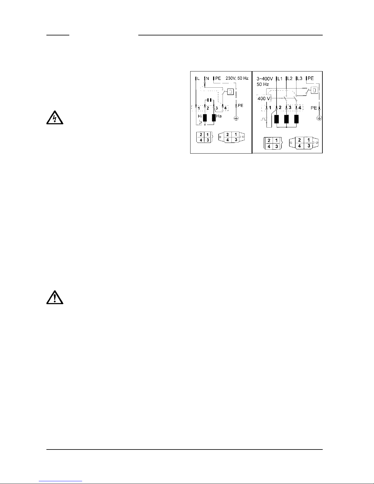
Rotational direction
Applies only for three-phase pumps. The rotational direction must be checked before installation! If the rotational direction is correct, the
start-up jolt should be counter-clockwise. If the
rotational direction is wrong, 2 phases of the
supply cable must be swapped over, because a
wrong direction of rotation results in an overload of the pump.
Alternating and three-phase current circuit diagrams
INSTALLATION
The pump must be installed as shown in the examples. For installations in accordance with EN
12056-4, the pressure pipe must be laid in a loop
above the local backow level and protected
with a backow prevention valve. The rubber
ap supplied (U3 and U5) is for mobile operation
only.
A correspondingly larger diameter pipe should
be used for longer pressure pipelines to avoid
pipe friction losses.
In contrast to pumps with built-in level control,
the ON an OFF switching heights of pumps without built-in level control are variable by the use
of a separate level controller. Our ready to connect level controls can be installed without spe-
cic electrotechnical skills.
Permanent venting may be necessary if the
pump runs dry from time to time (pressure outlet surfaced). This can occur for example if the
residual water in the collecting chamber evaporates or if the pump runs in “snore” mode during
the test run.
To vent the pump housing the attached elbow
must be drilled at the marked location to provide
a 6 mm drill-hole.
NOTICE! If the pump is malfunctioning, part of
the contents of the oil reservoir could escape
into the pumping medium.
Page 6

6
ENGLISH
Dimensions of chamber
Single installation with pump base: 40 x 40 cm
Single installation with guide rail system:
40 x 50 cm and Duplex installation: 50 x 50 cm
Example of installation with guide rail system
Installation
Fix the coupling base rmly to the oor of the
collection chamber using wall plugs and then
mount the guide rail. Next, install the pressure
pipe including the necessary ttings, such as
the non-return valve and shut-off valves.
Reseal the coupling catch at the pump and
tighten it until it is “hand tight”. Finally, t the
pump with the coupling catch onto the guide rail
and lower it into place using a chain xed to the
handle.
Example of installation Duplex unit
NOTICE! The oats of the level controller and
alarm system are installed so that they are freely
movable but not under the inlet. Please observe
the minimum distances. The controls may only
be installed in a dry and well ventilated room!
Flushing device
The pump can keep the intake section at the
bottom of the chamber clear of deposits to a
large extent if you carry out a small modication. This reduces the performance of the pump
only insignicantly.
This modication is carried out as follows. De-
tach the foot strainer and carefully drill a hole
into the 3 markings with the ø 5 symbols. Deburr the drillholes. When reattaching the foot
strainer, ensure that the new drill-holes are not
covered by the bars of the foot strainer. The U5
and U6 ranges provide markings on the housing
and the foot strainer to help you.
Low level pumping
Flooded areas can be pumped out leaving only
few mm of residual water without the need for
optional extras, U3K: 5 mm, U5K: 6 mm and U6K:
10 mm. To do so, the foot strainer must be levered off with a screwdriver. In the case of pumps
with an attached control, the oat switch must
be locked in the ON position. It is not possible
therefore in low level pumping to operate the
pump in switching mode.
To make the pump operate, the drainage hose
must be emptied before each pumping run and
there must be a minimum water level available of,
for U3K: 40 mm, for U5K: 60 mm and for U6K: 90
mm.
Page 7

7
ENGLISH
Mobile operation
For safety reasons, mobile operation is only al-
lowed with a foot strainer.
If a hose is used as a pressure line, care must
be taken to ensure that for every pumping operation the hose is completely empty before the
pump is submersed. Any residual liquid would
obstruct the ventilation of the pump housing
and therefore also hinder the pumping operation. For the same reason, the pump would not
operate if it was switched on before being submersed.
The pump can also be vented by providing a 6
mm drill-hole in the pump housing. This drillhole allows the pump to be vented even if the
rubber ap is used.
The enclosed rubber ap (not Flutboxand U6)
is tted in the pressure outlet (U3) or in the attached elbow (U5). Ensure that the ap opens in
the direction of ow.
Enlarging the free passage
The free passage of the U5 and U6 pump ranges
can be enlarged from 10 to 20 mm. This is done
by levering off the foot strainer and attaching
the enclosed extensions to the integrally mold-
ed pump feet. The foot strainer no longer ts
under the pump.
MAINTENANCE
We recommend that you service the equipment
in accordance with EN 12056-4.
WARNING!
Before carrying out any works: disconnect the
pump and the controls from the mains and take
steps to ensure that no one else can reconnect
them to the power supply.
WARNING!
Check the mains cable for signs of mechanical
and chemical damage. Damaged or kinked cables must be replaced.
NOTICE! If the water contains high levels of iron
or lime, insucient cleaning can result in irreparable damage to the seal and thus also to the
pump motor in the long term.
Consequently, the pump must be cleaned at
regular intervals according to the hardness of
the water.
Cleaning
The foot strainer prevents coarse impurities
from entering the pump. Regular cleaning of the
oat and the foot strainer ensures optimum performance and operation.
Page 8
8
ENGLISH
Cleaning of the impeller (U5 and U6)
To clean the impeller, and in the event of an
obstacle or blockage, the foot strainer must be
levered off. After this, take out the screws on the
underside of the pump and remove the cover.
The impeller can now be cleaned.
CAUTION!
Worn impellers can have sharp edges.
If the pump performance decreases, the impel-
ler must be checked for wear and replaced by
the manufacturer if necessary.
Tightening torque M
A
for A2 screw materials
for M 5 M
A
= 5 Nm
for Amtec 3,5 M
A
= 1 Nm
for Amtec 5,0 MA = 2 Nm
QUICK TIPS FOR
REMEDYING FAULTS
Pump does not work
• Check mains current (do not use a pin gauge)
• Fuse faulty = may be too weak (please refer to
Electrical Connection)
• Mains supply cable damaged = repair to be
carried out by manufacturer only
Pump runs but does not pump
• Empty the pressure pipe or hose to allow the
non-return valve to open and the air to escape
from the pump housing, it may be necessary
to carry out a ventilation drilling
Impeller blocked
• Solids and brous matter have become lod-
ged in the pump housing = clean
Decreased pumping performance
• Foot strainer obstructed = clean
• Pressure pipe obstructed = clean
• Rotor worn out = repair to be carried out by
the manufacturer
• Wrong direction of rotation (for a three-pha-
se current) = ask a qualied electrician to
change 2 phases of the supply line
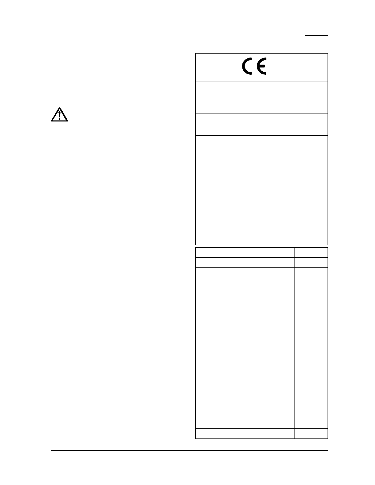
0197
JUNG PUMPEN GmbH - Industriestr. 4-6
33803 Steinhagen, Germany
13
401.13.1612
EN 12050-2:2001
Lifting plant for faecal-free wastewater DN 32
U3 K (JP00205/2)
U3 K spez. (JP09562/2)
U3 KS (JP00206/2)
U3 K spez. (JP44255)
U3 KS (JP09808/2)
U3 KS spez. (JP09563/2)
U3 KS spez. (JP45195)
U5 K (JP09386/0)
U5 KS (JP09387/0)
U5 KS (JP09417/0)
U6 K E (JP00226/2)
U6 K D (JP00228/3)
U6 K ES (JP00227/2)
U6 K ES (JP09260/2)
U6 K DS (JP00229/3)
U6 K DS (JP09261/3)
Collecting and automatically lifting faecal-free
waste water above the backow level in buildings
and sites
REACTION TO FIRE NPD
WATERTIGHTNESS Pass
EFFECTIVENESS (LIFTING EFFECT
- Pumping of solids Pass
- Pipe connections Pass
- Ventilation NPD
- Minimum ow velocity Pass
-
Minimum free passage of the plant
Pass
- Minimum useful volume NPD
MECHANICAL RESISTANCE
- Load bearing capacity and structural
stability of collection tank for use
NPD
- Structural stability of collection tank
for use inside buildings
NPD
NOISE LEVEL ≤ 70 dB(A)
DURABILITY
- of structural stability NPD
- of lifting effectiveness Pass
- of mechanical resistance NPD
DANGEROUS SUBSTANCES
NPD
Page 9

9
DE - Technische Daten EN - Technical Data FR - Caractéristiques Techniques
NL - Technische Gegevens IT - Dati Tecnici PL - Dane Techniczne
CZ - Technické Údaje HU - Műszaki Adatok RO - Date Tehnice
U3 K/KS U5 K/KS U6 KE/KES U6 KD/KDS U3 KS U6 KES
[kg] 3,7 / 3,4 4,7 / 4,5 5,9 / 5,3 6,6 / 5,8 3,4 5,3
DN 32 32 32 32 32 32
[mm] 10 10 / 20 10 / 20 10 / 20 10 10 / 20
P1 [W] 320 520 750 750 320 750
P2 [W] 200 380 490 550 200 490
U [V] 1/N/PE ~230 1/N/PE ~230 1/N/PE ~230 3/PE ~400 1/N/PEx230
1/N/PEx230
f [Hz] 50 50 50 50 60 60
I [A] 1,4 2,3 3,3 1,3 1,4 3,3
DE - Leistungen EN - Performance FR - Puissances
NL - Capaciteit IT - Prestazione PL - Wydajności i moce
CZ - Výkony HU - Teljesítmény RO - Capacităţi
H [m]
1 2 3 4 5 6 7 8 9
Q [m3/h]
U3
6,5 5,5 5,0 4,0 3,0 1,5
U5 11,5 10,5 9,0 7,5 6,5 4,5 2,5
U6 15,5 14,5 13,0 11,5
9,5 8,0 6,0 4,0 1,5
Page 10
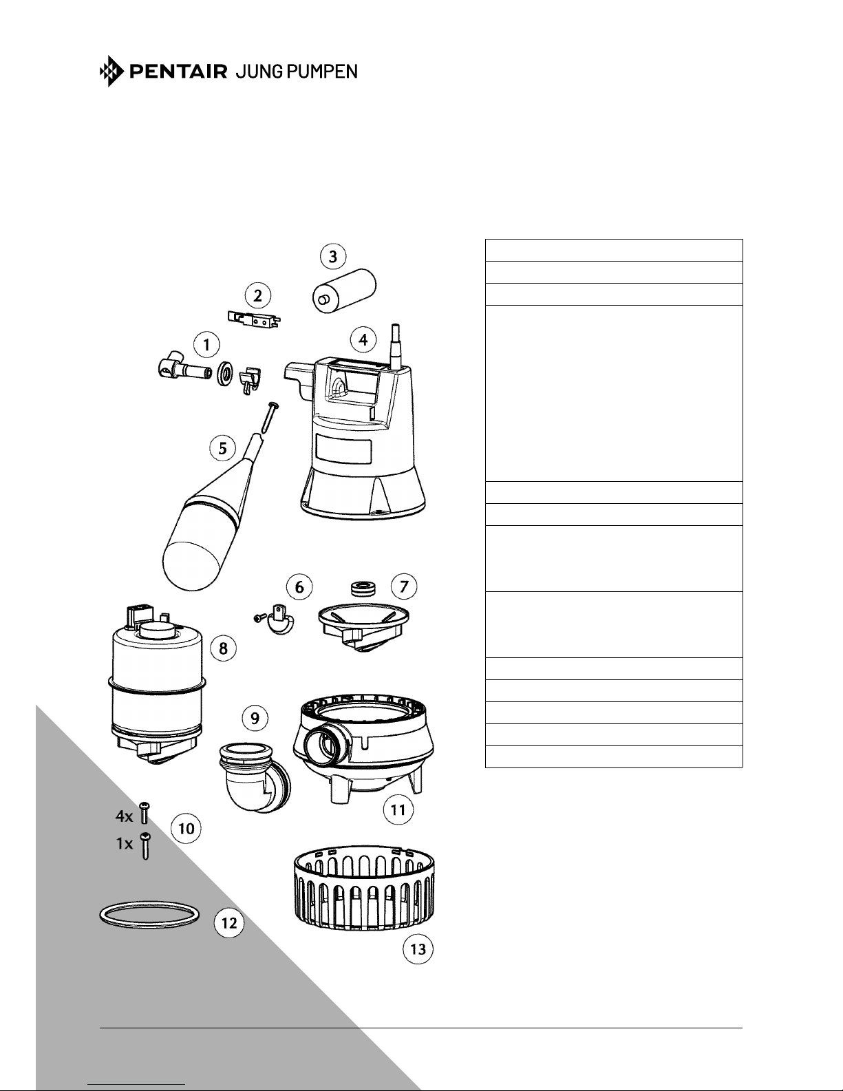
Ersatzteile - Spare parts - Pièces de rechange - Reserveondrdelen - Parti di ricambio - Reservedele - Reserv delar
Varaosat - Części zamienne - Náhradní díly - Alkatrészek - Piese de schimb - Запасные части -
备件
U3K /2 · U3KS /2 · U3K SPEZIAL /2 · U3KS SPEZIAL /2
JUNG-PUMPEN.DE B 40885-21-1809
①
Schaltwelle Shift shaft
JP42770
②
Mikroschalter Microswitch
JP46351
③
Kondensator Capacitor
JP46353
④
Anschlusseinheit Top cover
U3 K, 10m
JP46379
U3 KS, 4m
JP46380
U3 KS, 10m
JP46384
U3 K spez., 5m
JP46522
U3 K spez., 10m
JP46381
U3 KS spez., 4m
JP46382
U3 KS spez., 10m
JP46383
⑤
Schwimmer Float
JP42771
⑥
Gummiklappe Rubber ap
JP46356
⑦
Laufrad Impeller
U 3 K
JP46358
U 3 K spezial
JP46378
⑧
Motor Motor
U 3 K
JP46361
U 3 K spezial
JP46362
⑨
Winkel Elbow
JP46355
⑩
Schraubensatz Screw set
JP42773
⑪
Spiralgehäuse Volute casing
JP46359
⑫
Dichtungssatz Seal set
JP46354
⑬
Siebfuß Strainer base
JP46360
Page 11

Ersatzteile - Spare parts - Pièces de rechange - Reserveonderdelen - Parti di ricambio - Reservedele - Reserv delar
Varaosat - Części zamienne - Náhradní díly - Alkatrészek - Piese de schimb - Запасные части -
备件
U5K · U5KS
JUNG-PUMPEN.DE B 40887-21-1809
①
Schaltwelle Shift shaft
JP42770
②
Mikroschalter Microswitch
JP46351
③
Kondensator Capacitor
JP46015
④
Anschlusseinheit Top cover
U5 K, 10m
JP46389
U5 KS, 4m
JP46390
U5 KS, 10m
JP46391
⑤
Schwimmer Float
JP42771
⑥
Motor Motor
JP46388
⑦
Dichtungen Seals
JP46385
⑧
Laufrad Impeller
JP46363
⑨
Winkel Elbow
JP46355
⑩
Gummiklappe Rubber ap
JP46366
⑪
Spiralgehäuse Volute casing
JP46364
⑫
Dichtungssatz Seal set
JP46354
⑬
Deckel Cover
JP46387
⑭
Schraubensatz Screw set
JP42773
⑮
Siebfuß Strainer base
JP46365
Page 12
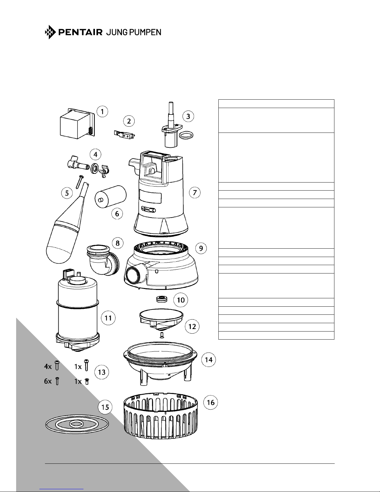
Ersatzteile - Spare parts - Pièces de rechange - Reserveonderdelen - Parti di ricambio - Reservedele - Reserv delar
Varaosat - Części zamienne - Náhradní díly - Alkatrészek - Piese de schimb - Запасные части -
备件
U6 KE /2 · U6 KES /2 · U6 KD /3 · U6 KDS /3
JUNG-PUMPEN.DE B 42055-21-1809
①
Schaltschütz Motor contactor
JP46371
②
Mikroschalter Microswitch
ES
JP46351
DS
JP46352
③
Leitung Cable
E / ES, 4 m
JP42776
E / ES, 10 m
JP42777
D / DS, 4 m
JP42778
D / DS, 10 m
JP42779
10 m, A/NZ-plug
JP47221
④
Schaltwelle Shift shaft
JP42770
⑤
Schwimmer Float
JP42771
⑥
Kondensator Capacitor
JP46374
⑦
Haube Top cover
E
JP46919
D
JP46920
ES
JP46372
DS
JP46373
⑧
Winkel Elbow
JP46355
⑨
Spiralgehäuse Volute casing
JP46368
⑩
Dichtungen Seals
JP46370
⑪
Motor Motor
E / ES
JP46375
D / DS
JP46376
⑫
Laufrad Impeller
JP46369
⑬
Schraubensatz Screw set
JP42773
⑭
Deckel Cover
JP42772
⑮
Dichtungssatz Seal set
JP46354
⑯
Siebfuß Strainer base
JP46367
Page 13
13
EU-Konformitätserklärung
EU-Prohlášeni o shodě
EU-Overensstemmelseserklæring
EU-Declaration of Conformity
EU-Vaatimustenmukaisuusvakuutus
EU-Déclaration de Conformité
EU-Megfelelöségi nyilatkozat
EU-Dichiarazione di conformità
EU-Conformiteitsverklaring
EU-Deklaracja zgodności
EU-Declaraţie de conformitate
EU-Vyhlásenie o zhode
EU-Försäkran om överensstämmelse
e
JUNG PUMPEN GmbH - Industriestr. 4-6 - 33803 Steinhagen - Germany -
www.jung-pumpen.de
DE · Wir erklären in alleiniger Verantwortung, dass das Produkt den aufgeführten Richtlinien entspricht.
CS · Prohlašujeme na svou výlučnou odpovědnost, že výrobek odpovídá jmenovaným směrnicím.
DA · Vi erklærer under ansvar at produktet i overensstemmelse med de retningslinjer
EN · We hereby declare, under our sole responsibility, that the product is in accordance with the specified Directives.
FI · Me vakuutamme omalla vastuullamme, että tuote täyttää ohjeita.
FR · Nous déclarons sous notre propre responsabilité que le produit répond aux directives.
HU · Kizárólagos felelősségünk tudatában kijelentjük, hogy ez a termék megfelel az Európai Unió fentnevezett irányelveinek.
IT · Noi dichiariamo sotto la nostra esclusiva responsabilità che il prodotto è conforme alle direttive citate
NL · Wij verklaren geheel onder eigen verantwoordelijkheid dat het product voldoet aan de gestelde richtlijnen.
PL · Z pełną odpowiedzialnością oświadczamy, że produkt odpowiada postanowieniom wymienionych dyrektyw.
RO · Declarăm pe proprie răspundere că produsul corespunde normelor prevăzute de directivele mai sus menţionate.
SV · Vi försäkrar att produkten på vårt ansvar är utförd enligt gällande riktlinjer.
SK · Na výlučnú zodpovednosť vyhlasujeme, že výrobok spíňa požiadavky uvedených smerníc.
CE 301-13-1611
Steinhagen, 10-11-2016
______________________ i.V. ____________________
Stefan Sirges, General Manager Rüdiger Rokohl, Sales Manager
DE · Weitere normative Dokumente CS · Jinými normativními dokumenty DA · Andre normative dokumenter EN · Other normative documents FI · Muiden normien FR · Autres documents normatifs HU
· Egyéb szabályozó dokumentumokban leírtaknak IT · Altri documenti normativi NL · Verdere normatieve
documenten PL · Innymi dokumentami normatywnymi RO · Alte acte normative SV · Vidare normerande
dokument SK · Iným záväzným dokumentom:
EN 60335-2-41:2003/A2:2010
EN 62233:2008/AC:2008
• 2006/42/EG (MD) EN 809:1998/AC:2010, EN ISO 12100:2010, EN 60335-1:2012/AC:2014
• 2011/65/EU (RoHS)
• 2014/30/EU (EMC) EN 55014-1:2006/A2:2011, EN 55014-2:1997/A2:2008, EN 60034-1:2010
EN 61000-3-2:2014, EN 61000-3-3:2013
DE · Richtlinien - Harmonisierte Normen
CS · Směrnice - Harmonizované normy
DA · Direktiv - Harmoniseret standard
EN · Directives - Harmonised standards
FI · Direktiivi - Yhdenmukaistettu standardi
FR · Directives -
Normes harmonisées
HU · Irányelve - Harmonizá szabványok
IT · Direttive - Norme armonizzate
NL · Richtlijnen - Geharmoniseerde normen
PL · Dyrektywy - Normy zharmonizowane
RO · Directivă - Norme coroborate
SK · Smernice - Harmonizované normy
SV · Direktiv - Harmoniserade normer
U 3 K (JP00205/2)
U 3 KS (JP00206/2)
U 3 KS (JP09808/2)
U 3 K spez. (JP09562/2)
U 3 K spez. (JP44255)
U 3 KS spez. (JP09563/2)
U 3 KS spez. (JP45195)
U 5 K (JP09386/0)
U 5 KS (JP09387/0)
U 5 KS (JP09417/0)
U 6 K E (JP00226/2)
U 6 K D (JP00228/3)
U 6 K ES (JP00227/2)
U 6 K ES (JP09260/2)
U 6 K DS (JP00229/3)
U 6 K DS (JP09261/3)
J 67 ET (JP09153/1)
J 67 DT (JP09154/1)
UB 62 ES (JP09818/3)
UB 62 DS (JP09819/2)
UB 102 ES (JP09283/0)
UB 102 DS (JP00534/8)
UB 152 ES (JP09439/0)
UB 152 DS (JP09440/0)
UB 251 DS (JP09298/1)
DE · Bevollmächtigter für technische Dokumentation CS · Oprávněná osoba pro technickou dokumentaci
DA · Autoriseret person for teknisk dokumentation EN · Authorized person for technical documentation
FI · Valtuutettu henkilö tekninen dokumentaatio FR · Personne autorisée à la documentation technique
HU · Hivatalos személy műszaki dokumentáció IT · Persona abilitata per la documentazione tecnica
NL · Bevoegd persoon voor technische documentatie PL · Pełnomocnik ds. dokumentacji technicznej
RO · Persoană autorizată pentru documentatiei tehnice SV · Auktoriserad person för teknisk dokumenta-
tion SK · Oprávnená osoba pre technickú dokumentáciu:
JUNG PUMPEN - Stefan Sirges - Industriestr. 4-6 - 33803 Steinhagen
Page 14

Pump Technical Services Limited - Pump House - Unit 12 Bilton Road Industrial Estate - Erith - Kent - DA8 2AN
Tel: 01322 357 080 - Fax: 01322 341 341 - Email: sales@pts-jung.co.uk
 Loading...