

Page 1

NGC-30 / UIT2
Programming guide
industrial heat tracing solutions
EN-RaychemNGC30UIT2Programming-AR-H5818602/16
1 / 84
Page 2

CONTENTS
Section 1 – Introduction ....................................................................................................................................4
1.1 Raychem NGC-30 ......................................................................................................................... 4
1.1.1 Product Overview ................................................................................................................ 4
1.1.2 Control NGC-30 .................................................................................................................. 4
1.1.3 Monitoring .......................................................................................................................... 5
1.1.4 Ground-Fault Protection .................................................................................................... 5
1.1.5 Installation ......................................................................................................................... 5
1.1.6 Communications ................................................................................................................ 6
1.1.7 Complete System ............................................................................................................... 6
1.1.8 The Raychem NGC-UIT2-Ex Programming Guide ............................................................. 6
1.1.9 User Interface Terminal (NGC-UIT2) Languages ............................................................... 6
1.2 Vital Information........................................................................................................................... 6
1.3 License Agreement ...................................................................................................................... 7
1.3.1 Raychem NGC-30 Software – License Agreement ............................................................ 7
1.4 User Responsibilities ................................................................................................................... 9
1.5 Safety Warnings ........................................................................................................................... 9
1.6 Warning, Error and Alarm Messages .......................................................................................... 9
1.7 Technical Support ...................................................................................................................... 10
1.8 Navigation .................................................................................................................................. 10
1.8.1 Navigating Between Windows .......................................................................................... 10
Section 2 – Basic Configuration Quick Start ................................................................................................... 12
2.1 An Example of A Simple 4 Circuit Setup .................................................................................... 12
2.2 Setting Up Additional Circuits .................................................................................................... 23
2.3 Circuits 1–4 Setup Complete Confirmation ............................................................................... 23
2.4 Starting the NGC-30 ................................................................................................................... 24
2.4.1 System Requirements ...................................................................................................... 24
2.4.2 Initial Setup....................................................................................................................... 24
Section 3 – Full Configuration ........................................................................................................................25
3.1 Setting the Network for Device(s) .............................................................................................. 25
3.1.1 Main Window .................................................................................................................... 27
3.2 Software Organization ................................................................................................................ 27
3.3 NGC-30 Windows – Detailed Descriptions ................................................................................ 28
3.3.1 Setup Window ................................................................................................................... 28
3.3.2 Main Status Window ........................................................................................................ 29
3.3.3 Setup | Circuit Window ..................................................................................................... 30
3.3.4 Control Modes Definitions ................................................................................................ 32
3.3.5 Setup | RTDs Window ....................................................................................................... 33
3.3.6 Setup | Temp Window ....................................................................................................... 35
3.3.7 Setup | Limit Cut-Out Window .......................................................................................... 36
3.3.8 Setup | Electrical Window ................................................................................................ 37
3.3.9 Setup | PASC Window ....................................................................................................... 39
3.3.10 Setup | PLI Window ........................................................................................................ 40
3.3.11 Setup | Maint. Window .................................................................................................... 41
3.3.12 Setup | Inputs ................................................................................................................. 42
3.3.13 Setup | Safety Limiter Window (Raychem NGC-20 Only) ............................................... 43
3.3.14 Setup | Load Shed Window (Raychem NGC-20 Only) ..................................................... 44
industrial heat tracing solutions
EN-RaychemNGC30UIT2Programming-AR-H5818602/16
2 / 84
Page 3

3.3.15 Status | Circuit Window .................................................................................................. 44
3.3.16 Status | RTDs Window .................................................................................................... 46
3.3.17 Status | PASC Window .................................................................................................... 46
3.3.18 Status | Voltage Window ................................................................................................. 47
3.3.19 Status | PLI Window ....................................................................................................... 47
3.3.19.1 PLI Test Utility .................................................................................................. 48
3.3.19.2 Unswitched Circuits ......................................................................................... 49
3.3.19.3 Switched Circuits .............................................................................................. 49
3.3.20 Status | Safety Limiter Window (Raychem NGC-20 Only) .............................................. 50
3.3.21 Status | Min / Max Window ............................................................................................. 51
3.3.22 Status | Maint. Window .................................................................................................. 52
3.3.23 Events Window ................................................................................................................ 52
3.3.24 Network | Devices Window ............................................................................................. 56
3.3.25 Network | PLI Window .................................................................................................... 57
3.3.26 Network | Relays Window ............................................................................................... 58
3.3.27 Network | RTDs Window ................................................................................................. 58
3.3.28 Network | Inputs Window ............................................................................................... 59
3.3.29 Network | Maint. Window ............................................................................................... 59
3.3.30 Network | Remove Window ............................................................................................ 60
3.3.31 System | Misc Window .................................................................................................... 60
3.3.32 System | Relays Window ................................................................................................. 61
3.3.33 System | Comm Window ................................................................................................. 62
3.3.34 System | Clock Window .................................................................................................. 66
3.3.35 System | Password Window ........................................................................................... 66
3.3.36 System | Maint. Window ................................................................................................. 67
Section 4 – Appendices ................................................................................................................................... 69
Appendix A. NGC-UIT2 Software Upgrade Process ................................................................... 69
Appendix B. NGC-UIT2 Backup Process .................................................................................... 70
Appendix C. Proportional Control .............................................................................................. 72
Appendix D. Proportional Ambient Sensing Control (PASC) ..................................................... 73
Appendix E. RTD Device / RTD Number Entry Windows ........................................................... 73
Monitor-Only Mode ......................................................................................................... 73
Control Mode With Local RTD Installed ......................................................................... 73
Control Mode Without Local RTD Installed .................................................................... 73
Appendix F. Terms and Definitions ............................................................................................ 74
Appendix G. Configuration Spreadsheet .................................................................................... 74
Index ............................................................................................................................................................... 79
Index of Fields and Windows ...................................................................................................... 79
Window Locations ...................................................................................................................... 82
industrial heat tracing solutions
EN-RaychemNGC30UIT2Programming-AR-H5818602/16
3 / 84
Page 4
SECTION 1 INTRODUCTION
NGC-30
P
l
1.1 RAYCHEM NGC30
1.1.1 PRODUCT OVERVIEW
This manual describes how both the Raychem NGC-20 and Raychem NGC-30 can be programmed
via the User Interface Terminal (NGC-UIT2-EX). The Raychem NGC-20 and Raychem NGC-30 are
part of the same family of controllers.
The Raychem NGC-20 is a compact networked single point heat-trace controller with an approved
integral safety temperature limiter (SIL 2). The controller is approved for use in Zone 1 and Zone 2
hazardous areas and can be mounted directly on the heat-traced pipe. Up to 247 individual Raychem
NGC-20 controllers can be connected in a single RS-485 multi drop “daisy chained” network and
communicate to a central user interface, the NGC-UIT2-EX. Up to two temperature sensors can be
connected directly to the controller. The limiter has its own temperature sensor.
The Raychem NGC-30 is a multipoint electronic control, monitoring and power distribution system
for heat-tracing used in process-temperature maintenance and freeze-protection applications.
The Raychem NGC-30 system can control up to 260 heat-tracing circuits with multiple networked
panels. Each panel can control up to 40 individual heat-tracing circuits and monitor up to 128
temperature inputs, with optional power distribution. The Raychem NGC-30 is available with two
output types: Electromechanical Relays (EMRs) or Solid-State Relays (SSRs). Both types allow
switching up to 60 amps at 600 Vac with single or three-phase power. Up to four Resistance
Temperature Detector (RTD) sensor inputs for each heat-tracing circuit allows for a variety of
combinations of temperature control, monitoring, and alarming. Systems can be configured for
nonhazardous and hazardous locations. The ability to monitor and configure the controller is
available both locally and remotely with the Raychem Supervisor software.
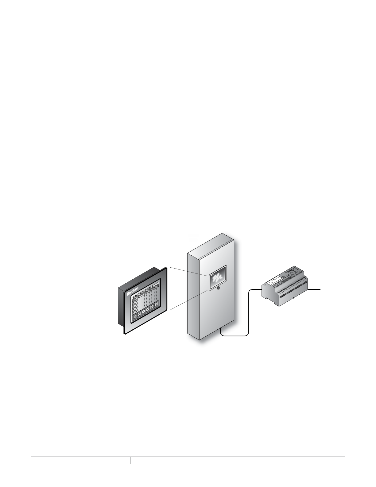
NGC-30
Panel
ane
NGC-UIT2
RS-485
Field located
RMM2
hem
ayc
R
To next
RMM2
Fig. 1.1 NGC-30 system, system example
1.1.2 CONTROL NGC-30
The Raychem NGC-30 measures temperatures with 3-wire, 100-ohm platinum RTDs connected
directly to the unit, or through optional Remote Monitoring Modules (RMM2 module). Each RMM2
module accepts up to eight RTDs. The RMM2 modules are typically located near the desired
measurement location (RTDs). Multiple RMM2 modules are networked over a single cable to
the NGC-30, significantly reducing the cost of RTD field wiring. The NGC-30 system supports
260 temperature inputs via the CRM/CRMS boards. Using RMM2 modules, an additional 128
temperature inputs can be supported for a maximum of 388 temperature inputs. With EMRs
and SSRs, the NGC-30 can be configured for On/Off, ambient sensing, and proportional ambient
sensing modes. Additionally, with SSRs, the panel can be configured for proportional, power
limiting, and soft start modes.
industrial heat tracing solutions
EN-RaychemNGC30UIT2Programming-AR-H5818602/16
4 / 84
Page 5

1.1.3 MONITORING
Both Raychem NGC-20 and Raychem NGC-30 can monitor multiple independent Electrical HeatTracing (EHT) parameters. The Raychem NGC-20 and Raychem NGC-30 monitor continuously
temperature, voltage, current and ground fault current leakage and report the values including alarms
to the UIT. An automated self-check feature is available where the systems periodically checks the
heating cables for faults and report the result to the UIT. This helps to avoid costly downtime. Dry
contact relays are provided for alarm annunciation back to a Distributed Control System (DCS).
1.1.4 GROUND-FAULT PROTECTION ACCORDING TO NORTH AMERICAN ELECTRICAL
CODE NEC STANDARD
National electrical codes require ground-fault equipment protection on all heat-tracing circuits.
Heat-tracing circuits equipped with Raychem NGC-30 controllers do not require additional
ground-fault detection equipment, simplifying installation and reducing costs. When applying the
IEC standards, additional RCD circuit breaker is required.
1.1.5 INSTALLATION
The Raychem NGC-30 system is configured with a User Interface Terminal (NGC-UIT2-EX) that has
LCD color touch-screen display technology. The NGC-UIT2-EX provides a user interface for easy
and efficient programming without keyboards or cryptic labels. The NGC-UIT2-EX model used
depends on the location of Raychem NGC-30 panel and the local environment.
Common NGC-UIT2 Interface and Programming
The term “NGC-UIT2” in this document refers to any of the available NGC-UIT2 models, regardless
of which model is actually installed. All NGC-UIT2s interface to the NGC-30-CRM, NGC-30-CRMS
(Card Rack Relay Control Modules), PLI (Power Line carrier Interface), and the RMM2 module
(Remote Monitoring Module). The three NGC-UIT2 versions described in Table 1.1 on page 5
all use the same wiring, system interface, and programming. The NGC-UIT2s differ only in the
environments in which they can be installed.
NGC-UIT2 Installed in Hazardous and Non-hazardous Indoor or Outdoor Panel Locations
If the panel is located in a hazardous/non-hazardous indoor or outdoor location, the NGC-UIT2-EX
model is required. This NGC-UIT2-EX model is specifically designed for these environments and
meets all applicable standards. The NGC-UIT2-EX model is installed locally on the Raychem NGC30 panel door.
NGC-UIT2 Installed Separately from the Panel Locations
If the user interface terminal needs to be mounted separately from the Raychem NGC-30 control
panel, such as when the panel is in a hazardous or difficult to access location, the NGC-UIT2ORD-R provides a wall-mount alternative for remote mounting in a nonhazardous (unclassified)
indoor or outdoor location.
Table 1.1 NGC-30 User Interface Terminals (UIT2s)
UIT2 type Area classification Usage
NGC-UIT2-EX Nonhazardous (Unclassified) Locations
Hazardous* Locations
Class 1 Div. 2, Groups A, B, C & D
Zone 2
NGC-UIT2-ORD-R Nonhazardous (Unclassified) Locations
• The NGC-UIT2-ORD-R must be
installed in a nonhazardous, indoor
or outdoor location.
• The NGC-UIT2-ORD-R connects
to NGC-30 panels using RS-485
communication wiring.
*Hazardous locations are defined by Article 500 of the National Electrical Code and Section 18 of the
Canadian Electrical Code.
Type 4
• (Indoors or Outdoors)
Type 4
• (Indoors or Outdoors)
industrial heat tracing solutions
EN-RaychemNGC30UIT2Programming-AR-H5818602/16
5 / 84
Page 6

1.1.6 COMMUNICATIONS
The NGC-UIT2 units can be networked to a host PC running Windows®-based Raychem
Supervisor client-server software for central programming, status review, and alarm
annunciation. NGC-UIT2s support the Modbus
or 10/100Base-T Ethernet communication interface.
®
protocol and are available with an RS-232, RS-485
1.1.7 COMPLETE SYSTEM
The Raychem NGC-30 is supplied as a complete system ready for field connections of power
wiring and temperature sensor input. Optional Power Distribution further enhances the reduction
of field wiring and labor to install.
1.1.8 THE Raychem NGC-UIT2-EX PROGRAMMING GUIDE
This Raychem NGC-UIT2-EX Programming Guide (H58186) assists in the set up and operation of
the Raychem NGC-20 and NGC-30 system.
The Raychem NGC-UIT software (version 4.x and higher), installed in the NGC-UIT2-EX (User
Interface Terminal), is designed to configure various Raychem devices.
This software version supports the:
1) Raychem NGC-20 controllers
2) Raychem NGC-30 Heating-Tracing Panels using:
a) NGC-30-CRM/-CRMS card rack modules with or without multiplexed RTD inputs via the
Raychem RMM2 module or RTD inputs via the Raychem PLI module.
b) MONI-RMC and RMM-DI modules for digital input and relay output signals.
It supports the RMC modules and RMM-DI for digital inputs and outputs as well.
The software provides several features to help configure and maintain the Raychem devices. This
document is not intended to provide detailed explanations of the specific features of each product,
but rather to show how to access various parameters within the devices using the Raychem NGC30 software. Please refer to specific detailed product use documentation:
• Raychem NGC-30 Installation Manual (H57878)
• Raychem NGC-UIT2 Modbus Protocol Interface Mapping for NGC-30 Systems (H57880).
1.2 VITAL INFORMATION
1.1.9 USER INTERFACE TERMINAL (NGC-UIT2) LANGUAGES
The languages supported by the NGC-UIT2 display are - and not limited to -: English, Spanish,
French, German, Russian, Chinese, Italian and Czech. The display language is selected by
accessing the System|Misc. screen. Refer to section 3.3.31 System | Misc Window on page 60 for
additional information.
This manual is a guide for the setup and operation of the Raychem NGC-30 and NGC-20 in
combination with the NGC-UIT2-EX user interface.
Important: All information, including illustrations, is believed to be reliable. Users, however,
should independently evaluate the suitability of each product for their particular application.
Pentair Industrial Heat Tracing Solutions makes no warranties as to the accuracy or completeness
of the information, and disclaims any liability regarding its use.
Pentair Industrial Heat Tracing Solutions only obligations are those in the Pentair Industrial Heat
Tracing Solutions Standard Terms and Conditions of Sale for this product, and in no case will
Pentair Industrial Heat Tracing Solutions or its distributors be liable for any incidental, indirect, or
consequential damages arising from the sale, resale, use, or misuse of the product. Specifications
are subject to change without notice. In addition, Pentair Industrial Heat Tracing Solutions
reserves the right to make changes—without notification to Buyer—to processing or materials
that do not affect compliance with any applicable specification.
industrial heat tracing solutions
EN-RaychemNGC30UIT2Programming-AR-H5818602/16
6 / 84
Page 7

1.3 LICENSE AGREEMENT
1.3.1 Raychem NGC-30 SOFTWARE – LICENSE AGREEMENT
This agreement is a legal agreement between you, “the end user”, and Pentair Industrial
Heat Tracing Solutions, LLC (“Pentair Industrial Heat Tracing Solutions”). BY INSTALLING OR
OTHERWISE ACCESSING THIS PROGRAM, YOU ARE AGREEING TO BECOME BOUND BY THE
TERMS OF THIS AGREEMENT. IF YOU DO NOT AGREE TO THE TERMS OF THIS AGREEMENT, DO
NOT INSTALL OR ACCESS THIS PROGRAM. IF INSTALLING OR OTHERWISE ACCESSING THIS
PROGRAM BY OPENING A SEALED DISK PACKAGE, PROMPTLY RETURN THE UNOPENED DISK
PACKAGE AND THE OTHER ITEMS (INCLUDING WRITTEN MATERIALS OR OTHER CONTAINERS)
TO THE PLACE WHERE YOU OBTAINED THEM.
1. GRANT OF LICENSE. The Raychem NGC-30 Software (the “Software”) is licensed, not
sold, to you for use only under the terms of this Agreement, and Pentair Industrial Heat
Tracing Solutions reserves any rights not expressly granted to you. Subject to the terms and
conditions of this Agreement, Pentair Industrial Heat Tracing Solutions grants to you a nonexclusive, nontransferable, limited license (without the right to sublicense others) to use
the one copy, including written materials if any, of the Software on a single computer at the
location (company and address) to which Pentair Industrial Heat Tracing Solutions issued
this copy of the Raychem NGC-30 Software. The Software is owned by Pentair Industrial Heat
Tracing Solutions LLC and is protected by United States copyright laws and international
treaty provisions. All copies made by you are subject to the terms and conditions of this
Agreement. The structure, organization and code of the Software are valuable trade secrets
and confidential information of Pentair Industrial Heat Tracing Solutions. You agree not to
modify, alter, merge, adapt, duplicate, distribute, translate, decompile, disassemble, reverse
engineer, create derivative works, copy for use on any other computer or at any other location,
or otherwise make this software available to any person or entity outside this location. The
Software is licensed only to you. In no event may you transfer, sell, sublicense, rent, assign
or transfer rights, lease, or otherwise dispose of the Software on a temporary or permanent
basis without the prior written consent of Pentair Industrial Heat Tracing Solutions. You agree
to use reasonable efforts to protect against the unauthorized copying and use of the Software
by others. You agree not to remove, disable or circumvent any proprietary notices or labels
contained on or within the Software.
2. OTHER RESTRICTIONS.
1. You may not sublicense, rent or lease the Raychem NGC-30 Software to anyone.
2. You agree to notify Pentair Industrial Heat Tracing Solutions promptly if “bugs” or seemingly
incorrect or anomalous behavior is discovered when using the Software.
3. You agree that the Raychem NGC-30 Software, including written materials (if any) and all
copies in whole or in part, will be destroyed or returned to Pentair Industrial Heat Tracing
Solutions at the written request of the Pentair Industrial Heat Tracing Solutions Product
Manager.
4. By installing or otherwise accessing the Raychem NGC-30 Software you acknowledge that
you have read and understood Pentair Industrial Heat Tracing Solutions’ Disclaimer of
Warranty and Limitation of Liability, set forth below.
5. You agree to use reasonable efforts to protect against the unauthorized copying and use the
Raychem NGC-30 Software by others.
3. DISCLAIMER OF WARRANTY. THE Raychem NGC-30 SOFTWARE AND ACCOMPANYING
WRITTEN MATERIALS ARE PROVIDED “AS IS” WITHOUT WARRANTY OF ANY KIND. THE
ENTIRE RISK AS TO THE RESULTS AND PERFORMANCE OF THE Raychem NGC-30 SOFTWARE
IS ASSUMED BY YOU. Pentair Industrial Heat Tracing Solutions DOES NOT WARRANT THAT
THE FUNCTIONS CONTAINED IN THE SOFTWARE WILL MEET YOUR REQUIREMENTS OR THAT
THE OPERATION OF THE SOFTWARE WILL BE UNINTERRUPTED OR ERROR-FREE, OR THAT
PROGRAM DEFECTS WILL BE CORRECTED.
4. LIMITED WARRANTY – MEDIA. THE MEDIUM ON WHICH THE PROGRAM IS ENCODED IS
WARRANTED TO BE FREE FROM DEFECTS IN MATERIAL AND WORKMANSHIP UNDER
NORMAL USE FOR A PERIOD OF SIXTY (60) DAYS FROM THE DATE OF DELIVERY TO YOU
AS EVIDENCED BY A COPY OF YOUR RECEIPT. ALTHOUGH Pentair Industrial Heat Tracing
Solutions BELIEVES THE MEDIA AND THE PROGRAM TO BE FREE OF VIRUSES, THE MEDIUM
AND THE PROGRAM ARE NOT WARRANTED TO BE VIRUS FREE. Pentair Industrial Heat
Tracing Solutions’ LIABILITY AND YOUR EXCLUSIVE REMEDY IF THE MEDIUM IS DEFECTIVE
industrial heat tracing solutions
EN-RaychemNGC30UIT2Programming-AR-H5818602/16
7 / 84
Page 8

OR INCLUDES ANY VIRUS SHALL BE PROMPT REPLACEMENT OF THE MEDIUM WITH A NEW
Raychem NGC-30 SOFTWARE PRE-ENCODED DISC.
5. EXCLUSION OF ALL OTHER WARRANTIES. EXCEPT AS EXPRESSLY PROVIDED ABOVE, Pentair
Industrial Heat Tracing Solutions DISCLAIMS ALL WARRANTIES, EITHER EXPRESS, IMPLIED
OR STATUTORY, INCLUDING BUT NOT LIMITED TO ANY WARRANTY OF MERCHANTABILITY OR
FITNESS FOR A PARTICULAR PURPOSE, EVEN IF Pentair Industrial Heat Tracing Solutions HAS
BEEN ADVISED OF SUCH PURPOSE. THIS AGREEMENT GIVES YOU SPECIFIC LEGAL RIGHTS.
SOME STATES OR COUNTRIES DO NOT ALLOW THE EXCLUSION OF WARRANTIES SO THE
ABOVE EXCLUSION MAY NOT APPLY TO YOU.
6. LIMITATION OF LIABILITY. THE ENTIRE RISK AS TO THE RESULTS AND PERFORMANCE OF
THE SOFTWARE IS ASSUMED BY YOU. IN NO EVENT SHALL Pentair Industrial Heat Tracing
Solutions, ITS AFFILIATES, DIRECTORS, OFFICERS, SHAREHOLDERS, EMPLOYEES OR
OTHER REPRE-SENTATIVES BE LIABLE FOR DAMAGES OF ANY KIND, INCLUDING WITHOUT
LIMITATION, ANY LOSS, DAMAGE, OR DELAY, OR FOR ANY LOST PROFITS, LOSS OF USE,
INTERRUPTION OF BUSINESS, OR FOR ANY COMPENSATORY, SPECIAL, INCIDENTAL,
CONSEQUENTIAL, INDIRECT DAMAGES (HOWEVER ARISING, INCLUDING NEGLIGENCE) OF
ANY KIND ARISING OUT OF OR IN CONNECTION WITH THE USE OF, OR THE INABILITY TO
USE, THE SOFTWARE OR THIS AGREEMENT (EVEN IF Pentair Industrial Heat Tracing Solutions
HAS BEEN ADVISED OF THE POSSIBILITY OF SUCH DAMAGES). FURTHER, IN NO EVENT
SHALL Pentair Industrial Heat Tracing Solutions, ITS AFFILIATES, DIRECTORS, OFFICERS,
SHAREHOLDERS, EMPLOYEES OR OTHER REPRESENTATIVES BE LIABLE TO YOU IN AN
AMOUNT GREATER THAN THE AMOUNT ACTUALLY PAID BY YOU, IF ANY, FOR THE SOFTWARE.
YOU FURTHER AGREE THAT REGARDLESS OF ANY STATUTE OR LAW TO THE CONTRARY, ANY
CLAIM OR CAUSE OF ACTION ARISING OUT OF OR RELATED TO USE OF THE SOFTWARE OR
THE TERMS AND CONDITIONS MUST BE FILED WITHIN ONE (1) YEAR AFTER SUCH CLAIM OR
CAUSE OF ACTION AROSE OR BE FOREVER BARRED.
7. INDEMNITY. To the extent allowed under federal and state law, you agree to indemnify and
hold Pentair Industrial Heat Tracing Solutions, its parents, subsidiaries, affiliates, officers,
employees, sponsors and partners harmless from any claim, loss, cost, expense, demand, or
damage, including reasonable attorneys’ fees, arising directly or indirectly out of (a) your use of,
or inability to use, the Software, (b) your activities in connection therewith, or (c) your breach of
this Agreement or violation of the rights of any other party.
8. TERMINATION. The license granted herein will automatically terminate without notice from
Pentair Industrial Heat Tracing Solutions if you fail to comply with any term or condition of this
Agreement. You agree, upon such termination, to remove the Raychem NGC-30 Software from
any memory and/or storage media or device, and to return the Raychem NGC-30 Software,
including all media and written materials, or destroy the same and certify such destruction
to Pentair Industrial Heat Tracing Solutions, along with any backup or other copies in your
possession.
9. COMPLETE AGREEMENT – MODIFICATION IN WRITING. This Agreement constitutes the
sole and complete understanding between the parties with respect to the Raychem NGC-30
Software and its use, and may not be varied except by a writing signed by an officer of Pentair
Industrial Heat Tracing Solutions. You agree that you may not rely on any representations
concerning the Raychem NGC-30 Software to the extent they vary from this Agreement, and
such representations, if any, will neither add to nor vary the terms of this Agreement.
10. CHOICE OF LAWS. This Agreement is governed by the laws of the State of California and the
United States, including U.S. Copyright Laws.
11. EXPORT LAWS. The Raychem NGC-30 Software may require a license from the U.S.
Department of Commerce or other governmental agency before it may be exported. The term
“export” includes many acts (such as transferring the Raychem NGC-30 Software to a foreign
citizen within the United States), in addition to sending or taking the Raychem NGC-30 Software
outside the United States. You agree to ascertain the necessary licensing procedures and
obtain any required licenses before exporting the Raychem NGC-30 Software. You also agree to
indemnify Pentair Industrial Heat Tracing Solutions and assume all financial responsibility for
any losses it may suffer if you do not comply with this paragraph.
12. GOVERNMENT RESTRICTED RIGHTS. User acknowledges that the Raychem NGC-30
Software has been developed at private expense and is provided with “Restricted Rights.”
Use, duplication or disclosure by the Government is subject to restrictions as set forth in
subparagraph (b)(3) and paragraph (c) of the Rights in Technical Data clause at 48 C.F.R.
252.227-7013, or subparagraphs (c)(1) and (2) of the Commercial Computer Software –
industrial heat tracing solutions
EN-RaychemNGC30UIT2Programming-AR-H5818602/16
8 / 84
Page 9

Restricted Rights clause at 48 C.F.R. 52.227-19, as applicable. This provision applies to the
Raychem NGC-30 Software acquired directly or indirectly by or on behalf of any government.
The Raychem NGC-30 Software is a commercial product, licensed on the open market at
market prices, and was developed entirely at private expense and without the use of any
government funds. Any use, modification, reproduction, release, performance, display, or
disclosure of the Raychem NGC-30 Software by any government shall be governed solely by
the terms of this Agreement and shall be prohibited except to the extent expressly permitted by
the terms of this Agreement, and no license to the Raychem NGC-30 Software is granted to any
government requiring different terms.
13. ASSIGNMENT. You may neither assign any right nor delegate any obligation under this
Agreement and attempted assignment or delegation shall be void. Pentair Industrial Heat
Tracing Solutions may freely assign this agreement and its rights and obligations there under
to any third party.
14. INVALID PROVISIONS. If any of the provisions of this provisions Agreement are invalid under
any applicable statute or rule of law, they are to that extent deemed omitted.
15. WAIVER. No failure or delay of Pentair Industrial Heat Tracing Solutions in exercising or
enforcing any right or provision of this Agreement shall constitute a waiver of such right
or provision, or any other right or provision hereunder. Furthermore, any waiver by Pentair
Industrial Heat Tracing Solutions of any right or provision of this Agreement shall not be
construed as, or constitute, a continuing waiver of such right or provision, or waiver of any
other right or provision of this Agreement.
16. HEADINGS. The section titles in this Agreement are for convenience only.
17. SURVIVABILITY. You agree that the terms and conditions of this Agreement shall survive any
termination of this Agreement and your rights to use the Software.
Should you have any questions concerning this Agreement, or if you desire to contact Pentair
Industrial Heat Tracing Solutions for any reason, please write to:
Pentair Industrial Heat Tracing Solutions
307 Constitution Drive
Menlo Park, CA 94025-1164
U.S.A.
1.4 USER RESPONSIBILITIES
The performance, reliability and safety of your heat-tracing system depend on proper design,
selection, and installation. The Raychem NGC-UIT2-EX Software will help you configure and
monitor a system that meets your requirements, but it is only a tool. It assumes that your input
is accurate, that you are familiar with heat-tracing system design and configuration, and that you
will ensure that all components of the heat-tracing system are installed, maintained and used
as intended. The configuration of the Raychem NGC-UIT2-EX Software should be reviewed by a
knowledgeable engineer to ensure it is appropriate for your application. Additional information
relating to safety, design, and installation is contained in Design Guides, Installation Manuals,
Data Sheets, and other literature available from Pentair Industrial Heat Tracing Solutions. Be sure to
consult these documents as needed.
1.5 SAFETY WARNINGS
There are important safety warnings which are shipped with Pentair Industrial Heat Tracing
Solutions products and that are also printed in the Raychem NGC-20 Installation Manual
(ML-RaychemNGC20CLE-IM-INSTALL130) and Raychem NGC-30 Installation Manual (H57878). Be
sure to read and follow these safety warnings to reduce the risk of fire, shock, or personal injury.
If you have any questions, contact your local representative or contact Pentair Industrial Heat
Tracing Solutions directly.
1.6 WARNING, ERROR AND ALARM MESSAGES
Under certain conditions, the Raychem NGC-30 program will alert the user with a warning or an
error message. These are typically either because the program cannot find an acceptable answer
based on user input, or because the user may need to take some additional action to ensure the
design requirements are completely met. These warnings and error messages are detailed on
page 52.
industrial heat tracing solutions
EN-RaychemNGC30UIT2Programming-AR-H5818602/16
9 / 84
Page 10
1.7 TECHNICAL SUPPORT
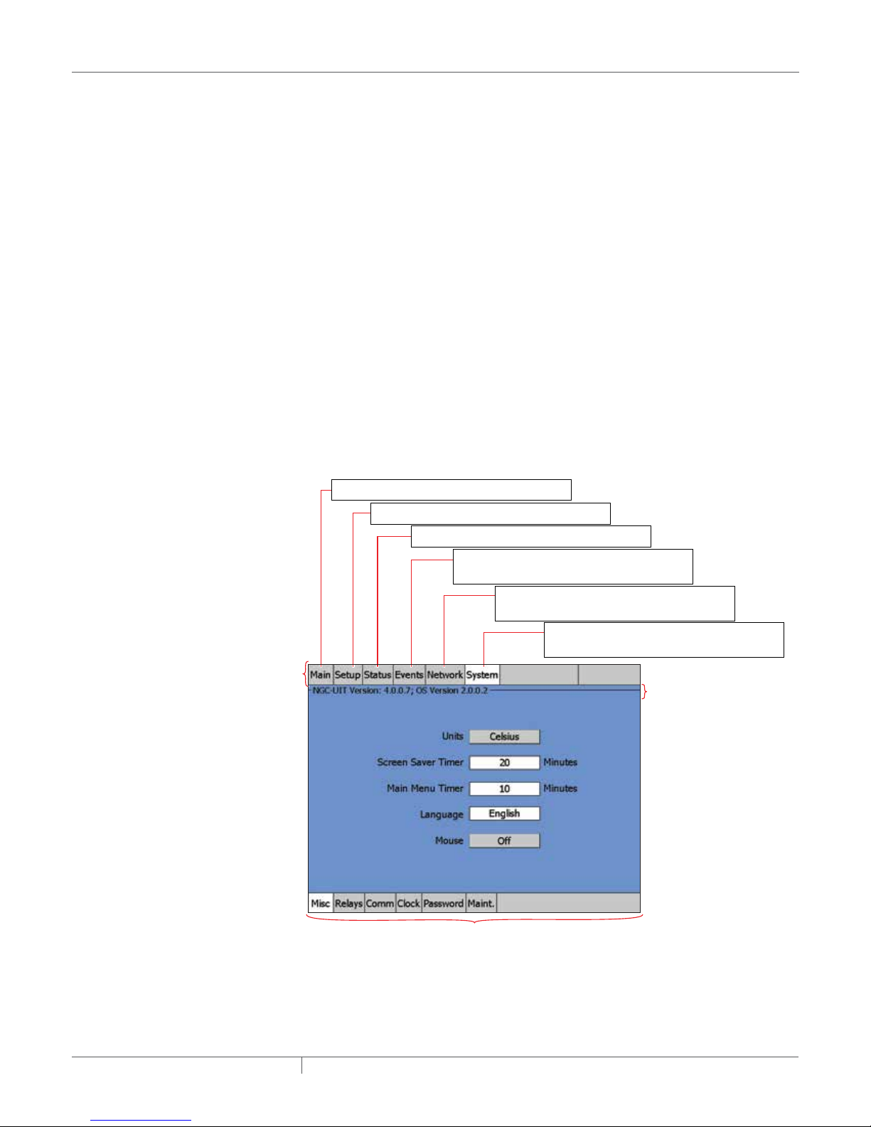
Menu
(changes with each main menu selected)
1.8 NAVIGATION
For technical support, contact your local representative, or contact Pentair Industrial Heat Tracing
Solutions directly:
Pentair Industrial Heat Tracing Solutions
7433 Harwin Drive
Houston, TX 77036
USA
Tel: 800-545-6258
Tel: 650-216-1526 (outside U.S.)
email: technicalsupport@pentairthermal.com
1.8.1 NAVIGATING BETWEEN WINDOWS
The top row of the window contains the main menu buttons, and the bottom row contains subsets
of those main menu buttons.
When asked to navigate between windows in this manual, simply press a combination of a Main
Menu | Submenu buttons.
For example in Step 1, the System | Misc window must be accessed. To perform this action, press
the System button on the top row. On the bottom row, press the Misc button.
On Setup and Status windows, a Status legend displays. This information shows what Device
address and Relay address have been assigned to a particular Circuit.
Main: Displays the status of all Circuits
Setup: Displays the setup parameters for a CircuitSetup: Displays the setup parameters for a Circuit
Status: Displays the status for a Circuit
Events: Displays the chronological history of
all events and alarms
Network: Displays the summariazation of the
device addresses and resources
System: Displays system wide (global) set-up
parameters for all Circuits
Main
Fig. 1.2 Navigation
industrial heat tracing solutions
Main Menu’s Sub-Menu
EN-RaychemNGC30UIT2Programming-AR-H5818602/16
Navigational
Header
10 / 84
Page 11
Main Window and Events/Alarms Navigation
Navigation Buttons
At the bottom of the Main Window and Events Window, the navigation buttons will appear once six
events have occurred. Use buttons to scroll up and down to view the status of the Circuits on the
Main Window, and on the Events/Alarms on the Events Window.
Shortcut: If a Circuit number is associated with an Event or Alarm, selecting it automatically sends
you to that circuit’s Status/Circuit window. This will help in troubleshooting.
When in the Main or Events|Alarms windows, press on any data field for a Circuit to see the Status
window for that Circuit.
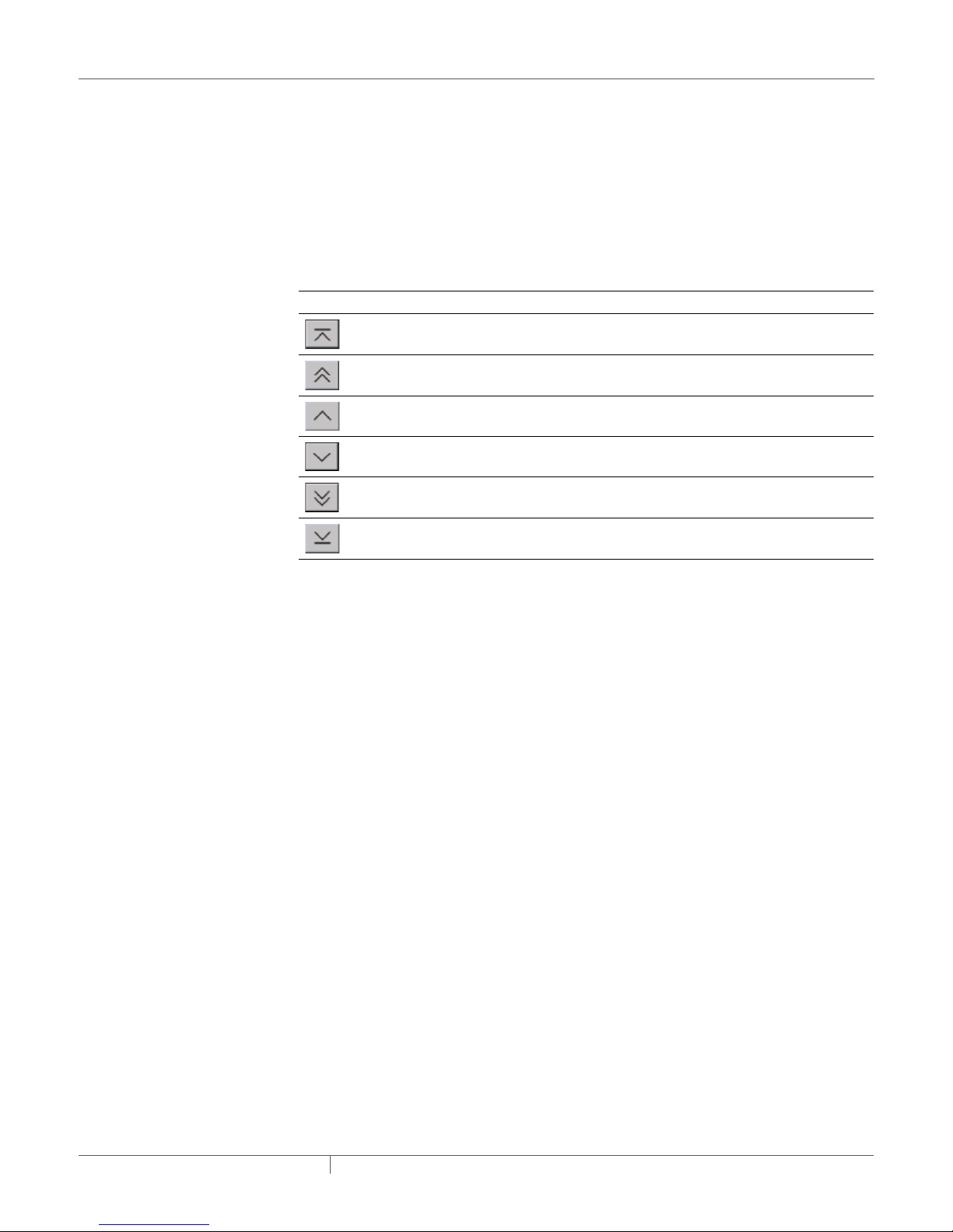
Table 1.2 Navigation Buttons
Top of list When selected, displays the first five Circuits of the
Main and the Events windows.
Page up When selected, displays the previous five Circuits of the
Main and the Events windows.
Move up one Circuit When selected, displays the previous Circuit on the
Main and the Events windows.
Move down one Circuit When selected, displays the next Circuit on the Main
and the Events windows.
Page down When selected, displays the next five Circuits of the
Main and the Events windows.
Bottom of list When selected, displays the last five Circuits of the
Main and the Events windows.
industrial heat tracing solutions
EN-RaychemNGC30UIT2Programming-AR-H5818602/16
11 / 84
Page 12
SECTION 2 BASIC CONFIGURATION QUICK START
The following gives an overview of how to implement a simple 4 Circuit system. For greater detail
and PLI module configuration, please go to Section 3 – Full Configuration on page 25.
2.1 AN EXAMPLE OF A SIMPLE 4 CIRCUIT SETUP
IMPORTANT: A Configuration Spreadsheet has been developed to assist in the collection of
specific
circuit (Circuit) details. This spreadsheet is located in Appendix E.
The following is a typical heat-tracing system for a four (4) Circuit Setup:
• Four (4) pipes (Pipe #1, Pipe #2, Pipe #3, Pipe #4)
• Four (4) heaters (one per pipe: Heater #1, Heater #2, Heater #3, Heater #4)
• Four (4) output relays (Relay #1, Relay #2, Relay #3, Relay #4) which control the heater’s
contactors
• Four (4) RTD temperature sensors (RTD #1, RTD #2, RTD #3, RTD #4)
• Four (4) On/Off control modes
This is the first window that appears when the program loads.
Fig. 2.1 Main window
industrial heat tracing solutions
EN-RaychemNGC30UIT2Programming-AR-H5818602/16
12 / 84
Page 13
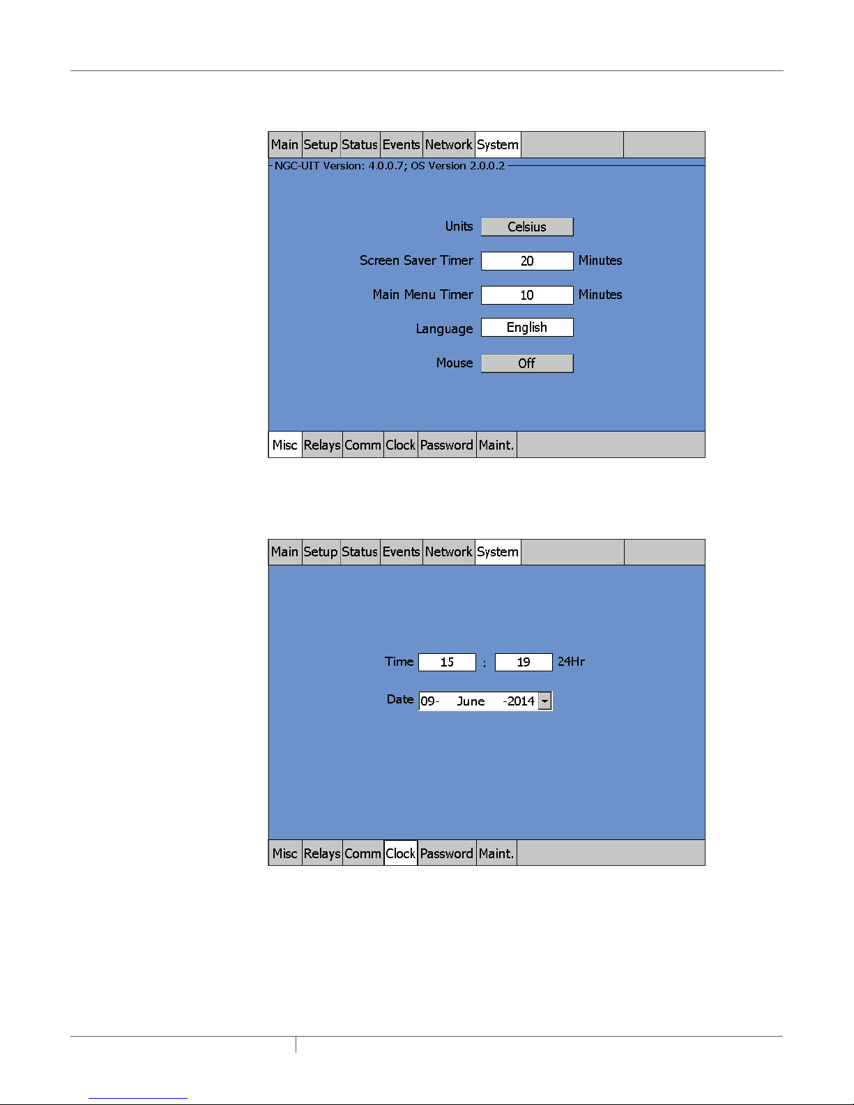
Step 1: Setting up Units and Language
Go to the System | Misc window and enter the appropriate Units and Language.
Fig. 2.2 System|Misc window
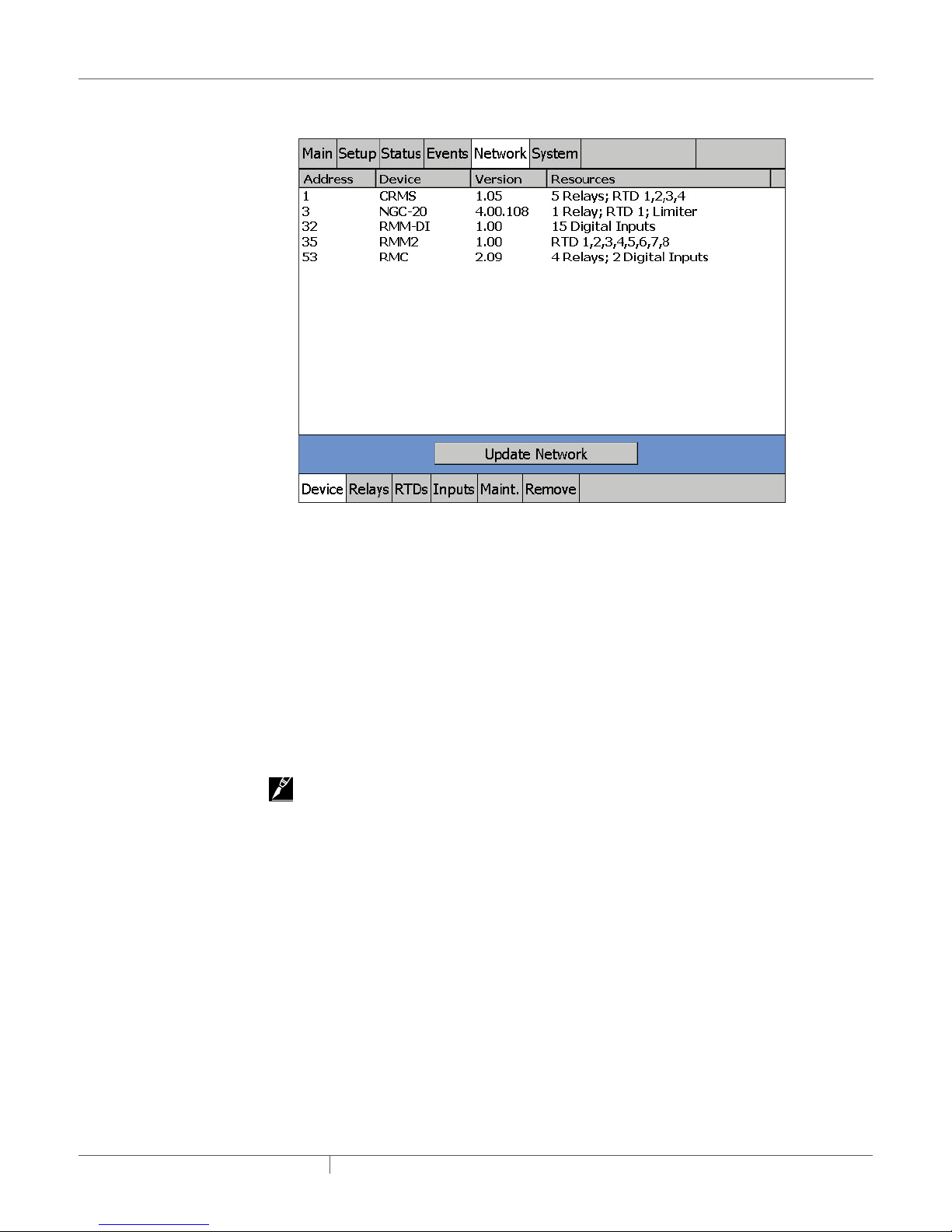
Step 2: Setting Time and Date
Go to the System | Clock window and set the time and date
Fig. 2.3 System | Clock window
industrial heat tracing solutions
EN-RaychemNGC30UIT2Programming-AR-H5818602/16
13 / 84
Page 14
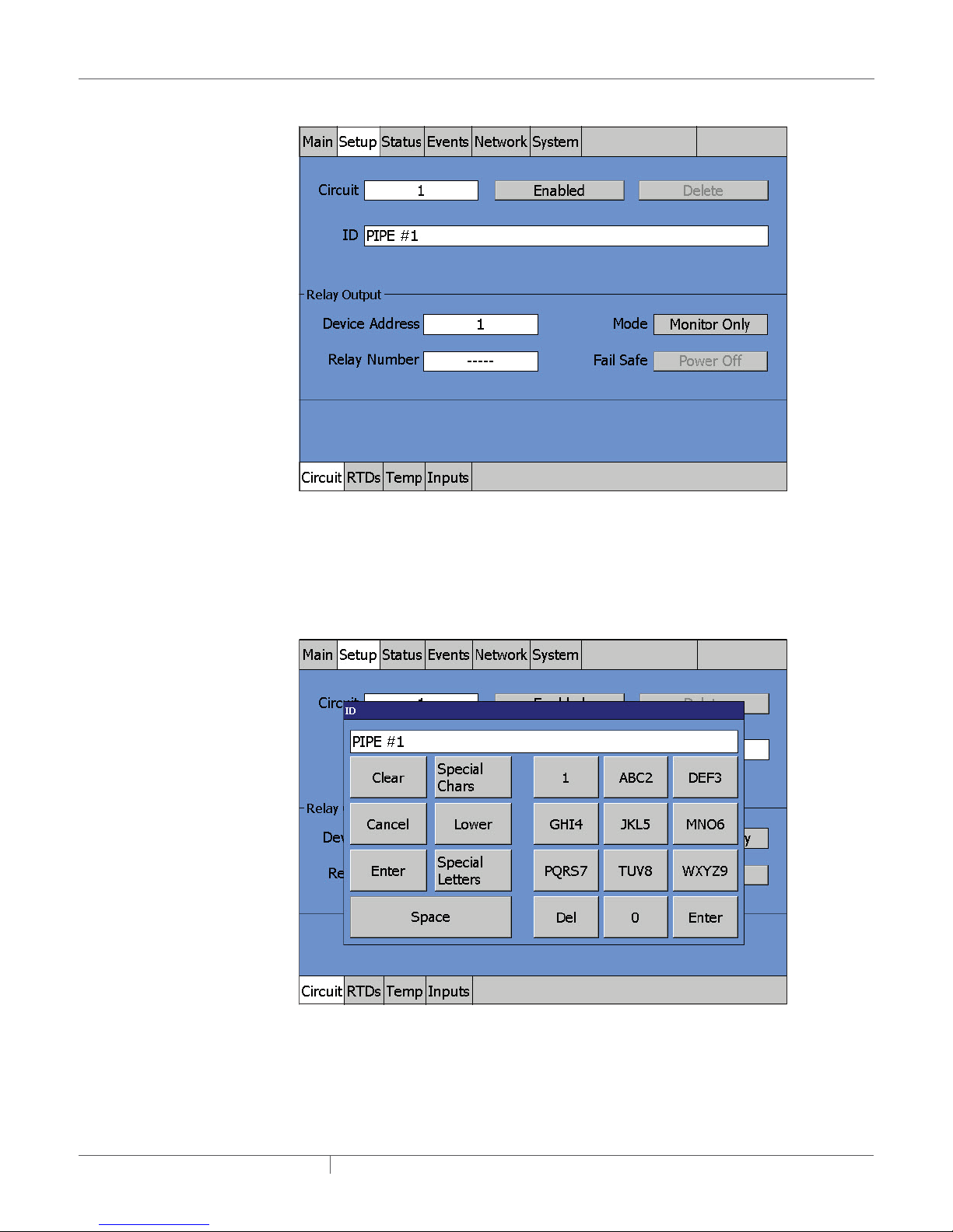
Step 3: Setting Up the Network for Device(s)
Go to the Network | Devices window.
Fig. 2.4 Network | Devices window
Press “Update Network”. The NGC-UIT2 will scan all NGC-30-CRMs/-CRMSs, PLI modules, NGC20 controllers, RMC modules, RMM-DI modules and/or RMM2 modules into the network database.
Once the database exists, no further scanning is done. A device address is the number assigned
via the rotary switches on the NGC-30-CRM-CRMS, PLI, RMC, RMM-DI modules or RMM2 module
circuit board. See the Raychem NGC-30 Installation Manual (H57878) for more information.
In this example the system found 4 devices. These are:
1) A CRMS board with 4 RTDs installed on position 1, 2, 3, and 4
2) A Raychem NGC-20 controller with 2 RTD connected directly to the controller. The Raychem
NGC-20 is equipped with a limiter (which has its own temperature sensor).
3) RMM with 7 RTDs connected to it.
4) RMM-DI with 15 digital inputs
5) RMC with 2 relays outputs and 2 digital inputs.
IMPORTANT: See page 56 for additional information.
Step 4: Setting up a Circuit
In this manual we set up a circuit on the NGC-30-CRMS controller. For the Raychem NGC-20
controller the same steps can be followed. As the Raychem NGC-20 controller is not identical to
the Raychem NGC-30 controller, it is possible that the screens differ.
industrial heat tracing solutions
EN-RaychemNGC30UIT2Programming-AR-H5818602/16
14 / 84
Page 15
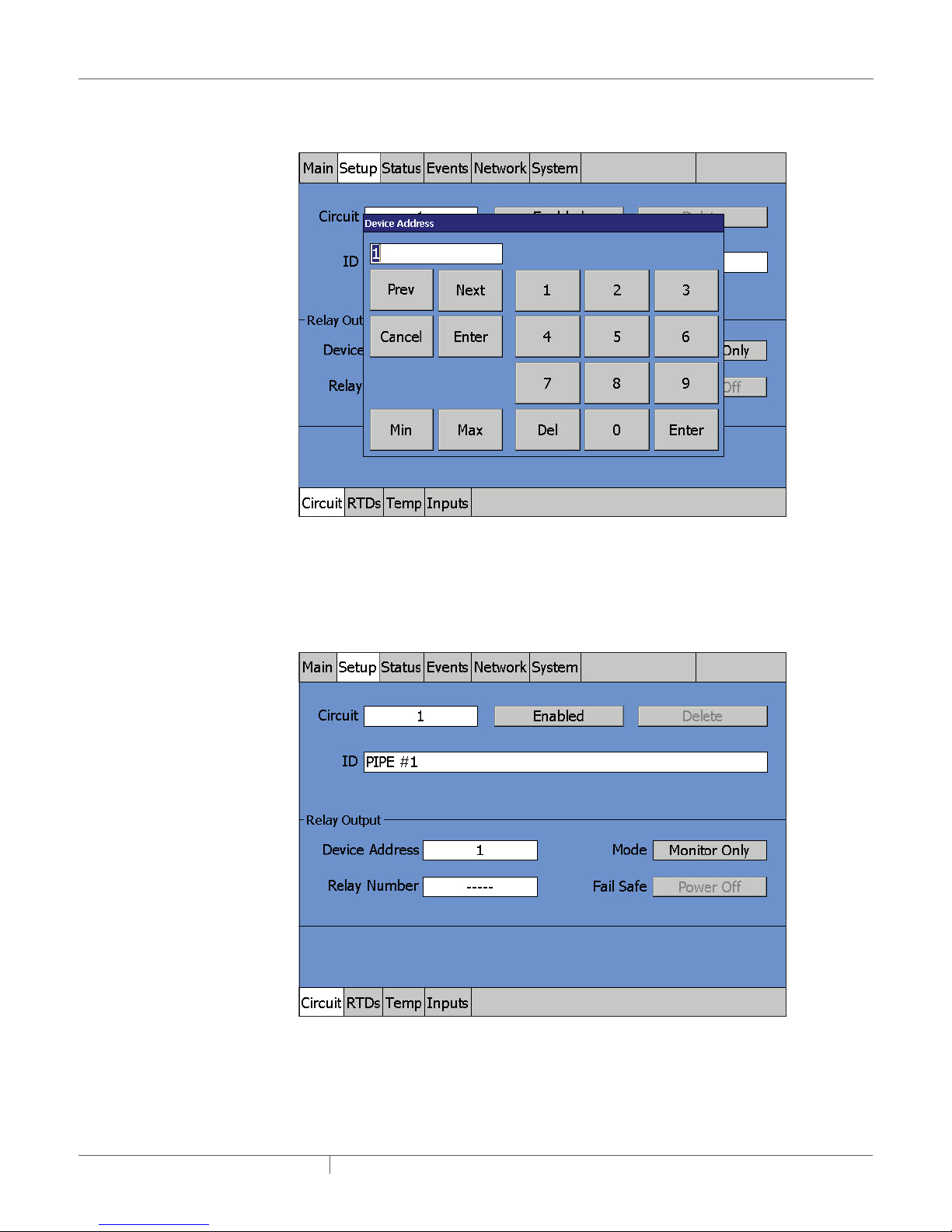
Step 4A: Go to Fig. 2.6 | ID pop-up window
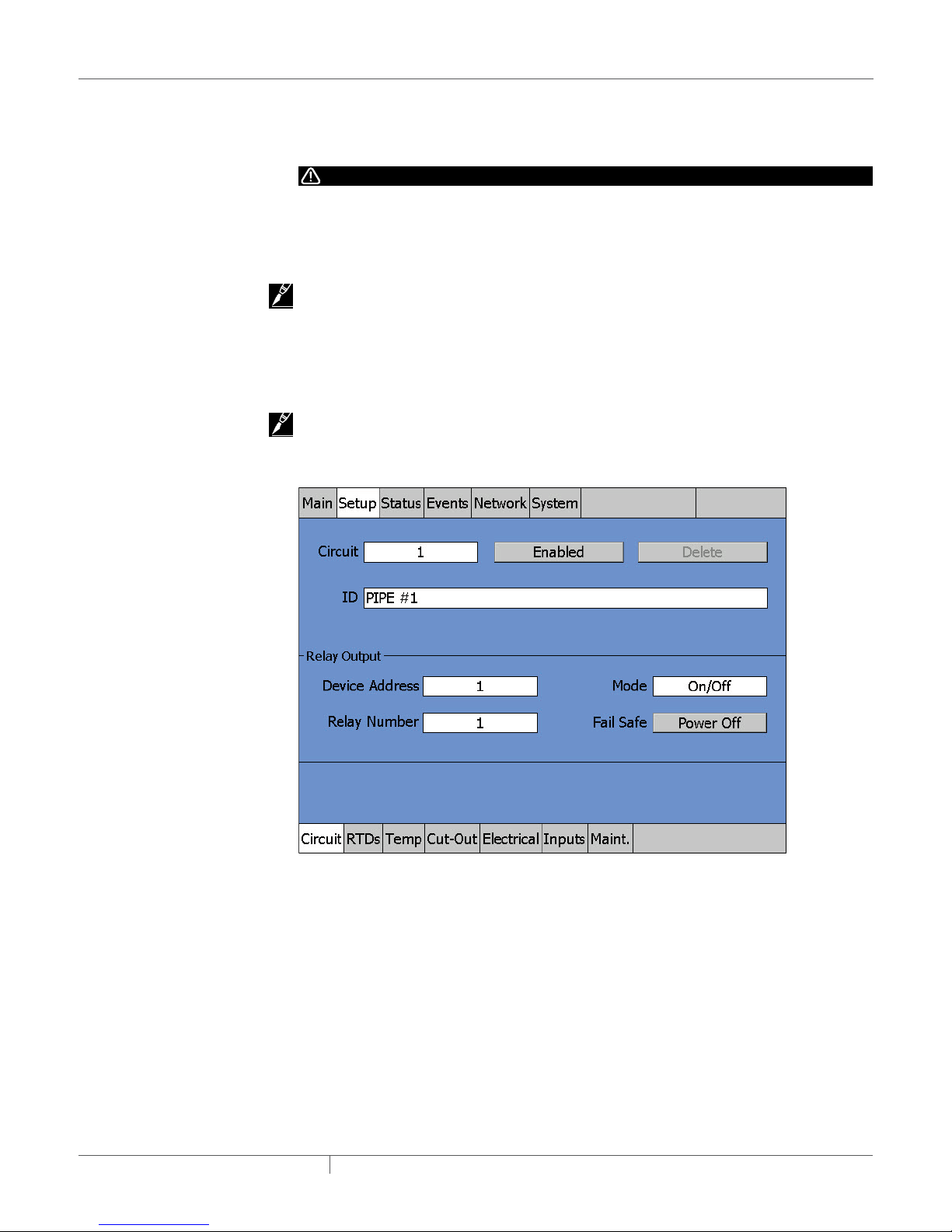
Fig. 2.5 Setup|Circuit window
At initial start-up, the Setup|Circuit window automatically displays Circuit 1.
Step 4B: Press on the ID field and a pop-up window appears
Fig. 2.6 ID pop-up window
• The pop-up window is a text-editing window that works similar to cell phone text messaging.
There are selection keys for Upper Case Letters, Lower Case Letters, and Special Characters.
The keypad portion allows you to enter text by pushing the appropriate keys.
• For this example, Pipe #1 was entered for the ID tag.
• Press Enter when done.
industrial heat tracing solutions
EN-RaychemNGC30UIT2Programming-AR-H5818602/16
15 / 84
Page 16
Step 4C: Press on the Device Address field
Fig. 2.7 Device Address window
• A numeric entry pop-up window appears. Type in the device address (in this case, 1) for this
Circuit and press Enter. (See page 56 for more on device addresses.)
Step 4D: Press on the Relay Number field
Fig. 2.8 Relay number window
industrial heat tracing solutions
EN-RaychemNGC30UIT2Programming-AR-H5818602/16
16 / 84
Page 17
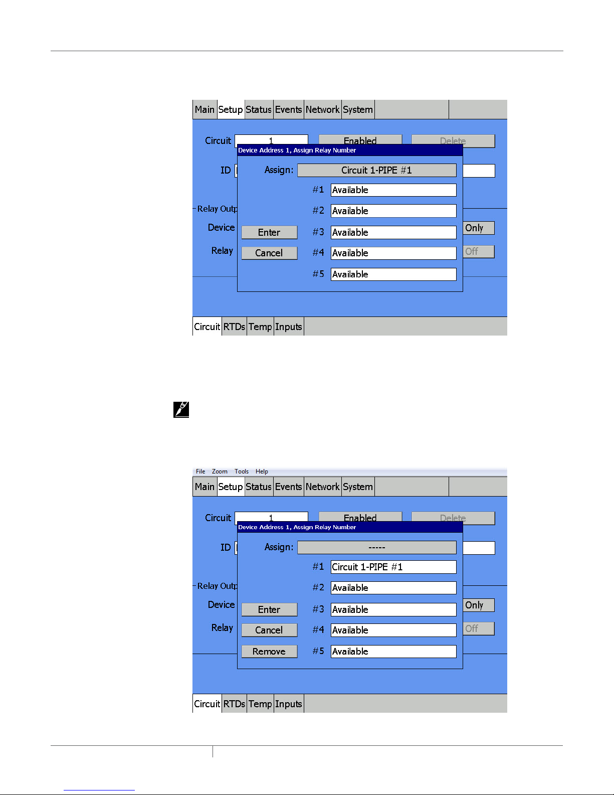
Step 4D continued: This window shows the pop-up window prior to any Relay assignment
Fig. 2.9 Pop-up window prior to any Relay Assignment
• Press on the word “Available” to the right of #1 to assign Relay 1 as the output device for Circuit 1.
IMPORTANT: The window will always display which Relays are still available on this device for
Circuit assignment.
Step 4D continued: Press Enter after Relay assignment to return to the Setup window
Fig. 2.10 Device Address, Assign Relay Number window
industrial heat tracing solutions
EN-RaychemNGC30UIT2Programming-AR-H5818602/16
17 / 84
Page 18
• Press Enter.
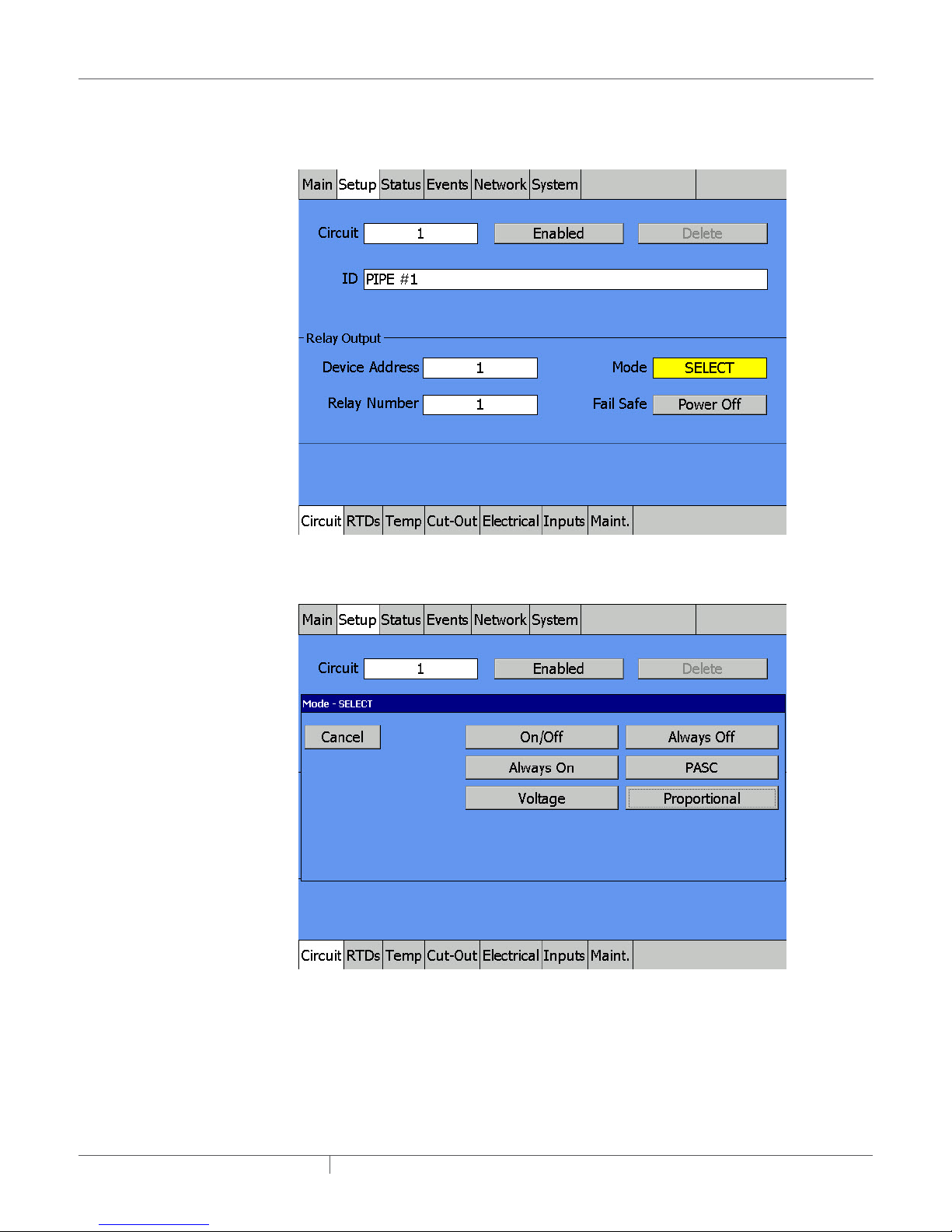
Step 4E: Press on the Mode field and a pop-up window appears, showing all available
control modes
Fig. 2.11 Mode window pop-up
Step 4E (continued): Pop-up window for control mode appears
Fig. 2.12 Mode - Select window
At the Mode - SELECT window:
• This pop-up window lets you select a Circuit’s basic operating mode. The NGC-30-CRMS, used
in this example, has the following Control modes available: On/Off, Always On, Always Off,
PASC, Voltage and Proportional.
• The On/Off mode is a simple setpoint/dead band operation.
• Press On/Off to select this control mode and return to the Setup Circuit window.
industrial heat tracing solutions
EN-RaychemNGC30UIT2Programming-AR-H5818602/16
18 / 84
Page 19
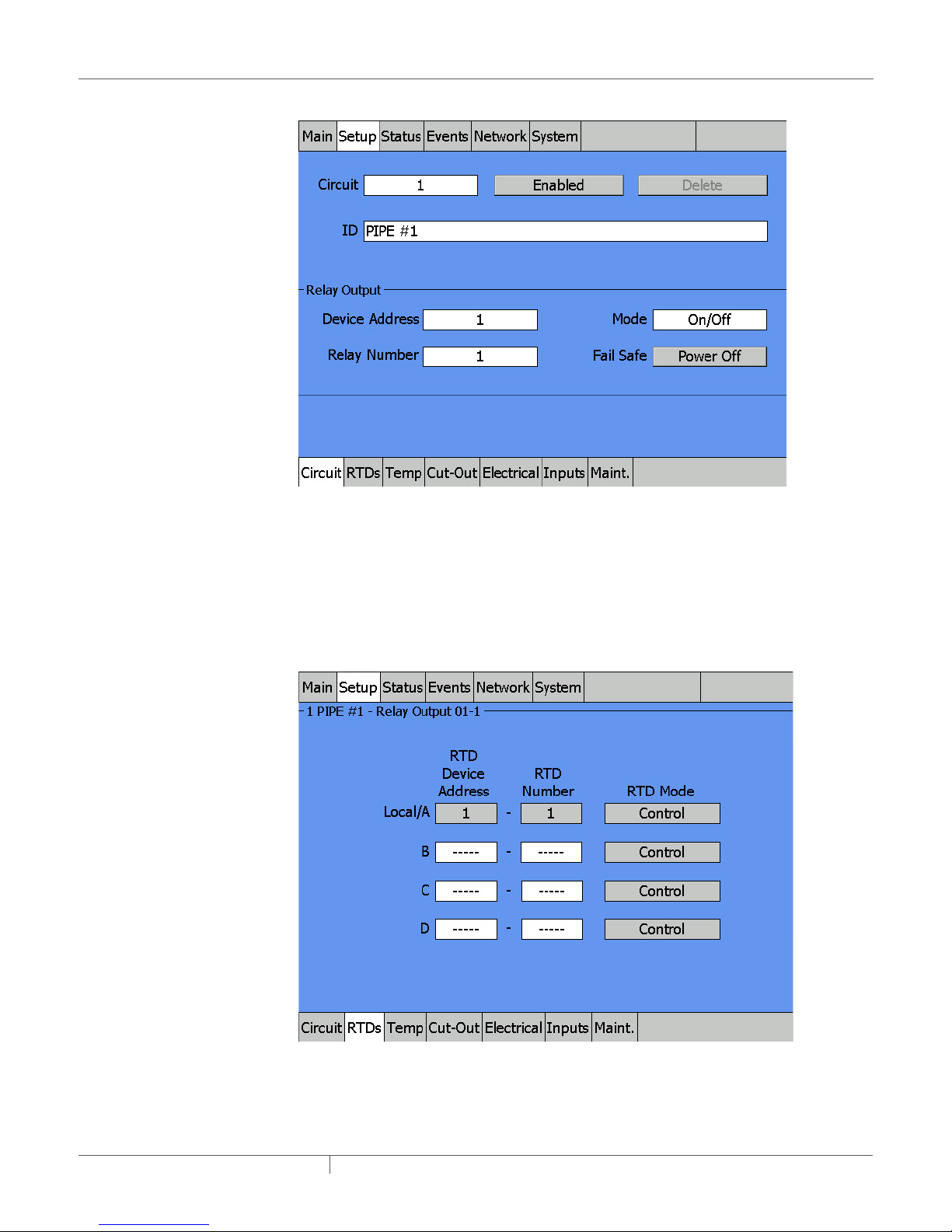
Step 5: Review the Fail Safe setting
Fig. 2.13 Setup|Circuit window and Fail Safe button
At the Setup|Circuit window:
• Pressing the Fail Safe toggle button alternates the Fail Safe mode between Power Off and
Power On. This selection tells the NGC-30-CRM/-CRMS if the heater should be turned on or off
if all of the RTD(s) for this Circuit fail.
• If the main concern is to prevent pipes from freezing, then Power On is a good choice. However,
if the heater is oversized and overheating is a concern, then Power Off could be a better choice.
Step 6: Go to Setup | RTDs window
Fig. 2.14 Setup | RTDs window
industrial heat tracing solutions
EN-RaychemNGC30UIT2Programming-AR-H5818602/16
19 / 84
Page 20
At the Setup|RTD window:
• The Raychem NGC-30 program first checks to see if the default RTD is available. On any
NGC-30-CRM/-CRMS board, the first RTD input is automatically coupled with the first relay
output; the second RTD is linked with the second output relay, etc. (In the case an RMC - RMM2
combination is chosen, then the user must define himself which RTD Device address is coupled
with the RMC output.)
• Here an RTD has been connected to the RTD 1 terminal block, so the RTD set-up window
indicates the default assignment is already completed.
• There are three blank slots available so you can assign additional RTDs to this output relay. You
may desire additional RTDs if you need a more exact temperature sampling for a temperaturesensitive fluid. If you assign additional RTDs, the lowest RTD value from the list will be used for
control temperature.
• Each of the four RTDs can be independently set as Control or Monitoring only sensor. If you are
using a PLI module with SES-CONT sensors, an additional Continuity mode will be available.
See Section 3 for more details.
• See page 33 for information on how to set up additional RTDs. For this simple Circuit Quick
Start example, the default set-up RTD is used.
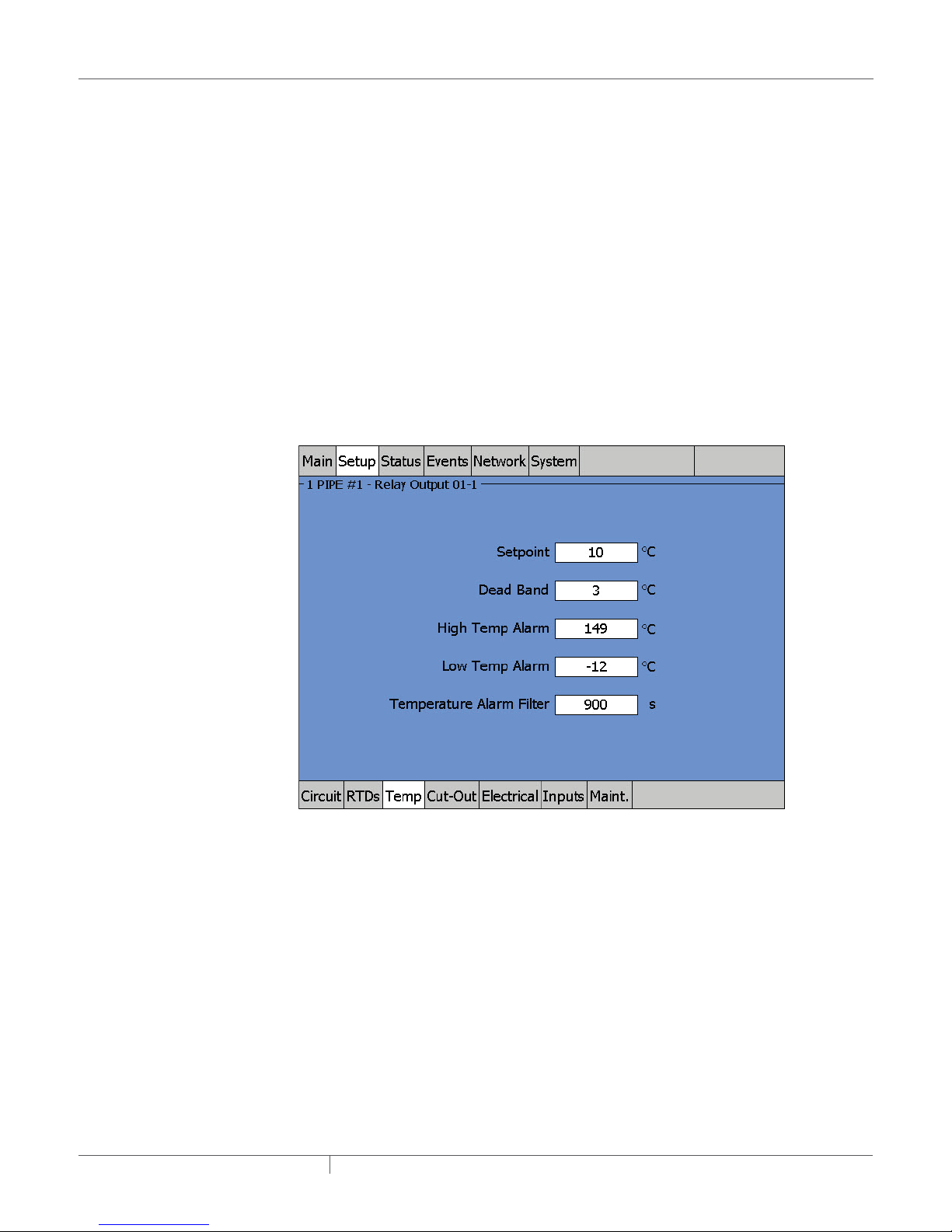
Step 7: Go to the Setup | Temp window
Fig. 2.15 Setup | Temp window
At the Setup|Temp window:
• Input the Setpoint, Dead Band, High Temp Alarm, and Low Temp Alarm by pressing on each of
the four numeric fields in turn.
• For this example, the Setpoint temperature is 10°C, a dead band of 3°C and high and low
temperature alarms at 149°C and -12°C respectively.
• Use the default value of 900 seconds (15 minutes) for the Temperature Alarm Filter (time delay
before the NGC-30 reports any temperature alarm) and the default value of Disable for the High
Temp Cut-Out. To implement the High Temp Cut-Out feature. See “High Limit Cut-Out Entry
Field” on page 36.
industrial heat tracing solutions
EN-RaychemNGC30UIT2Programming-AR-H5818602/16
20 / 84
Page 21
Step 8: Go to Setup | Electrical
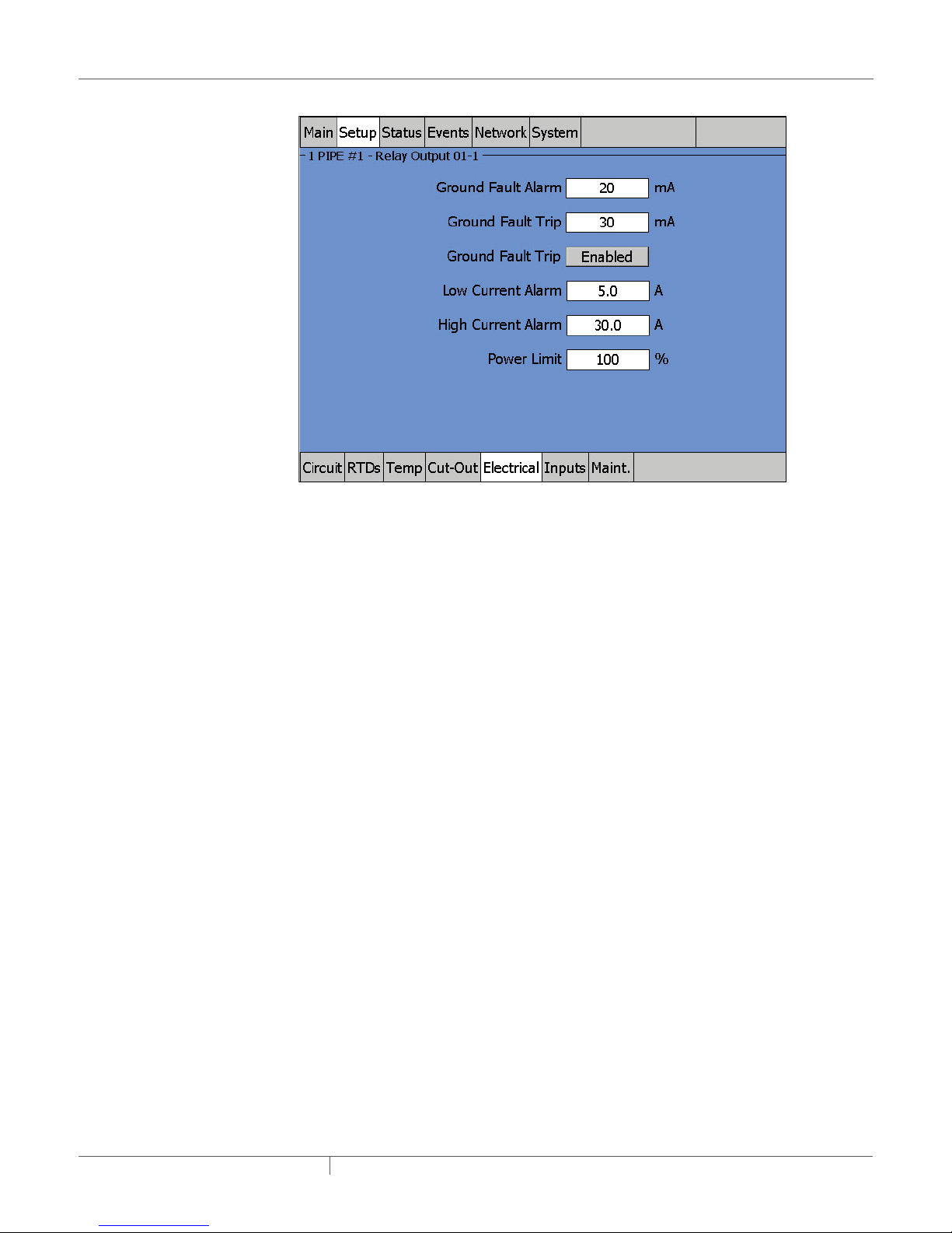
Fig. 2.16 Setup | Electrical
At the Setup | Electrical:
• Input the Ground-Fault Current Alarm and Ground-Fault Current Trip by pressing each of the
two numeric fields in turn.
• For this example, the Ground-Fault Current Alarm and Ground-Fault Current Trip levels are set
to 20 mA and 30 mA respectively.
– At less than 20 mA, the Raychem NGC-30 program takes no action. At 20 mA or more
leakage, an alarm is indicated and logged to the Events List.
– At 30 mA the output relay assigned to this Circuit is tripped off.
High Voltage Alarm Entry Screen
If the voltage monitoring module measures line voltage above this threshold, the NGC-UIT2
generates an alarm.
Range: 50 – 305 V
Default: 270 V
Low Voltage Alarm Entry Screen
If the voltage monitoring module measures line voltage below this threshold, the NGC-UIT2
generates an alarm.
Range: 50 – 305 V
Default: 90 V
industrial heat tracing solutions
EN-RaychemNGC30UIT2Programming-AR-H5818602/16
21 / 84
Page 22
• Input the High Current Alarm and Low Current Alarm by pressing each of the two numeric
fields in turn. For this example, High Current Alarm is set to 30 A, and Low Current Alarm is set
to 5 A.
WARNING:
Fire Hazard. A ground-fault alarm means the heating cable has been damaged or improperly
installed and must not be ignored. Disabling the ground-fault trip function reduces safety and
could result in sustained electrical arcing or fire. To minimize the risk of fire if the alarm activates,
shut off the power and repair the system immediately
IMPORTANT: Setting 0 for both High and Low Current Alarms completely deactivates the Current
Alarm function.
• Power Limit – This is enabled only when SSR control devices are detected (NGC-30-CRMS
panel). A Power Limit setting less than 100% will limit the “on-time” of a constant wattage
heater to the percentage indicated in the entry field. This has the effect of lowering the amount
of power that the heater can produce.
IMPORTANT: Power Limiting is not recommended if self-regulating heaters are installed.
Step 10: Enable or Disable the Circuit
Fig. 2.17 Circuit 1 enabled
At the Setup|Circuit window with Circuit #1 selected:
• By default, once you program a Circuit, it immediately begins to control the heater based on the
input information.
• If you do not want this Circuit to activate until all Circuits are programmed, go to Setup | Circuit
window and press the Enabled toggle button once, which disables the Circuit. To re-Enable,
press the Enable/Disable button again.
industrial heat tracing solutions
EN-RaychemNGC30UIT2Programming-AR-H5818602/16
22 / 84
Page 23
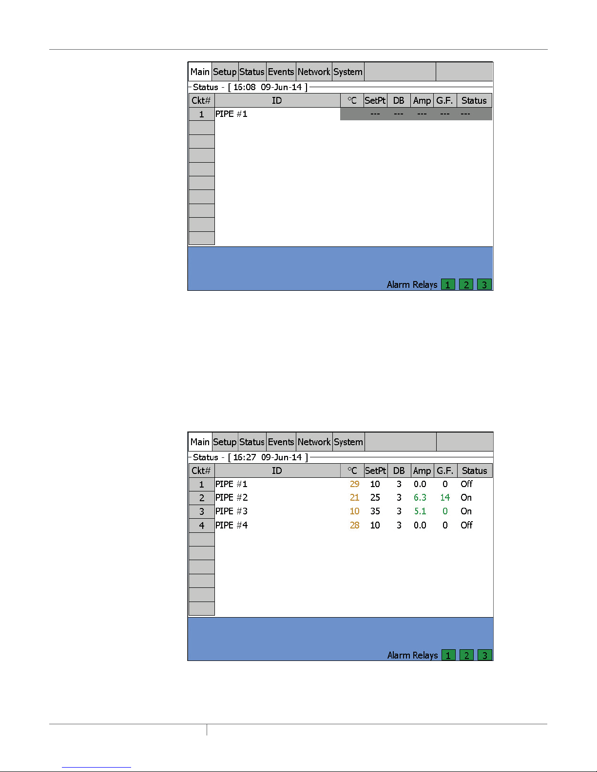
Fig. 2.18 Circuit 1 disabled
At the Main status display with Circuit #1 disabled:
• On the Main menu window, any Disabled Circuit is grayed out as above.
2.2 SETTING UP ADDITIONAL CIRCUITS
Follow Steps 4 through 10 above to set-up each additional Circuit.
2.3 CIRCUITS 14 SETUP COMPLETE CONFIRMATION
After completing the Setup for Circuits 1, 2, 3, and 4, and Circuits are Enabled, go to the Main
window to confirm all Circuits are activated and working properly.
Fig. 2.19 Main status window for confirmation
industrial heat tracing solutions
EN-RaychemNGC30UIT2Programming-AR-H5818602/16
23 / 84
Page 24

2.4 STARTING THE NGC30
2.4.1 SYSTEM REQUIREMENTS
The minimum configuration to use the Raychem NGC-30 software is:
• Raychem NGC-UIT2 hardware
• At least one of the following:
– NGC-30-CRM/-CRMS
– RMM2 Remote Monitoring Module
– RMC Module
– NGC-20 Controller
Maximum optional equipment configuration:
• Up to 52 Heat Trace Controller Boards (total count in any combination)
– NGC-30-CRM
– NGC-30-CRMS
• Up to 16 RMM2 modules (8 channel RTD multiplexing hubs)
• Up to 4 PLI modules (127 RTDs if SES/SPC transmitters are used, or 255 RTDs if 700-TT
transmitters are used)
• Up to 247 NGC-20 controllers
• Up to 247 RMM-DI modules
Total combination of output devices including NGC-30-CRM/-CRMS, NGC-20 and RMC DO cannot
exceed 260 circuits.
2.4.2 INITIAL SETUP
The Raychem NGC-30 software is designed to run only on the NGC-UIT2 hardware platform.
Prior to shipment, the Raychem NGC-30 software is installed into a nonvolatile area of the NGCUIT2 memory. During the initial power-up, you will see a blue background “splash” window for
approximately 30 seconds as the system software is loaded and initializes.
industrial heat tracing solutions
EN-RaychemNGC30UIT2Programming-AR-H5818602/16
24 / 84
Page 25
SECTION 3 FULL CONFIGURATION
3.1 SETTING THE NETWORK FOR DEVICES
Go to the Network|Device window.
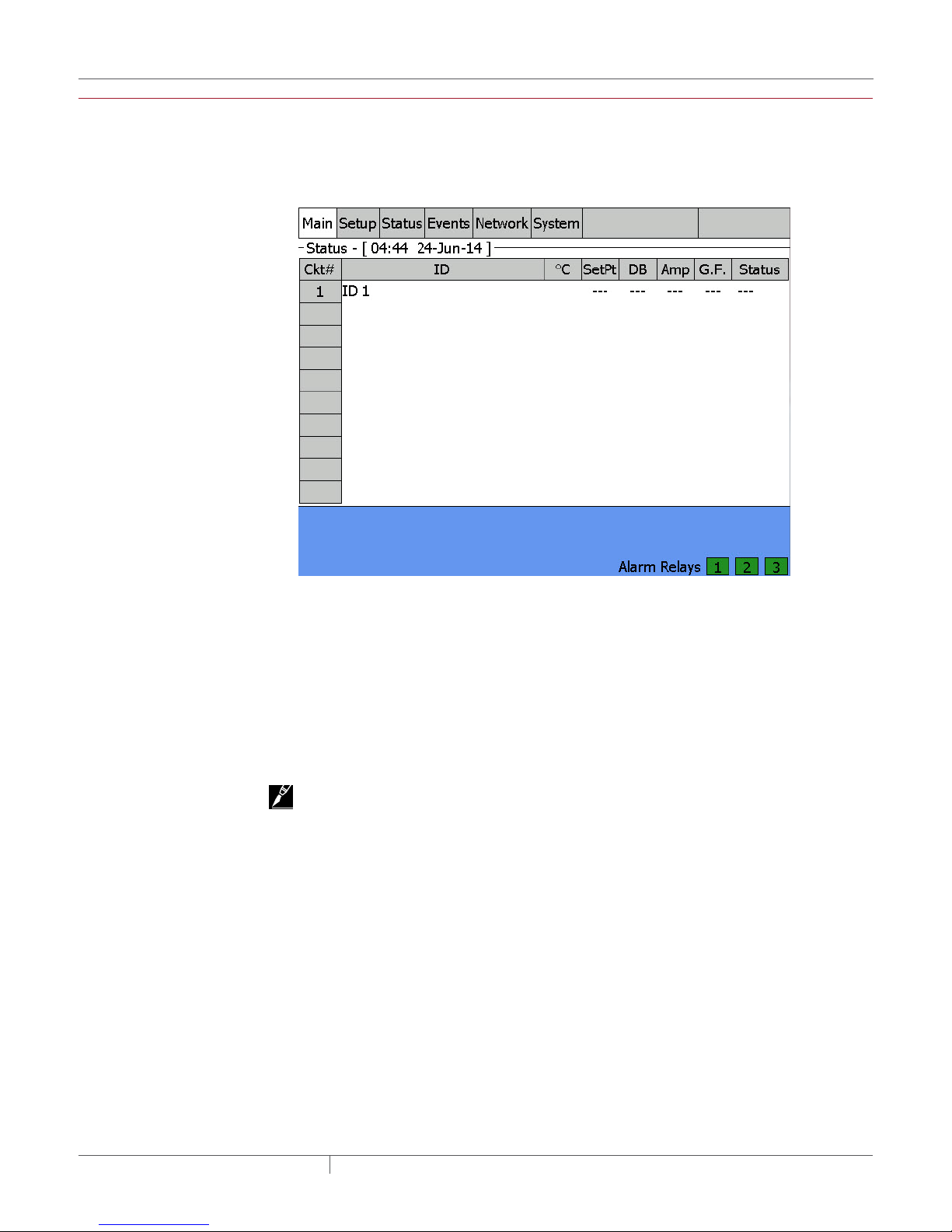
For the very first time, the Network screen will be blank. See below:
Fig. 3.1 Initial Network|Device window
Press "Update Network" and scan all NGC-30-CRM/-CRMS boards, RMM2 module and others
into the Network database. The Device Addresses for these modules will be scanned and a
database will be created. A device address is the number assigned via the rotary switches on the
NGC-30-CRM/-CRMS board, RMM2 module, PLI Module, RMC module and RMM-DI module. If an
expected device does not appear on the list after the scan is complete, it is most likely physically
disconnected from the RS-485 network wiring, or is not powered. Troubleshoot and verify all
network and power connections.
Once the database exists, no further scanning is done unless the system is forced to update the
network by activating the "Update Network" button.
IMPORTANT: If a new external hardware device is added after the initial scan, you must initiate a
manual scan by going to the Network|Devices window and pressing the "Update Network" button.
industrial heat tracing solutions
EN-RaychemNGC30UIT2Programming-AR-H5818602/16
25 / 84
Page 26

If a PLI (Power Line Carrier Interface) module is detected in the scanning process, a pop-up
window will open, asking whether the PLI Mode should be changed from the default mode of
PLI-SES/SPC to the PLI-TT. If a SES or SPC Transmitter is connected to the PLI module, the
option "NO" should be selected. The NGC-30 UIT2 indicates this PLI as PLI-SES/SPC. If a 700-TT
Transmitter is connected to the PLI module, the option "YES" should be selected. The NGC-30
UIT2 indicates this PLI as PLI-TT.
Fig. 3.2 Set PLI Mode
IMPORTANT: The NGC-30 Control System can support up to 4 PLI Modules. Each PLI module can
support up to 127 SES or SPC transmitters and up to 255 700-TT transmitters. The SES/SPC and
700-TT transmitters are not compatible and can not be connected to the same PLI module
The Network will then be updated with the connected devices, in this case with one NGC-30-CRMS
board, one RMM2 and one PLI-SES/SPC modules.
Fig. 3.3 Connected Network|Devices window
industrial heat tracing solutions
EN-RaychemNGC30UIT2Programming-AR-H5818602/16
26 / 84
Page 27

When a PLI module is detected in the Update Network process, the PLI tab will be added to the
Channel
GF = Ground fault
Network and Setup Sub-Menus.
IMPORTANT: For CRM/CRMS boards and RMM2 modules, the Resources Column indicates the
RTDs that are available for use in the Setup|RTD Screen. However, the Resources Column for PLISES/SPC or PLI-TT indicates the maximum number of RTDs that could be used. Please refer to
heater isometric drawings for each circuit for the assigned transmitters/RTD addresses to each
circuit.
3.1.1 MAIN WINDOW
After the first system scan
3.2 SOFTWARE ORGANIZATION
Fig. 3.4 Main status window
The Raychem NGC-30 is organized around the concept of control circuits, or simply “Circuits” as
they are called in the UIT2 windows. A typical Circuit consists of one output relay device, one RTD
sensor input, and one set of control parameters as shown below.
has been completed, the main window appears.
LC
Local
RTD
Local
RTD
Local
RTD
Local
RTD
Local
RTD
NGC-30-CRM/-CRMS Board
1
2
3
4
5
GF
LC
GF
LC
GF
LC
GF
LC
GF
LC = Line current
Output
Relay 1
Output
Relay
Output
Relay
Output
Relay
Output
Relay
Fig. 3.5 Simple control circuit
industrial heat tracing solutions
EN-RaychemNGC30UIT2Programming-AR-H5818602/16
27 / 84
Page 28

Channel
Local/A
RMM2 RMC RMM-DI
RTD
Local
RTD
Local
RTD
Local
RTD
Local
RTD
The Raychem NGC-30 software can manage up to 260 Circuits similar to that depicted above.
The control Circuit concept is not limited to the simple arrangement shown above. Multiple input
circuits and “monitor only” circuits are possible as depicted on the following page.
LC
1
2
3
4
5
GF
LC
GF
LC
GF
LC
GF
LC
GF
Output
Relay 1
Output
Relay
Output
Relay
Output
Relay
Output
Relay
NGC-30-CRM/-CRMS
Board
LC = Line current
GF = Ground fault
NGC-UIT
RS-485
B #1
C 2
D 3
4
5
6
7
8
Additional
RTDs
Fig. 3.6 Multiple input control circuit
3.3 NGC30 WINDOWS DETAILED DESCRIPTIONS
3.3.1 SETUP WINDOW
To input any device address, the modules must be connected and powered during startup of the
Raychem NGC-UIT2-EX program. The program scans for the device number(s) on the network
during the update network process. The Network|Devices window lists all the device address(es)
found. The addresses listed are the only device addresses that the program recognizes as valid.
If a device is added after the Raychem NGC-UIT2-EX program has scanned the network, go to the
Network window and select “Update Network.”
Each device must have a unique device address number. For example, if the design requires both
a NGC-30-CRM and a RMM2 module, and 32 is chosen for device address number for the NGC-30CRM, then the RMM2 module cannot also use address 32. This also applies to the other modules.
(See Available Device Address Table on page 56 for device address restrictions).
DI 1
DI 2
RO 1
RO 2
RO ...
Output
Relay 1
Output
Relay
Output
Relay
RTD 1
RTD 2
NGC-20
Lim RTD
DI 1
DI 2
...
DI 15
industrial heat tracing solutions
EN-RaychemNGC30UIT2Programming-AR-H5818602/16
28 / 84
Page 29

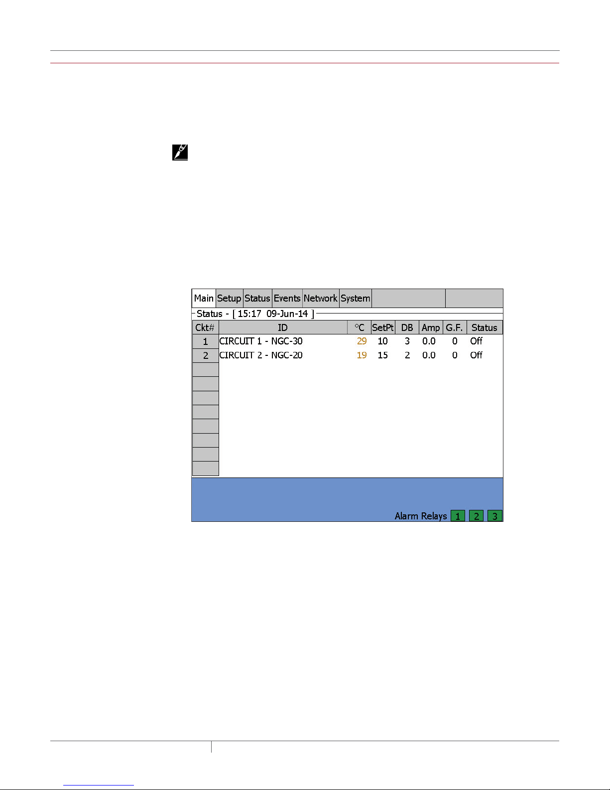
3.3.2 MAIN STATUS WINDOW
The main status window displays the status of all circuits that have been setup. For each circuit,
the main window displays:
Fig. 3.7 Main window with circuit status
Ckt# Circuit number
ID Identification tag for the Circuit
°C or °F The control temperature
SetPt Desired maintain temperature
DB Dead Band
Amps Heater current amperes
G.F. Heater ground-fault current
Status Relay (heater on, off or trip) and communication status
Color Coding of Main Window
The data in the °F/°C, Amps, and G.F. columns are displayed in color to identify their current state.
Green When heater is energized (status On), within Normal range of setup
parameters
Red In Alarm condition
Orange (°F/°C only) - Temperature not within setpoint + dead band range
Alarm Relay Status
Green No alarm
Red In Alarm condition
IMPORTANT: A Configuration Spreadsheet has been developed to assist in the collection of
specific circuit details. This spreadsheet is located in Appendix F.
industrial heat tracing solutions
EN-RaychemNGC30UIT2Programming-AR-H5818602/16
29 / 84
Page 30

3.3.3 SETUP | CIRCUIT WINDOW
The Setup | Circuit window is the first window of the Setup sequence.
Fig. 3.8 Setup | Circuit window
Circuit Entry Field
The Circuit # is assigned when setting up a Circuit in the Raychem NGC-30 program. It is the
primary reference for all windows. Once a Circuit is added, you cannot change its Circuit number;
however you can delete the Circuit (except for Circuit 1). This Setup|Circuit window is also where
you can select an existing Circuit.
Enabled/Disabled Toggle Button
When Enabled, the NGC-UIT2 monitors and generates Circuit alarms.
If a relay output has been assigned to the Circuit, the relay output turns on or off based upon
set-up parameters and RTD inputs, and the selected control mode.
When Disabled, the NGC-UIT2 has disabled the Circuit, and does NOT generate alarms or
control the relay assigned to the Circuit. The relay remains in the off position. The Circuit is
grayed out in the main window to show it is Disabled.
Delete Button
Deletes the Circuit that is currently being displayed and removes it from the main window. Any
Circuit can be deleted EXCEPT for Circuit 1. The program asks for confirmation before deleting.
ID Entry Field
The Circuit ID is user-definable name tag. The default is “ID XXX” (where XXX is the Circuit
number).
Limit: 40 characters (character strings are truncated on the Main Window after 16
characters but displayed in full on Status and Setup win-dows)
industrial heat tracing solutions
EN-RaychemNGC30UIT2Programming-AR-H5818602/16
30 / 84
Page 31
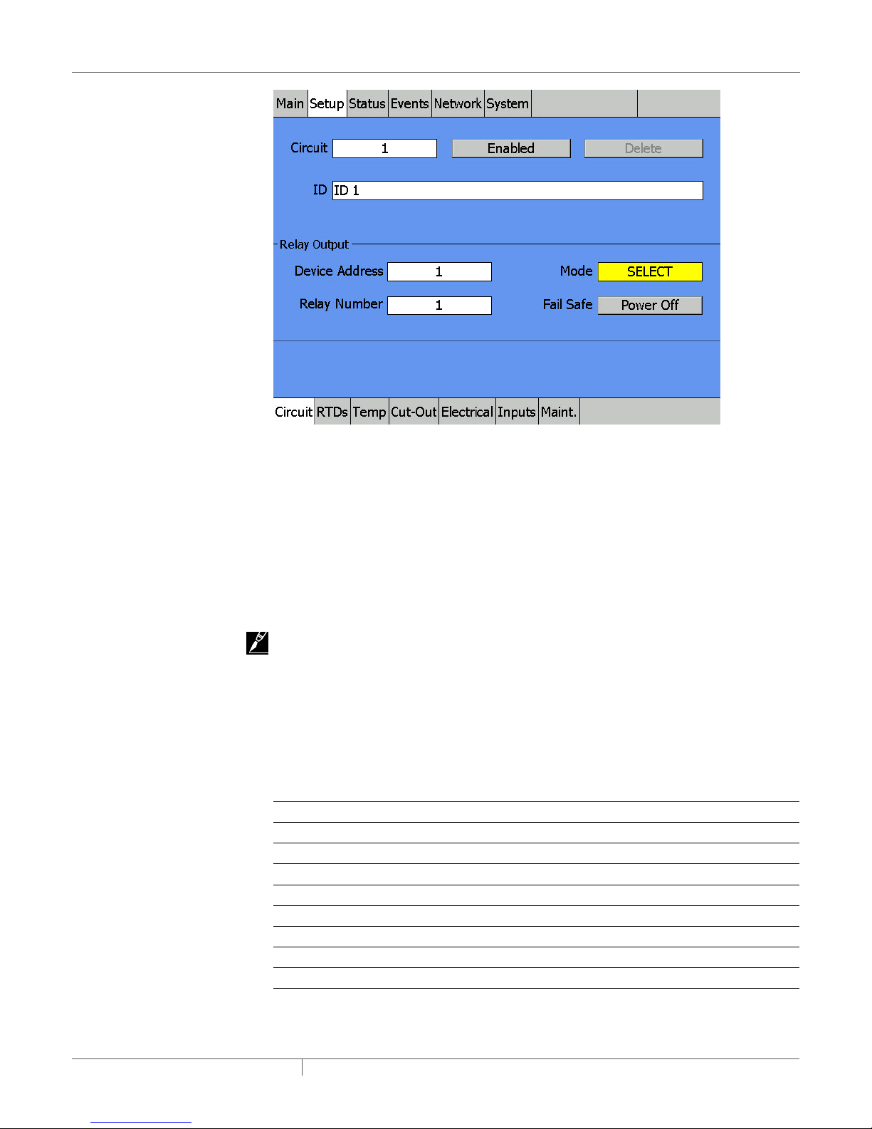
Fig. 3.9 Setup | Circuit window mode
Relay Output Section This section defines the device/relay and the operating mode assigned to the
Circuit.
Device Address Entry Field The device address is the number assigned to a NGC-30-CRM/-CRMS
board via the rotary selector switches. Each NGC-30-CRM/-CRMS must be assigned a unique
number (no other device can share a device address whether it’s a Relay Output device or RTD
input device). All device addresses are scanned on initial startup. If devices are added after initial
startup, the user must perform a system re-scan. (For more information on scanning for devices,
see section 3.3.24 Network | Devices Window on page 56.)
Device Address Range: 0–99 (For available device addresses and specific limits, see Table
3.5 Available Device Addresses on page 54.)
IMPORTANT: If no device address is entered (0), the Circuit is limited to temperature-monitoring
and temperature- alarming only.
Relay Number Entry Field The relay number defines which of the 5 control channels on the NGC30-CRM/-CRMS board controls the heater’s switching device. When the display shows dashes
(---) rather than an address, no switching device has been assigned to the Circuit. For NGC-20
controllers, the relay number will always be 1.
Mode Entry List The modes are the various control schemes that control a Circuit. There are four
different control modes associated with a NGC-30-CRM panel plus one voltage monitoring mode,
and five with a NGC-30-CRMS panel plus one voltage monitoring mode.
Table 3.1 Control Modes
Modes NGC-30-CRM NGC-30-CRMS* RMC NGC-20
On/Off X X X X
Proportional X
PASC X X X X
Always On X X X X
Always Off X X X X
Voltage X X X
Monitor Only X X
*Soft Start always active with CRMS (See Soft-Start Feature information below)
industrial heat tracing solutions
EN-RaychemNGC30UIT2Programming-AR-H5818602/16
31 / 84
Page 32

3.3.4 CONTROL MODES DEFINITIONS
On/Off
The NGC-UIT2 monitors the control temperature and compares it to the setpoint. If the control
temperature is above the setpoint by more than the Dead Band value (see page 35) the relay
output is turned off. If the control temperature falls below the setpoint temperature, the output is
turned on. The control temperature is defined as the lowest RTD temperature input value for that
Circuit.
Proportional
This algorithm monitors the control temperature of the Circuit and compares it to the setpoint
temperature. If the control temperature is at or below the setpoint temperature, then power is
applied to the heater with a duty cycle of 100%. If the control temperature is equal to or greater
than the control setpoint temperature +4°F, then the relay output will have a duty cycle of 0%. The
control temperature is constantly monitored, and the output duty cycle is adjusted proportionally
once per second. See Appendix A for additional information on Proportional Control.
Soft-Start Feature
This feature is a time-ramped soft start that reduces surge current produced by heaters at
startup. When a solid state output relay is first turned on, the duty cycle is ramped from 0 to 100%
in 2.5% (25 millisecond) increments over a 40 second period. The update rate for each step is fixed
at 1 second.
This automatic feature is included only when using SSRs as an output device. It is incorporated
into all control modes (On-Off, Proportional, PASC, Always On). If an output has been off for more
than 10 minutes, the soft-start algorithm will reset and be activated the next time the SSR turns
on. The soft-start algorithm will also reactivate whenever the NGC-30-CRMS boards loses power
or is reset.
PASC (Proportional Ambient Sensing Control)
PASC takes advantage of the fact that the heat loss from a pipe is proportional to the temperature
difference between the pipe and the ambient air. This is true regardless of heater type, insulation
type, or pipe size. Once the heat tracing and insulation on a pipe has been designed to balance
heat input with heat loss and maintain a particular temperature, the main variable in controlling
the pipe temperature becomes the ambient air temperature.
The NGC-30-CRM/-CRMS has a control algorithm that uses the measured ambient temperature,
desired maintain temperature, minimum ambient temperature assumption used during design,
and size of the smallest pipe diameter to calculate how long the heater should be on or off to
maintain a near-constant pipe temperature.
Always On
The relay output is switched on (user override), turns on the power to the heater and leaves it on.
IMPORTANT: Monitor the pipe temperatures to avoid overheating. Alarms are still active.
Always OFF
The relay output is switched off (user override), turns off the power to the heater, and leaves it off.
IMPORTANT: Monitor the pipe temperatures for low temperature alarms. Alarms are still active.
Voltage
Voltage mode allows the NGC-UIT2 to monitor line voltage from the NGC-30-CRM/-CRMS boards.
The NGC-30-CRM/-CRMS must have an NGC-30-CVM connected to the line current sensor input
when selecting voltage mode. As a result, this channel of the NGC-30-CRM/-CRMS cannot be
used to control an output device. But an RTD can be connected to this channel’s input to set up an
additional temperature monitoring Circuit. For an NGC-20 controller, the voltage mode is not an
option since this is a standard feature.
Monitor Only
This is the default mode that allows temperature monitoring for the Circuit. This means no output
device has been selected.
industrial heat tracing solutions
EN-RaychemNGC30UIT2Programming-AR-H5818602/16
32 / 84
Page 33

Fail Safe toggle button
The Fail Safe control button turns the power on or off to the heater if the Circuit loses all valid RTDs.
When the last remaining sensor for control fails (or communication with the sensor is lost), the
NGC-UIT2:
• Signals an alarm for the failure of the sensor
• Changes control of the circuit to the fail safe control selected
• Changes the control status display to indicate that control of the circuit is in the fail safe state
• Records the events
When the sensor for control is returned to service, the controller signals the alarm has been
cleared, returns the Circuit to its normal control mode, and records both of these events.
IMPORTANT: Default is OFF
3.3.5 SETUP | RTDS WINDOW
In order to assign an RTD to a Circuit, it must be shown in the Network|Devices table.
By default, each NGC-20 controller and each channel of the NGC-30-CRM/-CRMS has an
associated RTD input.
The NGC-30 program first checks to see if the default RTD is available. On any NGC-30-CRM/-
CRMS (5GF-C) board, the first RTD input is automatically coupled with the first relay output; the
second RTD is linked with the second output relay, etc. When a control layout is chosen with an
RMC and RMM2 then, by default, no RTD will be associated with the RMC output channel. The
users decide themselves which temperature input is linked to which output channel.
Fig. 3.11 indicates an RTD connected to the RTD 1 terminal block, so the RTD set-up screen
indicates the default assignment is already completed. This selection is grayed out because you
cannot alter this default selection. In the event of a communications failure or UIT2 failure, the
circuit reverts to this default RTD for control purposes.
Fig. 3.10 Setup | RTDs window - Default RTD, hard-wired to CRM/-CRMS board
In general, up to three additional RTDs can be associated with this Circuit. When the system is
fully functional, the lowest RTD value from the list of four will be used for control temperature. If
no RTD is connected to the input terminals for this Circuit, then all four lines can be used to assign
RTDs from elsewhere in the system. However, in the event of a communications or UIT2 failure, no
industrial heat tracing solutions
EN-RaychemNGC30UIT2Programming-AR-H5818602/16
33 / 84
Page 34

RTD input is available and the relay output for this Circuit goes to the failsafe mode established in
the Setup|Circuit window.
Fig. 3.11 Setup | RTDs window- Four RTDs are assigned to the circuit
Each RTD can be set to operate in two modes: Control or Monitoring. If an SES is used as a
Continuity sensor, a third option for Continuity is also selectable. If an RTD is set to Control, the
output of the Circuit will be based on this RTD in conjunction with any other Control RTDs in Auto
On/Off mode. These RTDs will also trigger temperature alarms and cutouts. However, if an RTD is
set to Monitoring, its temperatures will not be used to control the circuit's relay output. RTDs set
to Monitor will trigger temperature alarms but not high temp cutout. A RTD mode set to Continuity
will only report that power has reached the SES module.
The table below indicates the RTD Mode (RTD application) options for each RTD device.
Table 3.2 RTD Mode Options
Connection Type RS-485 Device RTD Device RTD Modes
Control Monitor Continuity
Hard-wired, local CRM/CRMS the
Direct X -- --
same circuit
Hard-wired, not
local
CRM/CRMS
another circuit
Direct X X --
Hard-wired, local NGC-20 Direct X -- --
Serial RMM2 Direct X X --
Serial PLI-SES/SPC via SES-RTD X X --
Serial PLI-SES/SPC No RTD -- -- X
Serial PLI-SES/SPC via SES-SPC X X --
Serial PLI-TT via 700-TT X X --
IMPORTANT: The SES-CONT device does not have any RTDs, thus can not control or monitor the
temperature. Therefore, the only RTD Mode that can be selected is Continuity. In Continuity Mode,
the integrity of the heat-tracing system is monitored.
industrial heat tracing solutions
EN-RaychemNGC30UIT2Programming-AR-H5818602/16
34 / 84
Page 35

3.3.6 SETUP | TEMP WINDOW
This window contains all temperature parameters for control and monitoring of Circuits.
Fig. 3.12 Setup | Temp window
Setpoint Entry Field Use with On/Off, Proportional, and PASC control modes. The Setpoint is the
desired maintain temperature for the circuit.
Based on the measured control temperature, the Raychem NGC-20 and NGC-30 switches the
relay output to maintain the system at the desired set point.
Range NGC-20: –80°C (–112 °F) to 700°C (1292 °F)
Default: 10°C (50°F)
Range NGC-30: –73°C (–99°F) to 482°C (900°F)
Default: 10°C (50°F)
Dead Band Entry Field Use with On/Off Control.
If the control temperature is above the Setpoint temperature plus Dead Band, the relay output is
turned off. If the control temperature is below the Setpoint temperature, the output is turned on.
Range NGC-30: 1°C (1°F) to 50°C (50°F)
Default: 3°C (5°F)
High Temp Alarm Entry Field Use with all modes.
If any RTDs assigned to a Circuit measures a temperature above this threshold, the NGC-UIT2
generates an alarm.
Range NGC-20: –80°C (–112°F) to 700°C (1292°F)
Default: 10°C (50°F)
Range NGC-30: –73°C (–99°F) to 482°C (900°F)
Default: 149°C (300°F)
Low Temp Alarm Entry Field Use with all modes.
If any RTDs assigned to a Circuit measures a temperature below this threshold, the NGC-UIT2
generates an alarm.
Range NGC-20: –80°C (–112°F) to 700 °C (1292°F)
Default: 10°C (50°F)
Range NGC-30: –73°C (–99°F) to 482°C (900°F)
Default: –12°C (–10°F)
industrial heat tracing solutions
EN-RaychemNGC30UIT2Programming-AR-H5818602/16
35 / 84
Page 36

Temperature Alarm Filter Entry List
This minimizes nuisance alarms by forcing the NGC-UIT2 to verify that the alarm condition
continually exists over the selected period of time before alarming.
Range: 10 to 59,940 seconds
Default: 900 seconds (15 minutes)
IMPORTANT: The 15 second option is for testing and demostration purposes. Choosing this option
for normal use may cause nuisance alarming since this option may not allow the NGC-UIT2 time
to verify that the alarm conditions exist.
3.3.7 SETUP | Limit Cut-Out window
Fig. 3.13 Setup | Limit Cut-Out window
High Limit Cut-Out Entry Field
High Limit Cut-Out feature is triggered depending on Control and RTD Modes. The Table below
indicates which RTD Modes will initiate a High Limit Cut-Out for each Control Mode. If these RTDs
are assigned to a Circuit and measure a temperature above the High Limit Cut-Out threshold, the
NGC-UIT2 generates an alarm and the relay output is turned off. If he High Limit temperature is
below this threshold minus the Deadband, the output is turned on.
Table 3.3 Control Modes and RTD Modes That Trigger High Limit Cut-Out
Control Modes RTD Modes
Control Monitor Continuity
On/Off X -- --
Proportional X -- --
PASC -- X --
Always On X -- --
Always Off -- -- --
industrial heat tracing solutions
EN-RaychemNGC30UIT2Programming-AR-H5818602/16
36 / 84
Page 37

These are the general settings for the Raychem NGC-30:
Range: –73°C (–99°F) to 482°C (900°F)
Default: 482°C (900°F)
For Raychem NGC-20:
Range: –80°C (–112°F) to 700°C (1292°F)
Default: 700°C (1292°F)
Low Limit Cut-Out Entry Field - NGC-20 Only
Low Limit Cut-Out feature is triggered depending on Control and RTD Modes of the NGC-20. Table
3.3 indicates which RTD Modes will initiate a Low Limit Cut-Out for each Control Mode. If these
RTDs are assigned to a Circuit and measure a temperature above the Low Limit Cut-Out threshold,
the NGC-UIT2 generates an alarm and the relay output is turned off. If the Low Limit temperature
is above this threshold plus the variable Deadband, the output is turned on.
Limit Cut-Out Enable/Disable Toggle Buttons
Enables or disables the high limit cut-out capability. When enabled, the NGC-UIT2 alarms and the
output relay turns OFF if any RTDs exceed the cut-out value. If the high limit cut-out is disabled,
the relay output will continue to function normally without the high temperature cut-out feature.
3.3.8 SETUP | ELECTRICAL WINDOW
This window configures ground fault alarm and trip values for the Circuit. (This feature is only
supported when used with CRM/CRMS or Raychem NGC-20 controller boards. This feature is not
supported with RMC controller output modules. Ground fault alarm is a latching alarm and must
be reset.) These alarms are latching alarms and must be reset.
Fig. 3.14 Setup | Electrical window
Ground-Fault Alarm Entry Field
Set the Ground-Fault Alarm threshold to the desired level. The ground-fault alarm may not be
disabled.
Range Raychem NGC-20: 10 mA to 250 mA
Range Raychem NGC-30: 10 mA to 200 mA
Default: 20 mA
industrial heat tracing solutions
EN-RaychemNGC30UIT2Programming-AR-H5818602/16
37 / 84
Page 38

Ground-Fault Trip Entry Field
Set the Ground-Fault Trip value to the desired level. If a Ground-Fault Trip condition occurs, the
relay output is turned off and will not turn on until the fault has been cleared, and the Circuit is
reset in Status | Circuit window.
Range Raychem NGC-20: 10 mA to 250 mA
Range Raychem NGC-30: 10 mA to 200 mA
Default: 30 mA
Ground-Fault Trip Toggle Button
Enables or disables the ground-fault trip capability. When enabled, the output relay turns OFF if
the ground-fault current exceeds the trip value. An alarm is created in the Events window. The
output relay is not functional until the ground-fault problem is fixed and the alarm is reset. If
the Ground-Fault Trip is disabled, the relay output will continue to function normally but without
ground-fault safeguards.
WARNING:
Fire Hazard. A ground-fault alarm means the heating cable has been damaged or improperly
installed and must not be ignored. Disabling the ground-fault trip function reduces safety and
could result in sustained electrical arcing or fire. To minimize the risk of fire if the alarm activates,
shut off the power and repair the system immediately.
Low Current Alarm Entry Field
If the relay output currents fall below Low Current Alarm, the NGC-UIT2 will alarm.
Range Raychem NGC-20: 0-30 A, where 0 = Alarm Disabled
Default Raychem NGC-20: 30 A
Range Raychem NGC-30: 0-100 A, where 0 = Alarm Disabled
Default: 30.0A
High Current Alarm Entry Field
If the relay output current is above the High Current Alarm, the NGC-UIT2 alarms and stays in
alarm until the high current is cleared, and the alarm is reset in the Status | Circuit window.
Range Raychem NGC-20: 0-30 A, where 0 = Alarm Disabled
Default Raychem NGC-20: 1.0 A
Range Raychem NGC-30: 0–100 A, where 0 = Alarm Disabled
Default: 5.0 A
Power Limit Entry Field Use with SSR (NGC-30-CRMS) only
This feature limits the average power available at the output, by allowing the user to set a
maximum duty cycle for the Circuit.
IMPORTANT: The heater is switched on and off over a time base of several seconds. For example,
an 80% power output is achieved by switching the heater on at 100% for 800 milliseconds and then
off for 200 milliseconds. Instantaneous power consumption is not limited when the heater is on.
Range: 10–100%
Default: 100%
High Voltage Alarm Entry Screen
If the voltage monitoring module measures line voltage above this threshold, the NGC-UIT2
generates an alarm.
Range: 50 – 305 V
Default: 270 V
Low Voltage Alarm Entry Screen
If the voltage monitoring module measures line voltage below this threshold, the NGC-UIT2
generates an alarm.
Range: 50 – 305 V
Default: 90 V
industrial heat tracing solutions
EN-RaychemNGC30UIT2Programming-AR-H5818602/16
38 / 84
Page 39

3.3.9 SETUP | PASC WINDOW
This window configures the PASC setup if the PASC control mode is selected for a Circuit.
Fig. 3.15 Setup | PASC window
Min Ambient Temp Entry Field
The Min Ambient Temp is the “lowest ambient temperature” that was used when the heat-tracing
system was designed. The entered value should agree with the value used by the design
engineer to ensure that the heating-tracing system was sized correctly.
Range Raychem NGC-20: –73°C (–99°F) to 51°C (124°F)
Range Raychem NGC-30: –73°C (–99°F) to 51°C (125°F)
Default: –40°C (–40°F)
Min Pipe Size Entry List
Min. Pipe Size is the diameter of the smallest heat-traced pipe in the group controlled by this
Circuit. Small diameter pipes heat up and cool down more rapidly than larger diameter pipe.
Therefore, the PASC duty cycle is calculated over a shorter time base. Larger diameter pipes heat
and cool less rapidly, so the on/off periods for the heater system can be stretched over a longer
period. If electromechanical contactors are being used to control the heater circuit, the longer
time base reduces the number of contactor on/off cycles and extends the contactor life.
List: 0.5, 1, >= 2 inches
Default: 0.5 inches
Power Adjust Entry Field
This allows the PASC control to be adjusted when the heating cable output is greater than the
design assumption, or if the pipe insulation proves to be more efficient than assumed. Pipe
temperature may run higher or lower than desired if the heating cable has a different output than
required to offset the heat loss. The Power Adjust parameter enables a reduction or an increase in
the heat-tracing effective power by entering a value less or greater than 100%
IMPORTANT: If improperly used, the Power Adjust parameter can cause the piping to get too
cold or too hot. If unsure, leave at 100%. Do not change this value unless an engineer calculates
the temperature impact on the system and determines that it is safe to do so. Be particularly
cautious if the circuit has more than one diameter of pipe or type of heat tracing. Contact a Pentair
Industrial Heat Tracing Solutions representative for assistance with this factor.
Range: 10–200%
Default: 100%
industrial heat tracing solutions
EN-RaychemNGC30UIT2Programming-AR-H5818602/16
39 / 84
Page 40

3.3.10 SETUP | PLI WINDOW
This window allows you to set the update time when using an PLI. The update time, in minutes,
is used as the time that is waited before polling the sensor(s) for a new temperature on a circuit
after the circuit has turned off. The sensors are continuously polled while the circuit is on.
Fig. 3.16 Setup | PLI window
Heater On - When the heating cable is ON, the temperature measurements will be transmitted
from the SES and SPC transmitters to the PLI module/NGC-30 controller approximately every 5 to
11 minutes depending on the SES address. When using 700-TT transmitters, the temperature data
will be polled periodically. The time interval is within minutes and depends on the number of 700TT transmitters and the number of connected circuits.
Heater OFF - When the heating cable is OFF, the temperature measurements will be transmitted
from the SES, SPC and 700-TT transmitters to the PLI module/NGC-30 controller based on the
configured PLI Update Interval time. The NGC-30 system turns the heater on in the time intervals
defined in the field PLI Update Interval and reads the temperature measurements. Based on these
temperature measurements and the Setpoint, NGC-30 Control System determines whether to
leave the heater On or turn it Off.
If the Update Interval time is set to 10 minutes, the NGC-30 control system turns ON the heater
every 10 minutes.
On time intervals when no additional heat is required is as follows:
• For 700-TT Transmitter ….. 5 seconds
• For SES Transmitter ……..Highest SES Address Number for that circuit / 2 + 5 = in seconds
Range: 1-255 Minutes
Default: 10 Minutes
industrial heat tracing solutions
EN-RaychemNGC30UIT2Programming-AR-H5818602/16
40 / 84
Page 41

3.3.11 SETUP | MAINT. WINDOW
This window configures the maintenance schedule.
Fig. 3.17 Setup | Maint. window
Power Cycle Start Time Entry Field
After entering a start time, the Power Cycle test feature turns on the heat tracing for a one-minute
period each day starting at the indicated time. If the heater system is damaged during a season
when the system would normally be turned off, the daily Power Cycle test can help detect the
problem within 24 hours. This is particularly helpful in warm months when heat tracing may not
be energized.
Range: Any time selected from the 24-hour clock (00:00–23:59, where 00:00 is off)
Power Cycle Test Interval Entry Field
The default interval is 24 hours. The example in the window above schedules a one-minute test
every morning at 6:00 a.m. Other entries are possible, but multiples of 24 hours are recommended
to preserve the predictable start-time. For instance, 48 hours will run the test at 6:00 a.m. every
other day. 168 hours will run the test once a week starting with the first occurrence of 8:01 a.m. after
the set-up procedure and once a week thereafter. To run the test twice a day, enter 12 hours etc.
Range: 1–1000 hours
Default: 24 hours
Heater Time Alarm Entry Field
This entry is used to create a heater inspection maintenance schedule. Enter the number of
hours the heater can be energized before inspection and testing is due. The NGC-UIT2 tracks the
accumulated “on” time for each heater circuit and generates an alarm message and advises that
heater maintenance is due.
Range: 1–1,000,000
Default: 100,000
Relay Cycle Alarm Entry Field (For EMR type devices only)
This entry is used to create a contactor inspection maintenance schedule. Enter the number of
times that contactors can be cycled on/off before inspection and testing is desired. The NGC-UIT2
tracks the accumulated number of on/off switches for each contactor and generates an alarm
message to advise that contactor maintenance is due.
Range: 1–2,000,000
Default: 500,000
industrial heat tracing solutions
EN-RaychemNGC30UIT2Programming-AR-H5818602/16
41 / 84
Page 42

3.3.12 SETUP | INPUTS
This window configures the Digital Inputs (if available) for a Circuit.
Fig. 3.18 SETUP|INPUTS window
Power Input
This window is initially displayed with the empty boxes for Device Address and Input Number.
If an “Auxiliary Contact” is available for the Circuit output device (an optional set of contacts on
a mechanical contactor or from an auxiliary relay in parallel with the heater circuit) then this
window allows those contacts to be associated with the circuit for power monitoring purposes. If
the NGC-UIT has attempted to turn a contactor ON, and the contactor fails to energize the circuit,
then this digital input can be used to detect the abnormal situation. Selecting Device Address and
Input Number provide numerical input windows and lists of available input locations. There is not
default association of Input Number so Circuit 1 can be monitored from a set of relay contacts
connected to DI 53-1 as in this example.
Circuit Breaker Trip Input
This window is initially displayed with the empty boxes for Device Address and Input Number. If the
Branch Circuit Breaker for this Circuit is equipped with “bell alarm contacts” that change state
when the circuit breaker has tripped, then those contacts can be monitored by the NGC-UIT. If the
branch circuit breaker trips for high current or high ground fault, then the abnormal condition
will be detected by the UIT and displayed as an alarm condition. Selecting Device Address and
Input Number provide numerical input windows and lists of available input locations. There is
not default association of Input Number so circuit breaker providing power to Circuit 1 can be
monitored by connecting its bell alarm contacts to DI 50-2 as in this example.
Trip State (Toggle)
Pushing this button allows the user to define the relay condition that signals the alarm condition.
User Alarm
This window is initially displayed with the empty boxes for Device Address and Input Number. The
Alarm text will show “User Alarm”. The user can link a digital input to this user alarm. The user
can define per circuit a user definable alarm text. In case the Digital Input goes into alarm state
(“Open” or “closed” depending upon the Alarm State selection) the alarm text will appear in the
alarm summary.
industrial heat tracing solutions
EN-RaychemNGC30UIT2Programming-AR-H5818602/16
42 / 84
Page 43

3.3.13 SETUP | SAFETY LIMITER WINDOW (Raychem NGC-20 ONLY)
This window configures the Safety Limiter (if available) temperature.
Fig. 3.19 SETUP|SAFETY LIMITER window
Actual Safety Limiter Setpoint Status Field
The Safety Limiter temperature setpoint that the Raychem NGC-20 is currently configured.
New Safety Limiter Setpoint Entry Field
Set the New Safety Limiter Setpoint to the desired value. If the Limiter’s RTD temperature exceeds
this value, the relay output is turned off and will not turn on until the Limiter’s RTD temperature is
below this setpoint and the alarm is cleared.
Range: –60°C (–76°F) to 599°C (1110°F)
Default: 300°C (572°F)
Safety Limiter Setpoint Timeout Entry Field
For the Raychem NGC-20 to accept the New Safety Limiter Setpoint, the black limiter button
on the display board must be pressed and held down until the new value is successfully sent. A
message will pop up stating “Safety Limiter Setpoint has been updated successfully”. The Safety
Limiter Timeout entry is the amount of time that the UIT will allow the user to complete the above.
Range: 1 second to 3600 seconds
Default: 60 seconds
Send Action Button
Initiates the process of updating the Safety Limiter Setpoint. When pressed, a countdown timer
will display, counting down the time remaining to complete the New Safety Limiter Setpoint
process.
Trip Safety Limiter Action Button
When pressed, this will manually force the Safety Limiter to trip.
industrial heat tracing solutions
EN-RaychemNGC30UIT2Programming-AR-H5818602/16
43 / 84
Page 44

3.3.14 SETUP | LOAD SHED WINDOW (Raychem NGC-20 ONLY)
This window enables or disables the various load shed zones. The actual configuration and
implementation of these zones are done in Raychem Supervisor.
Fig. 3.20 SETUP|LOAD SHED window
Each independent Raychem NGC-20 controller can be assigned to none, some or all of the 16
independent zones. Those zones that have been assigned to the Raychem NGC-20 controller
requires the Enable box to be checked for the Load Shedding process to activate.
If the Failsafe box is checked, the Raychem NGC-20 controller will revert to the failsafe mode
configured in the Setup|Circuit window if the Raychem NGC-20 controller loses communication
with Raychem Supervisor.
3.3.15 STATUS | CIRCUIT WINDOW
The status Circuit window displays the status information for individual Circuits. Data in the status
menus cannot be changed; it is informational only.
industrial heat tracing solutions
EN-RaychemNGC30UIT2Programming-AR-H5818602/16
44 / 84
Page 45

Fig. 3.21 Status | Circuit window
The data in the Control Temp, G.F. and Current windows are displayed in color to identify their state:
• Black - Circuit is off
• Green - Within Normal range of setup parameters
• Red - In alarm condition
• Orange - Control Temp only. Temperature not within setpoint + Dead Band range
• Blinking Red/Orange - Alarm Reset button only. A latching alarm event has occurred
The fields and displays in the Status|Circuit provide the following information:
• Circuit Entry Field - Enter the Circuit number to view the status of a specific Circuit.
• Alarm Reset Action Button - In normal state, the Alarm Reset button is grayed out. If a latching
alarm occurs, the Alarm Reset blinks orange/red. The alarm cannot be reset until the fault has
been cleared.
• ID Field
- Displays the ID tag defined in Setup/Circuit window.
• Control Temp Field
- The Control Temp is the temperature the NGC-UIT2 is using for the control algorithm. If
more than one RTD is connected to a Circuit, the system displays the lowest Control Temp of
all the RTDs assigned to that Circuit.
• Setpoint
The Setpoint is the desired maintain temperature for the circuit.
• G.F. Field
- Displays the ground-fault current for the Circuit.
• Relay Field - Displays the Relay device and number defined in the Setup/Circuit window.
• Status Field - Displays the relay output status (on, off, or trip) of the EMR or SSR. If
communication is lost to the output device, a red COMM appears and alarms.
• Mode Field
- Displays the Control Mode selected in Setup | Circuit window.
• Current Field
- Displays the heater amperage of the Circuit when the relay output is on.
• CB Trip State
Give the input status of the CB signal. In case of a circuit breaker trip it will display in RED the
text "Tripped".
industrial heat tracing solutions
EN-RaychemNGC30UIT2Programming-AR-H5818602/16
45 / 84
Page 46

3.3.16 STATUS | RTDS WINDOW
The Status|RTDs window lists the RTD devices and numbers assigned to the selected Circuit,
along with the last reported temperature from each RTD and the assigned RTD Mode.
Data in this status window cannot be changed.
Fig. 3.22 Status |RTDs window
3.3.17 STATUS | PASC WINDOW
The Status | PASC window displays the current status of Circuit switching PASC algorithm. Data
displayed in this status window cannot be changed.
Fig. 3.23 Status | PASC window
The Status|PASC window provides the following controls:
• On Count Field - The duration (in seconds) an EMR or SSR is on during one on/off cycle.
• Off Count Field - The duration (in seconds) an EMR or SSR is off during one on/off cycle.
industrial heat tracing solutions
EN-RaychemNGC30UIT2Programming-AR-H5818602/16
46 / 84
Page 47

• Next Relay Switch Field -The time (in seconds) until the EMR or SSR changes state. This value
counts down to zero for each on or off cycle.
• Relay State Field - Current state (off or on) of the EMR or SSR assigned to this Circuit.
3.3.18 STATUS | VOLTAGE WINDOW
The Status | Voltage window displays the measured line voltage from the NGC-30-CRM/CRMS.
Fig. 3.24 Status | Voltage window
3.3.19 STATUS | PLI WINDOW
This window displays information regarding the update times for a PLI system when the heater is
off for the selected circuit.
Fig. 3.25 Status | PLI Window
industrial heat tracing solutions
EN-RaychemNGC30UIT2Programming-AR-H5818602/16
47 / 84
Page 48

The Next PLI Update displays the number of seconds until the next poll.
When the timer reaches zero, the UIT2 will turn the circuit on for a specified amount of time based
on the sensor address and update the temperature. At this point, the circuit will either remain on
or turn off again based on the new temperature.
Relay state field shows the current relay state.
IMPORTANT: The timer will stay at zero while it's updating. If the circuit is on because the
temperature is below the setpoint, the timer will remain at zero until the circuit turns off.
IMPORTANT: The value on the screen may not update every second while on this window.
3.3.19.1 PLI TEST UTILITY
The PLI Test utility allows you to test the communication between the UIT2 and the PLI module.
You can use this to test and diagnose any issues you may be having receiving temperatures from
the SES/SPC and TT temperature sensors.
IMPORTANT: This utility only tests communications between the UIT2 and the PLI module. The
purpose of this test is to force the SES/SPC/TT temperature sensors to report temperatures to the
PLI in a timely manner. The UIT2 does not directly communicate to the temperature sensors
The PLI Test utility can be launched from the Status|PLI screen. The circuit that is being viewed
must have a PLI RTD assigned to it for this screen to appear. Tapping on the Start PLI Cycle Test
button on this screen will launch the tester.
Fig. 3.26 The PLI test utility (Shown using PLI-TT)
In the PLI test utility, all of the PLI RTDs assigned to the current circuit will be displayed on this
screen. The temperatures will appear as the values are being read during the test process. Along
with the temperature, the last update will appear to the right. This timestamp shows the time
when the last communication occurred between the UIT2 and the PLI module.
Below the temperatures is the Start button which will initiate the test. After the test has started,
pressing this button again will stop the test.
Below the button is an input box for the number of test cycles the utility will perform. You can
change this to what is required for your specific test.
industrial heat tracing solutions
EN-RaychemNGC30UIT2Programming-AR-H5818602/16
48 / 84
Page 49

3.3.19.2 UNSWITCHED CIRCUITS
Fig. 3.27 An unswitched PLI-TT circuit test in progress
Using this utility on an unswitched circuit will configure the UIT2 to continuously poll the PLI
approximately every second. With a theoretical maximum time of 11 minutes between SES/SPC
transmission times, 660 test cycles should result in SES/SPC temperatures being reported if there
are no errors or issues with communication.
TT sensors, on the other hand, will each sequentially report their temperatures to the PLI.
Therefore, TTs should always report a temperature for each test cycle.
3.3.19.3 SWITCHED CIRCUITS
Fig. 3.28 A PLI-SES switched circuit test in progress
If the tester utility is used on a switched circuit, the UIT2 will force the controlling relay on to
power the sensors.
If the circuit is using SES/SPC sensors and is already on, the UIT2 will switch the circuit off and
then immediately back on to force the SES/SPC sensors to report their temperatures. This will
occur every test cycle. The time required for each cycle will depend on the SES/SPC address
numbers on the circuit since each sensor will report their temperatures at a specific time after
power up based on its address. A countdown timer will be displayed to indicate when the next test
cycle will occur.
If TT sensors are being used, temperatures will be updated on the UIT2 every second after the
circuit is forced on.
industrial heat tracing solutions
EN-RaychemNGC30UIT2Programming-AR-H5818602/16
49 / 84
Page 50

3.3.20 STATUS | SAFETY LIMITER WINDOW (Raychem NGC-20 ONLY)
The Status|Safety Limiter window displays the current Safety Limiter’s temperature and a
historical record of minimum and maximum values recorded since the last Reset time. Data in this
status window is “read only” information. Pressing reset releases all min./max. values and starts
another period of accumulation for minimum and maximum values.
Fig. 3.29 Status|Safety Limiter window
The Status|Safety Limiter window provides the following controls:
• Safety Limiter Temp Field - Displays the last reported temperature from the Safety Limiter’s RTD
• Safety Limiter Setpoint Field - The temperature that the Raychem NGC-20 is using for the
Safety Limiter alarm
• Reset Safety Limiter Action Button - In normal state, the Reset Safety Limiter button in
grayed out. If a latching alarm occurs, the Reset Safety Limiter button blinks orange/red.
The alarm cannot be reset until the Safety Limiter’s temperature is below the Safety Limiter’s
Setpoint.
• Safety Limiter Min Temp - The lowest temperature reported by the Safety Limiter’s RTD
since the last reset time
• Safety Limiter Max Temp - The highest temperature reported by the Safety Limiter’s RTD
since the last reset time
industrial heat tracing solutions
EN-RaychemNGC30UIT2Programming-AR-H5818602/16
50 / 84
Page 51

3.3.21 STATUS | MIN / MAX WINDOW
This window displays an historical record of minimum and maximum values recorded since the
last Reset time. Data in this status window is “read-only” information. Pressing reset releases all
values and starts another period of accumulation for minimum or maximum values.
Fig. 3.31 Status |Min/Max window
The Status|Min/Max window provides the following controls:
• Min Control Temp Field - The lowest measured temperature used for control reported by any
RTD associated with the Circuit since the last Reset time.
• Max Control Temp Field - The highest monitored temperature used for control reported by any
RTD associated with the Circuit since the last Reset time.
• Min Monitor Temp Field - The lowest temperature measured used for monitoring purposes
reported by any RTD associated with the Circuit since the last Reset time.
• Max Monitor Temp Field - The highest temperature measured used for monitoring purposes
reported by any RTD associated with the Circuit since the last Reset time.
• Max Voltage Field - The highest voltage recorded for the circuit since last Reset.
• Min Voltage Field -The lowest voltage recorded for the circuit since last Reset.
• Max GF Current Field - The highest ground-fault value recorded for the Circuit since the last
Reset time.
• Reset Button -Immediately resets all Min/Max values and begins updating Min./Max. fields with
new values.
• Max Current Field - The highest current recorded for the Circuit since the last Reset.
industrial heat tracing solutions
EN-RaychemNGC30UIT2Programming-AR-H5818602/16
51 / 84
Page 52

3.3.22 STATUS | MAINT. WINDOW
This window displays the cumulative time in hours the heater has been On and the number of
cycles the EMR has turned on and off for the selected Circuit. Data displayed in the counter
windows is read only. Pressing the Reset buttons resets the appropriate counter.
Fig. 3.32 Status | Maint. window
The Status|Maint. window provides the following controls:
• Heater Time On Field - Total time the heater has been energized since it was last Reset.
• Reset Heater Time Action Button - Resets heater time to 0, and begins updating the field with
new values.
• Relay Cycle Count Field - Total number of times the EMR has switched on since it was last Reset.
• Reset Relay Cycle Count Action Button - Resets the Relay Cycle count to 0, and cycle counts
begin again.
3.3.23 EVENTS WINDOW
The Events window displays a chronological history of all events and alarms. It retains the most
recent 2000 entries; after 2000 entries are recorded, the oldest entries are discarded as new
entries are added.
industrial heat tracing solutions
EN-RaychemNGC30UIT2Programming-AR-H5818602/16
52 / 84
Page 53

Fig. 3.33 Events window
The Events status listing window provides the following information:
• Time Toggle Button - By pressing the Time column heading, the display of times of the events
or alarms changes to descending or ascending order based on time of occurrence.
• Circuit Toggle Button - By pressing the Circuit heading, the display of events or alarms is
sorted by the Circuit number. Circuits are first displayed in ascending order. Pressing the
Circuit again toggles between ascending or descending order.
• Events, Press for Alarms Toggle Button
- By pressing the Events, Press for Alarms heading, the Events display filters events or
alarms by type. Time and Circuit column headings can then be used to further sort the
selected events or alarms for display. (IMPORTANT: The program automatically skips an
alarm type if no alarms of that type exist).
Table 3.4 Alarm Type Headings and Descriptions
Alarm Type/Headings Description
Any Alarm
Comm Alarm NGC-UIT2 display lost communication with an NGC-30-CRM/-
CRMS, PLI module, and/or RMM2 module(s)
Fail Safe Alarm Control mode of Circuit has been switched to Fail Safe control
mode
CB Trip Alarm Circuit Breaker Trip Alarm occurs when the Digital Input matches
the Circuit Breaker Trip state
Ground-Fault Alarm Heater’s ground-fault current went above high ground-fault current
alarm setting
Ground-Fault Trip Heater’s ground-fault current went above the ground-fault trip setting
Heater Time Alarm Heater’s energized time went above the heater’s alarm threshold
High Current Heater’s current went above high current alarm setting
High Temp RTD temperature went above high temp alarm setting
High Temp Cut-Out RTD temperature went above high temp cut-out alarm setting
High Voltage Line voltage went above high voltage alarm setting
Low Current Heater’s current went below low current alarm setting
Low Temp RTD temperature went below low temp alarm setting
industrial heat tracing solutions
EN-RaychemNGC30UIT2Programming-AR-H5818602/16
53 / 84
Page 54

Low Voltage Line voltage went below low voltage alarm setting
Power Input Alarm Power Input state does not match the Relay Output State
Relay Cycle Alarm EMR cycle count went above relay cycle alarm setting
Relay Failure Alarm EMR or SSR was commanded to turn off. However, a heater
current was still being detected. This condition can indicate a failed
contactor or SSR (stuck on)
RTD Failure Open or shorted RTD detected
User Alarm User configurable alarm
Safety Limiter Comm
Alarm
Safety Limiter Sensor
Raychem NGC-20 Safety Limiter sub-system cannot communicate
with Raychem NGC-20 processor
Raychem NGC-20 Safety Limiter RTD fails
Failure
Safety Limiter Trip Alarm Raychem NGC-20 Safety Limiter temperature above Safety Limiter
setpoint
Table 3.5 Events and Descriptions
Event Description
Alarm Ack Date and time stamps when an Alarm was acknowledged
CB Trip OK Circuit Breaker is no longer tripped.
Comm Alarm Communication with a specified Raychem device has been
interrupted
Comm OK Communication with device/s was restored.
Date/Time Error Date or time information is not correct and must be updated
Events Cleared Date and time stamps when Events menu was cleared in
System | Maint. window
Fail Safe Alarm Control mode of Circuit has been switched to Fail Safe control mode
Fail Safe OK At least one valid RTD value was restored, allowing normal control
to resume
Ground-Fault Alarm Heater’s ground-fault current has exceeded Ground-Fault Alarm
limit for Circuit
Ground Fault OK Ground fault returned to acceptable range
Ground-Fault Trip Heater’s ground-fault current has exceeded Ground-Fault Trip limit
for Circuit and has disabled the contactor or SSR
Table 3.6 Events and Descriptions(Continued)
Event Description
Ground-Fault Trip OK Ground-fault current returned to acceptable range and Alarm Reset
Button was pushed
Heater Time Alarm Heater has reached the alarm threshold for the heater time on
Heater Time Reset Heater hours counter field was reset to 0
High Current Heater’s Current has exceeded High Current Alarm limit for Circuit
High Temp RTD temperature has exceeded High Temp Alarm limit for Circuit
High Temp Cut-Out OK RTD temperature return to acceptable range
Line Current OK Heater’s Line Current returned to acceptable range
Circuit Deleted Date and time stamps when Circuit was deleted in Setup|Circuit
window
Low Current Heater’s current has dropped below Low Current Alarm limit for
Circuit
Low Temp RTD temperature has dropped below the Low Temp Alarm limit for
Circuit
industrial heat tracing solutions
EN-RaychemNGC30UIT2Programming-AR-H5818602/16
54 / 84
Page 55

Normal The alarm condition noted has been cleared
Power Input OK Power Input state matches relay output state
Relay Cycle Alarm Number of contact closures has exceeded alarm threshold for
Circuit
Relay Cycle Reset The relay cycles counter field was reset to 0
Relay Failure Alarm Heater current was greater than 0 when EMR or SSR was
commanded to be off
Relay OK Heater current returned to 0 when EMR or SSR was commanded to
be off. This indicates EMR or SSR is working
properly
RTD OK RTD failure indications (open or short) returned to acceptable range
RTD Failure The specified RTD has failed
Safety Limiter Comm OK Raychem NGC-20 Safety Limiter sub-system can communicate with
the Raychem NGC-20 processor
Safety Limiter Reset Raychem NGC-20 Safety Limiter has been reset and Safety Limiter
temperature is below Safety Limiter setpoint
Safety Limiter Sensor OK Raychem NGC-20 RTD is working properly
System Restart Raychem NGC-30 system has restarted at time noted
Temp OK Control Temp returned to acceptable range
User Alarm OK User alarm has been cleared
Voltage OK Line voltage returned to acceptable range
Table 3.7 Color Coding of Events and Alarms
Color Description
Black All events
Orange Alarm that has been Acknowledged
Red In Alarm condition and has not been Acknowledged
Blinking Red/Orange Latching Alarm condition which requires Reset in the Status | Circuit
window
industrial heat tracing solutions
EN-RaychemNGC30UIT2Programming-AR-H5818602/16
55 / 84
Page 56

3.3.24 NETWORK | DEVICES WINDOW
This window summarizes the device addresses and resources (output devices/ relays and RTD
inputs) that have been found by the system and can be used for setup.
Fig. 3.34 Network |Devices window
Update Network Action Button
Pressing this button starts a search/scan for all connected peripheral devices. When the scan is
completed, the window displays all devices and RTDs found connected to the NGC-UIT2.
IMPORTANT: If expected devices or RTDs are not discovered on the first scan, Update Network
may be pressed a second time. If a known device or RTD is not discovered, check for proper
connection to the RS-485 wiring, power at the peripheral device, and possible address conflicts (no
two peripheral devices can have the same address setting).
Use the Update Network button whenever a new device or RTD is added to the system.
To add a new device or RTD, make sure it:
1. Has a unique address
2. Has power
3. Is connected to the RS-485 wiring
Then push Update Network to add the device to the list.
IMPORTANT: Removal of Device - If you remove a device or RTD from the network, using the
Update Network button will not remove the device from memory. You must use the “Remove
Device” button found in the Network|Remove window.
The table below shows the available device addresses for Relay Outputs and RTDs. If module(s)
are installed either in the field or in the NGC-30 panel, they must NOT share the same address as
the NGC-30-CRM/CRMS.
Table 3.8 Available Device Addresses
Device Device Type Switch Setting Device Address
NGC-30-CRM/-CRMS Relay Output/RTD 1–99 1–99
PLI RTD 1–99 1–99
NGC-20 Relay Output/RTD Via Software* 1-247
RMM-DI Digital Input 1-247 1-247
industrial heat tracing solutions
EN-RaychemNGC30UIT2Programming-AR-H5818602/16
56 / 84
Page 57

RMM2 RTD 0 32
RMM2 RTD 1 33
RMM2 RTD 2 34
RMM2 RTD 3 35
RMM2 RTD 4 36
RMM2 RTD 5 37
RMM2 RTD 6 38
RMM2 RTD 7 39
RMM2 RTD 8 40
RMM2 RTD 9 41
RMM2 RTD A 42
RMM2 RTD B 43
RMM2 RTD C 44
RMM2 RTD D 45
RMM2 RTD E 46
RMM2 RTD F 47
3.3.25 NETWORK | PLI WINDOW
This window allows you to set the PLI module's mode: either SES transmitter or TT transmitter.
This screen will only be displayed if the NGC-30 detects any PLI modules on the network.
Fig. 3.35 Network |PLI window
Individual PLI module can only operate in one mode and can only be used in conjunction with
one type of sensor at one time. Tapping on the Mode button next to the PLI Address will toggle
between SES transmitter and TT transmitter.
industrial heat tracing solutions
EN-RaychemNGC30UIT2Programming-AR-H5818602/16
57 / 84
Page 58

3.3.26 NETWORK | RELAYS WINDOW
This status window lists all the available output devices and relay numbers, as well as the relays
that have already been setup.
Fig. 3.36 Network|Relays window
3.3.27 NETWORK | RTDS WINDOW
This window lists all the available RTD addresses. If an RTD has been assigned to a Circuit, the
right side of the window shows where the RTD has been used.
Fig. 3.37 Network |RTDs window
industrial heat tracing solutions
EN-RaychemNGC30UIT2Programming-AR-H5818602/16
58 / 84
Page 59

3.3.28 NETWORK | INPUTS WINDOW
This window lists all the digital inputs from the available RMC and RMM-DI, their current state and
the circuit that is assigned to it.
Fig. 3.38 Network | Inputs window
3.3.29 NETWORK | MAINT. WINDOW
This status window shows the communication success rate with all of the devices connected to the
RS-485 network. This is helpful in debugging the RS-485 network.
Fig. 3.39 Network | Maint. window
industrial heat tracing solutions
EN-RaychemNGC30UIT2Programming-AR-H5818602/16
59 / 84
Page 60

3.3.30 NETWORK | REMOVE WINDOW
This Level 2 password-protected window allows you to remove Device Addresses for
all types of modules from memory.
Fig. 3.40 Network |Remove window
The Network|Remove window provides the following controls:
• Device Address Entry Field - Enter the Device Address that requires removal from memory.
• Remove Action Button - Removes entered Device Address from memory.
3.3.31 SYSTEM | MISC WINDOW
This window lets you create system-wide global parameters for all Circuits.
Fig. 3.41 System |Misc window
industrial heat tracing solutions
EN-RaychemNGC30UIT2Programming-AR-H5818602/16
60 / 84
Page 61
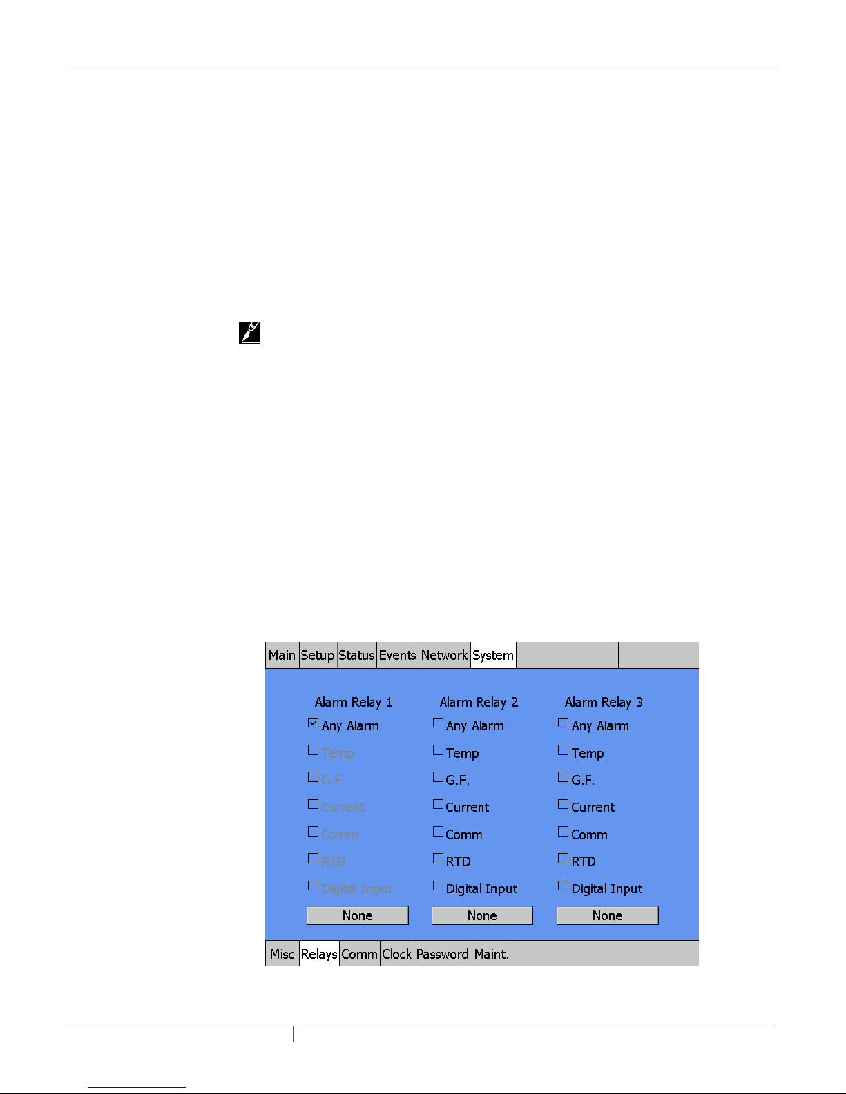
The System|Misc window provides the following controls:
• Units Toggle Button - Select Fahrenheit for °F or Celsius for ºC as temperature units.
• Screen Saver Timer Entry Field -Select the number of minutes the display remains visible
with no user activity before moving into Window Saver mode. The Window Saver mode turns the
screen to black (no backlight) and no alarms will be visible.
If an alarm occurs, a red light on the front of the enclosure illuminates. The screen must be
touched to show the Circuit’s alarm status.
IMPORTANT: Using the screen saver enhances the lifetime of the window.
Range: 1–300 minutes
Default: 20 minutes
Main Menu Timer Entry Field
This entry sets the number of minutes before the display automatically reverts to the Main
Window. Pushing any button re-starts the timer.
IMPORTANT: This time entry also determines how long a password entry will remain valid (see
System | Password section)
Range: 1–100 minutes
Default: 10 minutes
Language Entry List
This entry specifies the language used on the NGC-UIT2 display windows.
Options: Chinese, English, French, German, Russian, Spanish and others
Default: English
Mouse Toggle Button
This entry allows the USB port on the NGC-UIT2 to function with a mouse installed. If enabled, a
mouse pointer will be visible on the UIT2 screen and will allow the user to navigate through the
screens.
Options: OFF, ON
Default: OFF
3.3.32 SYSTEM | RELAYS WINDOW
This window lets you set up alarm relays.
Fig. 3.42 System |Relays window
industrial heat tracing solutions
EN-RaychemNGC30UIT2Programming-AR-H5818602/16
61 / 84
Page 62

There are three independent alarm relays in the NGC-UIT2 that can be used for remote
annunciation of alarms. Each relay can be programmed for a specific alarm type, multiple alarm
types, or none. If Any Alarm is chosen for a relay, any alarm condition will activate that relay.
3.3.33 SYSTEM | COMM WINDOW
This window lets you set up communications with host systems.
The NGC-UIT2 can be connected to a distributed control system (DCS) or host computer using
an RS-485, RS-232, or a standard Ethernet connection. All data and setup options are accessed
with communications that follow the Modbus (RTU/Modbus/TCP) protocol. To enable DCS
communications, please refer to the Raychem NGC-UIT2 Modbus Protocol document (H57880).
Selecting the Port
The NGC-UIT2 will allow you to independently configure all available ports. The "Select Port"
entry field indicates which port is being configured on the screen at the moment. Tapping on the
box will allow you to select the port you wish to configure.
Selection: RS-485 Host, RS-232 Host, Ethernet Host, RS-485 Field Bus. Depending on the port
selected, options for that port will appear.
Changing Modbus Address
The Modbus address of the NGC-UIT2 can be changed on the bottom of this screen. This Modbus
address will be used for all three of the selectable host ports. The Modbus address of the
individual ports cannot be independently set.
RS-485 Host and RS-232 Host
Fig. 3.43 System|Comm window (RS-485 Host Configuration)
industrial heat tracing solutions
EN-RaychemNGC30UIT2Programming-AR-H5818602/16
62 / 84
Page 63

Fig. 3.44 System|Comm window (RS-232 Host Configuration)
RTU Character Timeout Entry Field
This sets the time the NGC-UIT2 waits after last character is received before it determines that the
message has ended.
Range: 0–1000 milliseconds
Default: 25
Transmit Delay Entry Field
This sets the time the NGC-UIT2 will wait after it receives a message before it replies.
Range: 0-5000 milliseconds
Default: 0
Baud Rate Entry List
Allows you to select the baud rate of the external communication port.
Selection: 2400, 4800, 9600, 19200, 38400, 57600
Default: 9600
Stop Bits
Allows you to select the number of stop bits used.
Range: 1–2
Default: 2
Parity
Allows you to select what type of parity will be used.
Selection: None, Odd, Even
Default: None
industrial heat tracing solutions
EN-RaychemNGC30UIT2Programming-AR-H5818602/16
63 / 84
Page 64

Ethernet Host
Fig. 3.45 System |Comm window (Ethernet Host Configuration)
IP Address/Subnet Mask Entry Field
By default, the IP Address and Subnet Mask are automatically inserted. However, if the IP Address
or Subnet Mask needs to be changed, click on the IP Address or Subnet window and then on the
EMACB1 icon.
To enter an IP address and Subnet Mask manually, click on the IP Address tab, select "Specify an
IP Address," enter the IP Address, the Subnet Mask, and Default Gateway.
IMPORTANT: The set-up parameters above should be provided by your network administrator. The
"Name Server" tab is not applicable for this application.
Transmit Delay Entry Field
This sets the time the NGC-UIT2 will wait after it receives a message before it replies.
Range: 0–5000 milliseconds
Default: 0
industrial heat tracing solutions
EN-RaychemNGC30UIT2Programming-AR-H5818602/16
64 / 84
Page 65

RS-485 Field
Fig. 3.46 System |Comm window (RS-485 Field Configuration)
RTU Character Timeout Entry Field
This sets the time the NGC-UIT2 waits after last character is received before it determines that the
message has ended.
Range: 0–1000 milliseconds
Default: 25
Receive Message Timeout Entry Field
The received message timeout is used to extend the previously computed message timeout which
is computed automatically by the NGC-UIT2. This timeout is mainly used for extending message
timeouts in modems etc.
Range: 0–1000 milliseconds
Default: 0
Transmit Delay Entry Field
This sets the time the NGC-UIT2 will wait after it receives a message before it replies.
Range: 0–5000 milliseconds
Default: 0
Baud Rate Entry List
Allows you to select the baud rate of the external communication port.
Selection: 2400, 4800, 9600, 19200, 38400, 57600
Default: 9600
Stop Bits
Allows you to select the number of stop bits used.
Range: 1–2
Default: 2
Parity
Allows you to select what type of parity will be used.
Selection: None, Odd, Even
Default: None
industrial heat tracing solutions
EN-RaychemNGC30UIT2Programming-AR-H5818602/16
65 / 84
Page 66

3.3.34 SYSTEM | CLOCK WINDOW
This window lets you set time and date.
Fig. 3.47 System |Clock window
The System|Clock window provides the following controls:
• Time Entry Field - For entering the current time using 24 hour format.
• Date Entry Field - Allows entry of correct date from the pop-up calendar.
3.3.35 SYSTEM | PASSWORD WINDOW
This window lets you set up passwords for Level 1 and Level 2.
Fig. 3.48 System |Password window
industrial heat tracing solutions
EN-RaychemNGC30UIT2Programming-AR-H5818602/16
66 / 84
Page 67

The System|Password window provides the following controls:
• Level 1 - Allows setup of all configuration windows except for the System | Maint. window. This
Level 1 password is left “blank” from the factory; however, it can be set to a new designated
password. If a Level 1 password is chosen, the “Main Menu” timer value determines how long
the password remains active before it has to be re-entered. The password is limited to 40
characters.
• New Password Entry Field - Enter the user-defined password.
• Save new Password Action Button - Confirms password has been saved.
– Default: Level 1 disabled
• Level 2 - Allows access to System | Maintenance window, which permits clearing of Events and
program exit.
– The default password is 1234.
IMPORTANT: Change the Level 2 password after commissioning.
Old Password Entry Field
1234
New Password Entry Field
Enter your user-defined Level 2 password.
Save new Password Action Button
Confirms password has been saved.
IMPORTANT: Save and protect the Level 2 password in a secure location. Contact a Pentair
Industrial Heat Tracing Solutions representative for lost password recovery.
3.3.36 SYSTEM | MAINT. WINDOW
(Level 2 Password Required) This window allows for clearing the Events List and to exit the
program.
Fig. 3.49 System |Maint window
industrial heat tracing solutions
EN-RaychemNGC30UIT2Programming-AR-H5818602/16
67 / 84
Page 68

The System|Maint. window provides the following controls:
• Clear Events List Action Button - Clears all Events and Alarms history.
IMPORTANT: By clearing the event, all the Events and Alarms history information for all Circuits is
lost. If the program exit is chosen, heaters are no longer monitored.
Calibrate Display Action Button - starts program to calibrate the screen
Exit NGC-UIT2 Action Button
Allows user to exit Raychem NGC-30 program. This ends the monitoring of all Circuits.
IMPORTANT: Make sure you disable the Watch Dog timer located on the side of the NGC-UIT2.
Otherwise, the program will continually attempt to restart the NGC-UIT2 program.
IMPORTANT: Qualified Pentair Industrial Heat Tracing Solutions Personnel Only. It is
recommended that only Pentair Industrial Heat Tracing Solutions personnel exit the NGC-UIT2
program.
industrial heat tracing solutions
EN-RaychemNGC30UIT2Programming-AR-H5818602/16
68 / 84
Page 69

SECTION 4 APPENDICES
WARNING:
Qualified Pentair Industrial Heat Tracing Solutions Personnel Only. It is recommended that only
Pentair Industrial Heat Tracing Solutions personnel exit the NGC-UIT2 program.
APPENDIX A. NGCUIT2 SOFTWARE UPGRADE PROCESS
The NGC-30 UIT2 Software can be upgraded using a memory stick and the USB Port on the NGC-UIT2.
Step 1
– Copy the entire folder labeled "Setup", where the new NGC software version is saved, to the
USB memory stick.
Step 2
– Insert the USB flash drive with the new software into the USB port on the NGC-UIT2 Unit.
Step 3 (For UIT/UIT2 Software version 1.17.35 and higher)
– The UIT/UIT2 Software versions 1.17.35 and higher do not require power cycle. The NGC-
UIT/UIT2 can recognize the USB stick with or without power cycling.
While NGC-UIT2 Program is running, insert the USB flash drive with the new software
version into the USB Port on the Unit Wait approxi-mately one minute until the program
displays the selection screen. This screen will indicate four options, as shown below:
Fig. A.1 Window to select UIT2 software upgrade or mass configuration
Step 4
– Choose the Update NGC-UIT2 from USB Drive option by pressing that button on the screen.
Step 5
– The program will prompt you to confirm whether overwrite the current program is
industrial heat tracing solutions
acceptable, See below. Press "Yes" button.
EN-RaychemNGC30UIT2Programming-AR-H5818602/16
69 / 84
Page 70

Fig. A.2 Window to replace the existing NGC UIT2 software with the updated software
Step 6
– Wait till the load process is completed.
APPENDIX B. NGCUIT2 BACKUP PROCESS
With a USB drive, you can back up the current configuration of a UIT2. All of the configuration
settings will be saved in an XML format so that it is easily read and edited on a computer. This
includes the following:
– Circuit Database
• The currently configured circuits on the UIT2.
– Events Database
• The last 2000 events that have occurred.
– Network List
• All of the devices that appear in the Network|Device screen.
– Preferences
• The user preferences, which include parameters such as Temperature Units, Language and
Screen Timeout.
Step 1
– Insert a USB drive into the UIT2 and wait for the USB Service Panel to appear on the screen.
Fig. B.1 The USB service panel
industrial heat tracing solutions
EN-RaychemNGC30UIT2Programming-AR-H5818602/16
70 / 84
Page 71

Step 2
– Choose the Backup Database Files to USB Drive option. An input panel will appear allowing
you to choose the directory to save the backup files. If you wish, change the default directory
to fit your needs.
Fig. B.2 Backup directory prompt
Step 3
– Wait for the UIT2 to generate the backup files. A prompt will appear when the UIT2 has
successfully created the files.
Fig. B.3 Backup directory prompt
industrial heat tracing solutions
EN-RaychemNGC30UIT2Programming-AR-H5818602/16
71 / 84
Page 72

APPENDIX C. PROPORTIONAL CONTROL
Table C.1 Proportional Control Temperature Band
Control Sensor Temperature Duty Cycle
Setpoint + 2.22°C 0%
Setpoint + 1.11°C 50%
Setpoint 100%
Table C.2 Approximate Time On/Off for 50/60 Hz Frequencies
Temperature On Time/
Set Point + 2.22°C 0 1000 Set Point + 1.06°C 525 475
Set Point + 2.17°C 25 975 Set Point + 1.00°C 550 450
Set Point + 2.11°C 50 950 Set Point + 0.94°C 575 425
Set Point + 2.06°C 75 925 Set Point + 0.89°C 600 400
Set Point + 2.00°C 100 900 Set Point + 0.83°C 625 375
Set Point + 1.94°C 125 875 Set Point + 0.78°C 650 350
Set Point + 1.89°C 150 850 Set Point + 0.72°C 675 325
Set Point + 1.83°C 175 825 Set Point + 0.67°C 700 300
Set Point + 1.78°C 200 800 Set Point + 0.61°C 725 275
Set Point + 1.72°C 225 775 Set Point + 0.56°C 750 250
Set Point + 1.67°C 250 750 Set Point + 0.50°C 775 225
Set Point + 1.61°C 275 725 Set Point + 0.44°C 800 200
Set Point + 1.56°C 300 700 Set Point + 0.39°C 825 175
Set Point + 1.50°C 325 675 Set Point + 0.33°C 850 150
Set Point + 1.44°C 350 650 Set Point + 0.28°C 875 125
Set Point + 1.39°C 375 625 Set Point + 0.22°C 900 100
Set Point + 1.33°C 400 600 Set Point + 0.17°C 925 75
Set Point + 1.28°C 425 575 Set Point + 0.11°C 950 50
Set Point + 1.22°C 450 550 Set Point + 0.06°C 975 25
Set Point + 1.17°C 475 525 Set Point + 0.00°C 1000 0
Set Point + 1.11°C 500 500
Second
(ms)
Off Time/
Second
(ms)
Temperature On Time/
Second
(ms)
Off Time/
Second
(ms)
industrial heat tracing solutions
EN-RaychemNGC30UIT2Programming-AR-H5818602/16
72 / 84
Page 73

APPENDIX D. PROPORTIONAL AMBIENT SENSING CONTROL PASC
The power to the heat tracing is proportioned based upon on the ambient temperature. If the
ambient temperature is at or below the “minimum design ambient +3°F” the heaters will be on
100%. If the measured ambient is at or above the “maintain temperature –3°F” the heaters will be
on 0%.
For any measured ambient between “minimum design ambient” and “maintain temperature,” the
heaters will be on a percentage of the time equal to (maintain temperature – measured ambient) /
(maintain temperature – minimum design temperature).
Duty cycle
0% 100%
Ambient temperature
Minimum
ambient
temperature
APPENDIX E. RTD DEVICE / RTD NUMBER ENTRY WINDOWS
MONITOR-ONLY MODE
Select one to four RTDs to monitor the temperature of a pipe, vessel etc. An RTD can be used from
another Relay/RTD or from a RMM2 module mounted in the panel or remotely.
CONTROL MODE WITH LOCAL RTD INSTALLED
If the local RTD is installed, up to three additional RTDs can be used to monitor the temperature
of the pipe, vessel, etc. An RTD can be used from another Relay/RTD or from a RMM2 module
mounted in the panel or remotely. If more than one RTD is assigned to a Circuit, the NGC-UIT2 will
display the lowest temperature detected on the main window. However, it will alarm (high and low
temperature) based upon all RTDs assigned to that Circuit.
CONTROL MODE WITHOUT LOCAL RTD INSTALLED
If the local RTD is not installed, up to four additional RTDs can be used to monitor the temperature
of the pipe, vessel, etc. An RTD can be used from another Relay/RTD or from a RMM2 module
mounted in the panel or remotely. If more than one RTD is assigned to a Circuit, the NGC-UIT2 will
display the lowest temperature detected on the main window. However, it will alarm (high and low
temperature) based upon all RTDs assigned to that Circuit.
IMPORTANT: If an address entered is lower than any NGC-30-CRM/-CRMS board found on the
system, the Raychem NGC-30 software defaults to 0. Since 0 is not a valid address for any board,
selecting 0 tells the program that this Circuit will not be used for any output control; by default, it
will be a “Monitoring Only” Circuit. This is the method for setting up a Circuit as an “Alarm Only”
channel.
IMPORTANT: The NGC-UIT2 displays the parameters of heaters. It also is a means to input
information to the NGC-30-CRM/-CRMS. Once the system is set up, the NGC-30-CRM/-CRMS
controls the heater Circuits, and even if the NGC-UIT2 display loses communications between
the NGC-30-CRM/-CRMS and the NGC-UIT2, the heaters are still being controlled by the NGCCRM/-CRMS. A feature of the -CRM/-CRMS is that if it is hardwired to the system, the system still
continues to work.
Pipe
maintain
temperature
industrial heat tracing solutions
EN-RaychemNGC30UIT2Programming-AR-H5818602/16
73 / 84
Page 74

APPENDIX F. TERMS AND DEFINITIONS
Amps Heater current amperes
Control Temperature The lowest temperature from the RTDs assigned to a Circuit
°C or °F The control temperature
DB Dead Band
Device Address Network address for specific hardware devices attached to the NGC-UIT2
EMR Electrical Mechanical Relay
G.F. Heater ground-fault current
ID Identification ‘tag’ for the Circuit
Circuit Short for ‘Control Circuit’, the basic organizing structure of the
Raychem NGC-30
RTD Resistance Temperature Detectors
RTD Number This is the number of the RTD determined by the physical point of
connection to a networked device
Set Pt Set Point is the desired maintain temperature
SSR Solid State Relay
Status Relay (heater on, off or trip) and communication status
Table F.1
Data Entry Type Description
Entry Window In Setup Windows, any white entry box will populate via a pop-up
Entry List Allows choices from a list of data
Action Button Prompts before performing a task
Toggle Button Toggles between two actions
IMPORTANT: When a button’s word(s) is grayed out, no action can be taken
entry window
APPENDIX G. CONFIGURATION SPREADSHEET
An electronic version of the Raychem NGC-30 Configuration Spreadsheet is available on our web
site, www.pentairthermal.com on the NGC-30 product page under Heat Tracing. Select “Raychem
NGC-30 Configuration Spreadsheet” from the list to download.
A printed copy of the spreadsheet is available for use on the following 3 pages. However,
information will have to be manually entered into the NGC-UIT2.
Regardless of which medium you use, retain a copy for future reference or backup.
industrial heat tracing solutions
EN-RaychemNGC30UIT2Programming-AR-H5818602/16
74 / 84
Page 75

NGC-UIT2 Circuit Setup Worksheet (page 1 of 4)
Circuit #
Input
Required
1
2
3
4
5
6
7
8
9
10
11
12
13
14
15
16
17
18
19
20
21
22
23
24
25
26
27
28
29
30
31
32
33
34
35
36
37
38
39
40
Circuit ID
(Up to 40
Char)
Default = ID
circuit#
Circuit
Enable
Input
Required
Setup | Ciruit Screen
Input Required
Relay
Relay
Address
Number
Default = 0 Default = 0
Control
Mode
Input
Required
FailSafe
State
(Power Off /
Power On)
Default =
Power Off
SETUP | RTDs Screen
Local/A Local/B Local/C Local/D
RTD Device
RTD No. RTD Mode
Address
Default = 0 Default = 0
Default =
Control
RTD Device
RTD No. RTD Mode
Address
Default = 0 Default = 0
Default =
Control
RTD Device
RTD No. RTD Mode
Address
Default = 0 Default = 0
Default =
Control
RTD Device
RTD No. RTD Mode
Address
Default = 0 Default = 0
Default =
Control
Device Device Type Switch Setting Device Address
NGC-30-CRM/CRMS Relay Output / RTD 1 – 99 1 – 99
RMM2 RTD 0 – F 32 – 47
PLI RTD 1 – 99 1 – 99
industrial heat tracing solutions
EN-RaychemNGC30UIT2Programming-AR-H5818602/16
75 / 84
Page 76

NGC-UIT2 Circuit Setup Worksheet (page 2 of 4)
1
2
3
4
5
6
7
8
9
10
11
12
13
14
15
16
17
18
19
20
21
22
23
24
25
26
27
28
29
30
31
32
33
34
35
36
37
38
39
40
Setpoint Deadband
Default =
Default
50ºF
= 5ºF
High Temp
Alarm
Default =
300ºF
Low Temp
Alarm
Default =
10ºF
Setup | Temp Screen
High Limit
Cut-Out
Enable
Default =
Disable
High Limit
Cut-Out
Temp
Default =
900ºF
Low Limit
Cut-Out
Enable
Default =
Disable
Low Limit
Cut-Out
Temp
Default =
-94ºF
Low Limit
Cut-Out
Deadband
Default
= 5ºF
Low Limit
Cut-Out
Latching
Default =
NonLatching
Temperature
Alarm Filter
Default =
900 Seconds
Setup | G.F. Screen Setup | Current Screen Setup | Voltage
G.F.
G.F.
G.F. Trip
Low
Current
Alarm
Default =
20mA
Current
Trip
Default =
30mA
(Enable/
Disable
Default =
Enable
Current
Alarm
Default =
5.0A
High
Current
Alarm
Default =
30.0A
Power
Limit
Default
= 100
Low
Voltage
Alarm
Default =
90V
High
Voltage
Alarm
Default =
270V
Device Device Type Switch Setting Device Address
NGC-30-CRM/CRMS Relay Output / RTD 1 – 99 1 – 99
RMM2 RTD 0 – F 32 – 47
PLI RTD 1 – 99 1 – 99
RMM-DI Digital Input 0-F(High), 0-F(Low) 1-247
RMC Digital Input / Relay Output 1-255 1-247
industrial heat tracing solutions
EN-RaychemNGC30UIT2Programming-AR-H5818602/16
76 / 84
Page 77

NGC-UIT2 Circuit Setup Worksheet (page 3 of 4)
PLI Setup | PASC Screen Setup | Maintenance Screen Setup | Input Screen
Used only in PASC Control Mode
PLI Update
Interval
Default - 10
1
2
3
4
5
6
7
8
9
10
11
12
13
14
15
16
17
18
19
20
21
22
23
24
25
26
27
28
29
30
31
32
33
34
35
36
37
38
39
40
Min.
Min. Pipe
Ambient
Temp.
Default =
Min
-40ºF
Size
Default =
0.5 Inch
Power
Adjust
Default =
100%
Power Cycle Start Time
Hour
Default = 06
Minute
Default = 00
Power Cycle
Test Interval
Default =
0 Hrs
Heater
Time Alarm
Default =
100,000 hrs
Relay
Power
Cycle
Alarm
Default =
500,000
Power
Input
Input
Address
Number
Default = 0 Default = 0 Default = 0 Default = 0
CB Trip
Input
Address
CB Trip
Input
Number
CB Trip
Input State
Default =
Close
User Alarm
Input
Address
Default = 0 Default = 0
User Alarm
Input
Number
User Alarm
Input
State
Default =
Open
User Alarm
Input Text
Default=User
text
Device Device Type Switch Setting Device Address
NGC-30-CRM/CRMS Relay Output / RTD 1 – 99 1 – 99
RMM2 RTD 0 – F 32 – 47
PLI RTD 1 – 99 1 – 99
RMM-DI Digital Input 0-F(High), 0-F(Low) 1-247
RMC Digital Input / Relay Output 1-255 1-247
industrial heat tracing solutions
EN-RaychemNGC30UIT2Programming-AR-H5818602/16
77 / 84
Page 78

Circuit #
Input
Required
1
2
3
4
5
6
7
8
9
10
11
12
13
14
15
16
17
18
19
20
21
22
23
24
25
26
27
28
29
30
31
32
33
34
35
36
37
38
39
40
Setup | Load Shed
European Version Only (NGC-20)
Load Shed
Default =
Enable
Disable
Load Shed
Fail Safe
Default =
Disable
NGC-UIT2 Circuit Setup Worksheet (page 4 of 4)
Load Shed
Mask
Default = 0
Device Device Type Switch Setting Device Address
NGC-30-CRM/CRMS Relay Output / RTD 1 – 99 1 – 99
RMM2 RTD 0 – F 32 – 47
PLI RTD 1 – 99 1 – 99
RMM-DI Digital Input 0-F(High), 0-F(Low) 1-247
RMC Digital Input / Relay Output 1-255 1-247
industrial heat tracing solutions
EN-RaychemNGC30UIT2Programming-AR-H5818602/16
78 / 84
Page 79

INDEX
INDEX OF FIELDS AND WINDOWS
Item Display Window within Program Main Reference Pages
Address Network|Devices,
Alarm Relays Main, System|Relays 61, 62
Always Off Setup|Circuit (subwindow) 18, 31, 32, 36
Always On Setup|Circuit (subwindow) 18, 31, 32, 36
Amps Main 4, 29, 74
Any Alarm System|Relays Pop-up 53, 62
Assign Relay Number Setup|Relay 17
Baud Rate System|Comm 63, 65
Circuit Setup|Circuit, Status|Circuit 5, 10, 12, 14, 23, 27, 42, 44, 49, 51, 55,
Clear Events List System|Maint. 68
Comm Alarm System|Filters, Events
Control Temp Status|Circuit, Status|Min/Max 45, 51, 55
Current Status|Circuit 5, 21, 22, 29, 32, 38, 42, 45, 48, 50, 51,
Current Alarm System|Relays 21, 22, 38, 53, 54
Date System|Clock 7, 13, 54, 66
Dead Band (or DB) Setup|Temp, Main 18, 20, 29, 32, 35, 45, 74
Delete Setup|Circuit 30
Device Network|Devices, Network|Maint. 8, 10, 14, 16, 17, 20, 25, 27, 28, 31, 32,
Device Address Setup|Circuit, Network|Remove 10, 14, 16, 17, 20, 25, 28, 31, 42, 56, 60,
Disabled Setup|Circuit 23, 30, 37, 38, 54, 67
Enabled Setup|Circuit 22, 23, 30, 37, 38, 61
Exit NGC-UIT2 System|Maint. 68
°F Main, Status|RTDs,
Fail Safe Setup|Circuit 19, 33, 53, 54
Ground Fault (or G.F.) Main, Setup|G.F., Status|Circuit 5, 37, 42, 54
Ground-Fault Current
Alarm
Ground-Fault Current
Trip
Ground-Fault Alarm Setup|G.F., System|Filters, Events
Ground-Fault Trip Setup|G.F., Events (Alarm
Heater Time Alarm Setup|Maint, Events 41, 53, 54
Heater Time On Status|Maint. 52, 54
High Current Alarm Setup|Current, Events (Alarm
High Limit Cut-Out Setup|Temp 20, 36, 37
Network|Relays, Network|RTDs,
Network|Maint.
(subwindow), System|Relays
Network|RTDs
Setup|G.F. 21, 53
Setup|G.F. 21
(subwindow),
System|Relays
Heading)
Heading)
7, 10, 14, 16,17, 20, 25, 28, 31, 40, 42,
48, 49, 56, 57, 60, 62, 64, 73
58, 59, 61, 70, 73
53, 54
53, 55, 59, 66, 69, 70, 74
34, 42, 45, 54, 56, 60, 70, 73
74
29, 32, 35, 37, 39, 43, 61, 73, 74
22, 37, 38, 54,
22, 38, 53, 54
22, 38, 53, 54
industrial heat tracing solutions
EN-RaychemNGC30UIT2Programming-AR-H5818602/16
79 / 84
Page 80

Item Display Window within Program Main Reference Pages
High Temp Alarm Setup|Temp, Events (Alarm
High Voltage Alarm Setup|Maint. 21, 38, 53
ID Setup|Circuit, Status|Circuit,
IP Address System|Comm 64
Language System|Misc 6, 13, 61, 70
Level 1 password System|Password 67
Level 2 password System|Password 67
Low Current Alarm Setup|Current, Events (Alarm
Low Temp Alarm Setup|Temp, Events (Alarm
Low Voltage Alarm Setup|Maint. 21, 38, 54
Main Menu Timer System|Misc 61
Min Ambient Temp Setup|PASC 39
Min Pipe Size Setup|PASC 39
Modbus Address System|Comm 62
Mode Setup|Circuit, Status|Circuit,
Monitor Only Setup|Circuit (subwindow) 28, 31, 32
Mouse System|Misc 61
New Password System|Password 67
Next PLI Update Status|PLI 48
Next Relay Switch Status|PASC 47
On/Off Mode Select Pop-up 4, 12, 14, 20, 22, 25, 28, 43, 45, 49, 52,
Off Count Status|PASC 46
On Count Status|PASC 46
Parity System|Comm 63, 65
PASC Setup|PASC, Setup|Circuit
Password - Level 1 System|Password 67
Password - Level 2 System|Password 67
PLI Address Network|PLI 57
PLI Update Interval Setup|PLI 40
Power Adjust Setup|PASC 39
Power Cycle Test
Interval
Power Cycle Start Time Setup|Maint 41
Power Limit Setup|Current 22, 38
Proportional Setup|Circuit (subwindow) 4, 18, 31, 32, 35, 36, 72, 73
Read/Write Port System|Comm 6, 7, 9, 12, 20, 29, 33, 40, 48, 52, 58, 70,
Relay Status|Circuit, Network|Relays 5, 6, 10, 12, 16, 17, 20, 21, 27, 29, 38, 41,
Relay Cycle Alarm Setup|Maint 41, 54, 55
Relay Cycle Count Status|Maint. 52
Relay Number Setup|Circuit 16, 17, 31
Heading)
Main
Heading)
Heading)
Network|PLI
(subwindow)
Setup|Maint 41
20, 35, 53, 54
15, 29, 30, 45, 74
22, 38, 53, 54
20, 35, 53, 54
18, 20, 26, 30, 34, 36, 37, 39, 44, 46, 53,
54, 57, 61, 73
54, 56, 57, 61, 62, 64, 68, 70, 72
63, 65
74
43, 45, 47, 49, 52, 54, 56, 58, 62, 73
industrial heat tracing solutions
EN-RaychemNGC30UIT2Programming-AR-H5818602/16
80 / 84
Page 81

Item Display Window within Program Main Reference Pages
Relay Output Setup|Circuit 6, 20, 30, 38, 43, 45, 54, 56
Relay State Status|PASC 47, 48
Remove (Network
Device Address)
Reset Heater Time Status|Maint. 52
Reset Relay Cycle
Count
Resources Network|Devices 27, 56
RTDs Status|RTDs, Network|RTDs
Network|Remove
Status|Maint. 52
56,60
4, 14, 19, 20, 24, 27, 33, 37, 45, 46, 48,
56, 58, 73, 75, 79
RTD Device Address Setup|RTDs 20
RTD Failure Events (Alarm Heading) 54, 55
RTD Number Setup|RTDs 73, 74
RTD Mode Setup|RTDs 34, 46, 75
RTU Character Timeout System|Comm
Subnet Mask System|Comm 64
Save New Password System|Password 67
Select Port System|Comm 62
Screen Saver Timer System|Misc
State Network|Relays 8, 29, 32-33, 42, 45, 47, 48, 50, 53, 55,
Status Status|Circuit, Main 6, 10,11, 23, 27, 29, 30, 33, 38, 43, 48,
Stop Bits System|Comm 63, 65
Subnet Mask System|Comm 64
Temp Alarm System|Relays 20, 35, 53, 54
Temperature Alarm System|Filters, System|Relays 20, 36, 76
Temperature Alarm
Filter
Time System|Clock, Events 13, 20, 25, 32, 36, 38, 41, 43, 47, 57, 61,
Transmit Delay System|Comm 63, 65
Units System|Misc 6, 13, 61, 70
Update Network Network|Devices
Version Network|Devices
Voltage Setup|Voltage, Status|Voltage
Setup|Temp 20, 36
63, 65
61
59, 74, 75
50, 53, 55, 58, 59, 61, 74
63, 66, 72, 73
14, 25, 27, 28, 56
6, 69, 74
5, 18, 21, 31, 32, 38, 47, 51, 53, 55,
WINDOW LOCATIONS
Window Page
Events 11, 21, 33, 38, 52, 55, 67, 68, 70
Main 10, 12, 19, 23, 27, 29, 30, 32, 61, 67, 73
Network | Devices 14, 25, 26, 28, 31, 33, 56
Network | Maint 59
Network | PLI 57
Network | Relays 58
Network | Remove 60
Network | RTDs 58
industrial heat tracing solutions
EN-RaychemNGC30UIT2Programming-AR-H5818602/16
81 / 84
Page 82

Setup | Circuit 22, 30, 31, 45
Setup | Current 15, 19, 22, 30, 34, 44, 54
Setup | Maint 41
Setup | PASC 39
Setup | PLI 40
Setup | RTDs 19, 33, 34
Setup | Temp 20, 35
Status | Circuit 38, 44, 45, 55
Status | Maint. 52
Status | Min 51
Status | PASC 46
Status | PLI 47, 48
Status | RTDs 46
Status | Voltage 47
System | Clock 13, 66
System | Comm 62, 63
System | Maint. 54, 67, 68
System | Misc 6 , 13, 60, 61
System | Password 61, 66, 67
System | Relays 61
industrial heat tracing solutions
EN-RaychemNGC30UIT2Programming-AR-H5818602/16
82 / 84
Page 83

Page 84

WWW.PENTAIRThERmAl.COm
NORTh AmERICA
Tel: +1.800.545.6258
Fax: +1.800.527.5703
Tel: +1.650.216.1526
Fax: +1.650.474.7111
thermal.info@pentair.com
Pentair is owned by Pentair or its global affiliates. All other trademarks are the property of their respective owners. Pentair reserves the right to change
specifications without prior notice.
© 2006-2016 Pentair.
EuROPE, mIddlE EAsT, AfRICA
Tel: +32.16.213.511
Fax: +32.16.213.603
thermal.info@pentair.com
industrial heat tracing solutions
AsIA PACIfIC
Tel: +86.21.2412.1688
Fax: +86.21.5426.2937
cn.thermal.info@pentair.com
EN-RaychemNGC30UIT2Programming-AR-H5818602/16
lATIN AmERICA
Tel: +1.713.868.4800
Fax: +1.713.868.2333
thermal.info@pentair.com
84 / 84
 Loading...