

Page 1

HWAT System
INSTALLATION AND OPERATION MANUAL
FOR HOT WATER TEMPERATURE MAINTENANCE
SYSTEMS FOR THERMALLY INSULATED PIPES
THERMAL MANAGEMENT SOLUTIONS WWW.THERMAL.PENTAIR.COM
Page 2

ii
Raychem-IM-H57548-HWATsystem-EN 16/08
Important Safeguards and Warnings
WARNING: FIRE AND SHOCK HAZARD
Raychem HWAT Systems must be installed
correctly to ensure proper operation and to prevent
shock and fire. Read these important warnings and
carefully follow all the installation instructions.
• To minimize the danger of fire from sustained
electrical arcing if the heating cable is damaged or
improperly installed, and to comply with Pentair
Thermal Management requirements, agency certifications, and national electrical codes, ground-fault
equipment protection must be used on each heating
cable branch circuit. Arcing may not be stopped by
conventional circuit breakers.
• Approvals and performance are based on the use of
Pentair Thermal Management parts only. Do not substitute parts or use vinyl electrical tape.
• Bus wires will short if they contact each other. Keep
bus wires separated.
• Connection kits and heating cable ends must be kept
dry before and during installation.
• The black heating cable core is conductive and can
short. They must be properly insulated and kept dry.
• Damaged bus wires can overheat or short. Do not
break bus wire strands when preparing the cable for
connection.
• Damaged heating cable can cause electrical arcing or fire. Do not use metal attachments such as
pipe straps or tie wire. Use only Pentair Thermal
Management approved tapes and cable ties to secure
the cable to the pipe.
• Do not attempt to repair or energize damaged cable.
Remove damaged cable at once and replace with a
new length using the Raychem RayClic-S splice kit.
Replace damaged connection kits.
• Use only fire-resistant insulation which is
compatible with the application and the maximum
exposure temperature of the system to be traced.
Page 3

iii
Raychem-IM-H57548-HWATsystem-EN 16/08
Table of Contents
1
General Information 1
1.1 Use of the Manual 1
1.2 Safety Guidelines 2
1.3 Typical HWAT System 2
1.4 Electrical Codes 3
1.5 Approvals 3
1.6 Warranty 4
1.7 Trade Coordination 4
1.8 General Installation Notes 5
1.9 Tools Required 6
2
Heating Cable Verification and Selection 7
2.1 Heating Cable 7
3
Heating Cable Installation 8
3.1 Heating Cable Storage 8
3.2 Pre-Installation Checks 8
3.3 Installation 8
4
Heating Cable Components 14
4.1 General Connection Kit Information 14
5
Control and Monitoring 16
5.1 HWAT-ECO and ACCS-30 Controllers 16
6
Thermal Insulation 17
6.1 Insulating the System 17
6.2 Insulation Installation 17
7
Power Supply and Electrical Protection 20
7.1 Voltage Rating 20
7.2 Circuit Breaker Sizing 20
7.3 Electrical Loading 20
7.4 Ground-Fault Protection 21
8
Commissioning and Preventive Maintenance 22
8.1 Tests 22
8.2 Preventative Maintenance 24
9
Test Procedures 25
9.1 System Tests 25
9.2 Fault Location Tests 31
9.3 Cable and Connection Continuity
Page 4

iv
Raychem-IM-H57548-HWATsystem-EN 16/08
10
Test Procedures 34
11
Troubleshooting Guide 38
Page 5

1
Raychem-IM-H57548-HWATsystem-EN 16/08
1.1 Use of the Manual
This installation and operation manual is for
Raychem HWAT Hot Water Temperature Maintenance
systems installed on thermally insulated pipes only.
This manual details how to install and operate
an HWAT system. The HWAT System includes the
HWAT-R2 heating cables, RayClic connection kits,
and the HWAT-ECO or ACS-30 controllers. It is
important to review this manual and the following
documents with the installing contractor:
• HWAT System Product Selection & Design Guide
(H57538)
• HWAT-ECO Data Sheet (H57339)
• ACS-30 Mulitpoint Commercial heat-tracing
Control System Data Sheet (H58261)
• HWAT Heating Cable Data Sheet (H57512)
• RayClic Connection System Data Sheet (H57545)
• HWAT-ECO Installation and Operation Manual
(H57340)
• ACS-30 Programming Guide (H58692)
For additional information, contact:
Pentair Thermal Management
7433 Harwin Drive
Houston, TX 77036
USA
Tel: +1.800.545.6258
Tel: +1.650.216.1526
Fax: +1.800.527.5703
Fax: +1.650.474.7711
thermal.info@pentair.com
www.thermal.pentair.com
Important: For the Pentair Thermal Management
warranty and agency approvals to apply, the instructions that are included in this manual and product
packages must be followed.
1
General Information1 General Information
Page 6

2
Raychem-IM-H57548-HWATsystem-EN 16/08
1.2 Safety Guidelines
The safety and reliability of any heat-tracing system
depends on the quality of the products selected, and
on proper design, installation, and maintenance.
Incorrect design, handling, installation, or maintenance of any of the system components can cause
underheating or overheating of the pipe, or damage to the heating cable system, and may result in
system failure, electric shock, or fire. The guidelines and instructions contained in this guide are
important. Follow them carefully to minimize these
risks and to ensure that the HWAT System performs
reliably.
Pay special attention to the following:
• Instructions marked
Important
• Warnings marked
WARNING
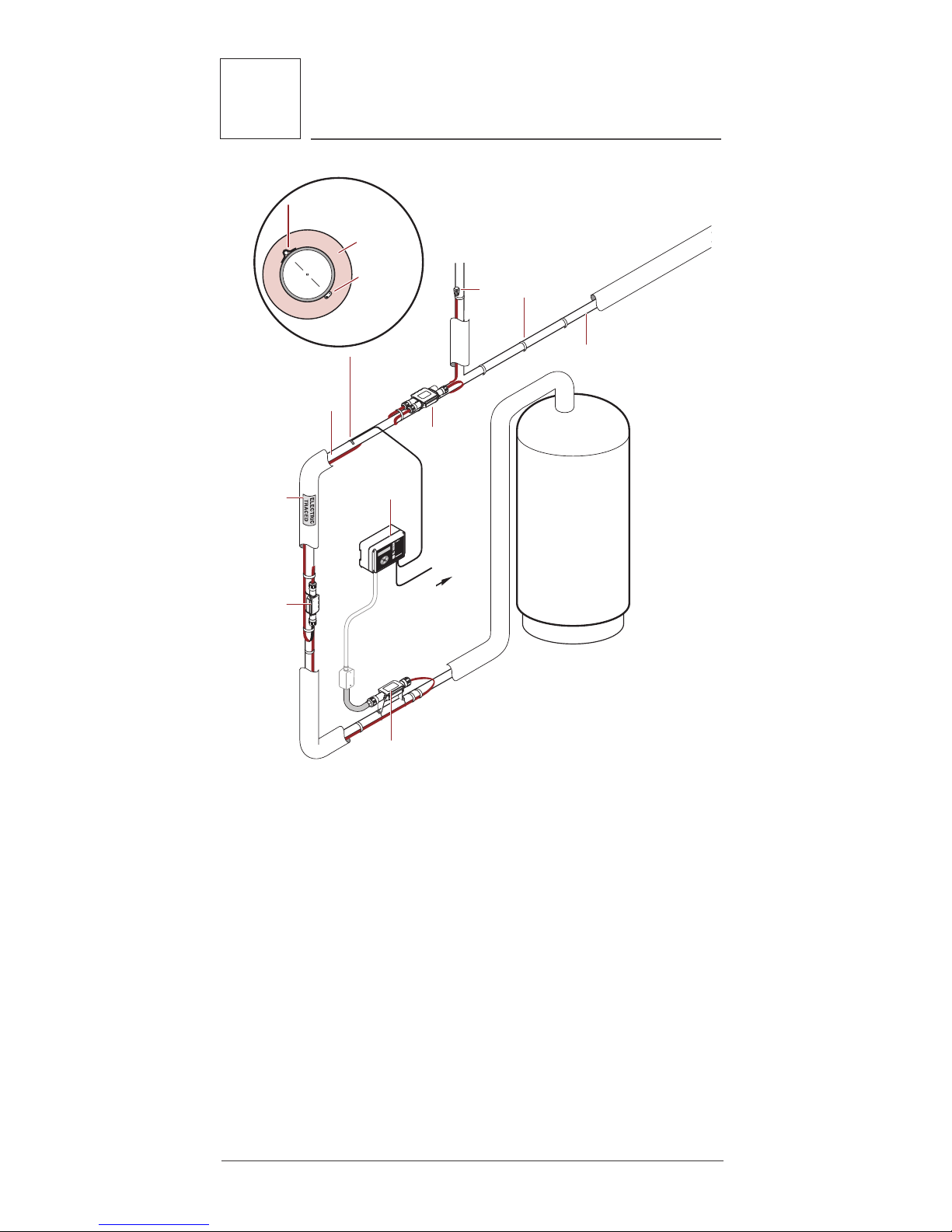
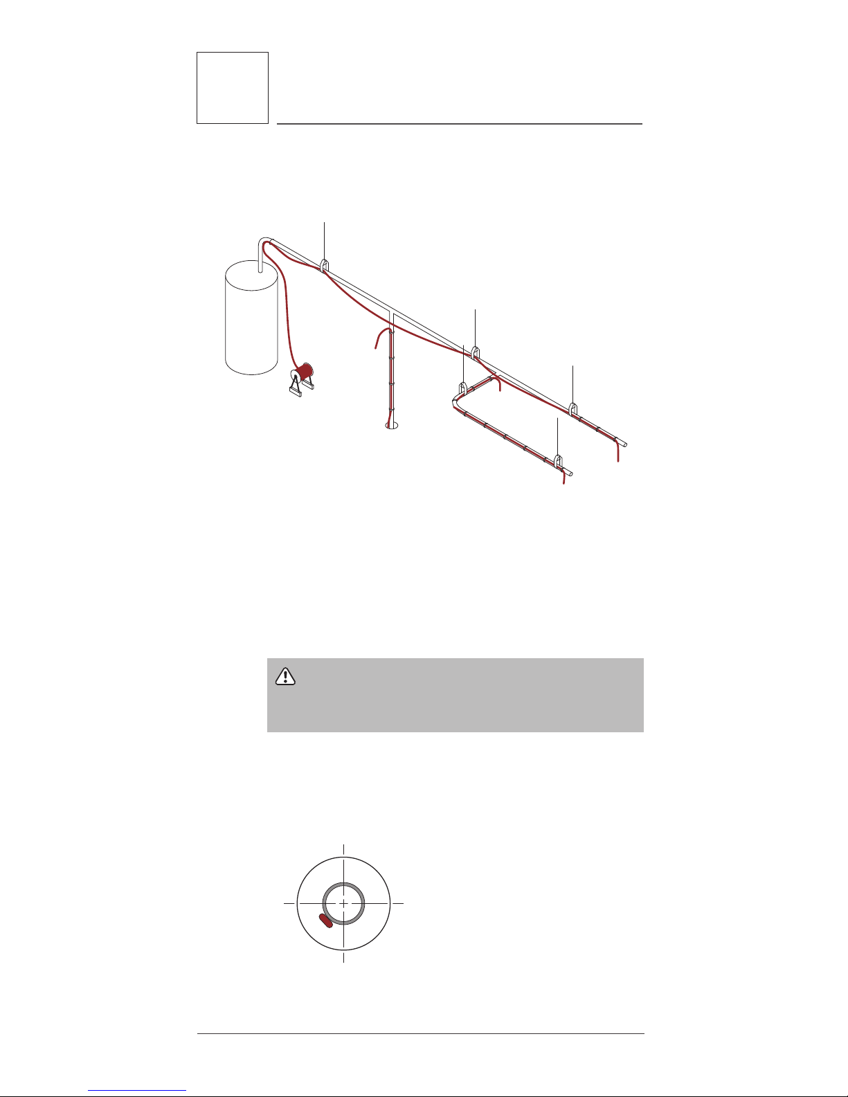
1.3 Typical HWAT System
A typical HWAT System is shown is Figure 1. The
heating cable is cut to length in the field and is
attached to the pipe with glass tape. A power connection kit connects the heating cable bus wires to
power in a junction box. RayClic tees and splices
accommodate pipe branches to connect two or three
heating cables together. An end seal kit is used to
terminate the end of the heating cable. A controller
is used to set the maintain temperature and improve
energy savings.
1
General Information
Page 7
3
Raychem-IM-H57548-HWATsystem-EN 16/08
Splice
To power
distribution
panel
Note: Partial pipe insulation
shown here for clarity.
All pipes must be fully
insulated
End
seal
Tee
Thermal
insulation
Heating
cable
Pipe
temperature
sensor
Temperature
sensor
Heating
cable
Insulation
Glass
tape
Power
connection
Controller
To BMS
ETL
label
180°
Figure 1: Typical HWAT heating cable system
1.4 Electrical Codes
Section 427 of the National Electrical Code (NEC),
and Part 1, Section 62 of the Canadian Electrical
Code (CEC), in particular, govern the installation of
electrical heat-tracing systems used on hot water
pipes. All installations must be in compliance with
this and any other applicable national or local codes.
1.5 Approvals
HWAT-R2 heating cable and RayClic connection kits,
are UL Listed and CSA certified for use in non-hazardous locations. The HWAT-ECO controller is c-ULus Listed and the ACS-30 controller is c-CSA-us certified (ACS-UIT) and c-UL-us Listed (ACS-PCM2-5) to
1
General Information
Page 8

4
Raychem-IM-H57548-HWATsystem-EN 16/08
US and Canadian standards for us in non-hazardous
locations. Refer to the specific product data sheets
for details.
1.6 Warranty
Pentair Thermal Management standard limited warranty applies to all products.
An extension of the limited warranty period to ten
(10) years from the date of installation is available
if a properly completed on-line warranty form is
completed within (30) days from the date of installation. The extension is valid for the HWAT-R2 heating
cable, RayClic connection kits and accessories, but
not the HWAT-ECO or ACS-30 controllers. You can
access the complete warranty on
www.thermal.pentair.com.
1.7 Trade Coordination
Installation of an HWAT System can involve or impact
the work of numerous trades. Therefore, effective
and early coordination between trades is a critical
aspect of all HWAT System Installations. The installation of the heating cable and connections must be
properly scheduled, along with the scheduling of the
risers and insulation installation.
This guide will assist the installer throughout the
installation process and must be reviewed by all
affected trades before installation of the HWAT
System begins. In a fast-track job, the HWAT System
must be considered a critical path item: the pipe,
heating cable, insulation, and wallboard must all be
installed in the proper order, since the heating cable
cannot be installed later. If, for example, the walls
go up before the heating cable commissioning tests
have been completed, it may be necessary to remove
the walls in order to repair a damaged or improperly
installed system.
Ensuring that the installation of the HWAT System
is included in the overall construction schedule
will help ensure a successful and trouble-free
installation.
1
General Information
Page 9

5
Raychem-IM-H57548-HWATsystem-EN 16/08
1.8 General Installation Notes
Read and observe the instructions in this guide
to insure that the HWAT System is installed
successfully.
• Accidental damage to the system can be minimized
during construction by installing thermal insulation
on the pipe immediately after the pipe has been
traced and the heating cable has been tested.
• Read all installation documentation to familiarize
yourself with the system components.
• Read and follow all warnings and recommendations. All involved trades should review this entire
guide and assess the recommendations applicable
to their scope of work.
• All heat-traced pipes and equipment must be thermally insulated. Insulation is an important part
of the HWAT System. For an effective system, the
fiberglass insulation must be a specific thickness
for each specific pipe size as detailed in Table 2 on
page17.
• Do not install the HWAT System below the minimum installation temperature.
– The minimum installation temperature for HWAT
heating cables is 0°F (–18°C)
– The minimum installation temperature for HWAT-
ECO is 40°F (5°C).
• Ensure that your water heater temperature is set
at your desired pipe maintain temperature.
• Do not energize cable when it is coiled or on the
reel.
• Never use metal tie wire or pipe straps to secure
heating cables to pipes.
Important: Exceeding 185°F (85°C) for HWAT-R2
will decrease the power output of the heating cables
over time.
1
General Information
Page 10

6
Raychem-IM-H57548-HWATsystem-EN 16/08
1.9 Tools Required
For installing cable and connection kits:
• Utility knife
• Diagonal cutters
• Cable cutters
• Tape measure
• Screwdriver
• Heat gun or propane torch
For testing the heating cable:
• Megohmmeter 2500 Vdc
• Multimeter (voltage, resistance and capacitance)
1
General Information
Page 11
7
2
Heating Cable Verification and
Selection
Raychem-IM-H57548-HWATsystem-EN 16/08
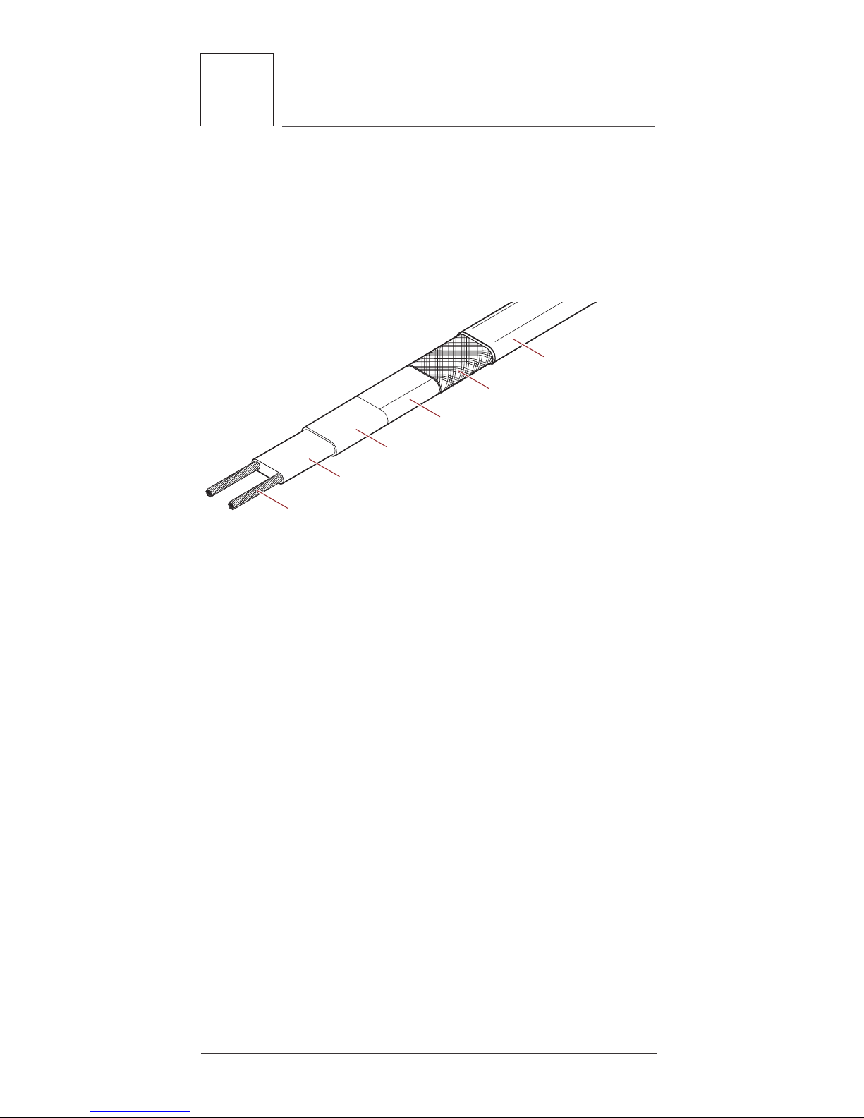
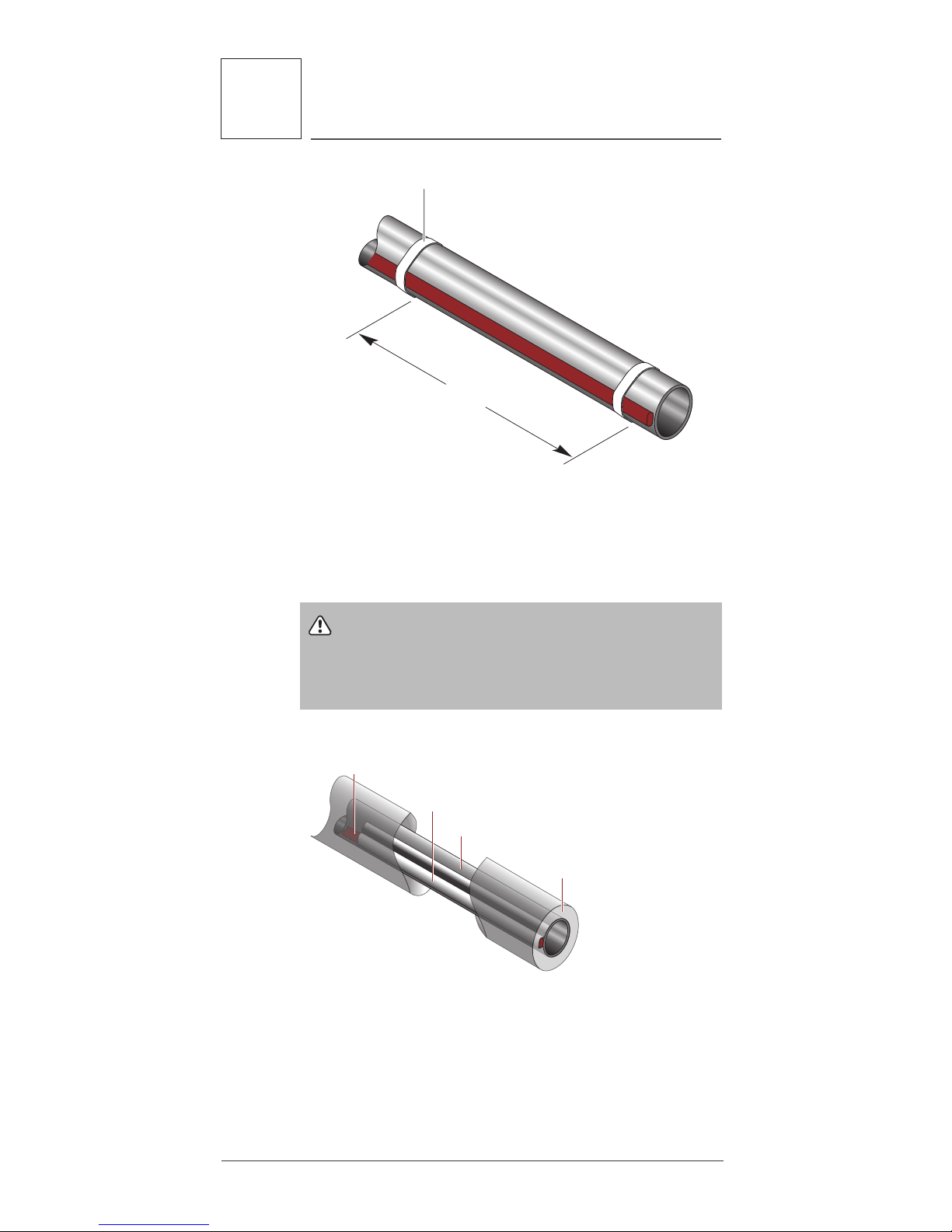
2.1 Heating Cable
The HWAT System includes HWAT-R2 heating cable
designed to maintain the piping at specific temperature settings with the use of the HWAT-ECO or ACS30 controllers. Figure 2 shows the construction of
the heating cable.
Nickel-plated copper bus wires
Self-regulating conductive core
Polymer-coated aluminum wrap
Tinned-copper braid
Modified polyolefin
outer jacket
Modified polyolefin inner jacket
Figure 2: HWAT-R2 heating cable
The minimum control setpoint for HWAT-R2 is 105°F
(40°C). The maximum control setpoint for HWAT-R2
is 140°F (60°C).
2 Heating Cable Verification and
Selection
Page 12

8
3
Heating Cable Installation
Raychem-IM-H57548-HWATsystem-EN 16/08
3.1 Heating Cable Storage
• Store the heating cable in a clean, dry location.
Temperature range: 0°F (–18°C) to 140°F (60°C).
• Protect the heating cable from mechanical
damage.
3.2 Pre-Installation Checks
Check materials received:
• Review the heating cable design and compare the
list of materials to the catalog numbers of the
heating cables and connection kits received to
confirm that the proper materials are on site. The
heating cable type is printed on its jacket.
• The HWAT System is limited to 208 V or 240 V service when using the HWAT-ECO controller. When
using the ACS-30 controller the voltage range is
208–277 V. Ensure that the service voltage available is correct.
• Inspect the heating cable and connection kits to
ensure there is no in-transit damage.
• Verify that the heating cable jackets are not damaged by conducting the insulation resistance test
(refer to Section 9) on each reel of cable. Do not
power the heating cable when it’s on the reel.
Check piping to be traced:
• Make sure all mechanical pipe testing (i.e. hydrostatic testing/purging) is complete and the system
has been cleared by the client for tracing.
• Walk the system and plan the routing of the heating cable on the pipe.
• Inspect the piping and remove any burrs, rough
surfaces or sharp edges.
3.3 Installation
• Pay out the heating cable, loosely stringing it along
the pipe, making sure that the cable is always next
to the pipe when crossing obstacles.
• Install HWAT heating cable in straight runs along
the pipe. Spiraling the heating cable is not
necessary.
3 Heating Cable Installation
Page 13
9
3
Heating Cable Installation
Raychem-IM-H57548-HWATsystem-EN 16/08
• If the cable is on the wrong side of an obstacle
such as a crossing pipe or I-beam, you will need
to reinstall it or cut and splice it.
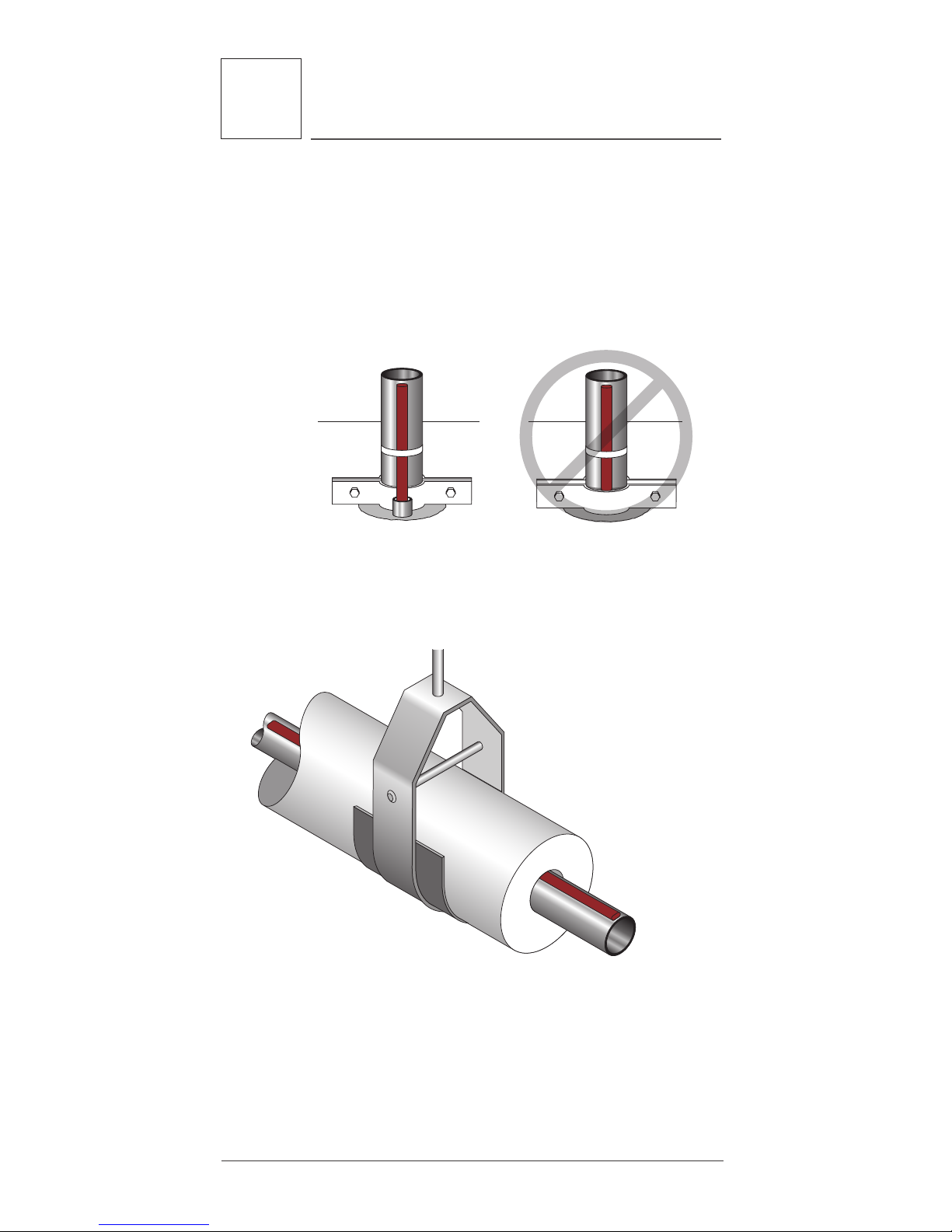
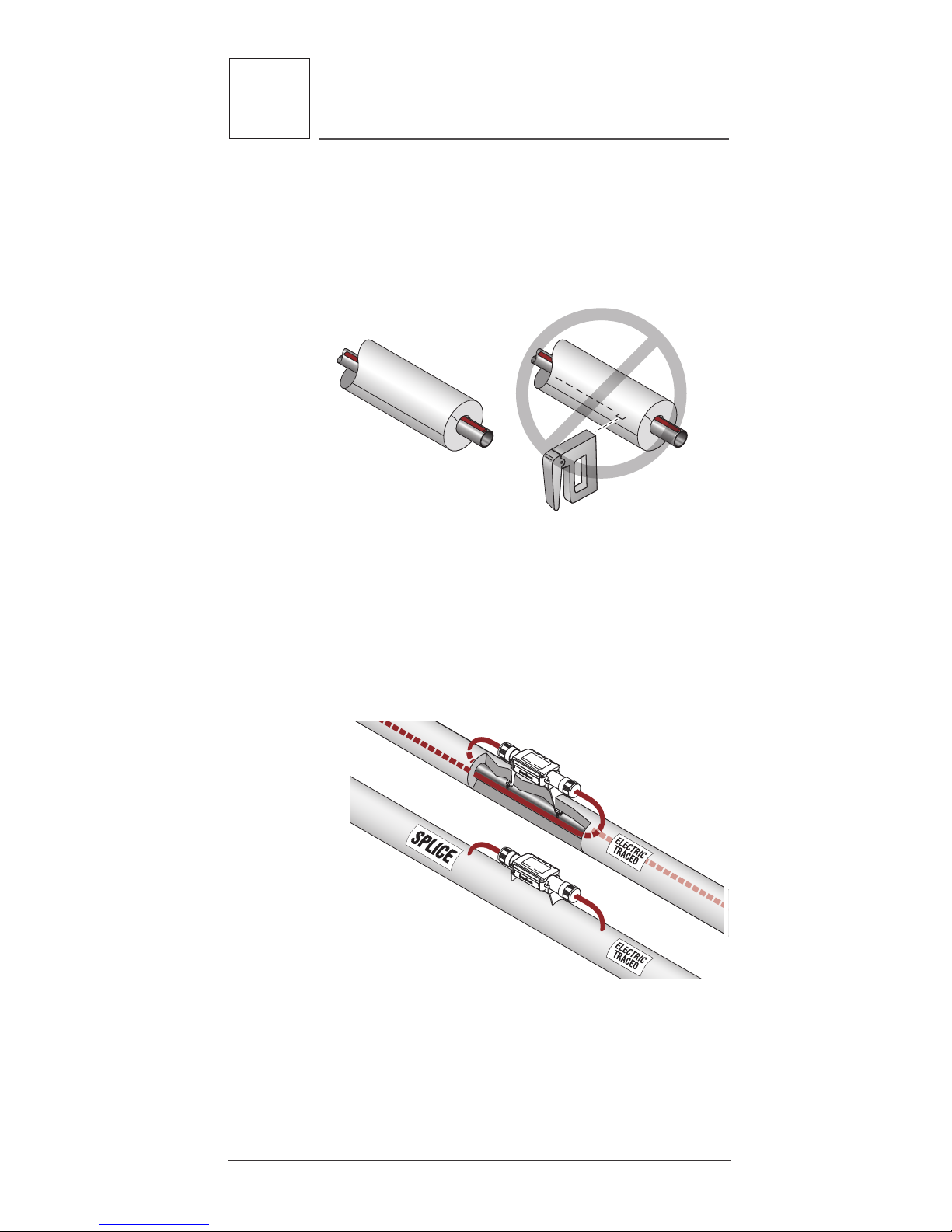
• When installing the heating cable, the cable
must not be compressed or pinched between
two objects. Wall and floor penetrations and pipe
hangers are particular areas of concern.
Figure 3: Protecting the heating cable in floor
penetrations
• Run insulation through the pipe hanger ensuring
that the pipe is not resting on the heater.
Figure 4: Pipe hanger with heating cable
• When making floor or wall penetrations, make
sure the hole is large enough to accommodate
the pipe and the thermal insulation. When sealing
around pipes at floor penetrations, avoid damaging or cutting the heating cable, or pinching it
between the pipe and the concrete.
Page 14
10
3
Heating Cable Installation
Raychem-IM-H57548-HWATsystem-EN 16/08
• The heating cable must not be embedded directly
in the sealing material; the pipe should have thermal insulation over it (if allowed by local codes) or
the heating cable should be run through the penetration in a tube or conduit. If the conduit must be
sealed, use a pliable fire-resistant material (Dow
Corning Fire Stop, 3M Fire Barrier, or T&B FlameSafe) that can be removed if necessary.
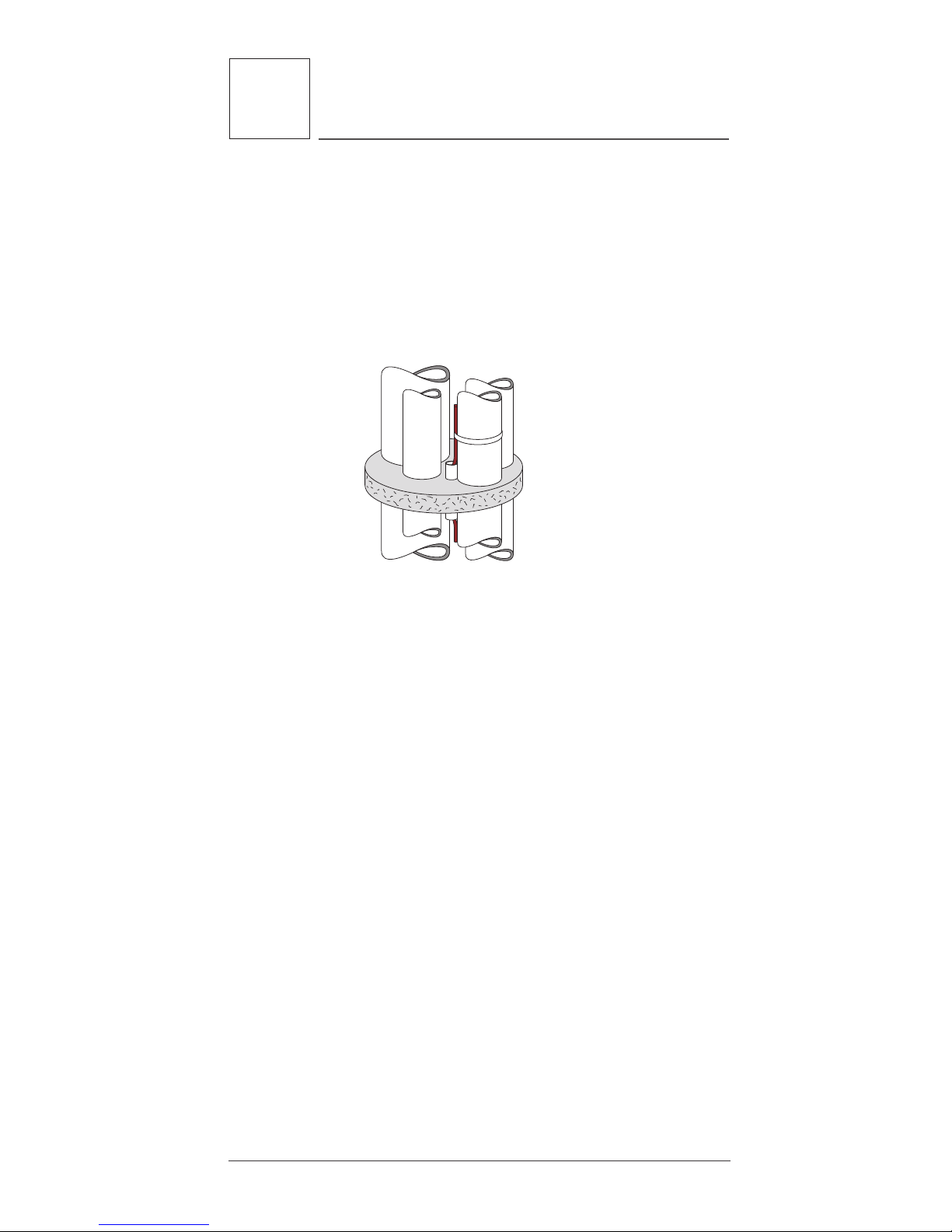
Figure 5: Multiple pipe floor penetration
• On vertical piping groups, run the heating cable
along the inside of the pipe close to other pipes so
it will not be damaged if the pipe hits the side of
the floor penetration. Run the heating cable over
the outside of the pipe support. Do not clamp the
heating cable to the pipe with the pipe support.
• In high-rise construction it may be necessary to
install the HWAT System 10 or 12 floors at a time
to fit into the construction schedule. If so, the
end of the heating cable should be sealed with a
RayClic-E end seal and placed in an accessible
location. This allows testing of one part of the
heating cable at a time, and allows splicing it to
another section when the system is complete.
Paying out the cable:
• Use a reel holder that pays out smoothly with little
tension. If the heating cable snags, stop pulling.
• Keep the heating cable strung loosely but close
to the pipe being traced to avoid interference with
supports and equipment.
• Meter marks on the heating cable can be used to
determine cable length.
Page 15
11
3
Heating Cable Installation
Raychem-IM-H57548-HWATsystem-EN 16/08
• Protect all heating cable ends from moisture, contamination and mechanical damage.
Figure 6: HWAT cable layout
When paying out the heating cable, AVOID:
• Sharp edges
• Excessive pulling force or jerking
• Kinking and crushing
• Walking on it, or running over it with equipment
WARNING: Fire and shock hazard. Do not install
damaged cable. Connection kits and cable ends must
be kept dry before and during installation.
Positioning heating cables
If possible, position the heating cable on the lower
section of the pipe, at the 4 or 8 o’clock positions, as
shown below, to protect it from damage.
Figure 7: Cable positioning
Page 16

12
3
Heating Cable Installation
Raychem-IM-H57548-HWATsystem-EN 16/08
Attaching the heating cable
Starting from the end opposite the reel, tape the
heating cable to the pipe every 2 feet. Work back to
the reel. Leave extra heating cable at the power connection, at all sides of splices and tees to allow for
future servicing. See Table 1 on page15.
• Install heating cable connection kits immediately
after attaching the heating cable. If immediate
installation is not possible, protect the heating
cable ends from moisture.
Bending the cable
When positioning the heating cable on the pipe, do
not bend tighter than 1/2” radius. The heating cable
does not bend easily in the flat plane. Do not force
such a bend, as the heating cable will be damaged.
1/2"
Figure 8: Bending technique
Crossing the cable
HWAT heating cables are self-regulating and may be
overlapped whenever necessary without overheating
or burning out.
Cutting the cable
Cut the heating cable to the desired length after it
is attached to the pipe. HWAT can be cut to length
without affecting the heat output per foot.
Attachment tapes
To ensure that the heating cable is in full contact
with the pipe, use tape to attach the heating cable
to the pipe every 2 ft (.6 m). Use Raychem GT-66
attachment tape. One roll will handle approximately
50 ft (15 m) of cable.
Page 17
13
3
Heating Cable Installation
Raychem-IM-H57548-HWATsystem-EN 16/08
Figure 9: Attaching the heating cable
To ensure sufficient heat transfer AT-180 aluminum
tape must be used to install the heating cable on
plastic pipes as shown in Figure 10.
WARNING: Do not use metal attachments such
as pipe straps or tie wire. Do not use vinyl-based
electrical or duct tape. Use only Pentair Thermal
Management approved tapes.
Raychem HWAT
heating cable
Continuous AT-180
alluminum tape
over heating cable
Rigid plastic pipe
Thermal
insulation
Figure 10: Installed on plastic pipe with aluminum tape
Raychem GT-66 glass tape
2 ft.
Page 18
14
4
Heating Cable Components
Raychem-IM-H57548-HWATsystem-EN 16/08
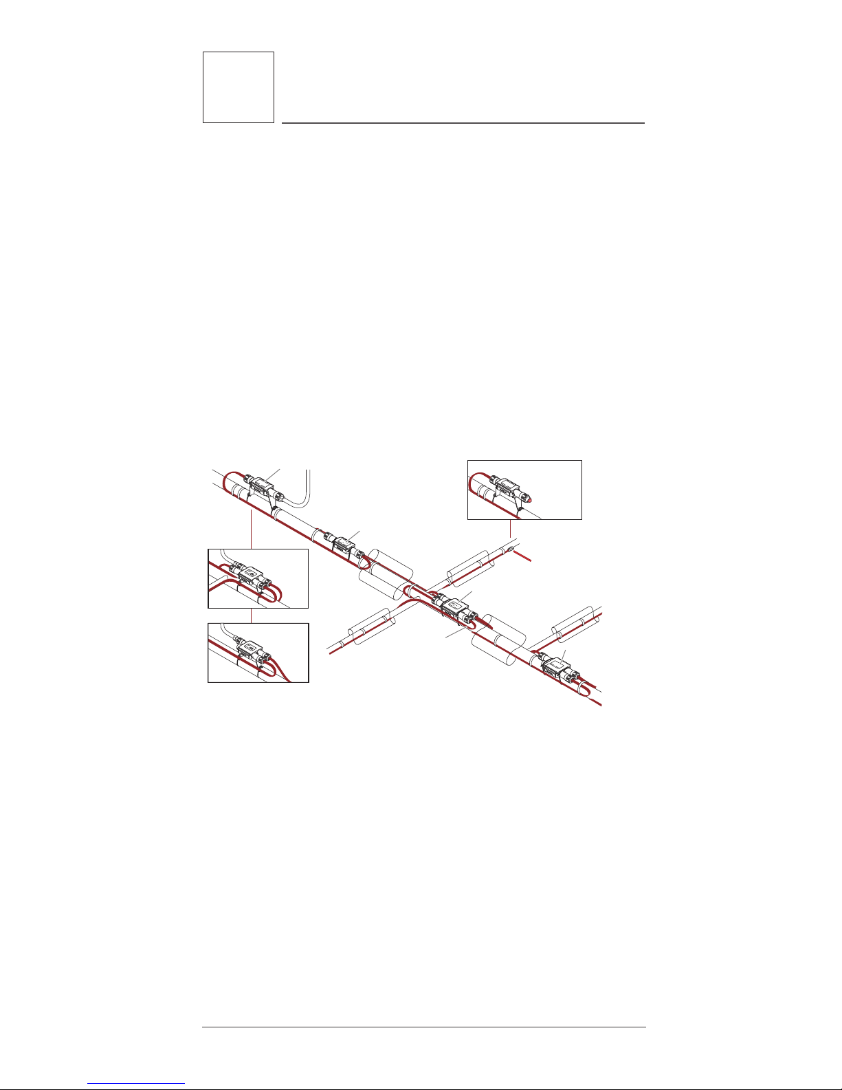
4.1 General Connection Kit Information
Raychem RayClic connection kits must be used with
HWAT-R2 heating cable. A complete circuit requires
a power connection and an end seal. Splices and
tees and other connection kits are used as needed.
Use the HWAT System Design Guide (H57510) to
select appropriate connection kits. Installation
instructions are included with every connection kit.
Steps for preparing the heating cable and installing
connection kits must be followed. HWAT connection
kit locations should be noted on “As Built” drawings.
Connection kit locations should be marked on the
outside of the insulation cladding with the labels
provided in the kits.
RayClic-PT
powered
tee
RayClic-PC
powered connection
RayClic-S
splice
RayClic-X
cross tee
RayClic-T
tee
RayClic-PS
powered
splice
RayClic-LE
lighted end seal
RayClic-E
end seal
Alternate
lighted end seal
Alternate
connection kits
HWAT
heating cable
Figure 11: RayClic connection system
Connection Kit Installation
• When practical, mount the connection kits on top
of the pipe. All heating cable connections must be
mounted above grade level.
• Leave excess cable to serve as a service loop at
all connection kits (power, splice, cross or tee) for
future maintenance, as detailed in Table 1. The
additional heating cable will easily pay for itself in
time savings if it becomes necessary to check or
replace a connection kit after installation. Splices
and tees should have a service loop on each of the
heating cables entering the connection kit.
4 Heating Cable Components
Page 19
15
4
Heating Cable Components
Raychem-IM-H57548-HWATsystem-EN 16/08
TABLE 1: SERVICE LOOPS FOR EACH CONNECTION KIT
RayClic-PC 1 2.0 ft (0.6 m) 2 ft (0.6 m)
RayClic-S 2 1.0 ft (0.3 m) 2 ft (0.6 m)
RayClic-T 3 1.0 ft (0.3 m) 3 ft (0.9 m)
RayClic-X 4 1.0 ft (0.3 m) 4 ft (1.2 m)
RayClic-PS 2 1.5 ft (0.5 m) 3 ft (0.9 m)
RayClic-PT 3 1.3 ft (0.4 m) 4 ft (1.2 m)
RayClic-E 1 NA NA
RayClic-LE 1 2.0 ft (0.6 m) 2.0 ft (0.6m)
Connection # of cable Cable length/ Total cable length
kit name connections/kit connection (Service loop)
• All power connection kits must be installed in
accessible locations. Access to splices, tee kits
and end seals is recommended for future modification or maintenance but is not required.
• Locate junction boxes for easy access but not
where they may be exposed to mechanical abuse.
• Heating cables must be installed over, not under,
pipe straps used to secure components.
WARNING: The black heating cable core is electrically conductive and can short. It must be properly insulated and kept dry. Damaged bus wires can
overheat or short.
WARNING: Fire and shock hazard. Raychem
brand specified components must be used. Do not
substitute parts or use vinyl electrical tape.
Page 20
16
5
Control and Monitoring
Raychem-IM-H57548-HWATsystem-EN 16/08
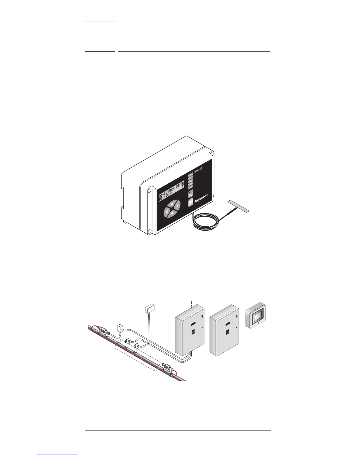
5.1 HWAT-ECO and ACS-30 Controllers
The Raychem HWAT-ECO controller is designed for
use only with HWAT-R2 heating cables and must be
used to ensure proper water temperature.
Refer to the HWAT-ECO Installation and Operation
Manual (H57340) for the installation and operation
instructions of the controller.
Figure 12: HWAT-ECO controller
The ACS-30 Control System is also approved for use
with HWAT-R2 heating cable. Refer to the ACS-30
Programming Guide (H58692) for the installation and
operating instructions of the control system.
Heat-tracing system
ACCS-UIT2
(Optional)
RMM2
COMMON
ALARM
POWER CONTROL
MODULE
ACCS-PCM-5
COMMON
ALARM
POWER CONTROL
MODULE
ACCS-PCM-5
ACCS-PCM2-5 ACCS-PCM2-5
Figure 13: ACS-30 Control System
5 Control and Monitoring
Page 21

17
6
Thermal Insulation
Raychem-IM-H57548-HWATsystem-EN 16/08
6.1 Insulating the System
Pipes must be insulated with the correct thermal
insulation to maintain the desired pipe temperatures. For pipes 1 1/4 inches and smaller, use insulation that is oversized by 1/4 inch to allow room
for insulating over the heating cables. The thermal
insulation schedule is shown in Table 2.
TABLE 2: FIBERGLASS INSULATION SCHEDULE
1/2 3/4 1/2
3/4 1 1
1 1 1/4 1
1 1/4 1 1/2 1 1/2
1 1/2 1 1/2 1 1/2
2 2 2
2 1/2 2 1/2 2 1/2
3 3 3
Copper pipe IPS insulation Insulation
size (in) size (in) thickness (in)
Important: For pipes 3 inches and larger, the
thickness of insulation can be equal to the pipe diameter with one run of heating cable or 1/3 the pipe
diameter with two runs of heating cable.
6.2 Insulation Installation
• Before insulating the pipe, visually inspect the
heating cable and connection kits to ensure they
are properly installed and there are no signs of
damage. Damaged cable or connection kits must
be replaced.
• Check that the insulation type and thickness com-
plies with the insulation schedule detailed in Table
2.
• Insulate the pipes immediately after the heating
cable is installed and has passed all tests to minimize damage to the cable.
• Insulate the pipe at floor and wall penetrations.
Failure to do so will cause cold spots in the water
system and could lead to damage to the heating
cable. If local codes do not allow this, the heating
cable should be run through a conduit or channel
before the firestop is installed. Use a fire-resistant
6 Thermal Insulation
Page 22
18
6
Thermal Insulation
Raychem-IM-H57548-HWATsystem-EN 16/08
sealing compound such as Dow Corning Fire Stop,
3M Fire Barrier, or T&B Flame-Safe.
• Do not use staples to close the insulation. Use
tape or the adhesive-lined edge of the insulation to
ensure that the seam remains sealed. Staples can
damage the HWAT heating cable.
Figure 14: Sealing the insulation seam
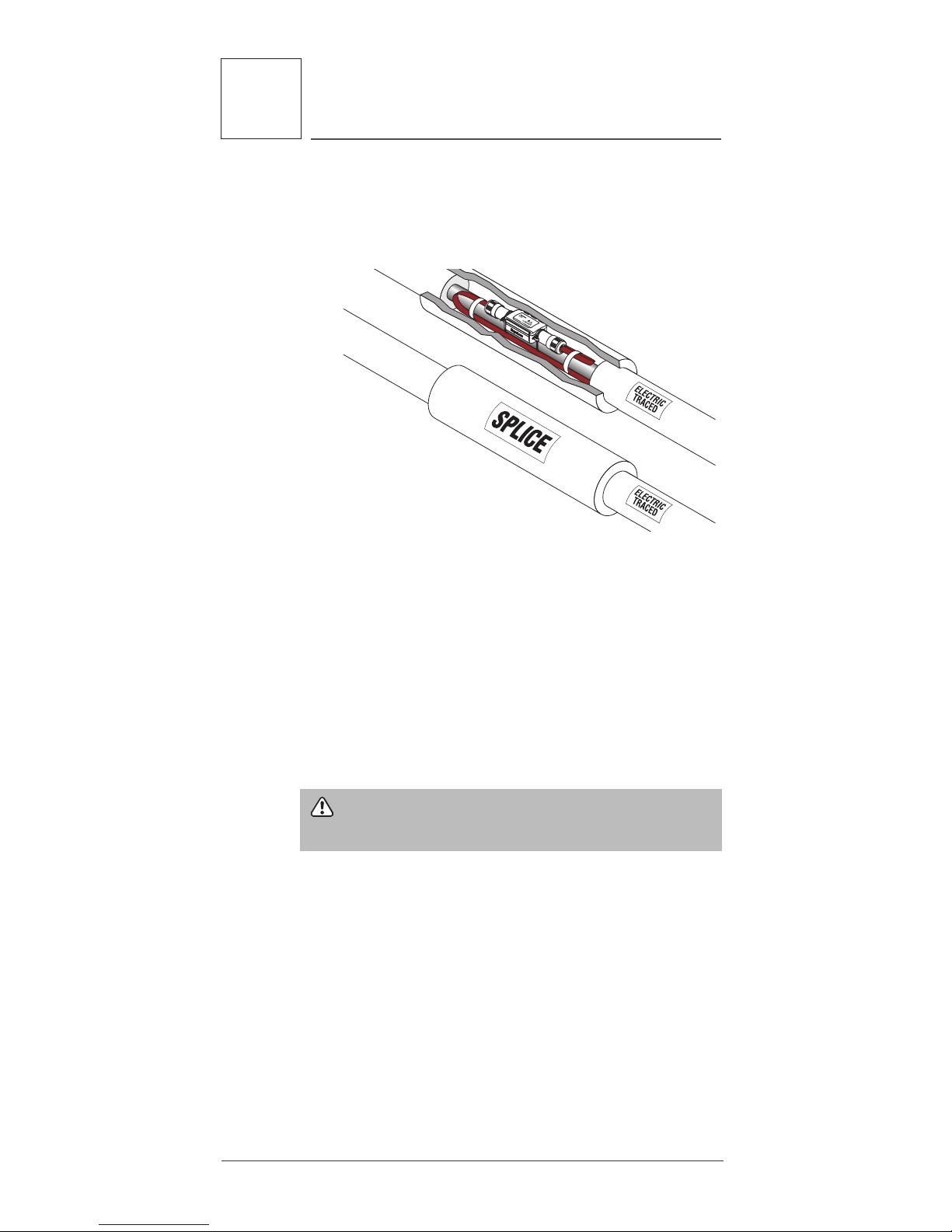
• When installing splice, tee and end seal kits underneath the thermal insulation, mark the location of
splices, tees, and end seals on the outside of the
insulation, with labels provided in the kits, while
installing the insulation. Use large diameter insulation or sheets to cover splices, tees, or service
loops.
Figure 15: Installing Connection kits above insulation.
• All power connection kits must be mounted above
the thermal insulation.
Page 23
19
6
Thermal Insulation
Raychem-IM-H57548-HWATsystem-EN 16/08
• Splice and Tee connection kits may be installed
above the insulation using the optional SB-04
mounting bracket. The pipe and heating cable service loops must be fully insulated as shown above.
Figure 16: Installing connection kits below insulation.
• Make sure that all heat-traced piping, fittings, wall
penetrations, and branch piping are insulated.
Correct temperature maintenance requires properly installed and dry thermal insulation. Uninsulated
sections of pipe can result in cold spots.
• After installing insulation, electrical codes require
that you install “Electric Traced” labels along the
piping at suitable intervals (10-foot intervals recommended) on alternate sides.
WARNING: Use only fire-resistant insulation,
such as fiberglass.
Page 24

20
7
Power Supply and Electrical
Protection
Raychem-IM-H57548-HWATsystem-EN 16/08
7.1 Voltage Rating
Verify that the supply voltage is either 208 or 240
volts as specified by the HWAT System design.
7.2 Circuit Breaker Sizing
Circuit breakers must be sized using the cable
lengths shown in Table 3. Do not exceed the maximum circuit length shown for each breaker size.
When using the HWAT-ECO controller install circuit
breakers that incorporate 30-mA ground-fault circuit
protection, or provide equivalent levels of groundfault protection. Ground-fault protection is integrated into the ACS-30 control system so no additional
protection is required.
TABLE 3: MAXIMUM CIRCUIT LENGTH IN FEET
METERS
15 Amp 250 (75)
20 Amp 330 (100)
30 Amp 500 (150)
Breaker Size HWAT-R2
7.3 Electrical Loading
Over-current devices are selected according to the
heating cable type, supply voltage, and circuit length
to allow for start-up. The design specifies the size
and type of over-current device. Piping systems are
seldom installed exactly as the drawings show. If
changes are made, make sure that all circuit lengths
comply with Table 3.
7 Power Supply and Electrical
Protection
Page 25

21
7
Power Supply and Electrical
Protection
Raychem-IM-H57548-HWATsystem-EN 16/08
7.4 Ground-Fault Protection
If the heating cable is improperly installed, or physically damaged to the point that water contacts the
bus wires, sustained arcing or fire could result.
If arcing does occur, the fault current may be too
low to trip conventional circuit breakers. Pentair
Thermal Management, the U.S. National Electrical
Code, and the Canadian Electrical Code require both
ground-fault protection of equipment and a grounded metallic covering on all heating cables. All HWAT
heating cables meet the metallic covering requirements. Ground-fault protection must be provided by
the installer.
WARNING: To minimize the danger of fire from
sustained electrical arcing if the heating cable is
damaged or improperly installed, and to comply with
Pentair Thermal Management requirements, agency
certifications, and national electrical codes, groundfault equipment protection must be used on each
heating cable branch circuit. Arcing may not be
stopped by conventional circuit breakers.
WARNING: Disconnect all power before making
connections to the heating cable.
Page 26

22
8
Commissioning and Preventive
Maintenance
Raychem-IM-H57548-HWATsystem-EN 16/08
Pentair Thermal Management requires a series of
commissioning tests be performed on the HWAT
System. These tests are also recommended at regular intervals for preventive maintenance. Results
must be recorded and maintained for the life of the
system, utilizing the “Installation and Inspection
Record” (refer to Section 11). Submit this manual
with initial commissioning test results to the owner.
Ensure that your water heater and mixing valve
temperature are set at your desired pipe maintain
temperature.
Important: Exceeding185°F (85°C) for HWAT-R2
will decrease the power output of the heating cables
over time.
8.1 Tests
A brief description of each test is found below.
Detailed test procedures are found in Section 9.
Visual inspection
Visually inspect the pipe, insulation, and connections to the heating cable for physical damage.
Check that no moisture is present, electrical connections are tight and grounded, insulation is dry
and sealed, and control and monitoring systems
are operational and properly set. Damaged heating
cable must be replaced. Once the heating cable is
installed any repairs to pipes should be done very
carefully. The heater must be shielded from excessive heat. Temperatures greater than 185°F will
permanently damage the affected section of heater.
Damage due to excessive external heat may or may
not effect the operation of the entire circuit. A torch
must not be used on the pipe, pipe hangers, or riser
clamps after the heating cable has been installed on
the pipe because this can cause permanent damage to the heating cable (even if it does not appear
to be burned). Use a saw, not a torch, to cut riser
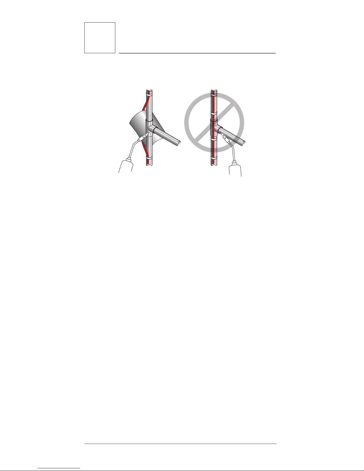
clamps. If use of a torch is unavoidable, cut the
fiberglass tape that holds the HWAT cable to the
pipe on either side of the area to be heated, and pull
the cable away from the pipe. Make sure you do not
cut the HWAT cable. Shield the cable from the flame.
8 Commissioning and Preventive
Maintenance
Page 27
23
8
Commissioning and Preventive
Maintenance
Raychem-IM-H57548-HWATsystem-EN 16/08
Charred or damaged cable must be replaced to avoid
the risk of arcing or fire.
Figure 17: Shielding the cable from the flame
Circuit length verification (capacitance test)
The installed circuit length is verified through a
capacitance measurement of the HWAT heating
cable. Compare the calculated installed length
against the system design. If the calculated length
is shorter than the system design, confirm all connections are secure and the grounding braid is
continuous.
Insulation Resistance
Insulation Resistance (IR) testing is used to verify the
integrity of the heating cable inner and outer jackets.
IR testing is analogous to pressure testing a pipe and
detects if a hole exists in the jacket.
Power check
The power check is used to verify that the system is
generating the correct power output. This test can
be used in commissioning to confirm that the circuit
is functioning correctly. For on-going maintenance,
compare the power output to previous readings.
The heating cable power output per foot is calculated
by dividing the total wattage by the total length of a
circuit. The current, voltage, operation temperature
and length must be known. Circuit length can be
determined from “as built” drawings, meter marks
on the cable or with the capacitance test. The watts
per foot can be compared to the heating cable out-
Page 28

24
8
Commissioning and Preventive
Maintenance
Raychem-IM-H57548-HWATsystem-EN 16/08
put in Section 9 for an indication of heating cable
performance:
Ground-fault test
Test all ground-fault breakers per manufacturer’s
instructions.
Cable and Connection Continuity
Cable and connection continuity test verifies all the
electrical connections are made properly. Pentair
recommends conducing this test as the cable is
installed to identify any potential problems immediately. This test can also be conducted after the
entire cable run is installed but before end seals are
applied.
8.2 Preventative Maintenance
Recommended maintenance for HWAT Systems
consists of performing the system tests for commissioning, and on a regular basis. Procedures for these
tests are described in Section 9. Systems should be
checked each year. If the HWAT System fails any of
the tests, refer to Section 10 for trouble shooting
assistance. Make the necessary repairs and replace
any damaged cable immediately. De-energize all circuits that may be affected by maintenance. Protect
the heating cable from mechanical or thermal damage during maintenance work.
Maintenance records
The “Installation and Inspection Record,” (refer to
Section 11) should be filled out during all maintenance and repairwork and kept for future reference.
Repairs
Use only HWAT heating cable, HWAT-ECO or ACS-30
controller, and RayClic connection kits when replacing any damaged heating cable system. Repair the
thermal insulation to original condition or replace
with new insulation, if damaged. Retest the system
after all repairs or replacements.
WARNING: Damage to cables or components can
cause sustained electrical arcing or fire. Do not
attempt to repair damaged heating cable. Do not
energize cables that have been damaged by fire.
Replace damaged cable at once by removing the
entire damaged section and splicing in a new length
using the appropriate RayClic splice kits.
Page 29

25
9
Test Procedures
Raychem-IM-H57548-HWATsystem-EN 16/08
9.1 System Tests
The following tests must be done after installing
the RayClic connection kits, but before the thermal
insulation is applied to the pipe:
1. Visual inspection
2. Insulation resistance test
After the thermal insulation has been installed on
the pipe, the following tests must be performed:
1. Visual inspection
2. Insulation resistance test
3. Circuit length verification (capacitance test)
4. Power test
5. Temperature test
All test procedures are described in this manual.
It is the installer’s responsibility to perform these
tests or have an electrician perform them. Record
the results in the Installation and Inspection Record
in Section 11.
1. Visual inspection test
• Check inside all power, splice and tee kits for
proper installation, overheating, corrosion, moisture, or loose connections.
• Check the electrical connections to ensure that
ground and bus wires are insulated over their full
length.
• Check for damaged, missing or wet thermal
insulation.
• Check that end seals, splices, and tees are properly labeled on insulation cladding.
• Check HWAT-ECO or ACS-30 controller for proper
setpoint and operation. Refer to the HWAT-ECO
Installation and Operation Manual or ACS-30
Programming Guide for details.
2. Insulation Resistance test
Frequency
Insulation resistance testing is required during the
installation process, and as part of regularly scheduled maintenance, as follows:
9 Test Procedures
Page 30

26
9
Test Procedures
Raychem-IM-H57548-HWATsystem-EN 16/08
• Before installing the cable
• Before installing components
• Before installing the thermal insulation
• After installing the thermal insulation
• Prior to initial start-up (commissioning)
• As part of the regular system inspection
• After any maintenance or repair work
Procedure
Insulation resistance testing (using a megohmmeter) should be conducted at three voltages; 500,
1000, and 2500 Vdc. Potential problems may not be
detected if testing is done only at 500 and 1000 volts.
First measure the resistance between the heating
cable bus wires and the braid (Test A), then measure
the insulation resistance between the braid and the
metal pipe (Test B). Do not allow test leads to touch
junction box, which can cause inaccurate readings.
Important: System tests and regular maintenance
procedures require that insulation resistance testing
be performed. Test directly from the HWAT-ECO, ACS30 or the junction box closest to the RayClic-PC.
WARNING: Fire hazard in hazardous locations.
Insulation resistance test can produce sparks. Be
sure there are no flammable vapors in the area
before performing this test.
Insulation resistance criteria
A clean, dry, properly installed circuit should
measure thousands of megohms, regardless of
the heating cable length or measuring voltage
(500–2500Vdc). The following criteria are provided to
assist in determining the acceptability of an installation where optimum conditions may not apply.
• All insulation resistance values should be greater
than 1000 megohms. If the reading is lower, consult Section 10, Troubleshooting Guide.
Page 31

27
9
Test Procedures
Raychem-IM-H57548-HWATsystem-EN 16/08
Important: Insulation resistance values for Test A
and B for any particular circuit should not vary more
than 25 percent as a function of measuring voltage.
Greater variances may indicate a problem with your
heat-tracing system, confirm proper installation and/
or contact Pentair Thermal Management for assistance.
Figure 18: Insulation resistance test
Test A
L2
L1
Test B
Attach to pipe
Page 32

28
9
Test Procedures
Raychem-IM-H57548-HWATsystem-EN 16/08
Insulation Resistance test procedure
1. De-energize the circuit.
2. Disconnect the HWAT-ECO or ACS-30 controller
if installed.
3. Disconnect bus wires from terminal block.
4. Set test voltage at 0 Vdc.
5. Connect the negative (—) lead to the heating
cable metallic braid or RayClic green wire.
6. Connect the positive (+) lead to both heating cable
bus wires or RayClic black wires.
7. Turn on the megohmmeter and set the voltage
to 500 Vdc; apply the voltage for 1 minute. Meter
needle should stop moving. Rapid deflection indicates a short. Record the insulation resistance
value in the Inspection Record.
8. Repeat Steps 4–7 at 1000 and 2500 Vdc.
9. Turn off the megohmmeter.
10. If the megohmmeter does not self-discharge,
discharge phase connection to ground with
a suitable grounding rod. Disconnect the
megohmmeter.
11. Repeat this test between braid and pipe.
12. Reconnect bus wires to terminal block.
13. Reconnect the HWAT-ECO controller.
3. Circuit length verification (capacitance test)
Connect the capacitance meter negative lead to both
bus wires and the positive lead to the braid wire. Set
the meter to the 200nF range. Multiply this reading
by the Capacitance factor for the correct heating
cable shown below to determine the total circuit
length.
Length (ft or m) = Capacitance (nF) x Capacitance
factor (ft or m/nf)
Page 33

29
9
Test Procedures
Raychem-IM-H57548-HWATsystem-EN 16/08
TABLE 4: CAPACITANCE FACTORS
HWAT-R2 5.8 1.8
Heating Cable Capacitance Factor
ft/nF m/nF
Compare the calculated circuit length to the design
drawings and circuit breaker sizing tables.
Figure 19: Capacitance test
4. Power check
The power output of self-regulating heating cable
is temperature-sensitive and requires the following
special procedure to determine its value:
Important: Run hot water through the piping system before powering the HWAT-R2 heating cable. This
will ensure the system is at a uniform pipe temperature. Dot not power the system when the pipe temperature is below 50F(10C).
1. Power the heating cable and allow it to stabilize
for 2 hours, then measure current and voltage at
the junction box. If a controller is used, refer to
details below.
2. Measure the pipe temperature under the thermal
insulation at several locations.
3. Calculate the power of the heating cable by mul-
tiplying the current by the input voltage and dividing by the actual circuit length.
Power (w/ft or m) =
Volts (Vac) x Current (A)
Length (ft or m)
The power calculated should be similar to the value
generated by:
Rated Power (w/ft or m) = Volts (Vac) x Rated
Current
Page 34

30
9
Test Procedures
Raychem-IM-H57548-HWATsystem-EN 16/08
TABLE 5: RATED CURRENT A/FT OR M
HWAT-R2 140˚F (60˚C) .017 (.056)
Heating Pipe Rated Current
Cable Temperature (A/ft or m)
5. Temperature test
When testing an HWAT System for temperatures it is
important to test in an appropriate sequence. Testing
should start at the point of use closest to the water
heater and progress out.
Testing should be done after a minimum of 4 hours
of no water usage. This will ensure that the temperatures indicated are not due to flow conditions.
It is a good idea to turn off all cold water valves to
eliminate the possibility of introducing cold water to
the hot side via a cross connection.
The following example illustrates a typical temperature test sequence for an HWAT System.
2
3
1
5
4
9
8
7
10
6
11
Figure 20: Typical temperature test sequence
Page 35

31
9
Test Procedures
Raychem-IM-H57548-HWATsystem-EN 16/08
9.2 Fault Location Tests
There are three methods used for finding a fault
within a section of heating cable:
1. Ratio method
2. Conductance method
3. Capacitance method
1. Ratio method
The ratio method uses resistance measurements
taken at each end of the heating cable to approximate the location of a bus wire short. A shorted
heating cable could result in a tripped circuit breaker. If the resistance can be read on a standard ohm
meter this method can also be used to find a fault
from a bus wire to the ground braid. This type of
short would trip a GFPD and show a failed reading.
Measure the bus-to-bus heating cable resistance at
each end (measurement A and measurement B) of
the suspected section.
A B
A
B
A B
Braid
Figure 21: Cable resistance measurement test
The approximate location of the fault, expressed as a
percentage of the heating cable length from the front
end, is:
Fault location:
D =
A
x 100
(A + B)
Example: A = 1.2 ohms
B = 1.8 ohms
Fault location: D = 1.2 / (1.2 + 1.8) x 100
= 40%
The fault is located 40% into the circuit as measured from the front end.
To locate a low resistance ground fault, measure
between bus and braid.
Page 36

32
9
Test Procedures
Raychem-IM-H57548-HWATsystem-EN 16/08
A B
A
B
Braid
Figure 22: Low resistance ground-fault test
The approximate location of the fault, expressed as a
percentage of the heating cable length from the front
end is:
Fault location:
D =
A
x 100
(A + B)
Example: A = 1.2 ohms
B = 1.8 ohms
Fault location: D = 1.2 / (1.2 + 1.8) x 100
= 40%
The fault is located 40% into the circuit as measured from the front end
2. Conductance method
The conductance method uses the core resistance
of the heating cable to approximate the location of a
fault when the heating cable has been severed and
the bus wires have not been shorted together. A severed cable may result in a cold section of pipe and
may not trip the circuit breaker.
Measure the bus-to-bus heating cable resistance at
each end (measurement A and measurement B) of
the suspect section. Since self-regulating cables are
a parallel resistance, the ratio calculations must be
made using the conductance of the cable.
A B
Figure 23: Cable resistance measurement
Page 37

33
9
Test Procedures
Raychem-IM-H57548-HWATsystem-EN 16/08
The approximate location of the fault, expressed as a
percentage of the heating cable length from the front
end, is:
Fault location:
D =
1/ A
x 100
(1/A + 1/B)
Example: A = 100 ohms
B = 25 ohms
Fault location: D = (1/100) / (1/100 + 1/25) x 100
= 20%
The fault is located 20% from the front end of the
circuit.
3. Capacitance method
This method uses capacitance measurement (nF) as
described in "3. Circuit length verification (capacitance test)" on page28, to approximate the location of a fault where the heating cable has been severed, or a connection kit has not been connected.
Record the capacitance reading from one end of the
heating cable. The capacitance reading should be
measured between both bus wires twisted together
(positive lead) and the braid (negative lead). Multiply
the measured capacitance with the heating cable’s
capacitance factor as listed in the following example:
Example: HWAT-R2 = 16.2 nF
Capacitance factor = 5.8 ft/nF
Fault location = 42.2 nF x 5.8 ft/nF = 245 ft (75 m)
from reading location
As an alternative, capacitance values from each
end. The ratio of one capacitance value taken from
one end (A) divided by the sum of both A and B (A
+ B) and then multiplied by 100 yields the distance
from the first end, expressed as a percentage of the
total heating cable circuit length. See Table 4 on
page29, for capacitance factors.
Fault location:
C =
A
x 100
(A + B)
Page 38

34
9
Test Procedures
Raychem-IM-H57548-HWATsystem-EN 16/08
9.3 Cable and Connection Continuity Test:
To complete a continuity test it is best to start the
installation with a power connection kit. A completed power connection kit allows for easier testing.
The bus wires and braid can be temporarily connected together at the power connection end (Figure
24) and resistance can be tested at the other end as
each additional component is added to the system.
Procedure:
1. De-energize the circuit
2. Disconnect cable bus wires and ground wire
3. Temporarily connect cable bus wires and ground
wire together with a wire nut (Figure 24)
Figure 24:
4. Go to the end of the heating cable run and measure resistance using an ohm meter.
5. A resistance reading should be taken for
each bus wire to braid and then bus wire to
bus wire. Braid to A should equal Braid to
B, A to B will be slightly higher. (Figure 25)
Figure 25:
Page 39

35
9
Test Procedures
Raychem-IM-H57548-HWATsystem-EN 16/08
6. If a higher reading is measured on one of the tests
all connections are not completed and there is not
continuity for one or both of the bus wires.
7. If resistance values of braid to A and braid to B are
not within 20% of each other inspect all connection kits (splice, tee, and cross) between the power
connection and the cable end that is being tested.
8. If resistance values of braid to A and braid to B are
within 20% of each other the cable continuity is
intact. Continue with system installation.
9. Repeat test procedures for all branch lines to
verify entire heat tracing circuit.
10. After entire circuit passes continuity test, remove
wire nut on power connection kit and connect to
heat trace controller.
Note: Readings can be taken at a previously
installed RayClic power, splice, tee or cross connection by using the test ports available inside the
component (see figure 26). Testing at a RayClic will
only confirm continuity to the previous components;
it will not verify continuity to the cable end seal.
Figure 26:
Page 40

36
10
Troubleshooting Guide
Raychem-IM-H57548-HWATsystem-EN 16/08
Symptom Probable Causes
Corrective Action
Low water temperature
Insulation is wet, or missing.
HWAT-ECO controller lowered the pipe
setpoint temperature because water heater is
cold.
Ambient too low.
Improper voltage applied.
Improper insulation thickness used.
HWAT-ECO or ACS-30 was set incorrectly.
Cold water is being introduced into the hot
water system.
Tripped circuit breaker
Remove wet insulation and replace with dry insulation, and secure it
with proper weatherproofing.
Verify the HWAT-ECO water heater setting, water heater
temperature, and sensor placement; and correct as required.
Set the HWAT-ECO or ACS-30 to the appropriate ambient
temperature.
Refer to the HWAT-ECO Installation and Operation Manual (H57340)
to set the HWAT-ECO to the correct voltage (208 or 240 Vac)
Contact your Pentair Thermal Management representative to
confirm the design and modify as recommended.
Refer to the HWAT-ECO Installation and Operation Manual (H57340)
or ACS-30 Programming Guide (H58692) for the correct settings.
Verify that the plumbing fixtures and valves are operating properly.
See "Circuit breaker trips" section of this Troubleshooting Guide.
Symptom Probable Causes
Corrective Action
Low or no power output Low or no input voltage applied.
The circuit is shorter than the design
shows, due to splices or tees not being
connected, or the heating cable having
been severed.
Improper component connection
causing a high-resistance connection.
HWAT-ECO or ACS-30 set wrong or
incorrectly wired.
The heating cable has been exposed to
excessive temperature, moisture or
chemicals.
Repair the electrical supply lines and equipment.
Check the routing and length of heating cable (use “as built”
drawings to reference actual pipe layout). Connect all splices or
tees. Locate and replace any damaged heating cables. Then
recheck the power output.
Examine RayClic connection kits for proper installation. Check for
loose wiring connections and rewire if necessary.
Refer to the HWAT-ECO Installation and Operation Manual
(H57340) or ACS-30 Programming Guide (H58692) for the correct
settings.
Check the pipe temperature. Verify heater selection. Check the
power output of the heating cable per the design vs. actual.
Reduce pipe temperature if possible or contact your Pentair
Thermal Management representative to confirm design.
Replace damaged heating cable. Check the pipe temperature.
Check the power output of heating cable.
10 Test Procedures
Page 41

37
10
Troubleshooting Guide
Raychem-IM-H57548-HWATsystem-EN 16/08
Corrective Action
Remove wet insulation and replace with dry insulation, and secure it
with proper weatherproofing.
Verify the HWAT-ECO water heater setting, water heater
temperature, and sensor placement; and correct as required.
Set the HWAT-ECO or ACS-30 to the appropriate ambient
temperature.
Refer to the HWAT-ECO Installation and Operation Manual (H57340)
to set the HWAT-ECO to the correct voltage (208 or 240 Vac)
Contact your Pentair Thermal Management representative to
confirm the design and modify as recommended.
Refer to the HWAT-ECO Installation and Operation Manual (H57340)
or ACS-30 Programming Guide (H58692) for the correct settings.
Verify that the plumbing fixtures and valves are operating properly.
See "Circuit breaker trips" section of this Troubleshooting Guide.
Corrective Action
Repair the electrical supply lines and equipment.
Check the routing and length of heating cable (use “as built”
drawings to reference actual pipe layout). Connect all splices or
tees. Locate and replace any damaged heating cables. Then
recheck the power output.
Examine RayClic connection kits for proper installation. Check for
loose wiring connections and rewire if necessary.
Refer to the HWAT-ECO Installation and Operation Manual
(H57340) or ACS-30 Programming Guide (H58692) for the correct
settings.
Check the pipe temperature. Verify heater selection. Check the
power output of the heating cable per the design vs. actual.
Reduce pipe temperature if possible or contact your Pentair
Thermal Management representative to confirm design.
Replace damaged heating cable. Check the pipe temperature.
Check the power output of heating cable.
Page 42

38
10
Troubleshooting Guide
Raychem-IM-H57548-HWATsystem-EN 16/08
Symptom Probable Causes
Corrective Action
Low or inconsistent
insulation resistance
Nicks or cuts in the heating cable.
Short between the braid and heating cable
core or the braid and pipe.
Arcing due to damaged heating-cable
insulation.
Moisture present in the components.
Test leads touching the junction box.
If heating cable is not yet insulated, visually inspect the entire
length for damage, especially at elbows and flanges and around
valves. If the system is insulated, remove the connection kits
one-by-one to isolate the damaged the section.
Replace damaged heating-cable sections.
If moisture is present, dry out the connections and retest. Be sure
all conduit entries are sealed, and that condensate in conduit
cannot enter power connection boxes. If heating-cable core or bus
wires are exposed to large quantities of water, replace the heating
cable. (Drying the heating cable is not sufficient, as the power
output of the heating cable can be significantly reduced.)
Clear the test leads from junction box and restart.
Symptom Probable Causes
Corrective Action
Circuit breaker trips
Circuit breaker is undersized.
Connections and/or splices are shorting out.
Physical damage to heating cable is causing
a direct short.
Bus wires are shorted at the end.
Circuit lengths too long
Nick or cut exists in heating cable or power
feed wire with moisture present or moisture
in connections.
GFPD is undersized (5 mA used instead of
30 mA) or miswired.
Recheck the design for startup temperature and current loads. Do not
exceed the maximum circuit length for heating cable used. Replace
the circuit breaker, if defective or improperly sized.
Visually inspect the RayClic connection systems. Replace if necessary.
Check for damage around the valves and any area where there may
have been maintenance work. Replace damaged sections of heating
cable.
Check the end seal to ensure that bus wires are not shorted. If a dead
short is found, the heating cable may have been permanently damaged
by excessive current and may need to be replaced.
Separate the circuit into multiple circuits that do not exceed max
circuit lengths.
Replace the heating cable, as necessary. Dry out and reseal the
connections and splices. Using a megohmmeter, retest insulation
resistance.
Replace undersized GFPD with 30 mA GFPD. Check the GFPD wiring
instructions.
Page 43

39
10
Troubleshooting Guide
Raychem-IM-H57548-HWATsystem-EN 16/08
Corrective Action
If heating cable is not yet insulated, visually inspect the entire
length for damage, especially at elbows and flanges and around
valves. If the system is insulated, remove the connection kits
one-by-one to isolate the damaged the section.
Replace damaged heating-cable sections.
If moisture is present, dry out the connections and retest. Be sure
all conduit entries are sealed, and that condensate in conduit
cannot enter power connection boxes. If heating-cable core or bus
wires are exposed to large quantities of water, replace the heating
cable. (Drying the heating cable is not sufficient, as the power
output of the heating cable can be significantly reduced.)
Clear the test leads from junction box and restart.
Corrective Action
Recheck the design for startup temperature and current loads. Do not
exceed the maximum circuit length for heating cable used. Replace
the circuit breaker, if defective or improperly sized.
Visually inspect the RayClic connection systems. Replace if necessary.
Check for damage around the valves and any area where there may
have been maintenance work. Replace damaged sections of heating
cable.
Check the end seal to ensure that bus wires are not shorted. If a dead
short is found, the heating cable may have been permanently damaged
by excessive current and may need to be replaced.
Separate the circuit into multiple circuits that do not exceed max
circuit lengths.
Replace the heating cable, as necessary. Dry out and reseal the
connections and splices. Using a megohmmeter, retest insulation
resistance.
Replace undersized GFPD with 30 mA GFPD. Check the GFPD wiring
instructions.
Page 44

40
11
Troubleshooting Guide
Raychem-IM-H57548-HWATsystem-EN 16/08
Pentair Thermal Management Industrial Heat-Tracing Installation and Inspection Record
Test Date:_________
Facility: (Circuit Number)
Commission Inspection date:
Inspected by (Name):
Panel and Circuit Breaker Number:
Water heater/mixing valve temperature setting (°F)
Designed circuit length (ft):
Capacitance test
nF:
Cap factor (Table 4):
nF X Cap Factor= (ft/m)
HWAT-ECO setting:
Heating cable type:
Voltage:
Ambient Temp:
Set point: Maintain
Power factor
Test Date:
Visual Inspection
Confirm 30-mA ground-fault device (proper rating/function)
Confirm all electrical connections in the RayClic and HWAT-ECO are tight
and wires secure.
Visual inspection inside connection boxes for overheating, corrosion,
moisture, loose connections and other problems.
Proper electrical connection, ground, and bus wires insulated over
full length.
Correct thermal insulation used for each pipe size (Reference Table 2)
Damaged or missing thermal insulation for the entire hot water piping system.
Covered end seals, splices, and tees properly labeled on insulation.
Check HWAT-ECO for moisture, corrosion, setpoint, switch operation
Insulation resistance test
Bus to braid (Test A) 500 Vdc
1000 Vdc
2500 Vdc
Braid to pipe (Test B) 500 Vdc
1000 Vdc
2500 Vdc
Power and temperature check
Panel voltage (V)
Circuit voltage (V)
Circuit end (V)
Circuit amps after 2 hours (A)
Pipe temperature (°F)
megohm megohm megohm megohm
11 Troubleshooting Guide
Page 45

41
11
Troubleshooting Guide
Raychem-IM-H57548-HWATsystem-EN 16/08
Test Date:_________
megohm megohm megohm megohm
Page 46

42
Raychem-IM-H57548-HWATsystem-EN 16/08
Page 47

43
Raychem-IM-H57548-HWATsystem-EN 16/08
Page 48

WWW.THERMAL.PENTAIR.COM
NORTH AMERICA
Tel: +1.800.545.6258
Fax: +1.800.527.5703
Tel: +1.650.216.1526
Fax: +1.650.474.7711
thermal.info@pentair.com
EUROPE, MIDDLE EAST, AFRICA
Tel: +32.16.213.511
Fax: +32.16.213.603
thermal.info@pentair.com
ASIA PACIFIC
Tel: +86.21.2412.1688
Fax: +86.21.5426.2917
cn.thermal.info@pentair.com
LATIN AMERICA
Tel: +1.713.868.4800
Fax: +1.713.868.2333
thermal.info@pentair.com
Pentair, RayClic, and HWAT are owned by Pentair or its global affiliates. All other trademarks are the property of their respective owners.
Pentair reserves the right to change specifications without prior notice.
© 2004–2016 Pentair. P000000272
THERMAL MANAGEMENT SOLUTIONS Raychem-IM-H57548-HWATsystem-EN 16/08
Page 49

HWAT-ECO
INSTALLATION AND OPERATION MANUAL FOR
HOT WATER TEMPERATURE MAINTENANCE SYSTEM
ELECTRONIC CONTROLLER
THERMAL MANAGEMENT SOLUTIONS WWW.THERMAL.PENTAIR.COM
Page 50

ii
EN-RaychemHWATECOcontroller-IM-H57340 03/13
Important Safeguards and Warnings
WARNING: FIRE AND SHOCK HAZARD
Raychem HWAT Systems must be installed correctly to ensure proper
operation and to prevent shock and fire. Read these important warnings and carefully follow all the installation instructions.
• To minimize the danger of fire from sustained electrical arcing if
the heating cable is damaged or improperly installed, and to comply
with Pentair Thermal Management requirements, agency certifications, and national electrical codes, ground-fault equipment protection must be used on each heating cable branch circuit. Arcing may
not be stopped by conventional circuit breakers.
• Approvals and performance are based on the use of Pentair
Thermal Management parts only. Do not substitute parts or use
vinyl electrical tape.
• Bus wires will short if they contact each other. Keep bus wires
separated.
• Connection kits and heating cable ends must be kept dry before and
during installation.
• The black heating cable core is conductive and can short. They must
be properly insulated and kept dry.
• Damaged bus wires can overheat or short. Do not break bus wire
strands when preparing the cable for connection.
• Damaged heating cable can cause electrical arcing or fire. Do not
use metal attachments such as pipe straps or tie wire. Use only
Pentair Thermal Management approved tapes and cable ties to
secure the cable to the pipe.
• Do not attempt to repair or energize damaged cable. Remove
damaged cable at once and replace with a new length using the
Raychem RayClic-S splice kit. Replace damaged connection kits.
• Use only fire-resistant insulation which is
compatible with the application and the maximum exposure
temperature of the system to be traced.
Page 51

iii
EN-RaychemHWATECOcontroller-IM-H57340 03/13
Table of Contents
1
General Information 1
1.1 Use of the Manual 1
1.2 Features 1
1.3 Technical Data 3
1.4 Care and Maintenance 7
1.5 HWAT Heating Cables 7
2
Installation 9
2.1 Installing the Controller 9
2.2 Wiring the Controller 13
3
Programming the Controller 26
3.1 Programming Overview 26
3.2 Initializing the Controller 27
3.3 Advanced Programming 33
4
Error/Alarms and Troubleshooting 45
5
Pre-Defined Programs 50
6
Heat-Up Cycle Graphs 52
7
Cool-Down Graph 54
Page 52

iv
EN-RaychemHWATECOcontroller-IM-H57340 03/13
A
F
B
C
D
E
Item Qty Description
A 1 HWAT-ECO controller
B 1 Temperature sensor with 13 ft (4 m) cable
C 2 Mounting screws
D 2 Mounting washers
E 1 Aluminum tape
F 1 Manual
HWAT-ECO
INSTALLATION AND OPERATION MANUAL FOR
HOT WATER TEMPERATURE MAINTENANCE SYSTEM
ELECTRONIC CONTROLLER
THERMAL MANAGEMENT SOLUTIONS WWW.THERMAL.PENTAIR.COM
Figure 1: Kit contents
Page 53

v
EN-RaychemHWATECOcontroller-IM-H57340 03/13
Power supply (green LED)
Power to heating cable (green LED)
Heat-up cycle (green LED) - increased risk of scalding
Pipe Temperature alarm (requires installed sensor) (green LED)
Alarm (red LED)
Escape, backspace; NO; or display maintain temperature setpoint
Arrow keys: to change menu selection or position the cursor
Confirm selection, new value or YES
6.5"
(165 mm)
2 ea - 1/2" conduit
entries
To water heater sensor
To HWAT-ECO network/alarm
entries
3.4"
(85 mm)
A
B
C
D
E
F
G
H
A
B
C
D
E
F
G
H
Figure 2: HWAT-ECO controller
Page 54

vi
EN-RaychemHWATECOcontroller-IM-H57340 03/13
Page 55

1
General Information
1
EN-RaychemHWATECOcontroller-IM-H57340 03/13
1.1 Use of the Manual
This manual covers the installation and operation of
the HWAT-ECO controller and must be used with the
following additional documents:
• HWAT System Product and Selection Design Guide
(H57538)
• HWAT System Installation and Operation Manual
(H57548)
Important: For the Pentair Thermal Management
warranty and agency approvals to apply, the instructions included in this manual and product packages
must be followed.
1.2 Features
The Raychem HWAT-ECO controller is designed
for operation with HWAT-Y2 and HWAT-R2 selfregulating heating cables. The HWAT-ECO controller
provides the following features:
• Flexible temperature control of hot water tem-
perature maintenance systems.
• Integrated function that lowers the maintain tem-
perature during low use hours to save energy.
• Heat-Up cycle function that increases the water
temperature in a stagnant pipe.
Page 56

1
General Information
2
EN-RaychemHWATECOcontroller-IM-H57340 03/13
• Building Management System (BMS) interface
that receives a DC voltage to set the maintain
temperature.
• Alarm relay to signal power, temperature, or
communication problems.
• Pipe temperature monitoring, low temperature
alarm and high temperature cut-out.
• Master/slave function that allows one HWAT-ECO
to control up to eight additional HWAT-ECO
controllers.
• 9 pre-defined programs that can be customized by
the user.
Page 57

1
General Information
3
EN-RaychemHWATECOcontroller-IM-H57340 03/13
1.3 Technical Data
Use Only for HWAT-Y2 and
HWAT-R2 heating cables
Maintain temperature
setpoint
105˚F (40˚C) to 140˚F
(60˚C)
Hot water piping
ambient temperature
60˚F (15˚C) to 80˚F (25˚C)
Controller ambient
temperature
40˚F (5˚C) to 105˚F (40˚C)
ambient
Switching capacity 24 A 208/240 Vac max.
Operating voltage 208/240 (±10%), 60 Hz
Internal power
consumption
2.5 W
Circuit protection
(not provided with
HWAT-ECO controller)
Max. 30 A with 30 mA
ground-fault protection
Power terminal block 16–10 AWG (1.5–4 mm2)
Use copper conductors
only
Internal temperature
alarm
150˚F (65˚C)
BMS control voltage 0–10 Vdc
BMS cable maximum
length
328 ft (100 m)
Page 58

1
General Information
4
EN-RaychemHWATECOcontroller-IM-H57340 03/13
Alarm contacts Max. 24 Vdc or 24 Vac, 1A,
SPST, voltage free,
NO/NC
Alarm events • Loss of power
• Controller reinitialized
• Internal controller
temperature too high
• Lost date and time
settings
• Internal failure
• Pipe temperature too
high (optional)
• Pipe heater temperature too low (optional)
• Network error
Power correction factor To increase or decrease
your actual pipe maintain
temperature or adjust for
plastic pipe.
Pipe temperature sensor Thermistor with 13 ft
(4m) lead provided. A
PT100 RTD may be optionally used. Max length is
328 ft (100 m)
Page 59

1
General Information
5
EN-RaychemHWATECOcontroller-IM-H57340 03/13
Electromagnetic Complies to EN 5014-1
Compatibility (EMC) for
emission and 60730-1 for
immunity
Real time clock Leap year correction
Clock accuracy ±10 minutes per year
Enclosure rating NEMA 12 (IP54) – indoor
use only
Enclosure material ABS
Mounting Wall mount with two
screws or optional DIN rail
Conduit entries 2 ea – 1/2 in conduit entries
Cable gland 3-hole grommet
Maximum cable size:
• 2-wire: 20 AWG (0.5 mm2)
• 4-wire: 24 AWG (0.2 mm2)
Default programs 9 pre-defined programs
that can be customized
by user
Program settings 48 1/2-hour time blocks
of the following program
settings: Off, Economy,
Maintain and Heat-Up
cycle
Page 60

1
General Information
6
EN-RaychemHWATECOcontroller-IM-H57340 03/13
Password 4-digit password protection
Master/slave Master is selectable in the
controller, up to 8 slaves
can be connected
Master/slave cable 2-wire, min. 24 AWG
(0.2 mm2) twisted pair and
insulation of 300 V, Max
length cable is 100 m
Parameters in memory All parameters are stored
in nonvolatile memory,
except time and date
Clock backup time Rechargable Lithium bat-
tery. Battery will retain
time and date for up to 30
days when power is lost
Approvals
80BJ
Type 12
Energy Management Equipment
(for use with HWAT-R2 and HWAT-Y2 heating cables only.)
Weight 2 lbs (1 kg)
Size 6.5 in x 3.4 in x 2.8 in
(165 mm x 85 mm x
71 mm)
Page 61

1
General Information
7
EN-RaychemHWATECOcontroller-IM-H57340 03/13
1.4 Care and Maintenance
To clean the HWAT-ECO use a damp cloth. Do not
use solvents. Do not pour water directly on the
device. Do not use a water hose or high pressure
cleaner.
Important: In case of questions or product failure,
please contact your Pentair Thermal Management representative, or call Pentair Thermal Management at
800-545-6258.
1.5 HWAT Heating Cables
Maintain temperature
Depending on the ambient temperature and voltage,
HWAT-Y2 is designed to maintain temperatures up to
125˚F (52˚C), and HWAT-R2 is designed to maintain
temperatures up to 140˚F (60˚C).
Installing the heating cables
Install the HWAT heating cable system as instructed
in the HWAT System Installation and Operation
Manual (H57548). The controller must be installed by
a professional electrical installer familiar with electrical safety codes and practices.
Page 62

1
General Information
8
EN-RaychemHWATECOcontroller-IM-H57340 03/13
Ground-fault protection
WARNING: To minimize the danger of fire from
sustained electrical arcing if the heating cable is
damaged or improperly installed, and to comply with
the requirements of approvals agencies, Pentair
Thermal Management and national electrical codes,
ground-fault equipment protection must be used on
each heating cable branch circuit. Arcing may not be
stopped by conventional circuit protection. The
HWAT-ECO does not include ground-fault protection.
Pre-Installation testing
Prior to installing the HWAT-ECO controller, perform
the insulation resistance (Megger) test and circuit
length verification (Capacitance) test on the heating
cable as detailed in the HWAT System Installation
and Operation Manual (H57548).
Page 63

2
Installation
9
EN-RaychemHWATECOcontroller-IM-H57340 03/13
2.1 Installing the Controller
Install the controller in an indoor, dry, clean, accessible location. If using the optional pipe temperature
sensor, make sure you install the controller within
328 ft (100 m) of where you want to monitor the pipe
temperature.
Opening the controller
WARNING: To prevent shock, always switch off
the power supply (circuit breaker) before opening the
controller.
The HWAT-ECO has a removable front cover. Both
the cover and the box have electronic parts and are
connected to each other by a 14-pin connector. First
unscrew the four screws in the cover. Carefully pull
the cover straight out, not sideways!
Page 64

2
Installation
10
EN-RaychemHWATECOcontroller-IM-H57340 03/13
Figure 3: Opening the controller
Wall mounting the controller
Mount the controller using either of the options
below:
1. You can mount the controller to the wall using
the two supplied screws and sealing rings in the
two holes located inside the bottom part of the
controller.
Page 65

2
Installation
11
EN-RaychemHWATECOcontroller-IM-H57340 03/13
5.9" (148 mm)
1.7"
(43 mm)
TEMP BMS
B A
Figure 4: Hole locations for mounting with screws
Page 66

2
Installation
12
EN-RaychemHWATECOcontroller-IM-H57340 03/13
2. Optionally you can mount the controller using DIN
35 Rail mounting.
Optional Din Rail Mount
(Rail not provided)
Mounting
Removing
Press tab to remove box
Figure 5: Mounting with DIN 35 Rail
Page 67

2
Installation
13
EN-RaychemHWATECOcontroller-IM-H57340 03/13
2.2 Wiring the Controller
The diagram below shows the arrangement of the
terminal blocks for power, alarm, pipe temperature
sensor, BMS and network.
Ground
HWAT-ECO
General Arrangement
Power
terminal block
Sensor, BMS,
and network
terminal block
Alarm
terminal block
Ø
1Ø2
HWAT Line
Ø
1Ø2
TEMP BMS
B A
Figure 6: General arrangement for terminal blocks
Page 68

2
Installation
14
EN-RaychemHWATECOcontroller-IM-H57340 03/13
The diagram below shows the connection of a single
controller (without optional water heater sensor,
BMS, network and alarm connections).
Important: Tighten the terminal screws to 6 inch-
lbs. (0.68 N-m)
Ø
Ø
G
1/2"
Conduits
HWAT
heating
cable
RayClic-PC
Max. 30 A
ground fault
circuit breaker
208-240 Vac
Ground
Incoming power
208/240 Vac Max
Wiring diagram
for HWAT-ECO
To
HWAT
heating
cable
TEMP BMS
B A
Figure 7: Connecting a single controller
(w/o sensor, BMS, network and alarm connections)
Page 69

2
Installation
15
EN-RaychemHWATECOcontroller-IM-H57340 03/13
For controlling multiple HWAT circuits with the same
programming parameters (i.e. voltage, maintain
temperature, ambient temperature, economy temperature), connect the heating cable output relay to
an external contactor coil(s).
N
ø
1
HWAT-ECO internal switch
ø3ø
2
HWAT heating cable
HWAT heating cable
Braid/pipe
Two-pole with 30-mA ground-fault trip (208/240 Vac)
Two-pole with 30-mA ground-fault trip (208/240 Vac)
Three-pole
main CB
HWAT-ECO
internal
relay
Power connection
Panel energized light
*Contactor coil
(208 or 240 V)
Heating cable
End seal
Three-pole
main contactor
Ground
Line voltage
208 V or 240 V
Install contactor
manufacturer’s recommended
snubber circuit across the coil
*
Figure 8: Multiple HWAT circuits connection
Pipe temperature sensor (optional usage)
Installation of the pipe temperature sensor is optional. If installed, the HWAT-ECO provides low temperature alarm and high temperature cut-out.
The temperature sensor should be connected to a
single or master controller only. Connect both wires
Page 70

2
Installation
16
EN-RaychemHWATECOcontroller-IM-H57340 03/13
of the temperature sensor to the TEMP terminal in
the controller (PL4). The sensor wires do not have
a special polarity. To connect a wire, use a screwdriver to push down the orange tab on the side of the
terminal. Put the wire into the hole and release the
orange tab.
PL4PL3
PL5
Standard temperature sensor
PT100 sensor (2 wire)
short
for
PT100
TEMP BMS
B A
PL4PL3
PL5
TEMP BMS
B A
Alarm,
Sensor,
and BMS
terminals
PL6
Alarm contact
TEMP BMS
B A
Figure 9: TEMP terminal location and sensor wiring
Optionally, PT100 RTDs from the water heater can
be used. To install a PT100 sensor first connect a
jumper between the terminals indicated in Figure 9,
then connect the two wires from the RTD. If you are
using a three wire sensor, remove the compensation
lead and only connect the two measurement wires.
Page 71

2
Installation
17
EN-RaychemHWATECOcontroller-IM-H57340 03/13
The pipe temperature sensor must be placed on
1-inch diameter pipes or larger, installed opposite
from the HWAT heating cable to accurately measure
the pipe temperature.
The temperature sensor cable is 13 ft 3 in (4 m) in
length, however the user can extend the cable up to
328 ft (100 m) by splicing a length of 300 volt, 18 AWG
(0.75mm2) cable.
Cold water in
mixing
valve
Tempered water out
Hot water out
Hot water in
HWAT-Y2
HWAT-R2
Water
heater
A
B
Temperature
sensor
Insulation
180°
Heating
cable
Figure 10: Positioning temperature sensor (optional)
Page 72

2
Installation
18
EN-RaychemHWATECOcontroller-IM-H57340 03/13
Alarm wiring (optional)
The alarm contact (24 Vac, 24 Vdc, 1A) inside the controller can be used to switch an external device. The
contact is closed during operation and open during
an alarm or during loss of power. In a network, all
alarm contacts should be connected in series.
Alarm,
Sensor,
and BMS
terminals
PL6
Alarm contact
TEMP BMS
B A
NC O NO
Figure 11: Connecting the alarm contact
The alarm terminal (PL6) is located in the upper
right corner of the controller and has the text “alarm
contact” next to it. To connect a wire, use a screwdriver to push down the orange tab on the side of
the terminal. Put the wire into the hole and release
the orange tab. The wires used for the alarm contact
should be rated for 300 V. See “Chapter 4, Error/
Page 73

2
Installation
19
EN-RaychemHWATECOcontroller-IM-H57340 03/13
Alarms and Troubleshooting” for more information
about alarm conditions.
The alarm contact is designed as a fail safe mode
and can be wired for normally open (NO) or normally
closed (NC) operation. The following table summarizes the relay positions in the different controller
states:
Position NC NO
Power Off Open Closed
Power On Closed Open
Alarm Mode Open Closed
Network
The Master/slave function allows one HWAT-ECO to
control up to eight additional HWAT-ECO controllers.
Connect all HWAT-ECO controllers to each other in
parallel using the A and B inputs on terminal (PL3).
This means that several controllers will have two
wires in one hole. The wire should be a twisted pair
and be rated for 300 V. The total maximum length
of this cable between all controllers is 328 ft (100
m). Be careful not to mix A and B connections. To
connect a wire, use a screwdriver to push down the
orange tab on the side of the terminal. Put the wire
into the hole and release the orange tab.
Page 74

2
Installation
20
EN-RaychemHWATECOcontroller-IM-H57340 03/13
MASTER
TEMP BMS
B A
TEMP BMS
B A
SLAVE 1
OPTIONAL BMS
WATER HEATER SENSOR
NETWORK WIRE
TO SLAVE 2
Figure 12: Networking controllers together
The diagram below shows the connection of multiple
controllers (with optional RS-485 connections).
Page 75

2
Installation
21
EN-RaychemHWATECOcontroller-IM-H57340 03/13
HWAT
heating
cable
L
L
208/240V
HWAT
heating
cable
Master Slave 1 Slave 2
RS-485 RS-485
Sensor
BMS
Alarm
L
L
208/240V
L
L
208/240V
HWAT
heating
cable
Figure 13: Connecting multiple controllers (with
RS-485)
When multiple
controllers are
networked and you are
using BMS and Alarm
functions, you must
use a 4-wire conductor.
max. 20 AWG
(0.5 mm
2
)
max. 24 AWG
(0.2 mm2)
Figure 14: Combine alarm and BMS wire in 4-wire
cable
Important: For master/slave combination with
alarm function, the alarms are connected in series by
a RS485 wire. Since the cable gland grommet has only
3 holes, you must combine the alarm wire and the BMS
wire in a 4-wire cable.
Page 76

2
Installation
22
EN-RaychemHWATECOcontroller-IM-H57340 03/13
Building Management System (BMS) (optional)
See Table 5 on page 39.
The BMS input of the HWAT-ECO is a 0 to 10-Vdc
input. If the controller is programmed to have a BMS
connection, the BMS controls the temperature setpoint. Using 300-V rated cable, connect the BMS signal wire to terminal (PL5). Connect the ground wire
to the “–” and the 0-10 V output to the “+” terminal.
Alarm,
Sensor,
and BMS
terminals
0-10v
ground
BMS
PL3 PL5PL4
PL6
Alarm contact
TEMP BMS
B A
Figure 15: Connecting the BMS
Page 77

2
Installation
23
EN-RaychemHWATECOcontroller-IM-H57340 03/13
Figure 16 shows the connection of a single controller
(with optional sensor, BMS and alarm connections).
Master
HWAT
heating
cable
Sensor
BMS
Alarm
L
L
208/240V
RayClic-PC
Figure 16: Single controller connection
(with sensor, BMS, and alarm connections)
Page 78

2
Installation
24
EN-RaychemHWATECOcontroller-IM-H57340 03/13
Closing the controller
Position the cover in front of the wall-mounted box.
The separation sheet inside the controller will help
guide the cover and the connector. Push the cover
onto the box. Note that the connector pins will offer
some resistance. Put the screws in place and tighten
to 10 inch-lbs (1.13 N-m).
Figure 17: Closing the controller
Page 79

2
Installation
25
EN-RaychemHWATECOcontroller-IM-H57340 03/13
Power supply (green LED)
Power to heating cable (green LED)
Heat-up cycle (green LED) - increased risk of scalding
Pipe temperature alarm (requires installed sensor) (green LED)
Alarm (red LED)
Escape, backspace; NO; or display maintain temperature setpoint
Arrow keys: to change menu selection or position the cursor
Confirm selection, new value or YES
02-11-2012 09:30
Maintain *
A
B
C
D
E
F
G
H
A
B
C
D
E
F
G
H
Figure 18: Controller display
Page 80

3
Programming the Controller
26
EN-RaychemHWATECOcontroller-IM-H57340 03/13
3.1 Programming Overview
Display functions
Quickstart
Any key to start
The display has two lines with 16 characters each.
The display shows the following text on start up:
The HWAT-ECO has six buttons:
Up/Down/Left/Right arrows
Escape (ESC) button
Enter button
You can program the HWAT-ECO by simply executing
the Quickstart program which is suitable for normal
operations. In addition, advanced programming can
be used to modify initial settings, set additional features such as BMS and Network Master, reinitialize
the entire controller, or customize the pre-defined
programs.
Page 81

3
Programming the Controller
27
EN-RaychemHWATECOcontroller-IM-H57340 03/13
3.2 Initializing the Controller
The first time you power up the controller, you must
execute the Quickstart program to set the initial settings. Once initialized continue to power the controller for at least 6 hours to charge the internal battery.
TABLE 1:
QUICKSTART MENU
Time and date Year
Month
Day
Hour
Minutes
Select Year
Select Month
Select Day
Select Hour
Select Minutes
Cable type HWAT-R2
“Press Enter for this cable type.”
HWAT-Y2
“Press Enter for this cable type.”
Voltage select 208 Vac
“Press Enter for this voltage
type.”
240 Vac
“Press Enter for this voltage
type.”
Units English
“Press Enter for this unit type.”
Metric
“Press Enter for this unit type.”
Ambient temp.
Maintain temp.
Economy temp.
“Enter ambient temp.”
“Enter maintain temp. setpoint”
“Enter economy temp. setpoint”
Page 82

3
Programming the Controller
28
EN-RaychemHWATECOcontroller-IM-H57340 03/13
TABLE 1:
QUICKSTART MENU
Default program Constant
Apartments
Family home
Prison
Hospital
Nursing home
Hotel
Sports center
Convales. home
“Scroll to program and press
Enter.”
During the Quickstart you can press the ESC button
to go back to a previous menu. On startup the display will show the following text:
Quickstart
Any key to start
Press a key to start, and the following menus
appear:
Time and Date
Use the up/down arrows to select the year and press
Enter. Then, select and enter the month, day, hour,
and minutes. The time and date is contained in volatile memory, and is maintained during power outages by an internal rechargeable battery. Power the
HWAT-ECO for at least 6 hours to charge the battery.
Page 83

3
Programming the Controller
29
EN-RaychemHWATECOcontroller-IM-H57340 03/13
Cable type
Use the up/down arrows to select HWAT-Y2 or
HWAT-R2 cable used in your installation. Press
Enter.
Voltage
Use the up/down arrows to select 208 V or 240 V
(applied voltage to the cable). Press Enter.
Units
Use the up/down arrows to select English or Metric
units. Press Enter.
Ambient temperature
The ambient temperature is the air temperature
surrounding the hot water piping where the heating
cable is installed. Use the up/down arrow keys to
select from 60˚F (15˚C) to 80˚F (25˚C). Press Enter.
If your design requires that the ambient temperature
is significantly different from one location to another,
you will need an HWAT-ECO controller for each ambient condition.
Maintain temperature
The maintain temperature setpoint is the water temperature that you set for normal use. Use the up/
down arrow keys to select the temperature.
Page 84

3
Programming the Controller
30
EN-RaychemHWATECOcontroller-IM-H57340 03/13
The minimum temperature is 105˚F (40˚C) or the
economy temperature, whichever is higher. The
maximum temperature depends on cable type, voltage and ambient temperature. The programmed
maintain temperature will display if you press the
ESC button once the system is in operation.
TABLE 2:
MAXIMUM MAINTAIN TEMPERATURE 208VOLT
Ambient temperature
Heating cable
60˚F (15˚C)
70˚F (20˚C)
80˚F (25˚C)
HWAT-Y2
120˚F (49˚C) 125˚F (52˚C) 125˚F (52˚C)
HWAT-R2 140˚F (60˚C) 140˚F (60˚C) 140˚F (60˚C)
TABLE 3:
MAXIMUM MAINTAIN TEMPERATURE 240VOLT
Ambient temperature
Heating cable
60˚F (15˚C)
70˚F (20˚C)
80˚F (25˚C)
HWAT-Y2 120˚F (49˚C) 125˚F (52˚C) 125˚F (52˚C)
HWAT-R2 140˚F (60˚C) 140˚F (60˚C) 140˚F (60˚C)
Economy temperature
The economy temperature setpoint is the water temperature for periods during which hot water is not
usually used (at night) or when a lot of hot water is
used (peak period). Use the up/down arrows to select
Page 85

3
Programming the Controller
31
EN-RaychemHWATECOcontroller-IM-H57340 03/13
the temperature. The minimum temperature is 105˚F
(40˚C) and the maximum temperature is the selected
maintain temperature.
Default programs
The HWAT-ECO has 9 pre-defined programs. (See
“Chapter 5, Pre-Defined Programs” for more information.) Use the up/down arrows to select a predefined program. Press Enter. HWAT-ECO takes a
few seconds to copy the pre-defined program to the
internal memory. During this time a row of dots will
show in the display.
Pipe temperature
This function also ensures that the delivered water
temperature is not lower than the desired maintain
temperature.
Completing initialization
The controller will start automatically when you
finish selecting your Quickstart options. Additional
settings are available in the Setup menu for advanced
installations. See section 3.3 on page 33 for more
information.
Press Enter to start the controller. If you press the
ESC button, you can retrace all menu items to check
the settings. After starting the controller the display
shows date, time, temperature setting and a “*” to
Page 86

3
Programming the Controller
32
EN-RaychemHWATECOcontroller-IM-H57340 03/13
indicate that the controller is unlocked. If you wish
to lock (password protect) the controller, see section
3.3.2.6 for instructions.
Displaying Maintain Temperature Setpoint
After finishing the Quickstart, the display will show
the date, time, temperature mode and a star to indicate that the controller is unlocked.
02-11-2013
Maintain
09:13
While in operating mode, press ESC to view a bar
graph that shows the maintain temperature setpoint.
To enter the programming menu, press any other
key. The controller will exit the menu automatically
after five seconds of key inactivity.
Figure 19: Bar graph
Displaying Pipe Temperature
When the optional pipe temperature sensor is connected, the controller will display date and time as
above and alternate between temperature mode and
pipe temperature.
Page 87

3
Programming the Controller
33
EN-RaychemHWATECOcontroller-IM-H57340 03/13
02-11-2013
Pipe T: 110°F
09:13
*
3.3 Advanced Programming
Advanced programming options are also available.
Table 4 and the remainder of this section outline the
advanced programming options that include modifying initial settings, setting additional features such
as BMS and Network Master, reinitializing the entire
controller, or customizing the pre-defined programs.
Page 88

3
Programming the Controller
34
EN-RaychemHWATECOcontroller-IM-H57340 03/13
TABLE 4:
ADVANCED PROGRAMMING MENU
1 Time and
Date
1 Year
2 Month
3 Day
4 Hour
5 Minutes
Select Year
Select Month
Select Day
Select Hour
Select Minutes
2 Setup
(enter password if Lock
is ON)
1 Main Temp “Enter maintain temp. setpoint”
2 Economy Temp “Enter economy temp. setpoint”
3 Ambient Temp “Enter ambient temp.”
4 Power Correction Selectable
5 Lock Lock/unlock Setup and Timer
menus
6 BMS Select Yes/No
7 Network Master Select Yes/No
8 Reinitialize Select Yes/No
9 Short heater Select Yes/No
10 LTA
(Low Temp Alarm)
1. Set Status
2. Set Temperature
3. Set Alarm Filter Time
4. Set Deadband
Select Yes/No
Enabled or Disabled
95°F (35°C) min
5-30 Minutes
4-18°F (2-10°C)
11 HTC
(High Tem. Cut Out)
1. Set Status
2. Set Temperature
3. Set Alarm Filter Time
4. Set Deadband
Enabled or Disabled
Maximum 205°F
10-30 Minutes
4-18°F (2-10°C)
Page 89

3
Programming the Controller
35
EN-RaychemHWATECOcontroller-IM-H57340 03/13
TABLE 4:
ADVANCED PROGRAMMING MENU
3 Timer
(enter password if Lock
is ON)
1 Default program Constant
Apartments
Family home
Prison
Hospital
Nursing home
Hotel
Sports Center
Convalesc. home
2. Edit program
Monday
Tuesday
Wednesday
Thursday
Friday
Saturday
Sunday
Edit timer for Monday
Edit timer for Tuesday
Edit timer for Wednesday
Edit timer for Thursday
Edit timer for Friday
Edit timer for Saturday
Edit timer for Sunday
4 Holiday On
Off
xxDays off
5 Info Show firmware version number + Cable type + Sensor temp.
Time and Date
Use the up/down arrows to select the year and press
Enter. Then select and set the month, day, hour and
minutes.
Page 90

3
Programming the Controller
36
EN-RaychemHWATECOcontroller-IM-H57340 03/13
Setup
When Lock is on (no star in the lower right corner)
enter a password to access the setup menu. The
controller locks again after 60 seconds of inactivity.
When Lock is off the following menus are directly
accessible.
1. Maintain temperature
The maintain temperature setpoint is the water temperature that you set for normal use. Use the up/
down arrows to select the temperature. The minimum temperature is 105˚F (40˚C) or the economy
temperature, whichever is higher. The maximum
temperature depends on cable type, pipe diameter,
insulation thickness and ambient temperature.
2. Economy temperature
The economy temperature setpoint is the water
temperature for periods during which hot water is
not usually used (at night) or when a lot of hot water
is used (peak period). Use the up/down arrows to
select the temperature. The minimum temperature
is 105˚F (40˚C) and the maximum temperature is
the selected maintain temperature. Press Enter.
3. Ambient temperature
The ambient temperature is the air temperature
surrounding the pipes where the heating cable is
Page 91

3
Programming the Controller
37
EN-RaychemHWATECOcontroller-IM-H57340 03/13
installed. Use the up/down arrows to select from
60˚F (15˚C) to 80˚F (25˚C). Press Enter to confirm.
If your design requires that the ambient temperature
is significantly different from one location to another,
you will need an HWAT-ECO controller for each
ambient condition.
4. Power correction
The power correction factor can be selected to
increase or decrease your actual pipe maintain temperature or to adjust for using HWAT heating cables
on rigid plastic pipes.
The power correction factor can be adjusted from 0.6
to 1.40, increasing or decreasing the percent time
the heating cable is powered during the duty cycle.
For installation on rigid plastic pipe set the power
factor at:
HWAT-Y2: 1.20
HWAT-R2: 1.25
5. Lock (password)
Use the up/down arrows to select Lock On/Off and
press Enter. If you select ‘On’, you must enter a
password using the left/right and up/down arrow
buttons to select a 4-digit password. Press Enter.
You will need to remember your 4-digit password
whenever you wish to unlock the controller for
Page 92

3
Programming the Controller
38
EN-RaychemHWATECOcontroller-IM-H57340 03/13
reprogramming. Once you unlock and reprogram,
you will need to relock by entering your password.
If Lock is On, the Setup and Timer menus are protected by the password. After you enter the password, the controller remains unlocked until five
minutes of key inactivity or until you select Lock ‘On’
again.
6. Building Management System (BMS)
You can activate the Building Management System
option using this menu. When set to “Yes” the controller responds only to the voltage applied to the BMS
terminal. For voltages ≤ 4 Vdc: heating cable is OFF.
For voltages between 4.1 Vdc and 6.4 Vdc: maintain
temperatures are set as indicated in Table 5. For
voltages > 6.4 Vdc: 100% power is applied to the
heating cable. See "Building Management System
(BMS) (optional)" on page 22 for installation information. If Water heater is ON, it overrules the BMS
temperature setting if necessary.
Page 93

3
Programming the Controller
39
EN-RaychemHWATECOcontroller-IM-H57340 03/13
TABLE 5: BMS VOLTAGE INPUT
Temp °F (°C)
HWAT-Y2
HWAT-R2
U-BMS/U-GLT
(VOLT)
>147 (>64) X >6.4
147 (64) X 6.4
140 (60) X 6
131 (55) X X 5.5
122 (50) X X 5
113 (45) X X
4.5
106 (41) X X
4.1
Off X X
0
7. Network Master
In large installations where more than one HWATECO controllers are connected to each other, you
must select one controller as the Master. This controller should be fully programmed and all slave
controllers will use the Master settings.
The master controller sends commands to all slave
controllers to switch them ON or OFF. The master
program is used for all controllers as follows: Slave
controllers on the same phase (max. three controllers) will have a delayed ON and OFF. This way the
start-up current of the cable will never occur at the
same moment for these controllers (A, B and C).
Slave controllers connected to a different phase will
switch at the same time (1, 2 and 3).
Page 94

3
Programming the Controller
40
EN-RaychemHWATECOcontroller-IM-H57340 03/13
After selecting “Master: Yes”, the slave controllers
will initialize and show:
:Slave: “x y” x= phase number (1 to 3)
y= slave identification (A, B and C)
The master controller is always 1 A, the slave controllers will get their number and identification automatically. Always check afterwards if all controllers
have unique id-numbers, if not, check the RS485
cables and repeat this procedure.
8. Reinitialize
To Reinitialize all settings back to the factory settings (except time and date), set the “Reinitialize”
menu to “Yes.”
9. Short Heater
This feature allows you to activate a low current
alarm:
Yes: Allows low current such as when used as a
demonstration, or to control a contactor. In this
mode there is no low current alarm.
No: Generates low current alarm when measured
current is less that 300 mA.
10. LTA (Low Pipe Temperature Alarm)
When the optional pipe temperature sensor option
is installed, the HWAT-ECO controller monitors
the temperature of the hot water distribution pipes
Page 95

3
Programming the Controller
41
EN-RaychemHWATECOcontroller-IM-H57340 03/13
where the sensor is installed and can generate a low
pipe temperature alarm.
1. Set Status: Enabled or Disabled
2. Set temperature:
– Minimum: 95°F (35°C)
– Maximum: < Maintain (or Economy)
3. Set Alarm filter time: 5–30 minutes
4. Set deadband: 4–18°F (2–10°C), 9°F
(5°C default)
11. HTC (High Temperature Cut-Out)
When the optional pipe temperature sensor option
is installed, the HWAT-ECO controller monitors
the temperature of the hot water distribution pipes
where the sensor is installed and a high temperature
cut-out can be set.
High Temperature Cut-out:
Minimum: > set point
Maximum: 205°F (96°C)
Alarm filter: 5–30 minutes (default 10)
Dead band: > 5°F (3°C) default 0°F(6°C)
Timer
The Timer feature lets you re-program any of the
pre-defined programs to suit your personnel
requirements. Reprogramming is done graphically in
1/2 hour time blocks. A block can be set to Heat-Up
Page 96

3
Programming the Controller
42
EN-RaychemHWATECOcontroller-IM-H57340 03/13
cycle, Maintain temperature, Economy temperature,
or Off. See “Chapter 6, Heat-Up Cycle Graphs” for
more information.
Edit pre-defined programs
To edit a program, switch Lock to Off. If password
protected, you will need to enter the password to
unlock the controller. After you enter the password,
the controller remains unlocked until five minutes of
key inactivity or the Lock ‘On’ is selected again
Select temperature
Use the up/down arrows to select the temperature:
= Maintain temperature= Heat-up cycle
= Economy temperature = Off
Figure 20: Timer block options
Select time block
Use the left/right arrows to select the time block.
Timer programming example from 00:00 to 08:00:
Page 97

3
Programming the Controller
43
EN-RaychemHWATECOcontroller-IM-H57340 03/13
.......... 04:00 – 04:30: Off
00:00 – 00:30: Heat-up cycle 04:30 – 05:00: Economy
00:30 – 01:00: Heat-up cycle 05:00 – 05:30: Economy
01:00 – 01:30: Heat-up cycle 05:30 – 06:00: Economy
01:30 – 02:00: Heat-up cycle 06:00 – 06:30: Economy
02:00 – 02:30: Off 06:30 – 07:00: Maintain
02:30 – 03:00: Off 07:00 – 07:30: Maintain
03:00 – 03:30: Off 07:30 – 08:00: Maintain
03:30 – 04:00: Off ...........
Figure 21: Timer programming example
Heat-Up cycle
The HWAT-ECO can be programmed to power
HWAT-Y2 or HWAT-R2 at full power for any selected
number of hours. When hot water is not being used
and the pipes are stagnant, the HWAT-ECO can raise
the temperature of the water in the stagnant pipes.
To determine the amount of time that is required
to reach a desired temperature, refer to “Chapter
6, Heat-Up Cycle Graphs.” You must know the programmed maintain temperature, pipe sizes, system
voltage and the type of heating cable to determine
the amount of time that is required to reach a
desired temperature. If the desired temperature can
be reached in a timeframe that is less than when
the pipes will be flowing again, the Heat-Up cycle
can be programmed for the number of hours that
are required and the desired temperature will be
reached. To determine the amount of time that is
Page 98

3
Programming the Controller
44
EN-RaychemHWATECOcontroller-IM-H57340 03/13
required to return back to the maintain temperature
after the Heat-Up cycle is complete and the heating
cable is off, refer to “Chapter 7, Cool-Down Graph.”
Holiday
This menu is used to set the controller to Off, timedoff, or to resume your timer program.
On: The controller uses the normal operation the
timer program.
Off: The controller will not power the system until
you select “Use timer”.
xx Days off: You can select a number of days. The
controller automatically returns to timer mode when
the selected number of days have passed.
Info
The display shows the firmware version number,
selected cable type and the current sensor temperature. Press Enter twice to update the sensor temperature on the display.
Page 99

4
Error/Alarms and
Troubleshooting
45
EN-RaychemHWATECOcontroller-IM-H57340 03/13
Please ensure that the unit is correctly connected to
the power supply and the heating cable is connected
to the HWAT-ECO unit.
Error code
Definitions
Cause/reasons
Remedy
Error 1: Internal temperature
alarm;
Temperature is too
high. (> 65°C)
Turn off power and allow the
controller to cool and then
re-energize. The controller
will lock out after three occurrences. If this does not restore
the controller, replace the
HWAT-ECO.
Error 2: Pipe Sensor failure
(Only when temperature alarm “enabled”
selected)
• Sensor or sensor
cable defect
• Low temp alarm or
High temperature
cut-out selected
and sensor is not
installed.
Connect sensor to HWAT-ECO
or turn off temperature alarm.
Check sensor connections;
replace sensor, check temperature sensor mounting
Error 3: Network failure
Two or more HWATECO’s are set as
Master
Reinitialize MASTER
(see "Setup" on page 36)
Page 100

4
Error/Alarms and
Troubleshooting
46
EN-RaychemHWATECOcontroller-IM-H57340 03/13
Error code
Definitions
Cause/reasons
Remedy
Error 4: Internal Error Controller needs to be replaced.
Contact Pentair Thermal
Management representative
Error 5: No/Low current alarm Ensure that the heating circuit
is connected to power output of
the HWAT-ECO.
If controlling a contactor, ensure
that the Short Heater Alarm is
enabled.
Error 6: Configuration Error Refer to "Short Heater" menu.
• If heating cable is longer
that 15 ft. (4.5 m) then, Short
heater = No
• If heating cable is shorter
than 15 ft. (4.5 m) then, Short
heater = Yes
Error 7: Pipe temperature too
high
(Only when HTC is
enabled)
• Boiler temperature is
too high.
• Pipe temperature
too hot
• Verify High Temperature
Cut-out (HTC) is set correctly.
• Correct boiler or mixing valve
setting.
• Verify HWAT-ECO
programming.
• Verify that pipe insulation
schedule is correct.
 Loading...