

Page 1
THERMAL MANAGEMENT SOLUTIONS EN-RaychemGreenLeaf-IM-EU0209 R1
GREEN LEAF
PROGRAMMABLE THERMOSTAT FOR ELECTRICAL FLOOR HEATING
INSTALLATION INSTRuCTIONS
Page 2

2
CONTENTS
1. DESCRIPTION ..................................................3
2. MOUNTING AND INSTALLATION ......................4
Mounting the Thermostat ............................... 4
3.USING THE THERMOSTAT ................................. 9
The Display.....................................................9
Display in manual on/off programme ...................9
Display in timer programme ..............................10
The manual on/off programme ....................11
The timer programme .................................. 12
4. SETTING THE CLOCK .....................................14
5. PROGRAMMING THE TIMER PROGRAMME ....15
6. INSTALLER MENU .........................................17
7. TROUBLESHOOTING ......................................21
8. TECHNICAL SPECIFICATION .......................... 22
Page 3

3
1. DESCRIPTION
The Raychem Green Leaf Thermostat is a
Programmable Thermostat designed for Electrical
Floor Heating. The thermostat is designed to control
your Electrical Floor Heating in order to give you the
best possible comfort and the lowest possible energy
usage.
The Thermostat can work in 3 different temperature
sensing modes:
• Floor Sensing mode
• Room Sensing mode
• Room Sensing mode with floor
temperature limiter
The Thermostat has 2 programs to choose from:
• Manual ON/OFF (Constant Single temperature)
• Timer programme (4 timer events/day)
To change from one programme to the other,
just press on the intelligent leaf button“
”.
Page 4
4
2. MOUNTING AND INSTALLATION
Mounting the Thermostat
Green Leaf is intended for flush mounting in a wall
box. It should be positioned approximately 1.5 meters
above the floor, protected from direct sunlight and
draughts. All electrical conduits passing into the wall
box that contain cables must also be sealed to protect
the thermostat against draughts, e.g. with a piece of
insulation in the conduit outlet.
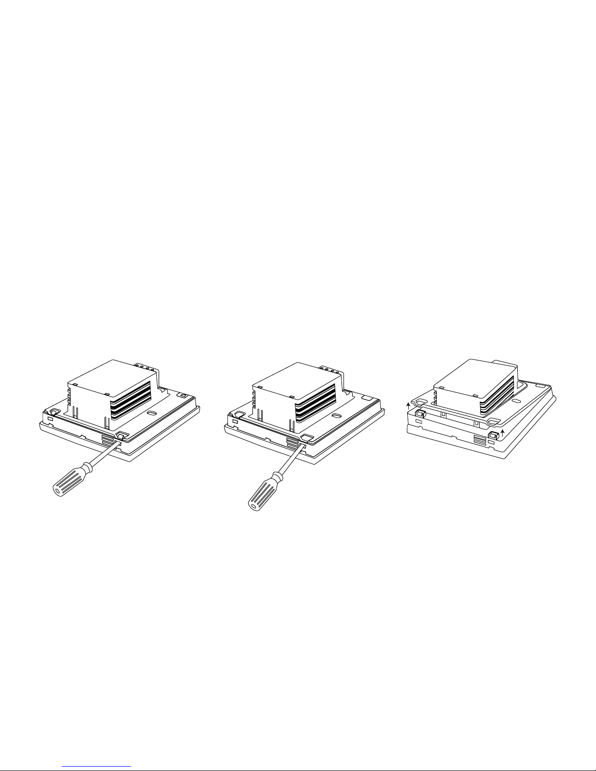
Step 1: Switch off the power supply
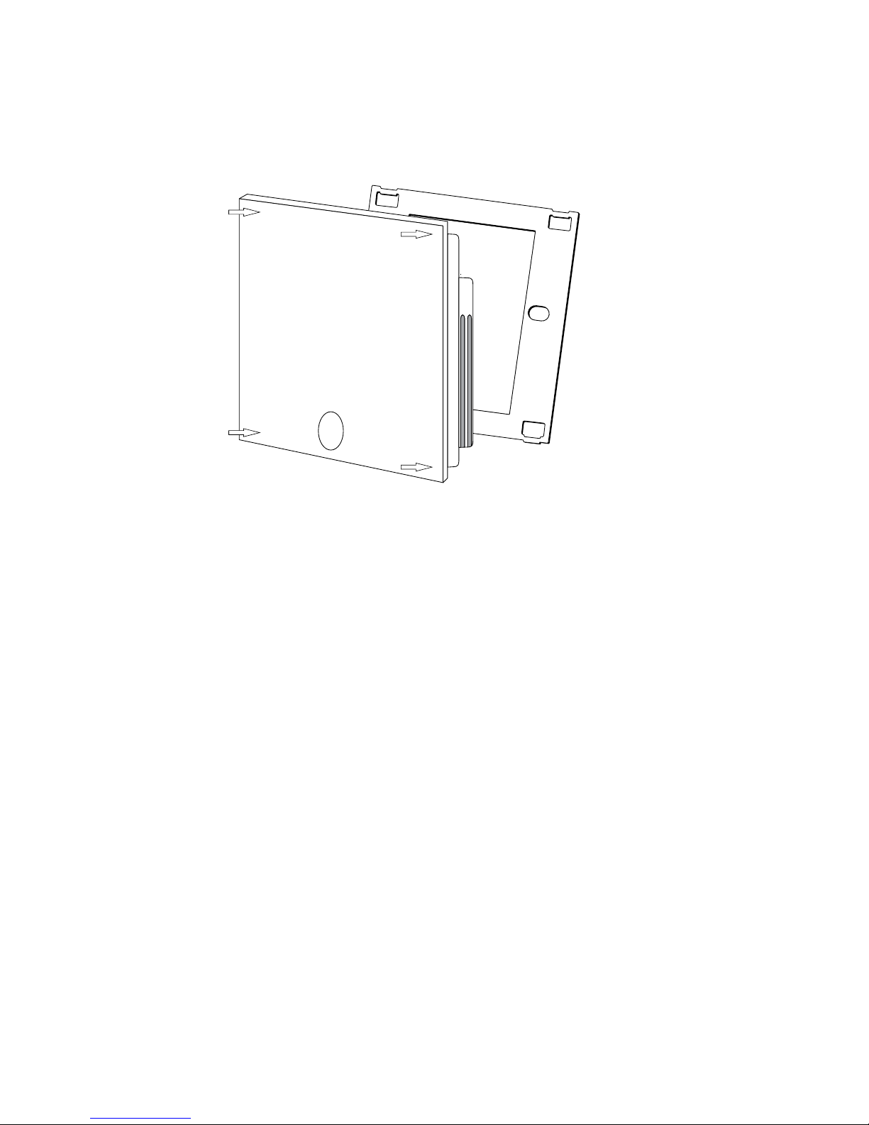
Step 2: Detach the metallic support from the
Thermostat using a screwdriver
Page 5
5
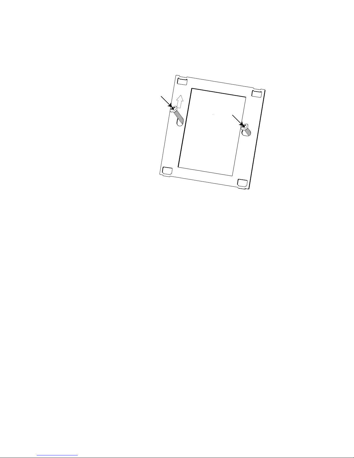
Step 3: Screw the metallic support frame to the
in-wall box
Step 4: Install the floor sensor (mandatory for floor
sensing mode or room sensing mode with floor
temperature limiter). The floor sensor should be
installed in a separate flexible conduit all the way
to the end, covering the end of the sensor, for easy
replacement and to avoid possible signal disturbance
on the sensor. For best control performance, position
the floor sensor between two heating cables as close
as possible to the top floor surface.
Do not position the floor sensor tip closer than 3 cm to
the heating cable.
The floor sensor cable can be extended up to 100 m
with a separate standard installation cable 2 x 1.5 mm
2
(230VAC).
Page 6
6
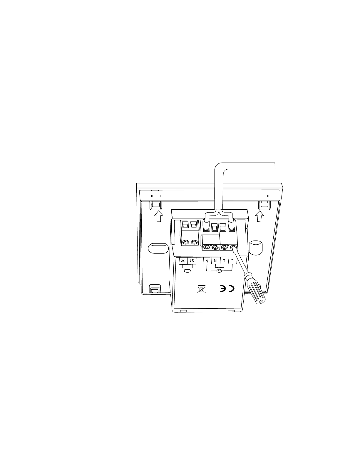
Step 5: Connect the electrical power supply, the
sensor and the cold lead of the electrical floor heating
system to the Green Leaf according to the electrical
diagram. If you connect heating cables exceeding
13A for constant wattage or 10A for self-regulating
cables you must use a contactor with an integrated
suppression device.
For the earth connection of the floor heating, you must
use a separate earth terminal connection block.
PENTAIR Green Leaf
230VAC-50H
Z
T40
13A
IP20
sensor
Page 7

7
NTC
Floor
Sensor
Heating cable
230 VAC
Max. 13A*
Power supply
230 VAC
Direct connection - e.g. single heating circuit
* Max 13A for constant wattage cable, Max 10A for self-regulating cables
10K
N
L
L N
PE
PE
PE
NTC
Floor
Sensor
Connection via contactor - e.g. 3 heating circuits
Do not use contactor without suppression device.
10K
L N
L1
PE
A1
A2K1
Power supply
230 VAC
K1: contactor with
suppression device
NTC
Floor
Sensor
Power supply
heating cables
Connection via contactor - e.g. 3 heating circuits
Do not use contactor without suppression device.
10K
L N
L1
12345
6
L2 L3PEN
N N N
L L L
PE
A1
A2K1
Power supply
230 VAC
K1: contactor with
integrated
suppression device
Page 8
8
Step 6: Click the Green Leaf into the metallic support
frame.
Step 7: Switch on the power again
Product specific information
The thermostat is compatible with CeraPro,
T2QuickNet, T2Blue, T2Red heating solutions.
T2QuickNet
T2QuickNet heating mats are approved with the Green
Leaf thermostat working in floor sensor mode. Be
aware that the floor sensor must be installed and
activated for any installation with T2QuickNet.
T2Red
Self-regulating heating cables have an inrush current
when the floor is cold. In order to guarantee the life time of
the thermostat, the maximum load of the self-regulating
application in nominal conditions is limited to 10A.
A 13A self-regulating load will reduce the life time of
the relay contacts.
Page 9

9
3.USING THE THERMOSTAT
The Display
Display in manual on/off programme
The following icons are visible in the Manual ON/OFF:
Active sensor display
• Floor sensing mode (
)
• Room Sensing mode (
)
• Room Sensing mode with Floor
temperature limiter (
)
Heating display
The heating display is flashing when the heating is on.
Page 10

10
Temperature
The temperature on the display depends on the
selected sensing mode.
• Floor sensing mode => Floor temperature
on the display
• Room sensing mode => Room temperature
on the display
• Room sensing with floor temperature
limiter mode => Room temperature on
the display
Remark: When pushing on the “
” or “ ” button,
the set point temperature appears on the display
blinking for 5 seconds
Installer Menu
• Press on the M button for 5 seconds to
enter the Installer Menu
Display in timer programme
The following icons are visible in the Timer Programme:
Page 11

11
Time and day
The actual day is displayed on the screen with the 3
letters (MON-TUE-WED-THU-FRI-SAT-SUN).
The time can be set in 24H or 12AM/PM mode
(see INSTALLER MENU).
4 Event display
The 4 events are displayed with the symbols:
Event 1
Event 2
Event 3
Event 4
The manual on/off programme
When switching on the thermostat for the first time
(pressing on the Green Leaf button for 2 seconds), it
will start in MANUAL ON/OFF programme using the
floor sensing mode as a standard (see INSTALLER
MENU to change the sensing mode).
You will see the following screen:
Page 12

12
Press the “ ” or the “ ” to show the set point
temperature. It will blink for 5 seconds.
1. Press the “
” within the 5 seconds => set point =
set point - 0.5°C
2. Press the “
” within the 5 seconds => set point =
set point + 0.5°C
To switch from Manual ON/OFF to Timer Programme,
press on the “
” button once.
To switch off the thermostat, press on the
“
” button for 2 seconds.
The timer programme
The Green Leaf can be programmed with 4 events per
day. Different temperatures can be maintained for
each event of the day. The days can be programmed
independently or per cluster of days.
The default Timer Programme is shown on the graph
below. You can easily adapt the programme to your
needs (see PROGRAMMING THE TIMER PROGRAMME)
25
20
15
10
5
0
0:00
1:00
2:00
3:00
4:00
5:00
6:00
7:00
8:00
9:00
10:00
11:00
12:00
13:00
14:00
15:00
16:00
17:00
18:00
19:00
20:00
21:00
22:00
23:00
MON-TUE-WED-THU-FRI SAT-SUN
16
23
23
16
16
Page 13

13
25
20
15
10
5
0
0:00
1:00
2:00
3:00
4:00
5:00
6:00
7:00
8:00
9:00
10:00
11:00
12:00
13:00
14:00
15:00
16:00
17:00
18:00
19:00
20:00
21:00
22:00
23:00
0:00
1:00
2:00
3:00
4:00
5:00
6:00
7:00
8:00
9:00
10:00
11:00
12:00
13:00
14:00
15:00
16:00
17:00
18:00
19:00
20:00
21:00
22:00
23:00
25
20
15
10
5
0
MON-TUE-WED-THU-FRI SAT-SUN
16
16
23
23 23
16
16
• Press on the “ ” button to set the clock and day of
the week
• Press on the “
” button for 3 seconds to program
the timer programme (see page 14 for more details).
• Press on the “
” button for 5 seconds to enter
the Installer Menu
• Press on the “
” button to switch from Timer to
Manual ON/OFF mode
• Press on the “
” button for 2 seconds to put the
Thermostat into OFF (standby) mode
• Press the “
” or the “ ” to show the set
point temperature. It will blink for 5 seconds
3. Press the “
” within the 5 seconds =>
set point = set point - 0.5°C
4. Press the “
” within the 5 seconds =>
set point = set point + 0.5°C
Remark: The adapted temperature is valid until the
next timer Event.
Page 14

14
4. SETTING THE CLOCK
• Press on the “ ” button to set the clock
and day of the week
• Press the “
” or the “ ” to change
the hours
• Press on the “
” button to validate
• Press the “
” or the “ ” to change
the minutes
• Press on the “
” button to validate
• Press the “
” or the “ ” to change
the day of the week
• Press on the “
” button to validate
Remark: In case of battery drainage after
long period of power failure, you might have to
re-programme the clock
Page 15

15
5. PROGRAMMING THE TIMER PROGRAMME
• Press on the “ ” button for 3 seconds to
program the Timer Programme
• Press the “
” or the “ ” to choose the day
(or the sequence of days) you want to program
• Press on the “
” button to validate
Day Sequences are:
MON
TUE
WED
THU
FRI
SAT
SUN
MON TUE WED THU FRI
SAT SUN
MON TUE WED THU FRI SAT SUN
Page 16

16
For Event 1
• Press the “ ” or the “ ” to change
hours of Event 1
• Press on the “
” button to validate
• Press the “
” or the “ ” to change the
minutes of Event 1
• Press on the “
” button to validate
• Press the “
” or the “ ” to change the
set point temperature for Event 1
• Press on the “clock” button to validate
For Event 2, 3 and 4
• Repeat the actions for event 1 for the
Events 2, 3 and 4
Press on the “
” button, at any time during the
programming, to save your changes and return to the
Timer Programme.
If needed, you can repeat the complete procedure to
program other days or sequences of days.
Page 17

17
6. INSTALLER MENU
Press on the “ ” button for 5 seconds to enter the
installer Menu
# Description Range Default
setting
1 Sensing mode
selection
Floor sensing mode
Room sensing mode
Room sensing mode with
floor temperature limiter
Floor
Sensing
mode
2 12 vs 24 hours
display
12 / 24 24
3 Motion sensor.
When getting close
to the thermostat
(5cm range) the
display lights up
automatically
ON / OF ON
4 Floor sensor
calibration (Floor
sensor on display =
Real Floor sensor
°C – OFFSET)
0 .. 10°C 4°C
Page 18

18
# Description Range Default
setting
5 Room sensor
calibration
Measured sensor
temperature +/- 5°C
Measured
sensor
temperature
6 Minimum
temperature
set point for the
Floor Sensor
Floor sensing mode:
5 .. 15°C
Room sensing mode: OF
Room sensing mode
with floor temperature
limiter: OF
5°C
OF
OF
7 Maximum
temperature
set point for the
Floor Sensor
Floor sensing mode:
Minimum temperature
set point floor sensor
(installer menu 6)
+5°C .. 35°C
Room sensing mode: OF
Room sensing mode
with floor temperature
limiter: 10 .. 35°C
35°C
OF
27°C
8 Minimum
temperature
set point for the
Room Sensor
Floor sensing mode: OF
Room sensing mode:
5 .. 15°C
Room sensing mode
with floor temperature
limiter: 5 .. 15°C
OF
5°C
5°C
Page 19

19
# Description Range Default
setting
9 Maximum
temperature
set point for the
Room Sensor
Floor sensing mode: OF
Room sensing mode:
Minimum temperature
set point room sensor
(installer menu 8)
+5°C .. 40°C
Room sensing mode
with floor temperature
limiter: Minimum
temperature set point
room sensor (installer
menu 8) +5°C .. 40°C
OF
40°C
40°C
10 Adjustable
hysteresis
0.5 .. 2.0°C 1.0°C
Page 20

20
Floor sensor calibration
The temperature of the floor surface can differ from
the temperature measured by the floor sensor due
to the floor construction, the floor type and the
position of the floor sensor. In order to calibrate your
thermostat to this difference you can use the floor
sensor calibration OFFSET in installer Menu 4.
After the temperature on the floor is stabilized, place a
thermometer on the floor surface in order to sense the
real temperature on the surface (Tsurface). Read the
floor sensor temperature (Tsensor) on the thermostat
and adjust the OFFSET accordingly to the formula:
Tsensor
Tsurface
OFFSET = Tsensor - Tsurface
Room sensor calibration
If the value measured by the room sensor in the
thermostat differs from the real room temperature,
it is possible to calibrate the room sensor using the
installer Menu 5.
After the temperature in the room is stabilized, place
a thermometer close to the wall in order to sense the
real room temperature. If this value differs from the
one shown by the thermostat, adjust Menu 5 using the
“
” or the “ ” until the thermostat shows the same
value as the reference thermometer.
Page 21

21
7. TROUBLESHOOTING
In the event of damage or malfunction of one of the
temperature sensors, the heating output cuts off (fail
safe) and an error code is displayed.
Error Code Description
ER1 Short circuit on floor sensor
ER2 Open circuit on floor sensor /
Missing floor sensor
ER3 Short circuit on room sensor
ER4 Open circuit on room sensor
ER5 Check sensing mode
The floor sensor can be replaced by a new one. In the
event of malfunction of the room sensor, the entire
thermostat must be replaced.
The floor sensor has got the following temperature/
resistance values:
Temperature Resistance
15°C 15.8 kΩ
20°C 12.5 kΩ
25°C 10.0 kΩ
30°C 8.0 kΩ
35°C 6.5 kΩ
Error 5 occurs if the thermostat is set in Room
Sensing Mode and the floor sensor is installed.
To resolve the error change the sensing mode in Floor
sensing or Room sensing with floor temperature
limiter. Otherwise, remove the floor sensor to work in
room sensing mode.
Page 22

22
8. TECHNICAL SPECIFICATION
Supply voltage 230VAC, +10%, –15%, 50Hz
Power consumption (Stand-by) 3 VA
Relay output 230V, maximum 13A resistive
load (max. 3000W)
Ambient temperature – operation 0 .. 40°C, 5-95% RH (non
condensing)
Ambient temperature – transport –10 .. +60°C
Temperature range, floor sensor +5 .. +35°C
Temperature range, room sensor +5 .. +40°C
Switching hysteresis 1°C (Factory settings adjustable
between 0.5-2.0°C)
Control modes Floor sensing
Room sensing
Room sensing with floor
temperature limiter
Temperature control Manual ON/OFF
Timer programme
Protection class IP 20
Terminals Max. 2,5 mm²
Floor sensor with 3 m cable NTC, 10KΩ / 25°C
Maximum length of floor sensor
Cable
100 m, 2 x 1,5 mm² (230VAC
cable type)
Approvals CE
Page 23

23
Page 24

THERMAL MANAGEMENT SOLUTIONS EN-RaychemGreenLeaf-IM-EU0209 R1
PCN 1244-013904
WWW. PENTAIRTHERMAL.COM
All Pentair trademarks and logos are owned by Pentair or its global affiliates. Pentair reserves the right to
change specifications without prior notice.
© 2013 Pentair.
EuropEan hEadquartErs
Tel: +32 16 21 35 02
Fax: +32 16 21 36 04
salesbelux@pentair.com
unItEd KInGdoM
Tel: +0800 96 90 13
Fax: +0800 96 86 24
salesthermaluk@pentair.com
 Loading...