

Page 1
FrostGuard 240 V
Table 1 Metal Pipes
Pipe diameter (in)
240 V PREASSEMBLED ELECTRIC HEATING CABLES FOR PIPE FREEZE PROTECTION
INSTALLATION INSTRUCTIONS
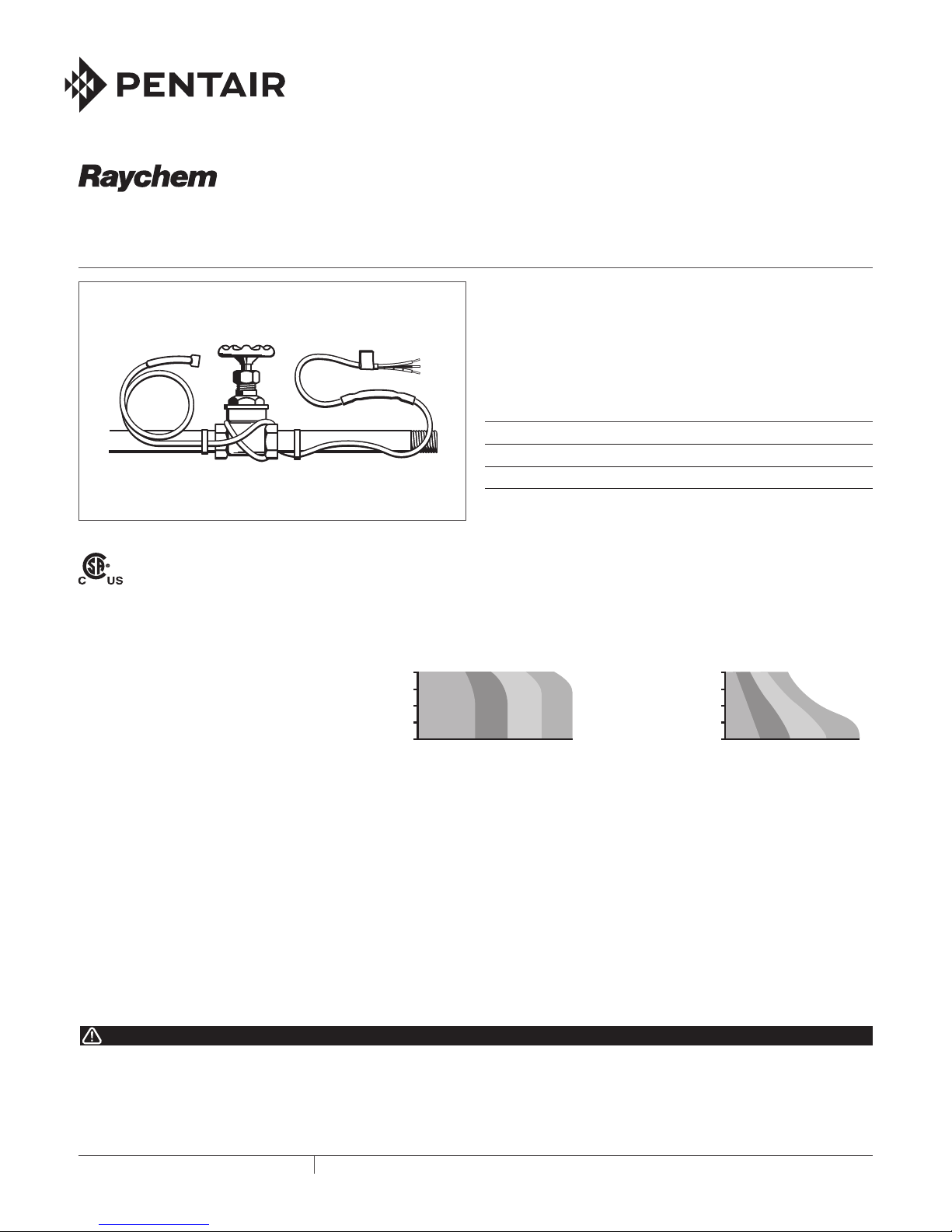
DESCRIPTION
FrostGuard 240 V preassembled electric heating cables are
intended for installation on metal or plastic water pipes for freeze
protec tion in commercial locations. FrostGuard 240 V heating
cables are available in 6-, 12-, 18-, and 24-foot lengths and each
comes complete with a 6-ft cold lead.
KIT CONTENTS
Item Qty Description
1 FrostGuard preassembled heating cable
3 Wire connectors
ADDITIONAL MATERIALS REQUIRED
APPROVALS
-W
1 UL Listed or CSA Certified junction box suitable for wet or dry areas
1 UL Listed or CSA Certified outlet bushing and fitting
Cable ties or glass-cloth tape
Thermal pipe insulation
HEATING CABLE SELECTION
FrostGuard 240 V (FG2) heating cable
selection for pipe freeze protection:
Use the tables to the right to select the
correct heating cable. Round up to the next
pipe size if your pipe diameter isn’t shown.
The charts assume the lowest ambient
temperature is –20°F (–29°C), with a
minimum of 1/2 in fiberglass insulation or
equivalent. For protection to –40°F (–40°C),
use 1 inch fiberglass insulation or equivalent
fire-resistant insulation.
Add 1 foot to your pipe length for each valve
or spigot on your pipe system. If length of
cable selected is longer than the pipe, spiral
cable evenly along the entire pipe.
FIRE AND SHOCK HAZARD. This product is an electrical device
that must be installed correctly to ensure proper operation and to
prevent shock or fire. Read these important warnings and carefully
follow all the installation instructions.
• To minimize the danger of fire from sustained electrical arcing if the
heating cable is damaged or improperly installed, and to comply
THERMAL BUILDING SOLUTIONS
WARNING:
Table 2 Plastic Pipes
2 1/2
2
1 1/2
1
1/2
FG2-6LFG2-
12L
FG2-
18L
FG2-
24L
2 1/2
2
1 1/2
1
1/2
Pipe diameter (in)
FG2-6LFG2-
12L
FG2-
18L
10 20010 200
Pipe length (ft)
Add 1 foot to your pipe length for each valve or spigot on your pipe system.
If cable selected is longer than the pipe, spiral it evenly along the entire pipe.
Important
All thermal and design information provided here is based upon a “standard installation”: heating cable fastened to a pipe and thermally insulated. For any other method of
installation or application, consult Pentair Thermal Building Solutions at (800) 542-8936
for design assistance to ensure proper design of electrical distribution and acceptable
pipe temperatures.
with the requirements of Pentair Thermal Building Solutions,
agency certifications, and the National Electrical Code, ground-fault
equipment protection must be used on each heating cable branch
circuit. Arcing may not be stopped by conventional circuit protection.
• Use only fire-resistant insulation materials such as fiberglass
wrap.
EN-RaychemFrostGuard240V-IM-H5948705/16
• Do not damage the heating cable and cord connector. Remove
any damaged cables from service immediately.
• Do not use any wire or metal clamps to attach the cable to the
pipe. Use tape (1/2 inch wide to 1 inch wide) or plastic cable ties.
• Leave these installation instructions with the user for future
reference.
Pipe length (ft)
FG2-
24L
1 / 4
Page 2
GENERAL REQUIREMENTS:
GENERAL INSTRUCTIONS:
• FrostGuard heating cables are not intended for use inside any
pipes, for freeze protection of liquids other than water, or for
use in classified hazardous locations.
• FrostGuard heating cables may be used on metal and plastic
water pipes but not on flexible vinyl tubing (such as garden
hoses).
• Install with a minimum of 1/2 inch fire-resistant thermal insulation. Weatherproof the insulation if it might get wet.
• Never use on any pipes that may exceed 150°F (65°C).
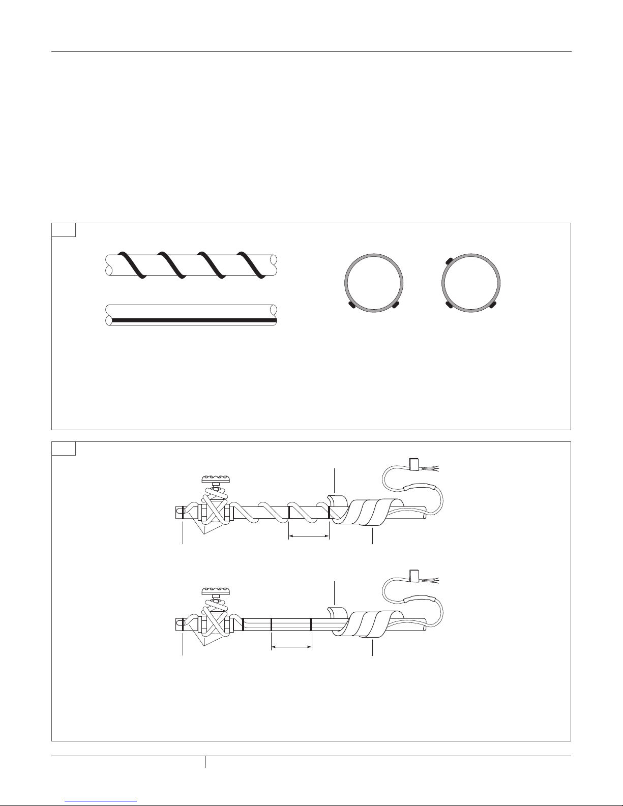
1
Side View
1a Spiral traced
1b Straight traced
• If your FrostGuard cable is longer than the pipe, spiral it
evenly along the pipe (Figure 1a).
• If your FrostGuard cable is the same length as the pipe, run
it straight along the pipe (Figure 1b) in the 4 o’clock or 8
o’clock position.
• Install only in accessible locations; do not install behind walls or
where the cable would be hidden.
• Do not run the heating cable through walls, ceilings, or floors.
• Connect only to junction boxes that have been installed in accordance with all prevailing national and local codes and standards
and are protected from rain and other water.
• Prior to installing the cable, remove any sharp surfaces on the
pipe that might damage the heating cable.
• Follow the specific installation instructions that begin below.
• Follow the maintenance guidelines on page 3.
End View
1c Two cables in
4 and 8 o’clock
positions
1d Three cables in
4, 8, and 10 o’clock
positions
• If two FrostGuard cables are used, position them in the 4
o’clock and 8 o’clock positions (Figure 1c).
• If three FrostGuard cables are used, position them in the 4, 8,
and 10 (or 2) o’clock positions (Figure 1d).
2
240 V heating cable
Tape or cable ties
Spiral-traced Installation
240 V heating cable
Tape or cable ties
12 inches
Straight-traced Installation
• Fasten the cable to the pipe at 12-inch intervals with glass
cloth tape or plastic cable ties. If excess cable remains at
the end of the pipe, double it back along the pipe and cover it
with insulation.
1/2 in. insulation
12 inches
Waterproof covering
1/2 in. insulation
Waterproof covering
• Provide extra heat at valves and spigots by wrapping each
with an additional foot of heating cable, overlapping as required.
THERMAL BUILDING SOLUTIONS
EN-RaychemFrostGuard240V-IM-H5948705/16
2 / 4
Page 3

3 4
Thermal insulation
• Before installing the thermal insulation, check to see that
the heating cable is free from mechanical damage (such
as from cuts or clamps) and thermal damage (such as
from solder or overheating).
• Using a megohmmeter, test each circuit according to the
“Cable testing and maintenance" instructions below, both
prior to and after installing the thermal insulation.
Note: A reliable FrostGuard system depends on properly
installed and dry, weatherproofed thermal insulation.
• Ensure that at least 1/2 inch of fiberglass or equivalent
thermal insulation is used and that all pipework, including valves, joints, and wall penetrations, has been fully insulated. To minimize the potential for mechanical damage
after installation, install the insulation on the pipework as
soon as possible.
• Be sure the FrostGuard 240 V label is visible on the outside of the thermal insulation.
Connecting the FrostGuard cable to power
Using the three wire connectors included in the kit, connect
the black and white cold leads to both phase wires and the
green cold lead to ground. Provide suitable UL Listed and
CSA Certified junction box and outlet bushing and fitting.
CABLE TESTING AND MAINTENANCE
Using a 2500-Vdc megohmmeter, check the insulation resistance
between the lead wires and ground wire during installation.
Minimum reading should be 1000 megohms.
The installer should record the original values for each circuit.
Subsequent readings taken during regular maintenance schedules
should be compared to the original value.
If the readings should fall below 1000 megohms, replace the
FrostGuard cable with a new unit. Do not attempt to repair the unit.
WARNING: Fire and Shock Hazard. Damaged heating
cable can cause electrical shock, arcing, or fire. Do
not attempt to repair or energize damaged heating
cable. Remove it at once and replace with a
new length.
EN-RaychemFrostGuard240V-IM-H5948705/16
3 / 4THERMAL BUILDING SOLUTIONS
Page 4

Product Specifications
FG2-6L FG2-12L FG2-18L FG2-24L
Cable length (ft/m) 6 (1.8) 12 (3.7) 18 (5.5) 24 (7.3)
Min. thermal output on a pipe at 40°F/4°C (watts) 30 60 90 120
Min. thermal output on a pipe at 0°F/–18°C (watts) 46 92 138 184
Max. current draw on a pipe at 40°F/4°C (amps) 0.21 0.43 0.64 0.85
Max. current draw on a pipe at 0°F/–18°C (amps) 0.32 0.64 0.96 1.28
General Specifications for all FG2 Products
Maximum cable width (inch/mm) 0.45 (11.4)
Maximum cable thickness (inch/mm) 0.24 (6.1)
Heating cable bus wire gauge (AWG) 16
Voltage rating (Vac) 208–240
Circuit breaker size 15 A max.
Cold lead length (ft/m) 6 (1.83)
Maximum exposure temperature 150°F (65°C)
Minimum installation temperature 5°F (–15°C)
Minimum bend radius (inch/mm) 5/8 (16)
Electrical classification Nonhazardous areas only
Exposure to chemicals None
NORTH AMERICA
Tel: +1.800.545.6258
Fax: +1.800.527.5703
Tel: +1.650.216.1526
Fax: +1.650.474.7711
thermal.info@pentair.com
Pentair and FrostGuard are owned by Pentair or its global affiliates. All other trademarks are the property of their respective owners. Pentair reserves the
right to change specifications without prior notice.
©2016 Pentair.
EN-RaychemFrostGuard240V-IM-H5948705/16 PN P000002073
WWW.PENTAIRTHERMAL.COM
4 / 4THERMAL BUILDING SOLUTIONS
 Loading...