

Page 1
AMC-1A
WARNING:
Ambient-sensing thermostAt for nonhAzArdous locAtions instAllAtion instructions
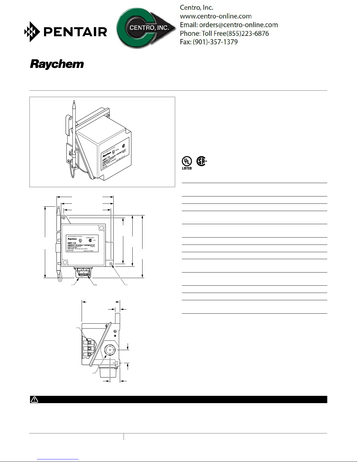
Description
The AMC-1A thermostat is designed for controlling freeze
protection heat-tracing systems in nonhazadous locations. The
thermostat responds to ambient temperature changes. The
AMC-1A can be used to control a heat-tracing circuit directly (see
Figure 1 on back page) or it can be used to control a contactor coil
(see Figure 2).
8.0 in
(202 mm)
Removable
knob cover
4.9 in (124 mm)
4.5 in (114 mm)
4.0 in (102 mm)
3.0 in (76 mm)
Adjusting
knob
R
4.0 in
(102 mm)
4.5 in
(114 mm)
5.6 in
(142 mm)
Ø.28 in (7 mm)
mounting holes (2X)
0.3 in
(9 mm)
ApprovAls
specificAtions
Enclosure NEMA 4X, polyurethane-coated cast-
aluminum housing, stainless-steel hardware
Entries One 3/4 in. NPT conduit hub
Set point range 15°F to 140°F (–9°C to 60°C)
Sensor exposure
limits
Housing exposure
limits
Switch SPDT
Electrical rating 22 A at 125/250/480 Vac
Accuracy ±6°F (±3.3°C)
Deadband 2°F to 12°F (1.1°C to 6.7°C) above actuation
Set point
repeatability
Sensor type Fixed fluid-filled (silicone) bulb and capillary
Sensor material 300 series stainless steel
Connection
terminals
–40°F to 160°F (–40°C to 71°C)
–40°F to 160°F (–40°C to 71°C)
temperature
±3°F (±1.7°C)
Screw terminals, 10–14 AWG (2–5 mm
2
)
Terminal
block
NPT conduit entry
This component is an electrical device. It must be installed
correctly to ensure proper operation and to prevent shock or
fire. Read these important warnings and carefully follow all the
installation instructions.
3⁄4 in
IndustrIal Heat tracIng solutIons EN-RaychemAMC1A-IM-H569089/15
1.2 in
(30 mm)
0.8 in
(20 mm)
Component approvals and performance are based on the use of
specified parts only. Do not use substitute parts or vinyl electrical
tape to make connections.
1 / 2
Page 2
instAlling the thermostAt
1. Verify that the thermostat is suitable for the area where it is to
be installed.
2. Check the line voltage and the
heat-tracing load to ensure that
the thermostat ratings are not
exceeded.
3. Mount the unit in a position that
prevents condensation from
draining into the enclosure from
Conduit
drain
positioning
4. Mount ambient-sensing units in the area exposed to the
coldest temperature and the most wind. Do not mount on the
side of a warm building or in a location that is exposed to warm
air currents or direct sun light.
setting AnD ADjusting
5. Set the thermostat dial to the desired temperature and finish
wiring.
the connecting conduit (see diagram above).
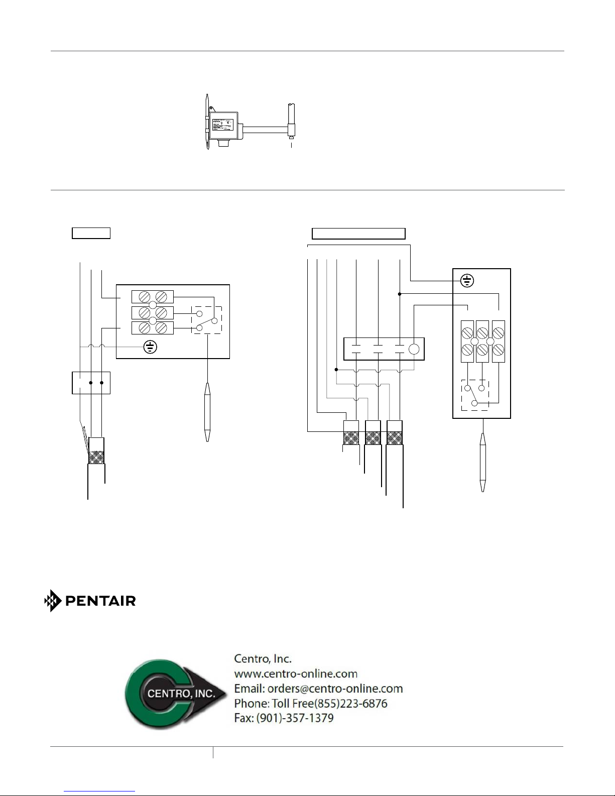
Wiring
Power Supply Power Supply
GFEPD
ØØ
G
120-V supply – 120-V heating cable
N
Ø
277-V supply – 240-V heating cable
C
NO NC
208-V or 240-V supply - 240 -V heating cable
or
Control
thermostat
GCNANBN
C
GFEPD
Ø
A
B
277-V supply – 240-V heating cable
NONC
C
120-V supply – 120-V heating cable or
Ø
Ø
C
Control
thermostat
G
Power
connection
Braid
Heating
Cable
NORTH AMERICA
Tel: +1.800.545.6258
Fax: +1.800.527.5703
Tel: +1.650.216.1526
Fax: +1.650.474.7711
thermal.info@pentair.com
EuROPE, MIddLE EAsT, AfRICA
Tel: +32.16.213.511
Fax: +32.16.213.603
thermal.info@pentair.com
120-V or
277-V
coil
Braid
Heating
Cable A
Heating
Cable B
Heating
Cable C
Figure 2. Controlling a contactorFigure 1. Heat-tracing control
For switching heat-tracing loads greater than 22 A
or switching multiple heat-tracing circuits.
AsIA PACIfIC
Tel: +86.21.2412.1688
Fax: +86.21.5426.2937
cn.thermal.info@pentair.com
NONC
C
WWW.PENTAIRTHERMAL.COM
LATIN AMERICA
Tel: +1.713.868.4800
Fax: +1.713.868.2333
thermal.info@pentair.com
Pentair and AMC are owned by Pentair or its global affiliates. All other trademarks are the property of their respective owners. Pentair reserves the right
to change specifications without prior notice.
© 2001-2015 Pentair. PN 689375
IndustrIal Heat tracIng solutIons EN-RaychemAMC1A-IM-H569089/15
2 / 2
 Loading...