

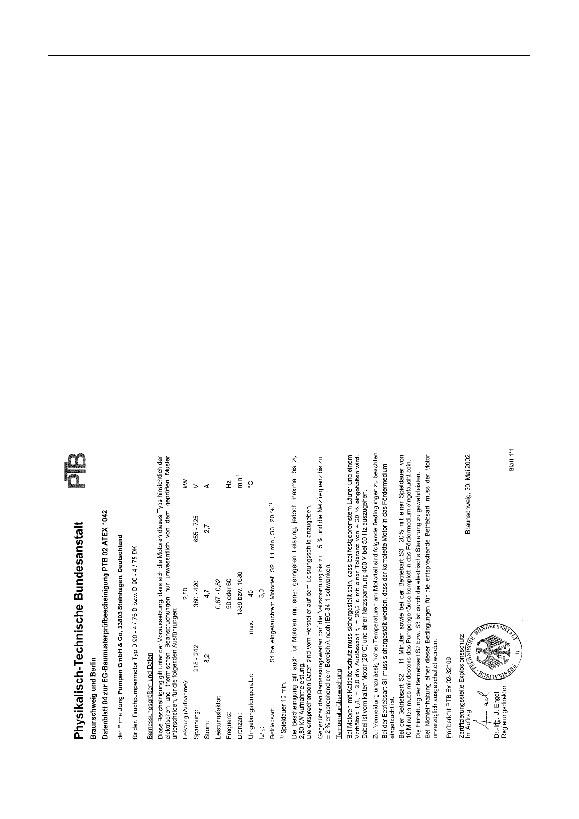
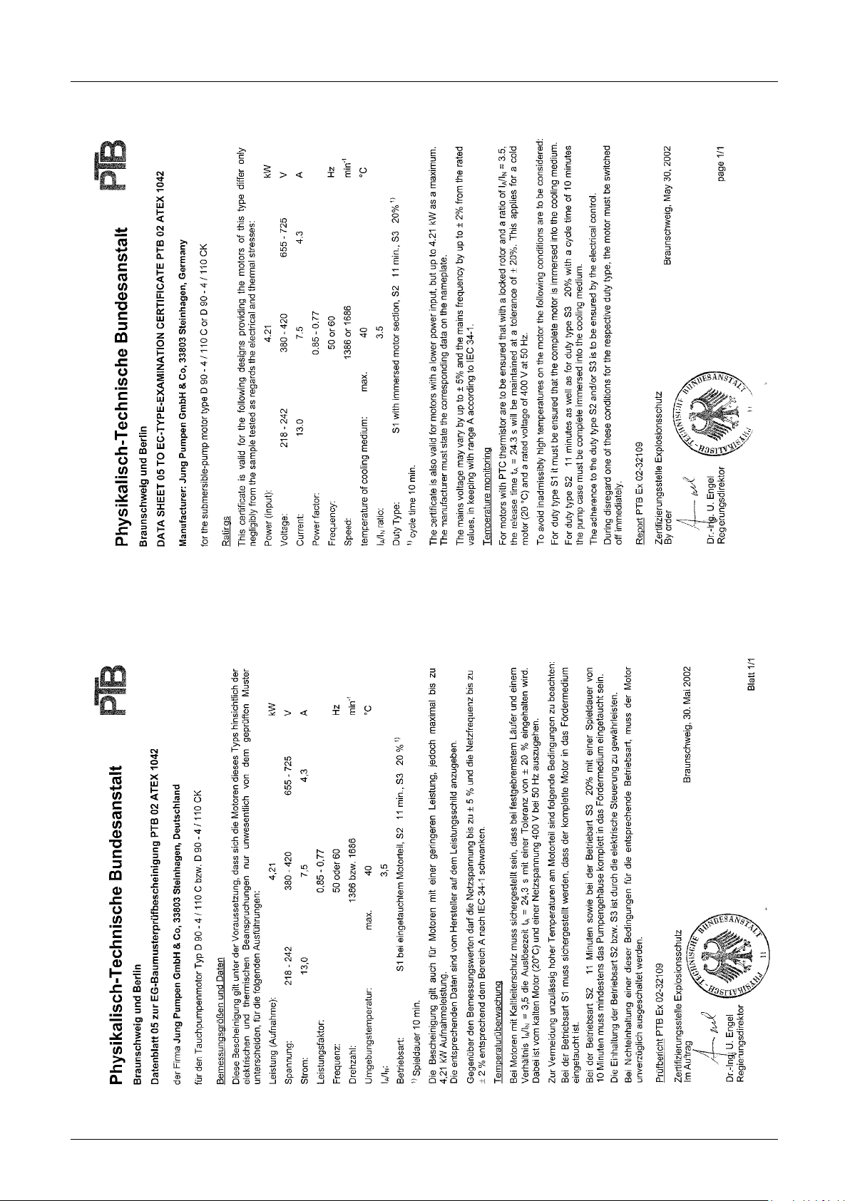
Pentair Multistream 25/2 B1, Multistream 15/2 A1, Multistream 35/2 B2, Multistream 10/4 B1, Multistream 15/4 B3 Instruction Manual
...
EN Instruction Manual
MULTISTREAM
10/2 A1 15/2 A1 25/2 A2 35/2 A2 25/2 B1 35/2 B2
10/4 B1 15/4 B3 25/4 B4 35/4 B4 25/4 C1 35/4 C1
10/2 A1 EX 15/2 A1 EX 25/2 A2 EX 35/2 A2 EX 25/2 B1 EX 35/2 B2 EX
10/4 B1 EX 15/4 B3 EX 25/4 B4 EX 35/4 B4 EX 25/4 C1 EX 35/4 C1 EX
UC 25/4 C1 UC 35/2 B2 UC 35/4 C1
15/26 A1 25/26 A2 10/46 B1 15/46 B3 25/46 B4
JUNG-PUMPEN.DE B 41992-26-1810

ENGLISH
You have purchased a product made by Pentair Jung Pumpen and with it, therefore, also excellent quality and service.
Secure this service by carrying out the installation works
in accordance with the instructions, so that our product
can perform its task to your complete satisfaction. Please
remember that damage caused by incorrect installation or
handling will adversely affect the guarantee. Therefore please adhere to the instructions in this manual!
This appliance can be used by children aged 8 years or over
and by persons with limited physical, sensory or intellectual
capabilities, or with limited experience and knowledge, provided that they are supervised or have been instructed in
the safe use of the appliance and are aware of the dangers
involved. Children must not be allowed to play with the appliance. Cleaning and user maintenance must not be carried
out by children unless they are supervised.
Damage prevention in case of failure
Like any other electrical device, this product may fail due to a
lack of mains voltage or a technical defect.
If damage (including consequential damage) can occur as a result of product failure, the following precautions can be taken
at your discretion:
• Installation of a water level dependent (under circumstan-
ces, mains-independent) alarm system, so that the alarm
can be heard before damage occurs.
• Inspection of the collecting tank/chamber for tightness up
to the top edge before – or at the latest, during – installation
or operation of the product.
• Installation of backow protection for drainage units that
can be damaged by wastewater leakage upon product
failure.
• Installation of a further product that can compensate in
case of failure of the other product (e.g. duplex unit).
• Installation of an emergency power generator.
As these precautions serve to prevent or minimise consequential damage upon product failure, they are to be strictly observed
as the manufacturer’s guideline – in line with the standard DIN EN
specications as state of the art – when using the product (Higher Regional Court Frankfurt/Main, Ref.: 2 U 205/11, 06/15/2012).
SAFETY INSTRUCTIONS
This instruction manual contains essential information that must
be observed during installation, operation and servicing. It is
therefore important that the installer and the responsible technician/operator read this instruction manual before the equipment
is installed and put into operation. The manual must always be
available at the location where the pump or the plant is installed.
Failure to observe the safety instructions can lead to the loss of
all indemnity.
In this instruction manual, safety information is distinctly labelled
with particular symbols. Disregarding this information can be
dangerous.
General danger to people!
Warning of electrical voltage!
NOTICE!
Danger to equipment and operation!
Qualication and training of personnel
All personnel involved with the operation, servicing, inspection
and installation of the equipment must be suitably qualied
for this work and must have studied the instruction manual in
depth to ensure that they are suciently conversant with its
contents. The supervision, competence and areas of responsibility of the personnel must be precisely regulated by the operator. If the personnel do not have the necessary skills, they
must be instructed and trained accordingly.
Safety-conscious working
The safety instructions in this instruction manual, the existing national regulations regarding accident prevention, and any internal
working, operating and safety regulations must be adhered to.
Safety instructions for the operator/user
All legal regulations, local directives and safety regulations
must be adhered to.
The possibility of danger due to electrical energy must be prevented. Leakages of dangerous (e.g. explosive, toxic, hot) substances must be discharged such that no danger to people or
the environment occurs. Legal regulations must be observed.
Safety instructions for installation, inspection and
maintenance works
As a basic principle, works may only be carried out to the equipment when it is shut down. Pumps or plant that convey harmful
substances must be decontaminated.
All safety and protection components must be re-tted and/or
made operational immediately after the works have been completed. Their effectiveness must be checked before restarting,
taking into account the current regulations and stipulations.
Unauthorised modications, manufacture of spare parts
The equipment may only be modied or altered in agreement
with the manufacturer. The use of original spare parts and accessories approved by the manufacturer is important for safety reasons. The use of other parts can result in liability for
consequential damage being rescinded.
Unauthorised operating methods
The operational safety of the supplied equipment is only guaranteed if the equipment is used for its intended purpose. The
limiting values given in the "Technical Data" section may not be
exceeded under any circumstances.
Instructions regarding accident prevention
Before commencing servicing or maintenance works, cordon
off the working area and check that the lifting gear is in perfect
condition.
Never work alone. Always wear a hard hat, safety glasses and
safety shoes and, if necessary, a suitable safety belt.
Before carrying out welding works or using electrical devices,
check to ensure there is no danger of explosion.
People working in wastewater systems must be vaccinated
against the pathogens that may be found there. For the sake of
your health, be sure to pay meticulous attention to cleanliness
wherever you are working.
Make sure that there are no toxic gases in the working area.
Observe the health and safety at work regulations and make
sure that a rst-aid kit is to hand.
In some cases, the pump and the pumping medium may be hot
and could cause burns.
For installations in areas subject to explosion hazards, special
regulations apply!
2
ENGLISH
AREAS OF APPLICATION
Submersible pumps in the MultiStream range are suitable for
pumping wastewater in municipal and industrial pumping stations, and in rainwater retention tanks. The smallest models
also perform well in disaster control applications.
MultiStream pumps are favoured for use with:
– wastewater containing bres
– wastewater containing solids (without stones)
– mixed wastewater
– untreated water
– raw sludge
– surface water and rainwater
The submersible pumps are supplied without explosion protection or with explosion protection.
When using the pumps, the relevant national laws, regulations
and stipulations must be adhered to, for example:
• Installation of low-voltage systems
(e.g., VDE 0100 in Germany)
• Safety and working materials
(e.g., BetrSichV and BGR 500 in Germany)
• Safety in wastewater systems
(e.g., GUV-VC5, GUV-R104 and GUV-R126 in Germany)
• Electrical systems and operating resources
(e.g., GUV-VA3 in Germany)
• Explosion protection
EN 60079-0, EN 60079-1, EN 60079-14, EN 1127-1.
For non-standard utilisation conditions in areas subject to explosion hazards, please ask the local authority responsible.
In Germany, this would be, for example, the Trade Supervisory
Centre (Gewerbeaufsicht), the Technical Inspection Agency
(TÜV), the building authority (Bauamt) or professional organisation (Berufsgenossenschaft).
The installation and operation of this equipment is regulated by
the ordinance concerning the protection of health and safety in
the provision of work equipment and its use at work, concerning
safety when operating installations subject to monitoring, and
concerning the organisation of industrial health and safety at
work, (Betriebs sicherheitsverordnung), Article 1.
Where no explosion protection is stipulated for the pumping
of foul wastewater at the installation location, pumps without
explosion protection may also be used.
Modes of operation
with the pumped medium at a temperature of 40°C:
Motor submersed: continuous operation S1;
Motor emerged: short duration operation S2;
see "Technical Data"
Motor emerged: intermittent operation S3;
see "Technical Data"
The submersible pump is frost-resistant down to -20°C when
stored in dry conditions. When installed, however, it must not
be allowed to freeze in the water.
Transpor t
The pump must always be lifted by the shackle and never by the
power supply cable! The pump should only be lowered by using
a rope or chain.
ELECTRICAL CONNECTION
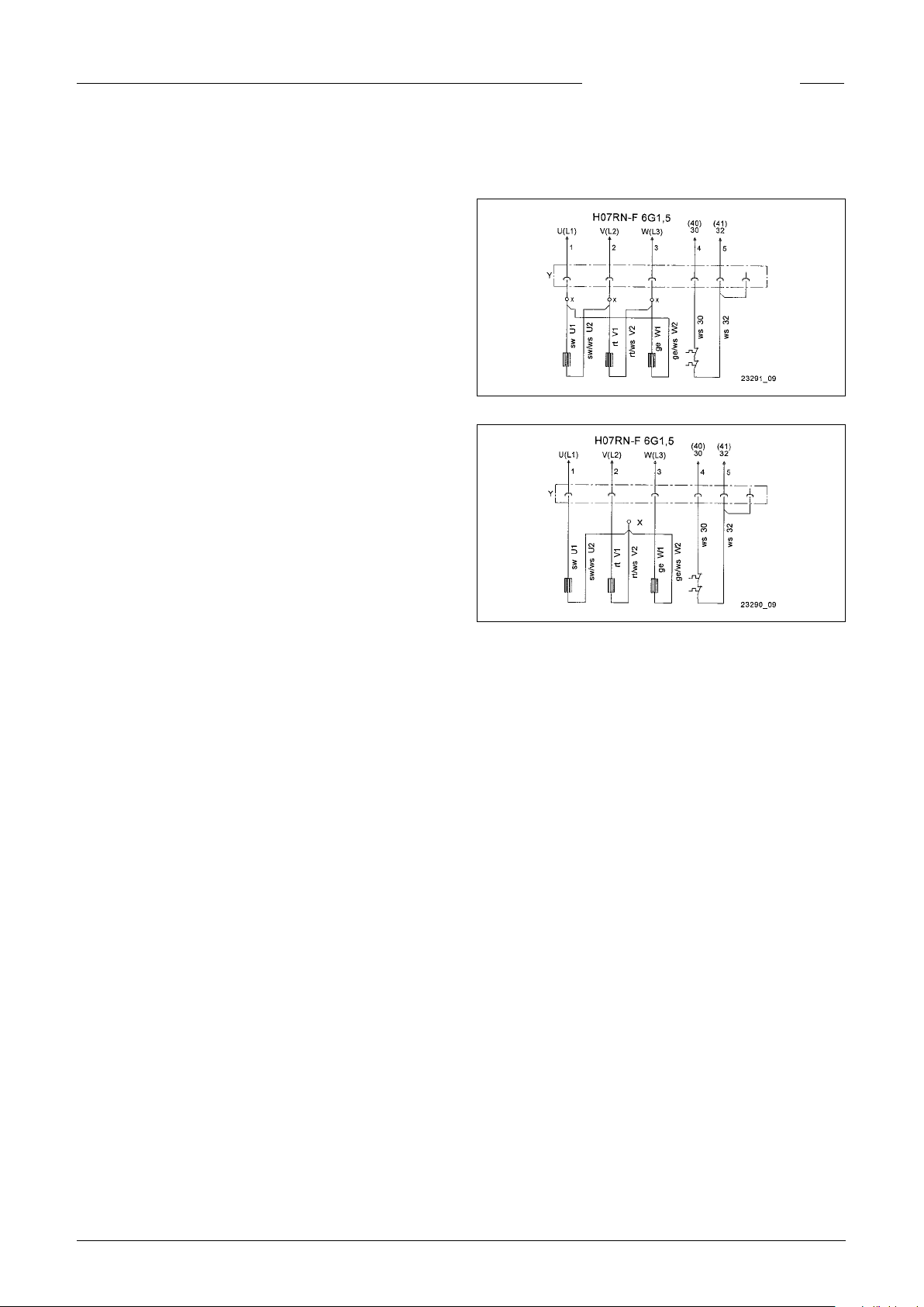
Δ-Circuitry, low voltage
Y-Circuitry, high voltage
Alterations to the circuitry are to be made using crimp connectors (X) between the coni plug connection (Y) and the builtin motor. The new crimp connection must be professionally
made.
By using our controls, you can be sure that the requirements of
the EU-type-testing certicate are met.
NOTICE! Only qualied electricians may carry out electrical
works to the pump or the controls.
NOTICE! The standards applicable in each case (e.g. EN), the
country-specic regulations (e.g. VDE in Germany), and the
regulations of the local supply network operator must be observed.
NOTICE! Never lay the end of cables in water! Penetrating water may cause malfunctions.
Only slow-blow fuses or automatic fuses with C or D characteristics are to be used as pre-fuses for the pump. Necessary fuse
protection for direct on-line start: 10 A.
The pump must be protected via an overload trip. Setting for
direct on-line start = nominal current.
If the protective device has been triggered, the cause of the
malfunction must be eliminated before switching on again.
Coil thermostats
NOTICE! In addition to the overload trip or protective switch
of the motor, the thermostats integrated in the motor winding
must also be connected. The thermostats are suitable for 250
V / 1.2 A (cos phi = 0.6) and are labelled 30 and 32 for connection
purposes.
Thermostat connection without explosion
protection
The thermostats are to be connected in such a way that the
3
ENGLISH
motor is switched off via the control circuit when the response
temperature is reached. The motor is switched on again automatically after the winding has cooled down.
Thermostat connection with explosion
protection
The thermostats are to be connected in such a way that the
motor is switched off via the control circuit when the response
temperature is reached. It must not be possible for the motor
to switch on again automatically after the winding has cooled
down.
WARNING!
After an automatic cut-out via the temperature limiters, the
cause of the malfunction must rst be eliminated. Only then
may the motor be switched on again manually.
The restart interlock must be "non-resetting on power failure",
i.e. the lock must be in place to prevent restarting even after a
power cut (in Europe: Directive 2014/34/EU, Appendix II 1.5, EN
60079-17 Table1, B10).
Operation with frequency converter
Frequency converters may only be used for controlling the frequency of special models of three-phase pumps.
NOTICE! For physical reasons, pumps may not be operated at a
higher frequency than that shown on the type plate. If the frequency increases beyond the value on the type plate, the power input increases and the motor is then overloaded.
For special models of three-phase pumps that are designed for
frequency converter operation, the motor type shown on the
type plate is labelled with an additional "K" (e.g. D90-2/75 CK).
These pumps also have a sticker on the end of the cable that
indicates their suitability for use with a frequency converter.
These motors are tted with PTC thermistors as winding protectors. Voltages of more than 2.5 V may not be connected to
the winding protection terminals 40 and 41! For explosion protected pumps, a type-tested tripping unit that complies with
the EU type-testing requirements is also necessary.
Rotational direction
The rotational direction must be checked before installation! If
the rotational direction is correct, the start-up jolt should be in
the opposite direction to the rotational direction arrow on the
motor housing. The wrong rotational direction is also indicated
if the pump performs inadequately when installed, or if loud
noises can be heard during operation. If the rotational direction is wrong, 2 phases of the supply cable must be swapped
over.
CAUTION!
The start-up jolt can be very forceful.
Potential equalisation
To comply with EN 60079-14 and EN 1127-1, an additional equipotential bonding must be installed for facilities with protective earth conductors in TN/TT networks in areas subject to
explosion hazards. In Germany, for example, the design must
be in accordance with VDE 0100, Part 540 (Association of German Electrical Engineers).
No additional potential equalisation is required on site for
JUNG PUMPEN concrete or plastic chambers in explosion
zones 1 and 2 (statement made by TÜV Nord (Technical Inspec-
tion Agency) in March 2008).
Exception: if conductive parts, such as cable protection
sleeves made of corrugated pipe or a pressure pipe made of
metal, are connected to the chamber from the outside. In this
case, an electrically conductive connection must be made between the conductive parts and the housing of the pump(s).
For corrosion protection reasons, the connection should be
made using stainless steel.
Explosion protected pumps have a special connection point at
the cable entry point.
INSTALLATION
NOTICE! Before the pump can be installed, the 4 plastic packaging feet must be unscrewed from the bottom of the pump
housing and removed.
The pump must be installed as shown in the examples. For installations in accordance with EN 12056-4, the pressure pipe
must be laid in a loop above the local back pressure level and
protected with a back pressure prevention valve.
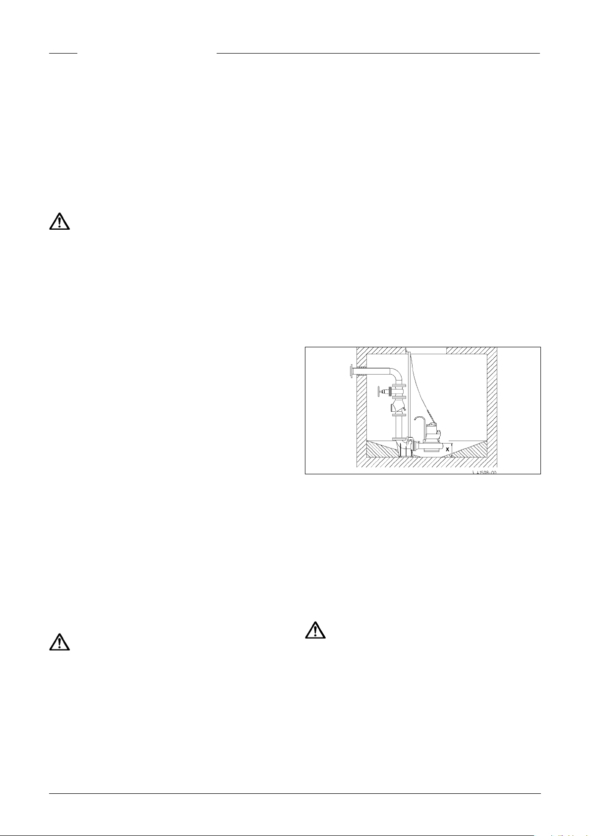
Example installation with guide rail system
Assembly: Fix the coupling base rmly to the oor of the col-
lection chamber using plugs and then mount the guide rails.
Next, install the pressure pipe including the necessary ttings,
such as the non-return valve and shut-off valves.
Finally, t the pump with the screwed-on coupling catch on to
the guide rails and lower it into place using a chain xed to the
shackle.
A xing facility for lifting gear should be provided above the
chamber opening at a sucient height.
Level monitoring can be carried out using various systems.
Their specic characteristics and requirements can be found
in the relevant operating manuals.
WARNING!
In accordance with the explosion protection laws and regulations, JUNG Ex-pumps should never be allowed to run dry or to
operate in "snore" mode.
The pump must switch off when the water level sinks to the
upper edge of the pump housing (x in the illustration), at the
very latest. This shut-down must be implemented via a separate switching circuit. Dry running for servicing or inspection
purposes may only take place outside the potentially explosive
area.
A correspondingly larger diameter pipe should be used for
longer pressure pipelines to avoid pipe friction losses.
Rising pressure pipes must be protected from frost! A chamber cover must be selected that is suitable for the intended use
4
ENGLISH
and has the required load-bearing capacity.
If necessary, the pump housing can be ventilated by unscrew-
ing the "Luft" sealing screw. A ushing pipe, available as an accessory, can be installed to minimise deposits and the forma-
tion of oating layers in the chamber.
If the pump is malfunctioning, part of the contents of the oil
reservoir could escape into the pumping medium.
Not Ex-pumps. If a hose is used as a pressure line, care must
be taken to ensure that for every pumping operation the hose
is completely empty before the pump is submersed. Any residual liquid would obstruct the ventilation of the pump housing
and therefore also hinder the pumping operation.
This situation can also occur if the pump runs dry, pumps down
to a lower lever than that shown in the installation drawing, or
runs in "snore" mode during the daily test run.
In these cases, the pump housing must be ventilated by unscrewing the "Luft" sealing screw.
SERVICING
Maintenance and inspection of this product must be carried
out in accordance with EN 12056-4 and EN 60074-19.
To ensure continued reliability of service, we recommend that
you take out a service contract.
Changing the oil
To ensure operational liability, the rst oil change should be
carried out after 300 operating hours, with further oil changes
carried out after every 1000 operating hours.
If the number of operating hours is very low, an oil change
should still be carried out at least once a year.
If wastewater with strongly abrasive constituents is being
pumped, the oil changes should be carried out at correspondingly shorter intervals.
Use HLP hydraulic mineral oil, viscosity class 22 to 46, e.g. Mobil DTE 22, DTE 24, DTE 25, to replace the oil in the oil reservoir.
The quantity of oil required is 1000 cm³, except for A1 and B1
pumps, which must be lled with 800 cm³.
The oil reservoir may only be lled with the specied quantity
of oil. Overlling will result in the pump being rendered inoper-
able.
Cleaning
To clean the impeller and the spiral housing, simply remove the
4 hexagonal screws and lift the motor unit off the spiral housing
CAUTION!
Worn impellers can have sharp edges.
WARNING!
Before carrying out any works: disconnect the pump and the
controls from the mains and take steps to ensure that it cannot
be emergized again.
WARNING!
Check the mains cable for signs of mechanical and chemical
damage. Damaged or kinked cables must be replaced.
NOTICE! When using a chain to lift the pump, please observe
the relevant national regulations regarding accident prevention. Lifting gear must be checked regularly by an expert in accordance with the legal regulations.
NOTICE! Motors in the Ex-range conform to the "ameproof
enclosures" ignition protection category. Maintenance works
that affect the explosion protection may only be carried out by
authorised specialists or by the manufacturer. When carrying
out repairs, all areas next to ameproof gaps must be checked
for damages and, if necessary, replaced by genuine parts.
Oil check
The drain plug is labelled "Öl". In order to check the mechanical
seal, the oil, including any residue, must be drained from the oil
reservoir and collected in a clean measuring container.
• If the oil is contaminated with water (milky), an oil change
must be carried out. Check again after a further 300 operating hours, but at the very latest after 6 months!
• However, if the oil is contaminated with both water and
pollutants, then not only the oil must be replaced, but the
mechanical seal as well.
For monitoring the oil reservoir, it is also possible to retrot the
electrode of our "DKG" or "DKG-Ex" seal leak control device in
place of the "DKG" sealing screw.
NOTICE! If the wrong screws are unscrewed, the oil will run out
of the oil reservoir.
Tightening torque M
for M 6 M
for M 8 MA = 20 Nm
for M 10 MA = 40 Nm
for M 12 MA = 70 Nm
= 8 Nm
A
for A2 screw materials
A
Checking the pump unit
The housing screws for the pump, and the connecting and xing screws of the installation must be checked to ensure they
are xed securely. They should be tightened if necessary.
If the pump performance decreases, or if increasingly loud
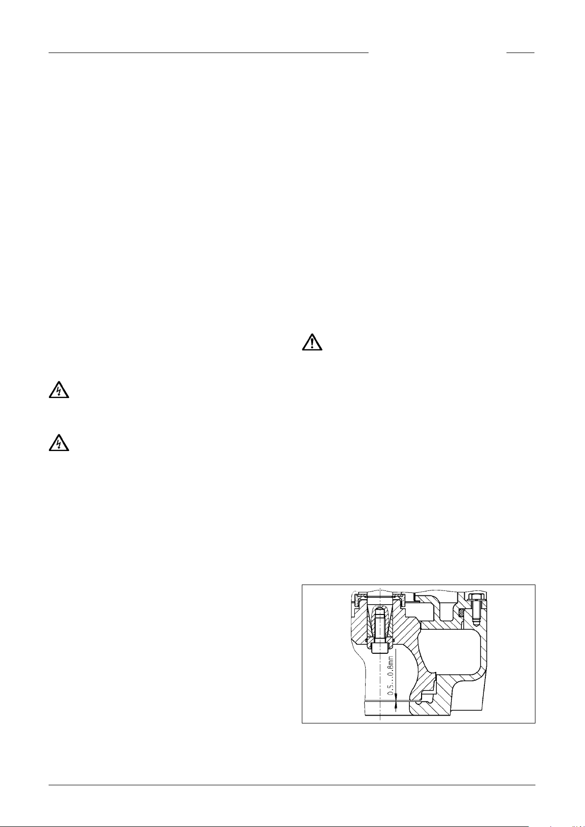
noises can be heard during operation, the gap dimension between the impeller face and the wear plate must be checked
for wear by an expert and replaced if necessary. Nominal dimension: 0.5 - 0.8 mm.
5

ENGLISH
Adjust the impeller gap
1. Block the impeller.
2. Loosen the central impeller screw located in the impeller
hub.
3. Loosen the impeller by knocking it gently with a hammer.
4. Tighten the impeller screw until it is “hand tight”.
5. Adjust the impeller gap by pulling the impeller down to the
nominal dimension 0.5 - 0.8 mm.
6. Block the impeller again and tighten the impeller screw to
65 Nm.
The maximum adjustment possible is 3 mm
Replace the wear plate (...B2, ...B4, ...C1)
1. Loosen the four cylinder head screws on the wear plate on
the lower pump case.
2. Take out the old wear plate with the seal.
3. Clean the wear plate seat and insert the new wear plate with
a new seal.
4. Tighten the four cylinder head screws again.
5. After this, readjust the impeller gap again.
Replacing the impeller
CAUTION!
Worn impellers can have sharp edges.
1. Remove the 4 hexagonal screws and lift the motor unit off
the spiral housing.
2. Block the impeller.
3. Loosen the central impeller screw located in the impeller
hub.
4. Loosen the impeller by knocking it gently with a hammer
and then slide it off the shaft.
5. Clean all the parts of the impeller mounting.
6. Grease the shaft cover on the inside. NOTICE! Do not use
grease containing graphite, such as "Molykote".
7. Fix all the parts of the impeller mounting in place and tighten the impeller screw until it is “hand tight”.
8. Slide the new impeller over the preassembled impeller
mounting onto the shaft.
9. Mount the motor unit on the spiral housing; the cable entry
point is opposite the discharge branch.
10. Set the gap dimension to 0.5 - 0.8 mm and then tighten the
impeller screw to 65 Nm.
WHAT TO DO IN THE EVENT OF
ANY PROBLEMS
Pump does not work
• Check mains current (do not use a pin gauge)
• Fuse faulty = may be too weak (please refer to Electrical
Connection)
• Mains supply cable damaged = repair to be carried out by
manufacturer only
Pump runs but does not pump
• Empty pressure pipe or hose to allow the non-return valve
to open and let the air escape from the pump housing.
• Ventilate the pump housing by unscrewing the "Luft" (air)
sealing screw.
The impeller is blocked
• Solids and brous matter have become lodged in the pump
housing (please refer to Maintenance)
Decreased pumping performance
• The impeller is blocked (please refer to maintenance)
• Rotor gap too large = adjust
• The impeller is worn out = replace it
• Wrong direction of rotation = change 2 phases of the power
supply
6
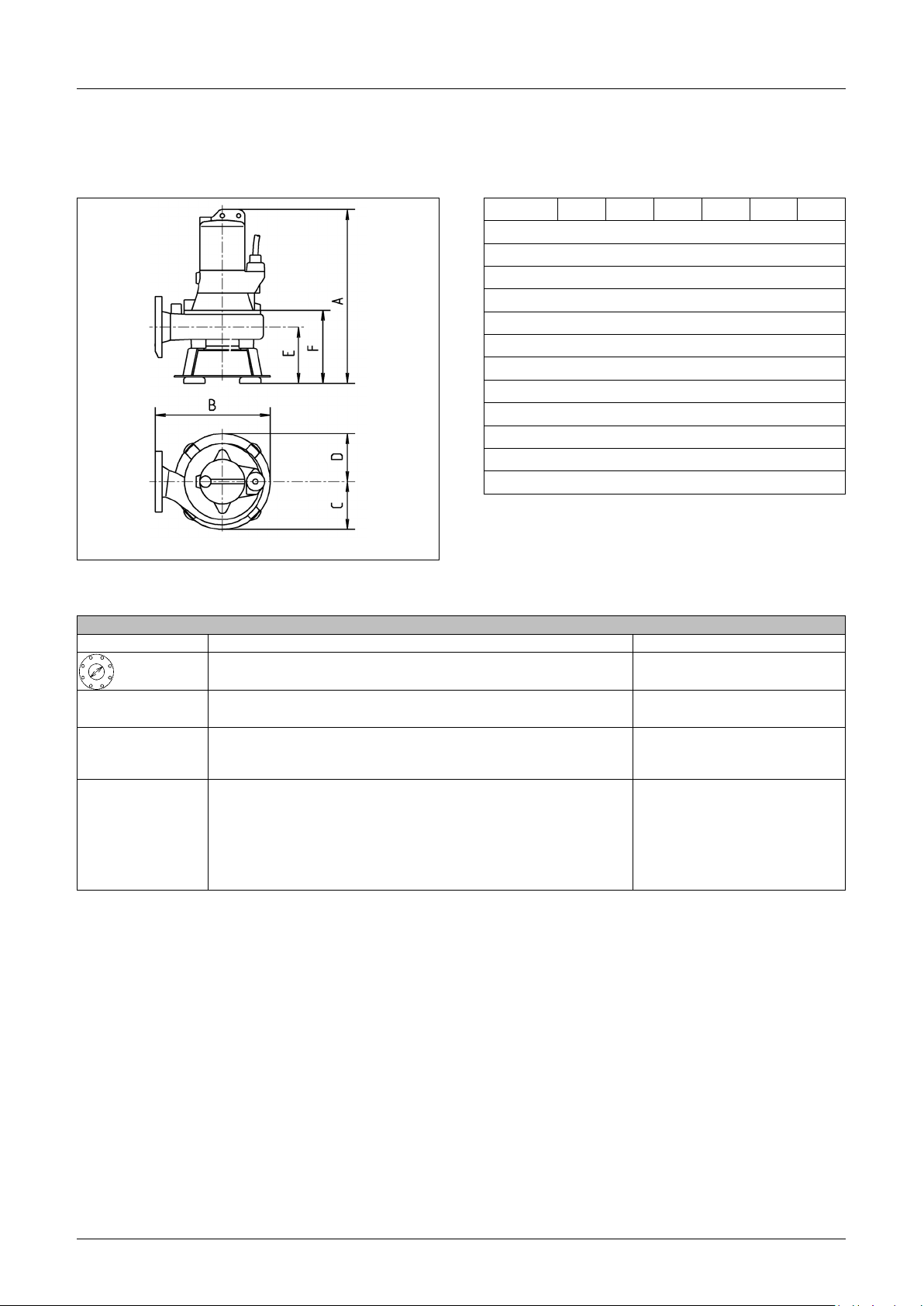
Technische Daten | Technical data | Caractéristiques techniques | Dati tecnici | Technische
gegevens | Dane techniczne | Technické údaje | Technické údaje | Műszaki adatok | Date tehnice
A B C D E F
10/2 A1 475 325 110 105 135 175
15/2 A1 475 325 110 105 135 175
25/2 A2 475 345 135 135 135 185
35/2 A2 510 345 135 135 135 185
25/2 B1 530 340 135 135 185 240
35/2 B2 570 380 145 135 185 240
10/4 B1 530 340 135 135 185 240
15/4 B3 535 380 160 160 185 240
25/4 B4 535 440 190 160 185 240
35/4 B4 570 440 190 160 185 240
25/4 C1 600 450 195 195 235 305
35/4 C1 635 450 195 195 235 305
10/2 A1 15/2 A1 25/2 A2 35/2 A2 25/2 B1 35/2 B2
[kg] 41 42 48 52 45 55
PN 6 /10 DN 65 DN 65 DN 65 DN 65 DN 80 DN 80
[mm] 40 40 40 40 70 70
S2 40 min. 32 min. 26 min. 27 min. 26 min. 27 min.
S3* 60 % 50 % 40 % 40 % 40 % 40 %
EX D 90-2/75 D 90-2/75 D 90-2/75 D 90-2/110 D 90-2/75 D 90-2/110
Motor 08 ATEX 1113 X01 08 ATEX 1113 X01 08 ATEX 1113 X01 08 ATEX 1113 X01 08 ATEX 1113 X01 08 ATEX 1113 X01
II 2 G Ex db IIB T4 Gb Ex db IIB T4 Gb Ex db IIB T4 Gb Ex db IIB T4 Gb Ex db IIB T4 Gb Ex db IIB T4 Gb
P1 / P2 [kW]
U [V]
f [Hz]
I [A]
cos phi
n [min
* Beispiel: 40% = 4 min Betrieb + 6 min Pause (Spieldauer 10 min)
* Example for 40%: 4 min. operation and 6 min. rest (Cycle duration 10 min.)
* Exemple: 40%= 4 min de service et 6 min de pause (Durée du jeu 10 min)
* Esempio: 40%: 4 min. di funzionamento + 6 min. di pausa (durata del ciclo 10 min.)
* Przykładowo 40%: 4 min pracy i 6 min przerwy (Czas cyklu 10 min)
* Příklad 40%: 4 min. provoz a 6 min. přestávka (trvání pracovního cyklu 10 min.)
* Príklad 40%: 4 min prevádzka a 6 min prestávka (doba trvania cyklu 10 min)
* 4 perc üzem és 6 perc szünet (ciklusidő 10 perc)
* Exemplu 40%: 4 min funcţionare şi 6 min pauză (timp aproximativ 10 min)
-1
]
1,3 / 1,1
3/PE x 400
50
2,7
0,72
2900
1,8 / 1,5 2,6 / 2,1 3,7 / 3,2 2,6 / 2,2 3,7 / 3,2
3/PE x 400 3/PE x 400 3/PE x 400 3/PE x 400 3/PE x 400
50 50 50 50 50
3,2 4,4 6,5 4,4 6,5
0,81 0,86 0,83 0,86 0,83
2860 2800 2890 2800 2890
7
10/4 B1 15/4 B3 25/4 B4 35/4 B4 25/4 C1 35/4 C1
[kg] 45 50
PN 6 /10 DN 80 DN 80
[mm] 70 70
S2 45 min. 35 min.
S3* 50 % 40 %
EX D 90-4/ 75 D 90-4/75
Motor 08 ATEX 1113 X01 08 ATEX 1113 X01 08 ATEX 1113 X01 08 ATEX 1113 X01 08 ATEX 1113 X01 08 ATEX 1113 X01
II 2 G Ex db IIB T4 Gb Ex db IIB T4 Gb Ex db IIB T4 Gb Ex db IIB T4 Gb Ex db IIB T4 Gb Ex db IIB T4 Gb
P1 / P2 [kW] 1,0 / 0,8 1,8 / 1,5
U [V] 3/PE x 400 3/PE x 400
f [Hz] 50 50
I [A] 2,3 3,3
cos phi 0,60 0,78
n [min-1] 1440 1385
15/26 A1 25/26 A2 10/46 B1 15/46 B3 25/46 B4
[kg] 41 48 45 50 62
PN 6 /10 DN 65 DN 65 DN 80 DN 80 DN 80
[mm] 40 40 70 70 70
S2 25 min 22 min 40 min 15 min 15 min
S3* 40 % 35 % 45 % 25 % 25 %
Motor D 90-2/75 D D 90-2/110 C D 90-4/75 D D 90-4/75 D D 90-4/110 C
P1 / P2 [kW] 2,7 / 2,1 4,1 / 3,6 1,4 / 1,05 2,7 / 2,0 4,0 / 3,4
U [V] 3/PE x 460 3/PE x 460 3/PE x 460 3/PE x 460 3/PE x 460
f [Hz] 60 60 60 60 60
I [A] 4,1 6,1 2,7 4,0 6,6
cos phi 0,83 0,87 0,65 0,85 0,76
n [min
-1
] 3400 3400 1700 1700 1700
59 62 63 67
DN 80 DN 80 DN 100 DN 100
70 70 100 100
15 min. 16 min. 20 min. 16 min.
25 % 25 % 30 % 25 %
D 90-4/75 D 90-4/110 D 90-4/75 D 90-4/110
2,7 / 2,1 3,5 / 2,65 2,4 / 1,9 3,5 / 2,65
3/PE x 400 3/PE x 400 3/PE x 400 3/PE x 400
50 50 50 50
4,6 6,9 4,2 6,9
0,85 0,74 0,83 0,74
1375 1425 1395 1420
Leistungen • Performance • Puissances • Capaciteit • Prestazioni •
Wydajności i moce • Výkony • Výkony • Teljesítmény • Capacităţi
H [m] 1 2 3 4 5 6 7 8 9 10 12 14 16 18 20 22
10/2 A1 38 35 32 29 26 22 19 16 12 9 3
15/2 A1 50 49 46 43 40 37 35 32 28 25 18 11 5
25/2 A2 62 60 58 56 54 51 48 45 42 39 33 27 20 13
35/2 A2 70 68 67 66 64 63 61 58 56 53 48 43 37 30 24 13
25/2 B1 91 86 80 74 68 61 55 49 42 36 20 8
35/2 B2 126 121 117 111 103 96 89 81 72 65 49 31 16
10/4 B1 59 52 40 28 14 3
15/4 B3 98 90 80 70 58 46 35 20 12 6
25/4 B4 120 114 106 97 87 77 65 53 43 31 9
35/4 B4 132
25/4 C1 154 139 122 103 87 71 51 32 16
35/4 C1 170 160 146 133 119 101 89 71 54 36 3
UC 25/4 C1 104 87 71 51 32 16
UC 35/2 B2 102 95 88 80 72 65 17
UC 35/4 C1 103 89 72 54 36 3
15/26 A1 59 57 55 53 51 48 46 43 41 39 34 28 23 17 12 9
25/26 A2 76 75 74 72 70 68 66 64 62 60 55 50 43 39 34 29
10/46 B1 72 67 60 51 41 30 18 9
15/46 B3 118 112 105 97 88 78 68 59 49 40 21 8
25/46 B4 144 138 132 125 119 112 102 93 84 75 54 34 13
125 119 112 104 95 85 74 64 53 30
Q [m³ /h]
8
MULTISTREAM 10 - 35
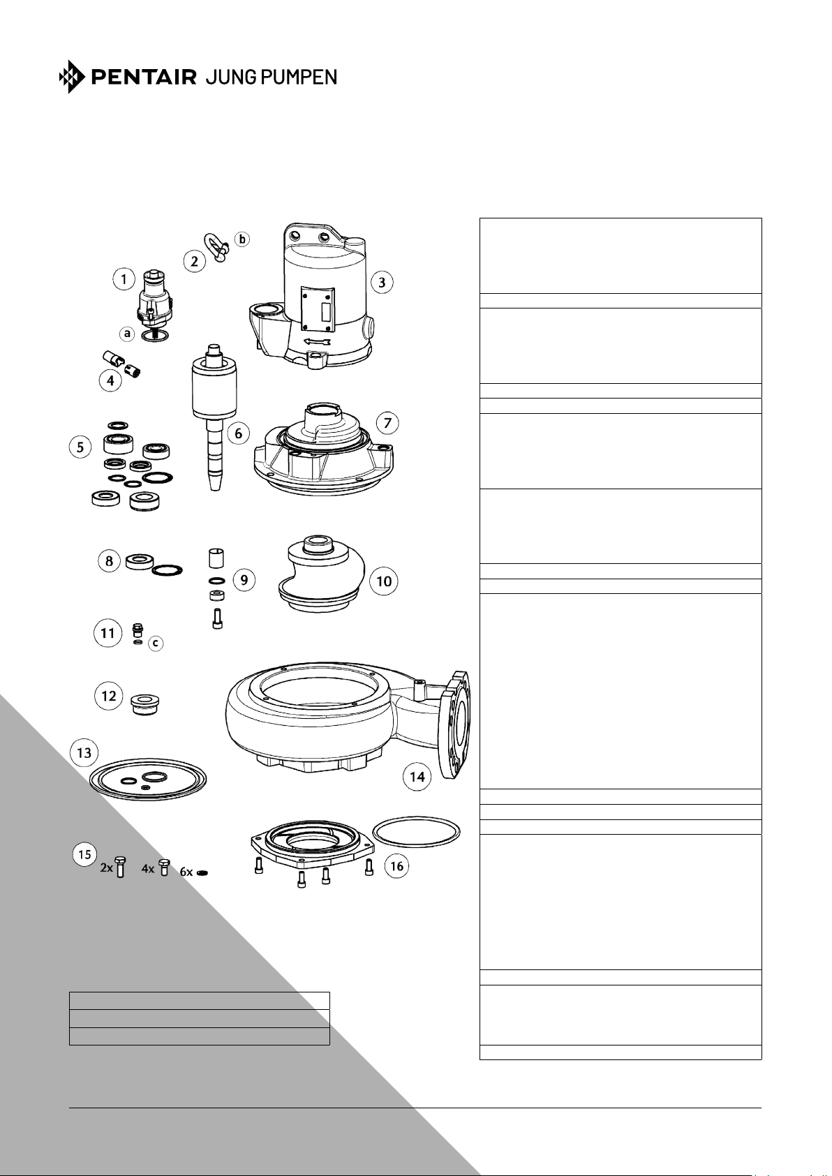
Ersatzteile - Spare parts - Pièces de rechange - Reserveonderdelen - Parti di ricambio - Reservedele - Reserv delar
Varaosat - Części zamienne - Náhradní díly - Alkatrészek - Piese de schimb - Запасные части -
①
Leitung Cable
10 M JP46259
EX, 10 M JP45469
EX, 15 M JP45583
EX, 20 M JP45584
②
Schäkel Shackle
③
Stator + Gehäuse Stator + Housing
10/2, 15/2, 25/2 JP44008
35/2 JP46211
10/4, 15/4, 25/4 JP47042
35/4 JP47045
④
Steckverbinder Connector
⑤
Lagersatz Bearing set
⑥
Rotorwelle Rotor shaft
10/2, 15/2, 25/2 JP47038
35/2 JP47039
10/4, 15/4, 25/4 JP47040
35/4 JP47041
⑦
Lagerkammer Bearing housing
A1 JP47068
B1 JP47069
A2, B2 JP47070
B3, B4, C1 JP47071
⑧
Wellenabdeckung Shaft cover
⑨
Laufradbefestigung Impeller xation
⑩
Laufrad Impeller
10/2 A1 JP47047
15/2 A1 JP47048
25/2 A2 JP47049
35/2 A2 JP47050
25/2 B1 JP47051
35/2 B2 JP47052
10/4 B1 JP47053
15/4 B3 JP47054
25/4 B4 JP47055
35/4 B4 JP47056
25/4 C1 JP47057
35/4 C1 JP47058
⑪
Ölschraube Oil screw
⑫
Gleitringdichtung Mechanical seal
⑬
Dichtungssatz Seal set
⑭
Pumpengehäuse Pump casing
A1 JP47060
A2 JP47061
B1 JP47062
B2 JP47063
B3 JP47064
B4 JP47065
C1 JP47066
UC JP47067
⑮
Schraubensatz Screw set
⑯
a
10x O-Ring 38x3,5
b 10x Splint / Cotter pins 1,6 x 20
O-Ring 10x2,5
c 10x
JP48109
JP46182
JP48088
Schleißring Wear ring
B2 JP47072
B4 JP47073
C1
⑰
1l Öl 1l Oil JP48236
备件
JP45904
JP46572
JP46214
JP47043
JP47059
JP46046
JP46567
JP47077
JP47076
JP47074
JUNG-PUMPEN.DE
9
DEUTSCH ENGLISH
0197
JUNG PUMPEN GmbH - Industriestr. 4-6 - 33803 Steinhagen, Germany
13
411.13.1612
EN 12050-1:2001
Fäkalienhebeanlage
10/2 A1 (JP09615/4)
10/4 B1 (JP09620/4)
15/2 A1 (JP09616/4)
15/4 B3 (JP09622/4)
25/2 A2 (JP09617/4)
25/2 B1 (JP09618/4)
25/4 B4 (JP09623/4)
25/4 C1 (JP09624/4)
35/2 A2 (JP09651/4)
35/2 B2 (JP09652/4)
35/4 B4 (JP09647/4)
35/4 C1 (JP09648/4)
10/2 A1, EX (JP09628/4)
10/4 B1, EX (JP09633/4)
15/2 A1, EX (JP09629/4)
15/4 B3, EX (JP09635/4)
25/2 A2, EX (JP09630/4)
25/2 B1, EX (JP09631/4)
25/4 B4, EX (JP09636/4)
25/4 C1, EX (JP09637/4)
35/2 A2, EX (JP09653/4)
35/2 B2, EX (JP09654/4)
35/4 B4, EX (JP09649/4)
35/4 C1, EX (JP09650/4)
0197
JUNG PUMPEN GmbH - Industriestr. 4-6 - 33803 Steinhagen, Germany
13
411.13.1612
Lifting plant for wastewater containing faecal matter
10/2 A1 (JP09615/4)
10/4 B1 (JP09620/4)
15/2 A1 (JP09616/4)
15/4 B3 (JP09622/4)
25/2 A2 (JP09617/4)
25/2 B1 (JP09618/4)
25/4 B4 (JP09623/4)
25/4 C1 (JP09624/4)
35/2 A2 (JP09651/4)
35/2 B2 (JP09652/4)
35/4 B4 (JP09647/4)
35/4 C1 (JP09648/4)
EN 12050-1:2001
10/2 A1, EX (JP09628/4)
10/4 B1, EX (JP09633/4)
15/2 A1, EX (JP09629/4)
15/4 B3, EX (JP09635/4)
25/2 A2, EX (JP09630/4)
25/2 B1, EX (JP09631/4)
25/4 B4, EX (JP09636/4)
25/4 C1, EX (JP09637/4)
35/2 A2, EX (JP09653/4)
35/2 B2, EX (JP09654/4)
35/4 B4, EX (JP09649/4)
35/4 C1, EX (JP09650/4)
Sammeln und automatisches Heben von fäkalienfreiem und
fäkalienhaltigem Abwasser über die Rückstauebene
BRANDVERHALTEN NPD
WASSERDICHTHEIT Bestanden
WIRKSAMKEIT (HEBEWIRKUNG)
- Förderung von Feststoffen Bestanden
- Rohranschlüsse Bestanden
- Mindestmaße von Lüftungsleitungen NPD
- Mindestießgeschwindigkeit Bestanden
- Freier Mindestdurchgang der Anlage Bestanden
- Mindestnutzvolumen NPD
MECHANISCHE FESTIGKEIT
- Tragfähigkeit und strukturelle Stabilität des Sammelbehälters für die Verwendung außerhalb von Gebäuden
- Strukturelle Stabilität des Sammelbehälters für die Ver-
wendung innerhalb von Gebäuden
GERÄUSCHPEGEL ≤ 70 dB(A)
DAUERHAFTIGKEIT
- der Wasserdichtheit Bestanden
- der Hebewirkung Bestanden
- der mechanischen Festigkeit Bestanden
GEFÄHRLICHE SUBSTANZEN NPD
NPD
NPD
Collection and automatic lifting of wastewater without sewage and
wastewater containing faecal matters above the backow level
REACTION TO FIRE NPD
WATERTIGHTNESS Pass
EFFECTIVENESS (LIFTING EFFECTIVENESS)
- Pumping of solids Pass
- Pipe connections Pass
- Minimum dimensions of ventilating pipes system NPD
- Minimum ow velocity Pass
- Minimum free passage of the plant Pass
-Minimum useful volume NPD
MECHANICAL RESISTANCE
- Load bearing capacity and structural stability of collection tank for use outside buildings
- Structural stability of collection tank for use inside buildings
NOISE LEVEL ≤ 70 dB(A)
DURABILITY
- of structural stability Pass
- of lifting effectiveness Pass
- of mechanical resistance Pass
DANGEROUS SUBSTANCES NPD
NPD
NPD
10
EU-Vaatimustenmukaisuusvakuutus
EU-Vaatimustenmukaisuusvakuutus
EU-Declaraţie de conformitate
EU-Vyhlásenie o zhode
EU-Försäkran om överensstämmelse
RO - Directivă - Norme coroborate
SK - Smernice - Harmonizované normy
SV - Direktiv - Harmoniserade normer
45/2 CW1, EX (JP47353)
45/4 AW2, EX (JP46869)
45/4 BW2, EX (JP46859)
45/4 CW2, EX (JP47237)
25/2 ME, EX (JP09742/4)
35/2 M, EX (JP09807/5)
36/2 M, EX (JP09908/4)
45/2 M, EX (JP09431)
35/2 M Tan, EX (JP09179/3)
36/2 M Tan, EX (JP09180/3)
45/2 M Tan, EX (JP48306)
EU-Déclaration de Conformité
EU-Megfelelöségi nyilatkozat
EU-Dichiarazione di conformità
EU-Conformiteitsverklaring
EU-Deklaracja zgodności
EU-Konformitätserklärung
EU-Prohlášeni o shodě
EU-Overensstemmelseserklæring
EU-Declaration of Conformity
Normes harmonisées
HU - Irányelve - Harmonizá szabványok
IT - Direttive - Norme armonizzate
NL - Richtlnen - Geharmoniseerde normen
PL - Dyrektywy - Normy zharmonizowane
FR - Directives -
DE - Richtlinien - Harmonisierte Normen
CS - Směrnice - Harmonizované normy
DA - Direktiv - Harmoniseret standard
EN - Directives - Harmonised standards
FI - Direktiivi - Yhdenmukaistettu standardi
DE - Bevollmächtigter für technische Dokumentation CS - Oprávněná osoba pro tech-
nickou dokumentaci DA - Autoriseret person for teknisk dokumentation EN - Au-
személy műszaki dokumentáció IT - Persona abilitata per la documentazione tecnica
NL - Bevoegd persoon voor technische documentatie PL - Pełnomocnik ds. dokumentacji
technicznej RO - Persoană autorizată pentru documentatiei tehnice SK - Oprávnená osoba
thorized person for technical documentation FI - Valtuutettu henkilö tekninen do-
kumentaatio FR - Personne autorisée à la documentation technique HU - Hivatalos
www.jung-pumpen.de
25/2 AW1, EX (JP09272)
25/2 BW1, EX (JP09499/1)
25/4 AW2, EX (JP46867)
25/4 BW1, EX (JP09459/1)
25/4 CW1, EX (JP09656/5)
35/2 AW1, EX (JP09152/4)
35/2 BW1, EX (JP09501/1)
35/4 AW2, EX (JP46868)
35/4 BW1, EX (JP09460/1)
35/4 CW1, EX (JP09859/5)
45/2 AW1, EX (JP46870)
45/2 BW1, EX (JP46857)
10/2 AW1, EX (JP47280)
10/4 CW1, EX (JP09609/5)
15/2 AW1, EX (JP47278)
15/4 AW2, EX (JP46792)
15/4 BW1, EX (JP09458/1)
15/4 CW1, EX (JP09611/5)
25/2 AW1, EX (JP09150/4)
25/2 AW1, EX (JP46123)
25/2 AW1, EX (JP46124)
25/2 AW1, EX (JP46119)
25/2 AW1, EX (JP47213)
25/2 AW1, EX (JP46120)
• 2006/42/EG (MD) EN 809:1998/AC:2010, EN ISO 12100:2010
• 2011/65/EU (RoHS)
JUNG PUMPEN GmbH - Industriestr. 4-6 - 33803 Steinhagen - Germany -
• 2014/30/EU (EMC) EN 60034-1:2010, EN 61000-3-2:2014, EN 61000-3-3:2013
• 2014/34/EU (ATEX) EN 60079-0:2011/A11:2013, EN 60079-1:2014
DE - Wir erklären in alleiniger Verantwortung, dass das Produkt den aufgeführten Richtlinien entspricht.
CS - Prohlašujeme na svou výlučnou odpovědnost, že výrobek odpovídá jmenovaným směrnicím.
DA - Vi erklærer under ansvar at produktet i overensstemmelse med de retningslinjer
EN - We hereby declare, under our sole responsibility, that the product is in accordance with the specied Directives.
FI - Me vakuutamme omalla vastuullamme, että tuote täyttää ohjeita.
FR - Nous déclarons sous notre propre responsabilité que le produit répond aux directives.
HU - Kizárólagos felelősségünk tudatában kelentjük, hogy ez a termék megfelel az Európai Unió fentnevezett irányelveinek.
IT - Noi dichiariamo sotto la nostra esclusiva responsabilità che il prodotto è conforme alle direttive citate
NL - W verklaren geheel onder eigen verantwoordelkheid dat het product voldoet aan de gestelde richtlnen.
PL - Z pełną odpowiedzialnością oświadczamy, że produkt odpowiada postanowieniom wymienionych dyrektyw.
RO - Declarăm pe proprie răspundere că produsul corespunde normelor prevăzute de directivele mai sus menţionate.
SK - Na výlučnú zodpovednosť vyhlasujeme, že výrobok spíňa požiadavky uvedených smerníc.
SV - Vi försäkrar att produkten på vårt ansvar är utförd enligt gällande riktlinjer.
10/2 A1, EX (JP09628/4)
10/4 B1, EX (JP09633/4)
15/2 A1, EX (JP09629/4)
15/4 B3, EX (JP09635/4)
25/2 A2, EX (JP09630/4)
25/2 B1, EX (JP09631/4)
25/4 B4, EX (JP09636/4)
25/4 C1, EX (JP09637/4)
45/4 AW2 (JP46795)
45/4 BW2 (JP46858)
45/4 CW2 (JP47236)
25/2 ME (JP09843/4)
35/2 A2, EX (JP09653/4)
35/2 B2, EX (JP09654/4)
35/4 B4, EX (JP09649/4)
35/4 C1, EX (JP09650/4)
DE - Weitere normative Dokumente CS - Jinými normativními dokumenty DA - Andre nor-
35/2 M (JP09806/5)
36/2 M (JP09907/4)
45/2 M (JP09430)
mative dokumenter EN - Other normative documents FI - Muiden normien FR - Autres
documents normatifs HU - Egyéb szabályozó dokumentumokban leírtaknak IT - Altri docu-
menti normativi NL - Verdere normatieve documenten PL - Innymi dokumentami normaty-
wnymi RO - Alte acte normative SK - Iným záväzným dokumentom SV - Vidare normerande
dokument:
EN 60034-5:2001/A1:2007
Steinhagen, 30-08-2018
pre technickú dokumentáciu SV - Auktoriserad person för teknisk dokumentation:
JUNG PUMPEN - Stefan Sirges - Industriestr. 4-6 - 33803 Steinhagen
II 2 G Ex db IIB T4 Gb PTB 08 ATEX 1113 X 01
EN 60079-14:2007
______________________ i.V. ____________________
Physikalisch-Technische Bundesanstalt
Zertizierungssektor Explosionsschutz (0102)
Bundesallee 100 - 38116 Braunschweig - Germany
Stefan Sirges, General Manager Rüdiger Rokohl, Sales Manager
CE 311-16-1808
EU-Declaraţie de conformitate
EU-Vyhlásenie o zhode
EU-Försäkran om överensstämmelse
EU-Déclaration de Conformité
EU-Megfelelöségi nyilatkozat
EU-Dichiarazione di conformità
EU-Conformiteitsverklaring
EU-Deklaracja zgodności
EU-Konformitätserklärung
EU-Prohlášeni o shodě
EU-Overensstemmelseserklæring
EU-Declaration of Conformity
RO - Directivă - Norme coroborate
SK - Smernice - Harmonizované normy
SV - Direktiv - Harmoniserade normer
Normes harmonisées
HU - Irányelve - Harmonizá szabványok
IT - Direttive - Norme armonizzate
NL - Richtlnen - Geharmoniseerde normen
PL - Dyrektywy - Normy zharmonizowane
FR - Directives -
DE - Richtlinien - Harmonisierte Normen
CS - Směrnice - Harmonizované normy
DA - Direktiv - Harmoniseret standard
EN - Directives - Harmonised standards
FI - Direktiivi - Yhdenmukaistettu standardi
www.jung-pumpen.de
• 2006/42/EG (MD) EN 809:1998/AC:2010, EN ISO 12100:2010
• 2011/65/EU (RoHS)
JUNG PUMPEN GmbH - Industriestr. 4-6 - 33803 Steinhagen - Germany -
• 2014/30/EU (EMC) EN 60034-1:2010, EN 61000-3-2:2014, EN 61000-3-3:2013
DE - Wir erklären in alleiniger Verantwortung, dass das Produkt den aufgeführten Richtlinien entspricht.
CS - Prohlašujeme na svou výlučnou odpovědnost, že výrobek odpovídá jmenovaným směrnicím.
DA - Vi erklærer under ansvar at produktet i overensstemmelse med de retningslinjer
EN - We hereby declare, under our sole responsibility, that the product is in accordance with the specied Directives.
FI - Me vakuutamme omalla vastuullamme, että tuote täyttää ohjeita.
FR - Nous déclarons sous notre propre responsabilité que le produit répond aux directives.
HU - Kizárólagos felelősségünk tudatában kelentjük, hogy ez a termék megfelel az Európai Unió fentnevezett irányelveinek.
IT - Noi dichiariamo sotto la nostra esclusiva responsabilità che il prodotto è conforme alle direttive citate
NL - W verklaren geheel onder eigen verantwoordelkheid dat het product voldoet aan de gestelde richtlnen.
PL - Z pełną odpowiedzialnością oświadczamy, że produkt odpowiada postanowieniom wymienionych dyrektyw.
35/2 AW1 (JP09151/4)
35/2 BW1 (JP09500/1)
35/4 AW2 (JP46794)
35/4 BW1 (JP09457/1)
35/4 CW1 (JP09858/5)
45/2 AW1 (JP46796)
45/2 BW1 (JP46856)
45/2 CW1 (JP47352)
DE - Bevollmächtigter für technische Dokumentation CS - Oprávněná osoba pro tech-
nickou dokumentaci DA - Autoriseret person for teknisk dokumentation EN - Au-
személy műszaki dokumentáció IT - Persona abilitata per la documentazione tecnica
NL - Bevoegd persoon voor technische documentatie PL - Pełnomocnik ds. dokumentacji
technicznej RO - Persoană autorizată pentru documentatiei tehnice SK - Oprávnená osoba
thorized person for technical documentation FI - Valtuutettu henkilö tekninen do-
kumentaatio FR - Personne autorisée à la documentation technique HU - Hivatalos
15/4 AW2 (JP46791)
15/4 BW1 (JP09455/1)
15/4 CW1 (JP09612/5)
25/2 AW1 (JP09149/4)
25/2 BW1 (JP09498/1)
25/4 AW2 (JP46793)
25/4 BW1 (JP09456/1)
25/4 CW1 (JP09655/5)
35/2 A2 (JP09651/4)
35/2 B2 (JP09652/4)
35/4 B4 (JP09647/4)
35/4 C1 (JP09648/4)
10/2 AW1 (JP47280)
10/4 CW1 (JP09610/5)
15/2 AW1 (JP47278)
10/2 A1 (JP09615/4)
10/4 B1 (JP09620/4)
15/2 A1 (JP09616/4)
15/4 B3 (JP09622/4)
25/2 A2 (JP09617/4)
25/2 B1 (JP09618/4)
25/4 B4 (JP09623/4)
25/4 C1 (JP09624/4)
RO - Declarăm pe proprie răspundere că produsul corespunde normelor prevăzute de directivele mai sus menţionate.
SK - Na výlučnú zodpovednosť vyhlasujeme, že výrobok spíňa požiadavky uvedených smerníc.
SV - Vi försäkrar att produkten på vårt ansvar är utförd enligt gällande riktlinjer.
DE - Weitere normative Dokumente CS - Jinými normativními dokumenty DA - Andre nor-
mative dokumenter EN - Other normative documents FI - Muiden normien FR - Autres
documents normatifs HU - Egyéb szabályozó dokumentumokban leírtaknak IT - Altri docu-
menti normativi NL - Verdere normatieve documenten PL - Innymi dokumentami normaty-
wnymi RO - Alte acte normative SK - Iným záväzným dokumentom SV - Vidare normerande
dokument:
EN 60034-5:2001/A1:2007
Steinhagen, 30-08-2018
pre technickú dokumentáciu SV - Auktoriserad person för teknisk dokumentation:
JUNG PUMPEN - Stefan Sirges - Industriestr. 4-6 - 33803 Steinhagen
______________________ i.V. ____________________
Stefan Sirges, General Manager Rüdiger Rokohl, Sales Manager
CE 307-16-1808
11
12
13
14
15
16
17
18
19
20

 Loading...