

Pentair MSCI50V20, MSCI50T20, MSCI50V10, MSCI50T50, MSCI50V50 Owner's Manual
...
OWNER’S MANUAL
Submersible Sump Pump
NOTICE D’UTILISATION
Pompe submersibles
pour puisard
MANUAL DEL USUARIO
Bomba sumergibles
para sumideros
Installation/Operation/Parts
For further operating,
installation, or maintenance
assistance:
Call 1-888-987-8677
English ....................... Pages 2-9
Installation/Fonctionnement/Pièces
Pour plus de renseignements
concernant l’utilisation,
l’installation oul’entretien :
Composer le 1 (888) 987-8677
Français ............... Pages 10-17
Instalación/Operación/Piezas
Para mayor información sobre el
funcionamiento, instalación o
mantenimiento de la bomba:
Llame al 1-888-987-8677
Español .................Paginas 18-25
©2016 MY998 (02/03/16)
MSC150 Series

Safety 2
For parts or assistance, call Customer Service at 1-888-987-8677
Important Safety Instructions
SAVE THESE INSTRUCTIONS - This manual
contains important instructions that should be
followed during installation, operation, and
maintenance of the product.
This is the safety alert symbol. When you
see this symbol on your pump or in this manual,
look for one of the following signal words and
be alert to the potential for personal injury!
indicates a hazard which, if not
avoided, will result in death or serious injury.
indicates a hazard which, if not
avoided, could result in death or serious injury.
indicates a hazard which, if not
avoided, could result in minor or moderate injury.
NOTICE addresses practices not related to
personalinjury.
Carefully read and follow all safety instructions
in this manual and on pump.
Keep safety labels in good condition. Replace
missing or damaged safety labels.
General Safety Information
Before you start first, refer to local codes to
ensure safety and regulatory compliance. This
sump pump should give years of trouble-free
service when correctly installed, maintained,
and used. However, interruption of power to
the pump, dirt/debris in the sump, flooding
that exceeds the pump’s capacity, electrical
or mechanical failure in the pump, etc., may
prevent normal pump operation. To help prevent
damage from flooding, purchase a secondary
AC sump pump, a DC backup sump pump,
and/or a high water alarm. See Troubleshooting
in this manual for information about common
sump pump problems and remedies. For more
information, call customer service at 1-888-9878677 or visit our website at femyers.com.
Attention: This owner’s manual contains
important information for the safe use of this
product. Read this manual completely before
using this product and refer to it often for
continued safe product use. DO NOT THROW
AWAY OR LOSE THIS MANUAL. Keep it in a
safe place so that you may refer to it often.
Risk of electric shock. Before
handling these pumps and controls, always
disconnect the power first. Do not smoke or
use spark-able electrical devices or flames in
a septic (gaseous). Can shock, burn or kill. To
reduce the risk of hazardous or fatal electrical
shock, follow instructions A through D, below:
A.
This pump has an approved 3-conductor
power cord with 3-prong, grounding-type plug.
Connect the pump only to a properly grounded,
3-prong outlet. If the sump pump circuit has
a 2-prong outlet, replace it with a grounded
3-prong outlet installed according to code.
B. Unplug the pump before handling or servicing
it. If your basement floor is wet, turn off all
power before walking on it. If the shut-off box
is in the basement, call your electric company
or hydro authority to shut off service to the
house, or call your local fire department
for instructions. After turning off the power,
remove the pump for service.
C. Protect the electrical cords from sharp objects,
hot surfaces, oil, and chemicals. Avoid kinking
the cords. Replace damaged or worn cords.
D. Do not lift the pump by the power cord.
Risk of fire. Plastic pipe glue
is extremely flammable. Follow the glue
manufacturer’s instructions when assembling
glued plastic pipe.
Risk of burns. Motors may run hot.
Allow 20 minutes to cool before handling.
1. Know the pump application, limitations, and
potential hazards.
2. Do not use this pump in water with fish
present. If any oil leaks out of the motor it can
kill fish.
3.
Drain the system completely before servicing it.
4. To prevent a flexible discharge line from
whipping, which could cause injury or
damage, fasten it down before starting
thepump.
5. Before each use, check any hoses in the system
for weakness or wear. Make certain that all
connections are tight.
6. Periodically inspect the sump, the pump,
and the piping for debris and foreign objects.
Perform routine cleaning as required.
7. Personal Safety:
a. Wear safety glasses at all times when
working with pumps.
b. Keep your work area clean, uncluttered
and properly lighted; put away all unused
tools and equipment.
c. Keep visitors at a safe distance from the
workarea.
d. Make workshop child-proof with padlocks
and master switches. Remove any
starterkeys.
8. This pump installation must meet all applicable
laws, codes, and ordinances.
California Proposition 65 Warning
This product and related accessories
contain chemicals known to the State of California to
cause cancer, birth defects or other reproductive harm.
Specifications
Power supply ..........115V, 60 HZ., 15 Amp Circuit
Liquid Temp. Range ..............32°F to 70°F(0°-21°C)
Individual Branch Circuit Required (min.) 15 Amps
Discharge: ................................ 1-1/2” Female NPT
This pump is designed for use in a residential
sump only. Pump water only with this pump.
NOTICE: This unit is not designed as a waterfall
or fountain pump, or for applications involving
salt water or brine! Use with waterfalls,
fountains, salt water or brine will void
warranty.
Do not use where water recirculates.
Not designed for use as a swimming pool
drainer.
NOTICE: Read this owner’s manual for installation,
operation, and safety information.
Tools Required:
Pipe wrench, Strap Wrench, or Slip-Joint Pliers,
Hacksaw,
Screw Driver,
File or Sandpaper
Materials Required:
1-1/2” ABS or PVC Pipe with Cement to match
Threaded Adapter (Pipe to Pump)
Check Valve – Always install a new check valve
when installing a sump pump. If your check
valve does not have an 1/8” anti-airlock hole,
drill one in the discharge pipe
just above where it
screws into the pump discharge
. Be sure to install
the check valve so that the flow will be away
from thepump.
Installation
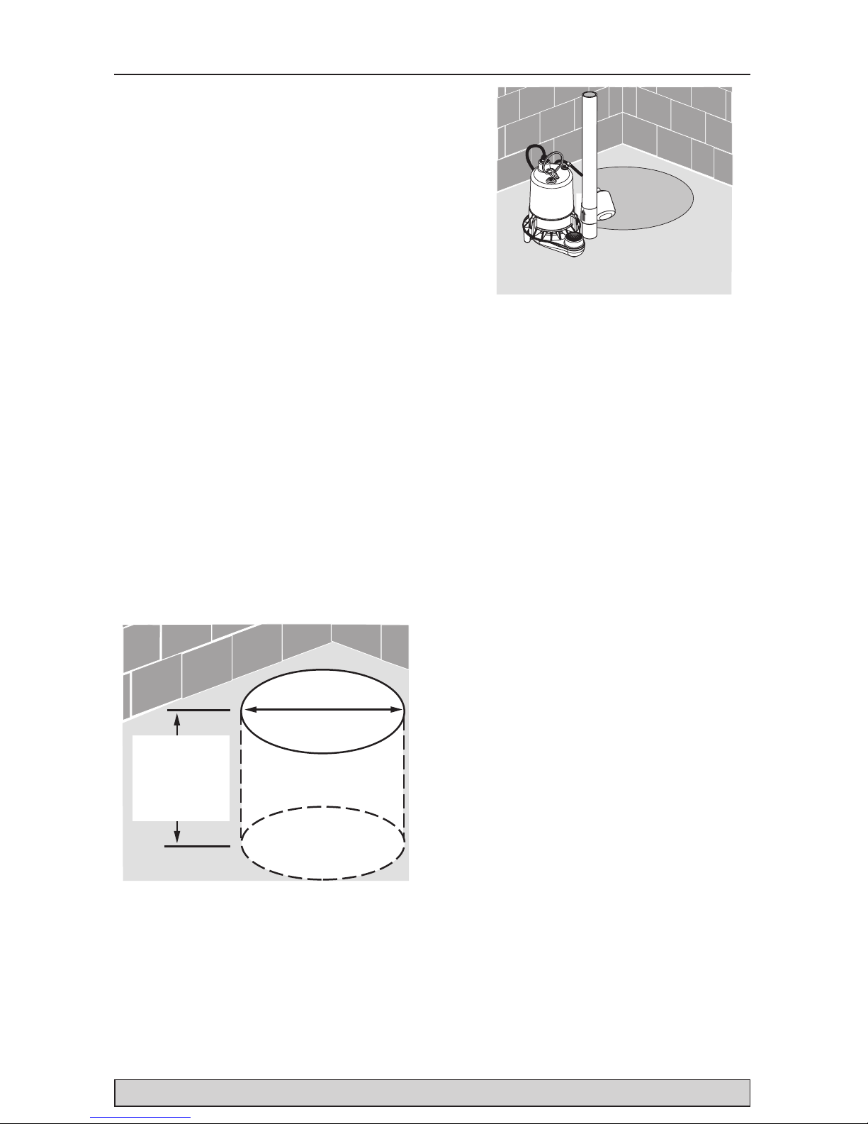
Sump Pit
Hard Surface –
No Sand, Clay,
Gravel
10” Minimum
with Vertical and
Diaphragm Switch
14” Minimum
with Tethered Switch
13” Min. with
Vertical Switch
18” Min. with
Tethered Switch
15” Min. with
Diaphragm Switch
Figure 1
1A. Minimum sump size: 10” (254mm) diameter
by 10” (254mm) depth for vertical and diaphragm
switch models; 14” (356mm) diameter by 18”
(457mm) depth for tethered switch models.
1B. Construct the sump pit of tile, concrete, steel,
or plastic; it must meet code requirements.
1C. No clay, earth, sand, or gravel in the sump
(they will clog the pump). Keep the pump inlet
screen clear.
6201 0410
Figure 2
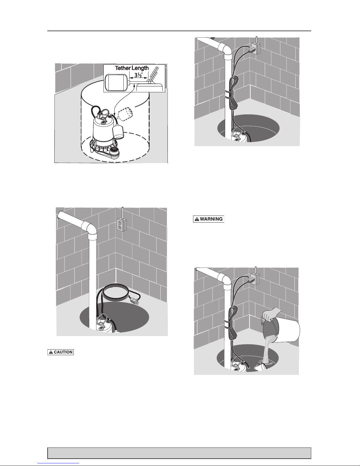
2A. Install the discharge plumbing and check
valve, using PTFE pipe thread sealant tape NOT pipe jointcompound.
2B. Tighten the pipe into the pump (hand tight
+1-1/2 turns).
2C. Install a check valve in the vertical pipe to
prevent flow backwards through the pump
when it shuts off. To prevent airlocking the
pump, drill a 1/8” (3.2 mm) hole in the
discharge pipe just above where it screws into
the pump discharge. Install the check valve
above this hole, but keep it as close to the
pump as possible. Be sure the hole is below
the waterline and below the check valve.
2D. To reduce noise and vibration, cut the
discharge pipe near the pump and fasten
a short length of rubber hose (1-7/8” (48
mm) I.D., e.g. radiator hose) into it with
hoseclamps.
Safety/Installation 3
For parts or assistance, call Customer Service at 1-888-987-8677
Installation 4
For parts or assistance, call Customer Service at 1-888-987-8677
3. Place the pump in the sump; make sure that
nothing interferes with switch operation. For
tethered switch models, the tether length
should be 3-1/2” (See Figure 3).
Figure 3
4. Finish installing the necessary plumbing.
Follow the glue manufacturer’s instructions for
safety precautions and curing time.
Figure 4
Risk of flooding. Make sure the pump
cannot move in the sump. If the pump moves
when it runs, the piping or sump wall may
interfere with the switch and prevent the pump
from starting or stopping.
Figure 5
5. Power Supply: This pump requires a 115 V.,
60 Hz., 15 amp individual branch circuit.
The circuit must be grounded and should
be dedicated to the sump pump. The pump
is supplied with a 3-wire cord set with
grounding-type plug. Plug the switch directly
into the outlet and plug the pump into the
opposite end of the switch’s plug.
Risk of electric shock. Can
shock, burn or kill.
Always ground the pump
to a suitable electrical ground, such as a
grounded water pipe, a properly grounded
metallic raceway, or a ground wire system. Do
not cut off the round ground pin.
Figure 6
6. After you have installed the piping, check
valve, and float switch, the pump is ready for
operation.

Installation/Operation 5
For parts or assistance, call Customer Service at 1-888-987-8677
Check the pump by filling the sump with water
and observing the pump’s operation through
one complete cycle. For switch settings see
Electrical and Switch Specifications.
Risk of flooding.
Failure to make
this operational check may lead to improper
operation, premature failure, and flooding.
Operations
1. The shaft seal depends on water for
lubrication. Do not operate the pump unless
it is submerged in water; running it dry may
damage the seal.
2. If the pump overheats, an automatic-reset
thermal protector cuts off the power and stops
the motor before it can be damaged. The motor
will automatically restart when it cools. If the
protector trips repeatedly, unplug the pump,
remove it from the sump, and check it for
the cause of the difficulty. Low voltage, long
extension cords, clogged impeller, very low lift,
a plugged or frozen discharge pipe, etc., can
all cause cycling and overheating.
3. This pump will not remove all the water in the
sump. If you are running the pump manually
and water stops coming out of the discharge,
the pump has probably run dry. Shut it off
immediately and check the water level.
Performance
GPM At Total Feet Of Lift
Model 5 ft. 10 ft. 15 ft. 20 ft.
No flow at
height shown
below
Capacity Gallons/Min
MSCI50
Series
87 76 63 49 29’
Electrical & Switch Specifications
Model Motor HP
Motor Full
Load Amps
Individual Branch
Circuit Req.
Automatic
Switch Type
*Switch Setting in inches
Water Level For:
On Off
MSCI50V10
1/2 7.7 15A 115VAC
Vertical Switch 7-1/2” 3”
MSCI50V20
MSCI50V50
MSCI50T10
Tethered Switch 13-1/2” 4-1/2”MSCI50T20
MSCI50T50
MSCI50D10
Diaphragm
Switch
9” 4-1/2”
MSCI50D20
MSCI50M20 Non-Automatic Option. No switch included.
Operation/Repair Parts 6
For parts or assistance, call Customer Service at 1-888-987-8677
1
2
4
3
6208 1216
5
6
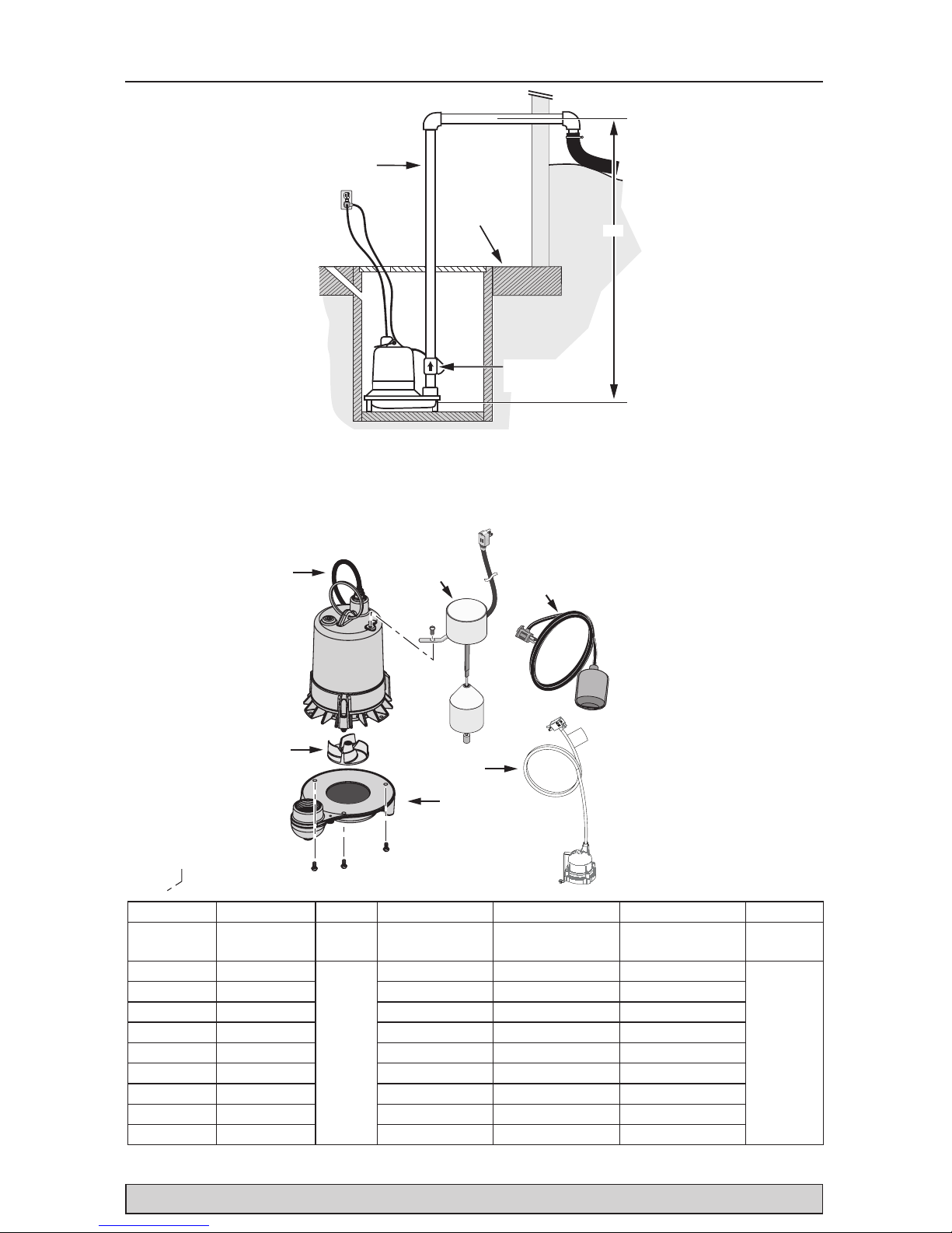
Ref. 1 2 3 4 5 6
Model #
Power Cord
Assembly
Impeller
Tethered Float
Switch
Vertical Float
Switch
Diaphragm Switch Volute
MSCI50V10 PW17-281
PS5-35P
PS17-166
PS1-299G
MSCI50V20 PS17-2121 PS17-167
MSCI50V50 PS17-2122 PS17-2124
MSCI50T10 PW17-281 PS17-91
MSCI50T20 PS17-2121 PS17-93
MSCI50T50 PS17-2122 PS17-2123
MSCI50D10 PW17-281 149740005-01
MSCI50D20 PS17-2121 149740015-01
MSCI50M20 PS17-2121
NOTICE If motor fails, replace entire pump.
† See Page 8 for impeller replacement instructions.
Sump
Pit
Check Valve
(Install Vertically)
Basement
Floor
Discharge
Pipe
Lift
Figure 7 – LIFT: Lift is the vertical distance the
pump actually lifts water. The higher the lift, the
lower the flow.
NOTICE The friction caused by water running
through the pipe will also, on longer pipe runs,
reduce the flow. Pipe smaller than the pump
discharge also reduces flow.
Repair Parts

Troubleshooting 7
For parts or assistance, call Customer Service at 1-888-987-8677
Risk of electrical shock. Unplug the pump before touching it or servicing it.
Symptom Probable Cause(s) Corrective Action
Pump won’t start
or run.
Pump is not plugged in. Make sure the pump is plugged into a proper outlet.
Blown fuse. Replace the fuse with a fuse of proper size.
Low line voltage.
Check the size of the wiring on the circuit feeding the pump and
from the main switch on the property. If everything is OK, contact
your power company or hydro authority.
Defective motor. Replace the pump.
Defective float switch. Replace the float switch.
Clogged or jammed Impeller.
If the impeller won’t turn, unplug the pump, remove the lower
pump body, and locate the source of the binding. Replace the
impeller if necessary.
Pump starts and
stops too often.
Backflow of water from piping. Install or replace the check valve.
Faulty switch. Replace the switch.
Pump won’t
shut off.
Defective switch. Replace the switch, after first checking that switch is functional.
Restricted discharge (obstacle or
ice in the piping).
Unplug the pump, remove it from the sump, and clean the pump
and piping.
Restricted intake screen.
Unplug the pump, remove it from the sump, and clean the intake
screen and impeller.
Pump operates
but delivers little
or no water.
Low line voltage.
If the voltage is below 110 volts, check the size of the wiring
from the main switch on the property. If OK, contact your power
company or hydro authority.
Debris caught in the impeller. Remove the pump and clean out the impeller.
Worn or defective parts or
plugged impeller.
Clean the impeller if it’s plugged; replace the impeller if
necessary; otherwise replace the pump.
Check valve installed without
vent hole
Drill a 1/8” (3mm) dia. hole between the pump discharge and
the check valve (1-2” above the pump discharge and below the
waterline).
Restricted intake screen. Remove the pump and clean out the intake screen.
Check valve is installed either
backward or upside down.
Be sure the check valve is installed correctly (the flow arrow
should point away from the pump).
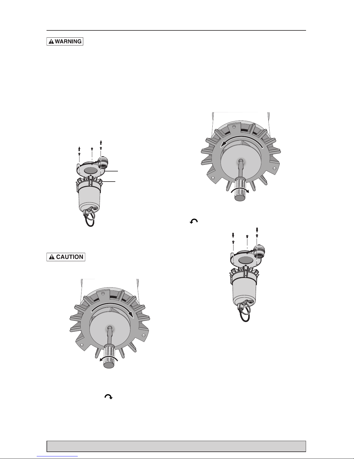
First: Turn off power to the pump, disconnect
the discharge piping, and lift the pump out of
the sump BY THE HANDLE ON TOP OF THE
MOTOR (not by the cord).
Base
Seal Plate
Step 1: A. Invert the pump and secure it from
tipping. B. Remove the three screws holding the
motor to the base and lift the base off the motor.
C. Do not remove the seal plate,
as the motor is full of oil and will spill.
PS5-35P
PS5-35P
Step 2: Hold the motor shaft with a screwdriver
and unscrew the impeller as shown.
NOTICE: The impeller has a left-hand thread, so
it loosens to the right ( ).
Step 3: Thread the new impeller onto the motor
shaft as shown (left-hand thread – tightens to the
left ).
Step 4: Re-mount the base on the motor. Be
sure to mount it so that the switch is clear of the
discharge and all other obstructions in the sump.
Last: Run the pump through one complete cycle
after it is assembled and reinstalled. It should
operate correctly and you should not hear any
sounds of scraping or dragging from the pump.
Impeller Replacement 8
For parts or assistance, call Customer Service at 1-888-987-8677
Risk of electric shock. Can shock,
burn or kill. To reduce the risk of hazardous
or fatal electrical shock, follow instructions A
through B, below:
A. This pump has an approved 3-conductor power
cord with 3-prong, grounding-type plug. Connect
the pump only to a properly grounded, 3-prong
outlet. If the sump pump circuit has a 2-prong
outlet, replace it with a grounded 3-prong outlet
installed according to code.
B. Unplug the pump before handling or servicing
it. If your basement floor is wet, turn off all power
before walking on it. If the shut-off box is in the
basement, call your electric company or hydro
authority to shut off the service to the house, or
call your local fire department for instructions.
After turning off the power, remove the pump for
service.

Warranty 9
For parts or assistance, call Customer Service at 1-888-987-8677
Limited Warranty
Myers® warrants to the original consumer purchaser (“Purchaser” or “You”) of the products listed below, that
they will be free from defects in material and workmanship for the Warranty Period shown below.
Product
Warranty Period
whichever occurs first:
Jet pumps, small centrifugal pumps, submersible pumps
and relatedaccessories
12 months from date of original installation,
or 18 months from date of manufacture
Fibrewound Tanks 5 years from date of original installation
Steel Pressure Tanks 5 years from date of original installation
Sump/Sewage/Effluent Products
12 months from date of original installation,
or 36 months from date of manufacture
Battery Backup Units
MBSP-2, MBSP-2C
MBSP-3, MBSP-3C
12 months from date of original installation,
or 18 months from date of manufacture
24 months from date of original installation,
or 30 months from date of manufacture
Wastewater Solids Handling Pumps
12 months from date of shipment from factory
or 18 months from date of manufacture
Our warranty applies only where such products are used in compliance with the requirements of the applicable
product catalog and/or manuals. For additional information, please refer to the applicable standard limited
warranty featured in the product manual.
Our warranty will not apply to any product that, in our sole judgement, has been subject to negligence,
misapplication, improper installation, or improper maintenance. Without limiting the foregoing, operating a
three phase motor with single phase power through a phase converter will void the warranty. Note also that
three phase motors must be protected by three-leg, ambient compensated, extra-quick trip overload relays of the
recommended size or the warranty is void.
Your only remedy, and MYERS’s only duty, is that MYERS repair or replace defective products (at MYERS’s
choice). You must pay all labor and shipping charges associated with this warranty and must request warranty
service through the installing dealer as soon as a problem is discovered. No request for service will be accepted
if received after the Warranty Period has expired. This warranty is not transferable.
MYERS SHALL NOT BE LIABLE FOR ANY CONSEQUENTIAL, INCIDENTAL, OR CONTINGENT DAMAGES
WHATSOEVER.
THE FOREGOING LIMITED WARRANTIES ARE EXCLUSIVE AND IN LIEU OF ALL OTHER EXPRESS AND
IMPLIED WARRANTIES, INCLUDING BUT NOT LIMITED TO IMPLIED WARRANTIES OF MERCHANTABILITY
AND FITNESS FOR A PARTICULAR PURPOSE. THE FOREGOING LIMITED WARRANTIES SHALL NOT
EXTEND BEYOND THE DURATION PROVIDED HEREIN.
Some states do not allow the exclusion or limitation of incidental or consequential damages or limitations on
the duration of an implied warranty, so the above limitations or exclusions may not apply to You. This warranty
gives You specific legal rights and You may also have other rights which vary from state to state.
This Limited Warranty is effective April 1, 2014 and replaces all undated warranties and warranties dated before
April 1, 2014.
F.E. MYERS
293 Wright Street, Delavan, WI 53115
Phone: 888-987-8677 • Fax: 800-426-9446 • www.femyers.com
In Canada: 490 Pinebush Road, Unit 4, Cambridge, Ontario N1T 0A5
Phone: 800-363-7867 • Fax: 888-606-5484
 Loading...