

Page 1
IntelliTouch ScreenLogic
IntelliTouch ScreenLogic
User’s Guide
User’s Guide
Page 2

© 2006 Pentair Water Pool and Spa, Inc.
1620 Hawkins Ave., Sanford, NC 27330 • (919) 566-8000
10951 West Los Angeles Ave., Moorpark, CA 93021 • (805) 553-5000
All rights reserved. Information in this document is subject to change without notice.
IntelliTouch, IntelliFlo, IntelliBrite, Swimming Colors, MobileTouch, S
Products and the Pentair Water Pool and Spa Inc. logo are registered trademarks of Pentair Water Pool and Spa Inc.
Other trademarks and trade names may be used in this document to refer to either the entities claiming the marks
and names or their products. Pentair Water Pool and Spa disclaims proprietary interest in marks and names of
others.
P/N 520493 - Rev C. 11/27/06
Am, SAL,
and FIBER
works
Pentair Pool
Page 3

Contents
Introduction .............................................................................................. 1
Introduction ............................................................................................................ 1
IntelliTouch System Overview ................................................................................ 1
IntelliTouch System Components .......................................................................... 2
Load or Power Center ........................................................................................... 2
IntelliTouch Personality Kits ................................................................................... 2
IntelliTouch Interfaces ............................................................................................ 3
IntelliTouch ScreenLogic in your home .................................................................. 4
IntelliTouch ScreenLogic Interface Kits .................................................................. 5
IntelliTouch ScreenLogic Interface Accessory Kits ................................................ 5
PDA and Tablet Overview ........................................................................ 7
Personal Digital Assistant (PDA) Description ........................................................ 8
PDA Front and Side Views .................................................................................... 8
PDA Rear View ...................................................................................................... 9
In-Wall Touch Screen .......................................................................................... 10
Tablet Overview ....................................................................................................11
Tablet Controls and Lights .................................................................................... 11
Using your ScreenLogic Interface ....................................................................... 13
Important Precautions (Tablet, PDA, and In-wall Touch Screen) ......................... 13
Cold Boot/Power On-Off/Reset (Tablet and In-wall Touch Screen) ..................... 13
Cold Boot/Power On-Off/Reset (PDA) ................................................................ 13
Save System Settings (Tablet and In-Wall Touch Screen) .................................. 13
Low Battery Condition (Tablet and PDA) ............................................................. 14
Power ON and OFF (Tablet and PDA) ................................................................ 14
Battery and Power Management (Tablet) ............................................................ 14
Battery and Power Management (PDA) .............................................................. 14
i
Installation .............................................................................................. 15
Before You Begin ................................................................................................. 16
Tools Required ..................................................................................................... 16
Connection Steps Summary ............................................................................... 16
ScreenLogic Location Requirements .................................................................. 17
Less walls and ceilings equals better wireless reception .................................... 17
Cable Distance Limits ......................................................................................... 18
Recommended Wireless Router and Protocol adapter Location ........................ 18
Wireless router and Protocol adapter with existing Indoor Control Panel ............ 19
Adding a Wireless Extender Wall-Plug for Large Homes/Properties................... 20
Connecting without Broadband Internet Access .................................................. 21
Connecting to your Home Network with Broadband Access ............................... 22
Connecting to an existing home network ............................................................. 22
Installing the Wireless Extender Wall-Plugs for Large Homes/Properties........... 22
Connect to the Protocol Adapter.......................................................................... 24
Connecting to the Personality Board ................................................................... 25
Start up the IntelliTouch ScreenLogic System for the first time ........................... 27
To start up the system ......................................................................................... 27
IntelliTouch ScreenLogic User’s Guide
Page 4

ii
Contents (Continued)
Configuring ScreenLogic ..................................................................... 29
Accessing IntelliTouch ScreenLogic Configuration Program ............................... 30
Installing IntelliTouch ScreenLogic Software on a PC or Laptop (iTC15 Kit only) 30
Start the Configurator Utility on the Tablet or In-Wall Touch Screen ..................... 30
Start ScreenLogic Program ................................................................................. 31
Start the Configurator Utility on the PDA .............................................................. 31
Exit ScreenLogic Program .................................................................................. 31
Transfer Time from the Configurator Utility .......................................................... 31
Compatibility with IntelliTouch Systems ............................................................... 31
ScreenLogic Configuration and Maintenance Screen ......................................... 32
General Settings (Step 1 of 5) ............................................................................. 32
Changing the Display to Show Fahrenheit to Celsius ......................................... 34
Calibrating Temperature Sensors........................................................................ 34
Setup Circuits (Step 2 of 5) ................................................................................. 35
Special Lights Button ........................................................................................... 36
Feature Circuit Configuration Button ................................................................... 36
Feature Macro Circuits Overview ........................................................................ 37
Freeze Protection ................................................................................................ 37
Assign a Circuit Name and Function ................................................................... 38
IntelliTouch Circuit Functions ............................................................................... 39
IntelliTouch Circuit Names ................................................................................... 40
Creating a Feature Circuit Macro ........................................................................ 41
Creating Custom Names for Auxiliary Circuits .................................................... 42
Display a Circuit Function Button on the Main Screen......................................... 42
IntelliTouch Indoor Control Panel Circuit Names .................................................. 42
Configure Other Equipment (Step 3 of 5) ............................................................ 43
Configuring Valve Actuators (Controlled by AUX or Feature Circuit) .................... 44
Configuring Valve Actuators ................................................................................. 45
Setting up Additional Equipment .......................................................................... 46
Setting up a Two-Speed Pump ............................................................................ 46
Setup Solar Equipment and Heat pump options .................................................. 47
Set a Cool-Down Cycle for the Heater ................................................................ 47
Enable Manual Spa Heat Control ......................................................................... 48
Chlorine Generator .............................................................................................. 48
Activate the Chlorinator Control Interface ............................................................ 48
Configure IntelliFlo (Step 4 of 5)........................................................................... 49
Configure iS10 Spa-Side Remote (Step 5 of 5) ................................................... 53
Configure iS4, iS10, and QT4 QuickTouch .......................................................... 54
IntelliTouch ScreenLogic User’s Guide
Page 5

Contents (Continued)
Using ScreenLogic ................................................................................ 53
Home Screen ...................................................................................................... 56
Main Screen ........................................................................................................ 57
Configuring Pool and Spa Heating System Options ............................................ 59
Change the Pool and Spa Temperature ............................................................... 60
Changing Pool Heat Settings ............................................................................... 60
Changing Spa Heat Settings ................................................................................ 60
Main Lights Screen .............................................................................................. 60
Color Lights Tab ................................................................................................... 61
Dim Lights ........................................................................................................... 62
Special Lighting Features .................................................................................... 63
Lights Screen: Configure Set Colors Tab (Color Set) .......................................... 64
Color Set Lighting Feature ................................................................................... 66
Set up Swimming Colors (Color Swim) .............................................................. 66
Color Sync ........................................................................................................... 67
Switching Lights All on/All off ............................................................................... 67
Lights Screen: IntelliBrite ..................................................................................... 68
Color light show and fixed color buttons .............................................................. 68
Save and Recall buttons...................................................................................... 68
Schedule Screen ................................................................................................. 69
Schedule Feature ................................................................................................ 70
Schedule: Run Once Screen .............................................................................. 71
Run-Once Timer.................................................................................................. 72
Schedule: Egg Timer Screen .............................................................................. 73
Setting the Egg Timer (Count Down)................................................................... 74
History Screen ..................................................................................................... 75
Equipment: System Status Screen ..................................................................... 76
System Error Messages...................................................................................... 77
System Delay Cancel Feature ............................................................................ 77
Enable/Disable Spa-Side Remotes ..................................................................... 77
Chlorinator Status and Controls Screen .............................................................. 78
Equipment: Chlorinator Screen ........................................................................... 78
IntelliFlo Status and IntelliFlo Controls Screen..................................................... 79
Equipment: IntelliFlo Screen ................................................................................ 79
IntelliFlo Status and IntelliFlo 4x160 Controls Screen .......................................... 81
iii
Frequently Asked Questions (FAQs) and Troubleshooting................ 83
ScreenLogic Tips and FAQs................................................................................ 84
ScreenLogic Technical Support Questions ......................................................... 84
Why does the Configuration program say “Looking for Controller”? .................... 84
My ScreenLogic device stopped responding to inputs or is acting strangely. ...... 84
How do I exit the ScreenLogic program while using the
Tablet or In-wall Touch Screen? ........................................................................... 85
ScreenLogic Error Messages .............................................................................. 85
My Tablet or PDA wireless settings have been deleted accidentally,
what do I do? ...................................................................................................... 85
How many ScreenLogic Protocol adapters can I install in an
IntelliTouch system .............................................................................................. 85
IntelliTouch ScreenLogic User’s Guide
Page 6

iv
Contents (Continued)
My Tablet and/or PDA lost the wireless connection to the
ScreenLogic Wireless Router or Range Extender. How do I reconnect?............ 86
I can’t locate the ScreenLogic program on my PDA - How do I install it? ............ 87
PDA First Time Setup Instructions....................................................................... 87
Charging the PDA ................................................................................................ 87
Setting up the PDA for the first time..................................................................... 87
PDA Tips and FAQs ............................................................................................. 89
PDA On/Off Button (Turn off Backlight) ............................................................... 89
How can I calibrate the PDA screen? .................................................................. 89
Starting Up the Tablet ........................................................................................... 89
What is the first thing I should do with the Digital Tablet or PDA? ........................ 89
Why doesn’t the Digital Tablet or PDA come charged so
that I can turn it on right away? ............................................................................ 89
Do I need to load any software to get started? .................................................... 90
Is there anything I should NOT do with the device while
I am learning to use it? ........................................................................................ 90
Is there anything I need to assemble before I turn it on?...................................... 90
How do I begin to use the Digital Tablet and in-Wall Touch
Screen immediately? ........................................................................................... 90
“Connecting Please Wait” message.................................................................... 91
How do I make the panel brighter/darker? ........................................................... 91
How do I switch the Tablet off? ............................................................................ 91
My Digital Tablet will not switch on ....................................................................... 91
My Digital Tablet will not switch off ....................................................................... 91
I changed my mind immediately after recovering from
Suspend mode and wish to put the device into Suspend again.
Why is it that the Suspend button appears nonresponsive? ............................... 91
The Tablet comes with protective rubber grip handles and
a shoulder strap – what do they offer and how do I use them? ........................... 92
The Tablet comes with a desktop cradle – what are its functions? ..................... 92
Cleaning the Touch Screen ................................................................................. 92
IntelliFlo Alarms and Warnings ............................................................................ 93
IntelliFlo 4x160 Alarms and Warnings .................................................................. 94
Appendix ................................................................................................ 95
The wireless router that came with my ScreenLogic kit
does not reliably reach the area where I primarily use
my Tablet and/or PDA .......................................................................................... 96
Range Extender Kit Description .......................................................................... 96
ScreenLogic Wireless Connection Kit ................................................................. 97
Connecting remotely to your system ................................................................... 98
HomeLogic Management and Control Solution ................................................... 99
In-Wall Touch Screen Installation ....................................................................... 100
Glossary ............................................................................................... 102
IntelliTouch ScreenLogic User’s Guide
Page 7
IMPORTANT SAFETY PRECAUTIONS
Important Notice:
Attention Installer: This manual contains important information about the installation, operation and
safe use of this product. This manual should be given to the owner and/or operator of this equipment.
WARNING - Before installing this product, read and follow all warning notices and instructions
which are included. Failure to follow safety warnings and instructions can result in severe injury, death,
or property damage. Call (800) 831-7133 for additional free copies of these instructions.
CAUTION - Danger of explosion if battery is incorrectly replaced. Replace only with the same
type recommended by the manufacturer. Dispose of used batteries according to the manufacturer’s
instructions.
v
Rechargeable Lithium-ion battery disposal
Unwanted lithium ion battery packs may be returned to your local recycling center or the battery
manufacturer for disposal.
Digital and in-wall Tablet and PDA Enclosure
Dismantling or opening the device enclosure or case will void warranty and may possibly cause
electric shock.
CE (EU) Declaration of Conformity
This product conforms to the essential protection requirements of the European Council Directive 89/
336/EEC that relates to electromagnetic compatibility, EN55022:1998, Class B; and EN61000- 3-2, 3-3,
4-2, 4-3, 4-4, 4-5, 4-6, 4-8, and 4-11.
Modifications
The FCC requires the user to be notified that any changes or modifications made to this device that are
not expressly approved by DT Research can invalidate FCC approval.
IntelliTouch ScreenLogic User’s Guide
Page 8

vi
IMPORTANT SAFETY PRECAUTIONS (CONTINUED)
FCC Regulatory Safety Notice - The wireless products devices have been tested and found to
comply with the limits for a Class B digital device, pursuant to Part 15 of the FCC Rules. These limits
are designed to provide reasonable protection against harmful interference in a residential
installation. These devices generates, uses and can radiate radio frequency energy and, if not
installed and used in accordance with the instructions, may cause harmful interference to radio
communications. However, there is no guarantee that interference will not occur in a particular
installation. If this equipment does cause harmful interference to radio or television reception, which
can be determined by turning the equipment off and on, the user is encouraged to try to correct the
interference by one or more of the following measures:
• Reorient or relocate the receiving antenna.
• Increase the separation between the equipment and receiver.
• Connect the equipment into an outlet on a circuit different from that to which the receiver is
connected.
• Consult the dealer or an experienced radio/TV technician for help.
• Modifications not expressly approved by the party responsible for FCC compliance could
void the user’s authority to operate the equipment.
CAUTION: FAILURE TO COMPLY MAY RESULT IN SERIOUS INJURY
Please review the following material carefully. Failure to follow the instructions, or failure to heed the
warnings contained in this manual could lead to serious injury.
Special Battery Cautions:
The following are special precautions you should take when using and handling batteries.
· Do not expose batteries to direct sunlight or extreme heat.
· Do not submerge batteries in liquid.
· Do not incinerate batteries.
· Do not handle damaged or leaking battery packs.
· Do not attempt to discharge batteries by short-circuiting them.
· Do not attempt to charge batteries with a charger other than one approved for use with the Digital
Tablet or PDA.
· Do not leave or operate the Digital Tablet
vehicle under hot sunshine or beside a fire, or heater. Do not leave PDA or Digital Tablet exposed to
excessive heat for any period of time. Excessive heat exposure may result in melting, or cause the
electronics/battery to overheat resulting in fire.
· Use only the supplied batteries and AC Adapter. Failure to follow this instruction may result in battery
burst or liquid leak, and may cause fire, or injury.
or PDA, in an excessively hot environment such as a closed
· Store and Dispose of all batteries in accordance with the instructions contained herein. Never
dispose of the battery by burning. Any such action may result in excessive heating, explosion, or fire.
· Do not disassemble, modify, puncture, or strike any battery with force or allow batteries to become
wet. Any such action may result in excessive heat, explosion, or ignition.
IntelliTouch ScreenLogic User’s Guide
Page 9

IMPORTANT SAFETY PRECAUTIONS (CONTINUED)
CAUTION: Danger of explosion if battery is incorrectly replaced.
• Replace only with the same type recommended by the manufacturer.
• Dispose of used batteries according to the manufacturer’s instructions.
• Rechargeable Lithium-ion battery disposal
• Unwanted lithium ion battery packs may be returned to the battery manufacturer for disposal.
• Enclosure: Dismantling or opening the device enclosure or case will void warranty and
may possibly cause electric shock. Avoid exposure to water.
vii
IntelliTouch ScreenLogic User’s Guide
Page 10

viii
About this User’s Guide
This manual describes the how to set up and use IntelliTouch ScreenLogic, including how to configure your
IntelliTouch system using the Configurator utility, and how to use the ScreenLogic program to control basic
everyday pool and spa operations to advanced setup functions that only need to be performed once.
This manual includes the following sections:
• Introduction (page 1): IntelliTouch system description.
• PDA, In-Wall Touch Screen, and Tablet Overview (page 7): Basic description of control
functions for the PDA, In-wall Touch Screen, and Tablet.
• Installation (page 15): How to install the Protocol adapter and wireless router. Also, location
recommendations.
• Configuring ScreenLogic (page 29): Description of each Configurator utility dialog. Each
dialog description is followed by more detailed information and examples of the features.
• Using ScreenLogic (page 53): Description of ScreenLogic user screens. Each screen
description is followed by more detailed information about how to use ScreenLogic features.
• FAQs and Troubleshooting (page 83): Frequently asked questions about using your Tablet,
PDA and ScreenLogic. Also includes troubleshooting information.
• Appendix (page 95): Tablet specifications and operating information. Also, includes information
about HomeLogic management and control solutions.
• Glossary (page 101): Glossary of terms used in this manual.
Technical Support
Sanford, North Carolina (8 A.M. to 5 P.M.)
Moorpark, California (8 A.M. to 5 P.M.)
Phone: (800) 831-7133
Fax: (800) 284-4151
Web site: visit www.pentairpool.com and www.starite.com
Related IntelliTouch Manuals
IntelliTouch User’s Guide (P/N 520102)
IntelliTouch Personality Kit User’s Guide (P/N 520101)
IntelliTouch Load Center and Power Center User’s Guide (P/N 520100)
IntelliTouch Expansion Kit User’s Guide (P/N 520271)
IntelliTouch ScreenLogic User’s Guide
Page 11

Introduction
Welcome! Your Pentair IntelliTouch ScreenLogic Pool and Spa control system will change the way you view pool
and spa controls. This innovation in pool and spa automation offers complete freedom for you while having full
automation control over your pool, spa, lights, heater, cleaners and much more. You can now schedule multiple start
and stop times to control your lights, heater, spa jets, and filter pumps. The ScreenLogic historical data feature
monitors energy use for your pool, spa and lighting equipment and also records pool, spa, and air temperatures.
This historical data provides a convenient way to help you conserve energy. Using the wireless Digital Tablet or
Personal Digital Assistant (PDA) you can now control your pool and spa from anywhere inside or outside your
home. An in-wall Touch Screen and a program for your PC are also available. IntelliTouch ScreenLogic is a
scalable system that can be upgraded to a completely integrated home automation solution including audio, security,
climate, irrigation and more. For more information about using the ScreenLogic system with the home automation
system by HomeLogic, refer to “HomeLogic Management and Control Solution,” page 100.
This manual describes how to install, configure, and operate the IntelliTouch ScreenLogic system. Before learning
how the IntelliTouch ScreenLogic system works, familiarize yourself with the various wireless and wired controllers
included with each IntelliTouch Personality kit.
IntelliTouch System Overview
1
IntelliTouch systems offer the flexibility to handle from five to 40 circuits that can be used to control any combination
of pumps, lights, water features, etc. As an added benefit, user-configurable circuits can also be used to control
these combinations of features and more. The Feature Macro circuits feature allows any number of circuits to be
combined on a single button. This gives you the ability to set up “themes” with custom names all with a press of a
button. (Not available with IntelliTouch model i5 or i5S).
IntelliTouch users can also dim any high voltage incandescent light such as Pentair Amerlites and SpaBrites up to
eight levels using the IntelliTouch Dimmer Module (P/N 520406). The dimmer module supports multiple lights from
100 watts up to 1,000 watts and installs in a standard relay location. Any number of dimmers (up to 10 maximum)
may be used with a maximum combined load of 4,000 Watts in a single IntelliTouch load center.
In the home
The IntelliTouch system can utilize multiple wired and wireless controllers including the Digital Tablet, Personal
Digital Assistant (PDA), the wired in-wall Touch Screen, Indoor Control Panel, and the wireless MobileTouch
control panel, and even your existing home PC. A maximum of four ScreenLogic interfaces can be used. For
example, four Tablets, or four PDA’s, or four in-wall Touch Screen’s, or four PC’s in any combination.
Around the pool
Located near your spa, the iS10 or iS4 spa-side remote provide control buttons for various pool and spa functions.
The iS10 spa-side remote also provides a temperature display.
At the equipment pad
Near the pump, filter, and other equipment will be located a metal box known as the “load center” or “power
center.” This is where high voltage from the junction box at the home is distributed to the various pool equipment.
The pool service person can periodically check pool operations from this unit. The load center is also where the
various IntelliTouch controllers interface with the other equipment.
Mounted on of top the valves you may also find motorized valve actuators used to change the flow of water through
the plumbing. There may also be temperature sensors and cabling to the heater. There should be no need for anyone
other than your service person to periodically check this equipment.
IntelliTouch ScreenLogic User’s Guide
Page 12

2
IntelliTouch System Components
The main required components of an IntelliTouch system are the Load or Power Center, IntelliTouch Personality
Kits, and the Interfaces:
Load or Power Center
• Load Center: Provides a larger footprint (17" W x 23" H) Includes built-in sub panel (125 AMPS) capable
of holding up to eight 1 inch breakers. Also includes five 25 AMP three HP relays, 110/240 V transformer
with secondary side circuit protection. Multiple knockouts for different sizes of conduit are supplied as well
as a GFCI side knockout. The Load Center provides ample space for all high and low voltage wiring needs.
• Power Center: Offers a smaller footprint (17" W x 17" H) than the Load Center. The Power Center does
not include a circuit breaker base. Users should choose this enclosure if they already have existing circuit
breakers/sub-panel for their equipment.
• Expansion Kits: Models i5X and i10X, offer five or ten additional Auxiliary Circuits for systems i9+3,
i9+3S and i10+3D. Each IntelliTouch Expansion Kit requires a Load Center (P/N 520136) or Power Center
(P/N 520137). Up to three Expansion Kits and Load or Power Centers may be added to a system, for
control of up to 38 Auxiliary Circuits (40 auxiliary circuits for i10+3D).
IntelliTouch Personality Kits
There are several types of IntelliTouch control systems available for different pool/spa configurations:
• Shared Equipment: Pool and spa combinations with shared filtration system – Pool owners can enjoy
the convenience of motorized valves for water flow separation between pool and spa. The Personality Kit
models are:
• i5 (P/N 520505) - Four auxiliary circuits plus filter pump operation. Five relays are included in
the Load Center.
• i7+3 (P/N 520507) - Six auxiliary circuits plus filter pump operation and the +3 option (create a
Feature circuit for valve actuators without using an existing output auxiliary circuit). Two relays
are included in the kit and five in the Load Center.
• i9+3 (P/N 520509) - Eight auxiliary circuits plus filter pump operation and the +3 option (create
a Feature circuit for valve actuators without using an existing output auxiliary circuit). Four relays
are included in the kit and five in the Load Center.
• Dual Equipment: Pool and Spa with Dual Sets of Equipment – The IntelliTouch i10+3D (P/N 520510)
system provides advanced automation for a pool and spa using two separate sets of equipment. This
IntelliTouch Personality Kit controls ten pump and/or lighting circuits and two heaters. The Personality Kit
includes, eight auxiliary circuits plus filter pump operation and the +3 option (create a Feature Macro circuit
for valve actuators without using an existing output auxiliary circuit). Five relays are included in the kit and five
in the Load Center.
• Single Equipment: Pool Only or Spa Only Applications – The IntelliTouch i5S (P/N 520506) and i9+3S
provide advanced automation for a single body of water. The i5S (P/N 520506) Personality Kits includes
four auxiliary circuits plus filter pump operation. There are five relays in the IntelliTouch Load Center. The
i9+3S (P/N 520508) Personality Kits includes eight auxiliary circuits plus filter pump operation and the +3
option (create a Feature Macro circuit for valve actuators without using an existing output aux circuit). Four
relays are included in the kit and five in the Load Center.
IntelliTouch ScreenLogic User’s Guide
Page 13
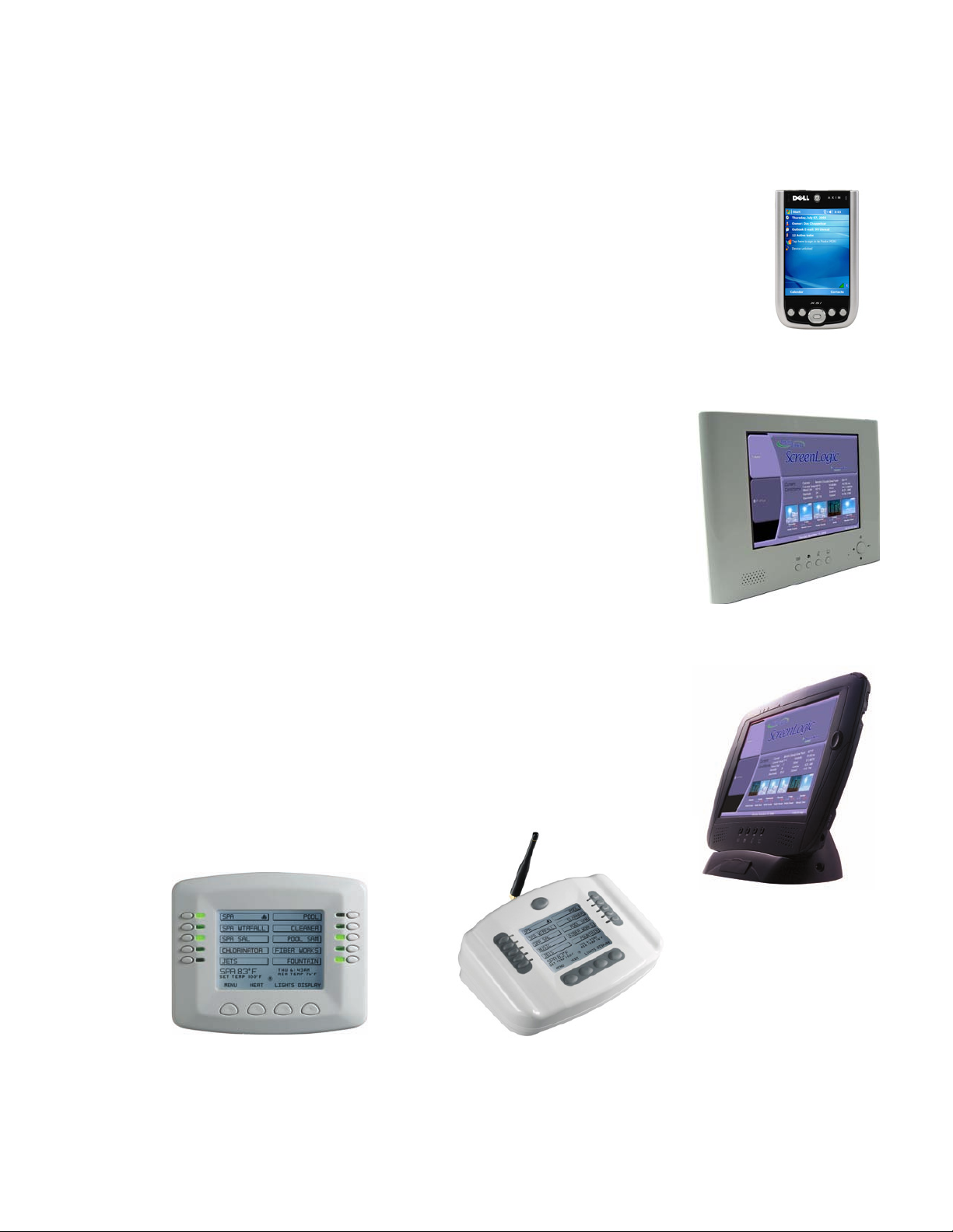
IntelliTouch Interfaces
Pool and Spa owners can choose one or more of the following interface options to control the IntelliTouch system
throughout their home.
• iTC15 Kit (P/N 520500) – Includes Protocol Interface Adapter and wireless router that
connects to existing Desktop or Laptop PC. This allows control of IntelliTouch pool and
spa systems via PC (requires PC with an Ethernet connection, and Windows XP
operating system).
• iTC25 Kit (P/N 520501) – Includes Wireless Personal Digital Assistant (PDA) with
3.5" color touch screen custom configured for IntelliTouch systems, wireless router, and
a Protocol Interface Adapter.
3
• iTC35 Kit (P/N 520502) – Includes in-wall color touch screen with Ethernet
(RJ45) connection and Protocol Interface Adapter and wireless router. The
in-wall Touch screen is custom configured for IntelliTouch systems.
• iTC45 Kit (P/N 520503) – Includes wireless Tablet with color touch screen,
Protocol Interface Adapter, and wireless router. The Tablet is custom
configured for IntelliTouch systems.
• Indoor Control Panel (P/N 520138) – 3.75’’ monochrome backlit LCD
control panel. Connects to Personality board in Load Center.
• MobileTouch (P/N 520340) – 3.75’’ monochrome backlit LCD wireless
control panel with transceiver antenna . Allows any IntelliTouch wired system
to also have a wireless remote with all the capabilities of the Indoor Control
Panel. With an average range of 300 feet, pool owners have system control
anywhere around the home or yard. Powered by a rechargeable lithium-ion
battery. Includes an AC adapter for recharging.
PDA
In-Wall Touch Screen
Indoor Control Panel
Digital Tablet
MobileTouch
IntelliTouch ScreenLogic User’s Guide
Page 14
4
3
1
4
6
2
5
7
8
9
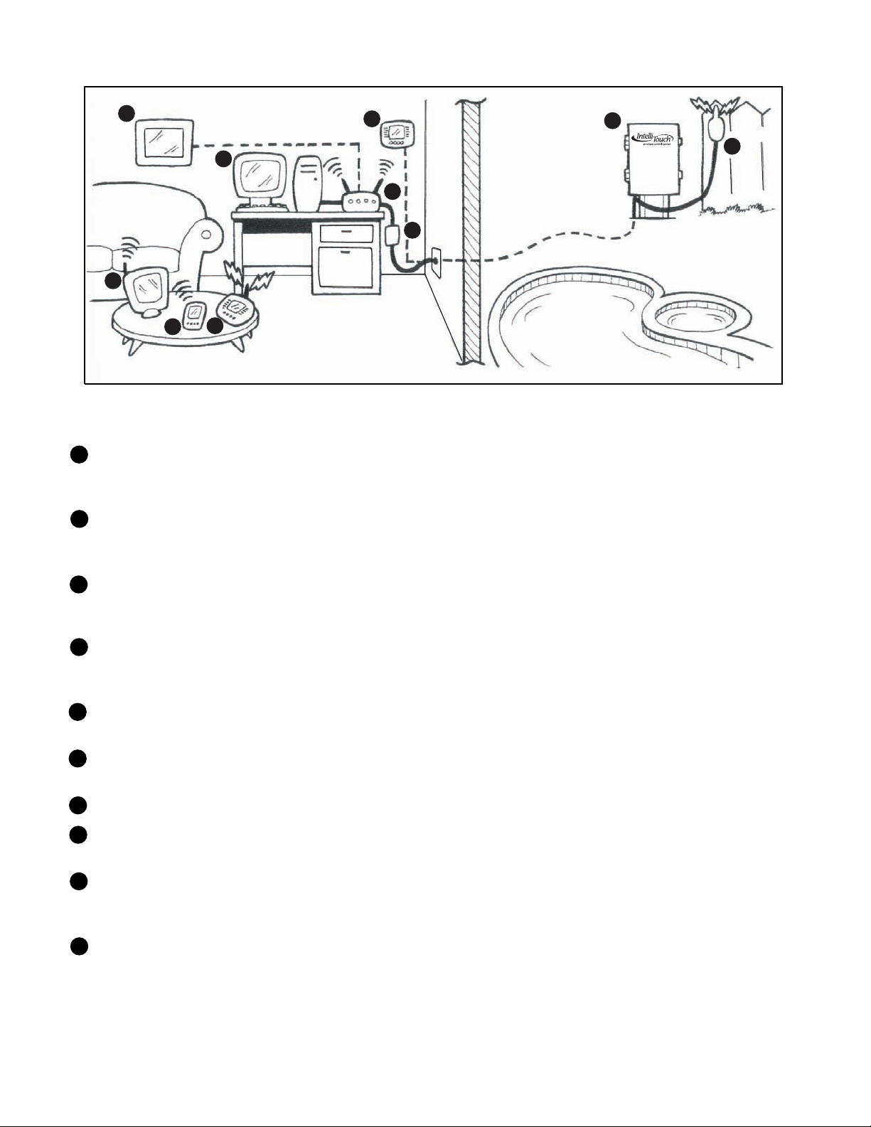
IntelliTouch ScreenLogic in your home
1
Personal Computer (PC): Existing home owner’s PC or Laptop. Connects to a wireless router and the IntelliTouch
Protocol adapter for control of IntelliTouch pool/spa systems. Requires a PC/Laptop (Windows XP) with Ethernet/
RJ45 adapter installed.
2
Personal Digital Assistant (PDA): This wireless PDA with a color touch screen enables you to control your pool
and spa features using the IntelliTouch ScreenLogic interface. The PDA is custom configured for IntelliTouch
systems.
10
In-wall Touch Screen: A color display with Ethernet (RJ45) connector. Connects to the provided wireless router
3
and Protocol adapter via Ethernet (RJ45) for control of IntelliTouch pool and spa systems. The in-wall Touch Screen
is custom configured for IntelliTouch systems.
4
Wireless Tablet: This control panel consists of a color touch screen. Receives and transmits commands via
wireless router and Protocol adapter for control of IntelliTouch pool/spa systems. The Tablet is custom configured
for IntelliTouch systems.
Indoor Control Panel: This control panel consists of a 3.75’’ monochrome backlit LCD and connects to the
5
Personality Board in the Load Center or Power Center for control of IntelliTouch pool and spa systems.
6
MobileTouch: This wireless control panel has a 3.75’’ monochrome backlit LCD. Receives and transmits
commands via the Transceiver antenna located at the Load or Power Center.
7
Wireless router: Connects to the PC or Laptop via Ethernet connection to the Protocol adapter.
8
Protocol adapter: Connects to wireless router via Ethernet connection and to Personality board (Load/Power
Center) via a four-wire 22-AWG cable.
9
Load Center or Power Center. The main control center. Includes the Outdoor Control Panel that controls pump,
heater, and light relays. Receives commands via Protocol adapter, and wireless and wired control panels
connected to the Personality board.
10
MobileTouch Transceiver antenna: This antenna is connected to the Personality board. Sends and receives
commands to and from the MobileTouch control panel.
Note: For IntelliTouch ScreenLogic connection details, refer to page 21 and 22.
IntelliTouch ScreenLogic User’s Guide
Page 15

IntelliTouch Interface ScreenLogic Kits
The following items are included in your IntelliTouch Interface ScreenLogic Kit. As you unpack your IntelliTouch
ScreenLogic Kit, please check to make sure that you received the items listed below. If any item is missing or
damaged, contact your authorized dealer, or contact Technical Support (see page viii).
PC Interface (iTC15 Kit - P/N 520500)
• Protocol adapter.
• Wireless router (802.11b/g) with AC adapter.
• IntelliTouch ScreenLogic User’s Guide (this manual).
• CD-ROM containing IntelliTouch ScreenLogic PC user interface software.
Personal Digital Assistant (PDA) (iTC25 Kit - P/N 520501) - see page 8
• Personal Digital Assistant (PDA) with built-in Wi-Fi 802.11b wireless LAN adapter with antenna. Refer to the
manufacturers documentation for kit contents.
• Wireless router (802.11b/g) with AC adapter.
• Protocol adapter.
• IntelliTouch ScreenLogic User’s Guide (this manual).
• CD-ROM containing IntelliTouch ScreenLogic PC user interface software.
5
In-Wall Touch Screen (iTC35 Kit - P/N 520502) - see page 10
• In-wall Touch Screen, Cradle, and AC adapter.
• Wireless router (802.11b/g) with AC adapter.
• Protocol adapter.
• IntelliTouch ScreenLogic User’s Guide (this manual).
• CD-ROM containing IntelliTouch ScreenLogic PC user interface software.
Digital Wireless Tablet (iTC45 Kit - P/N 520503) - see page 11
• Digital Tablet (with internal battery pack), stylus, built-in Wi-Fi 802.11b wireless LAN adapter with antenna.
• Wireless router (802.11b/g) with AC adapter.
• Protocol adapter.
• IntelliTouch ScreenLogic User’s Guide (this manual).
• CD-ROM containing IntelliTouch ScreenLogic PC user interface software.
IntelliTouch ScreenLogic Interface Accessory Kits
Up to a total of four ScreenLogic interfaces can be used with an IntelliTouch system. If you need additional
interfaces, first order one of the ScreenLogic interface kits listed above, then order one or more of the following
accessory interfaces accessory kits:
• PDA, CD-ROM and manual (P/N 520497)
• In-Wall Touch Screen, CD-ROM and manual (P/N 520498)
• Tablet, CD-ROM and manual (P/N 520499)
Note: The above Accessory Kits interfaces do not include a Protocol adapter or wireless router.
IntelliTouch ScreenLogic User’s Guide
Page 16

6
Blank Page
IntelliTouch ScreenLogic User’s Guide
Page 17
PDA, in-Wall Touch Screen
and Tablet Overview
7
IntelliTouch ScreenLogic User’s Guide
Page 18
8
Personal Digital Assistant (PDA) Description
The iTC25 (P/N 520501) Interface Kit includes a wireless touch screen PDA which is custom configured with the
IntelliTouch ScreenLogic Pool and Spa control application. This device also offers a wide range of capabilities. For
more detailed information about the PDA, refer to the manufacturers documentation shipped with the device.
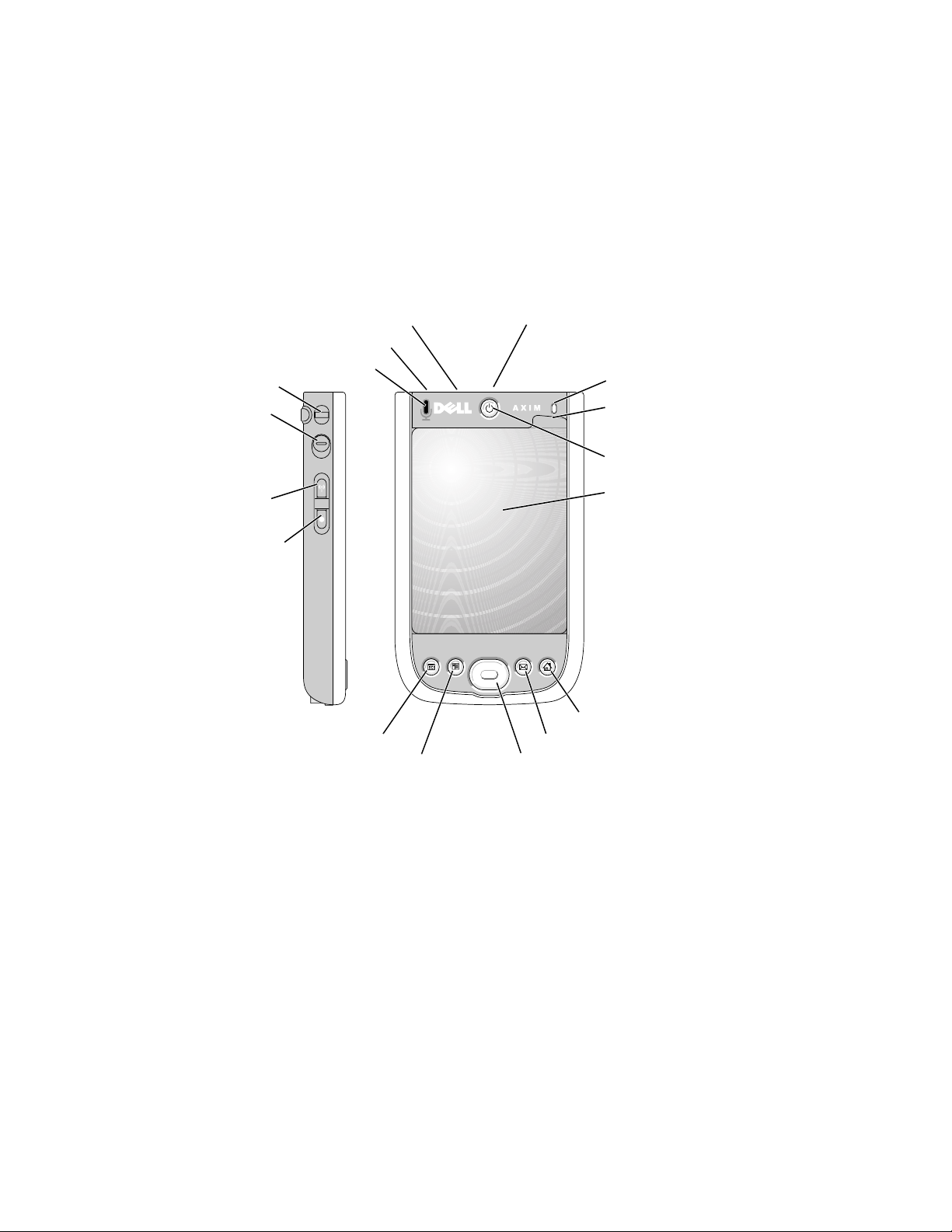
PDA Front and Side Views
The following describes the PDA controls and functions:
infrared sensor (top)
audio connector (top)
lanyard hook
lock button
on/off button for
WLAN/Bluetooth
wireless
technology
record button
Calendar button
microphone
Contacts button
CompactFlash card and
Secure Digital memory card
slots (top)
wireless light
mylar
protector tab
power button
touch screen
Home button
Inbox button
Navigator button
Infrared Sensor: The infrared sensor lets you transfer files from your device to another infrared-compatible
device without using cable connections. Not used by IntelliTouch ScreenLogic.
Microphone: Use to record audio. Not used by IntelliTouch ScreenLogic.
CompactFlash and Secure Digital Memory Card Slots: Not used by IntelliTouch ScreenLogic.
Wireless Light: Illuminates when transmitting and receiving data.
Stylus: Use the stylus to write or draw on the screen. To remove the stylus, pull it straight up and out of the
holder. To avoid losing the stylus, store the stylus in the holder when you are not using it. Ensure that the stylus
is oriented correctly when you replace it in the slot.
IntelliTouch ScreenLogic User’s Guide
Page 19
PDA Front and Side Views (Continued)
Power Button: Press the power button to turn the device on or off. Press and hold the power button to dim the
display. Repeat to light the display.
• When the device is connected to external power and the main battery is fully charged, the power
button light is solid green.
• When the battery charge is low, the power button light flashes amber.
• When the battery is being charged, the power button light is solid amber.
• When the device relays a notification, the power button light rapidly flashes green.
Touch Screen: Use the touch screen and the stylus to enter information into your device.
On/Off Button for WAN/Bluetooth® wireless technology: This button turns the wireless device on and off.
Tap it twice to confirm the switching off or on of WLAN/Bluetooth. Bluetooth is not used by IntelliTouch
ScreenLogic. Switch off the wireless device to conserve power.
Current wireless status Switch Change wireless status
WLAN Bluetooth WLAN Bluetooth
Off Off On On
On Off Off Off
Off On Off Off
On On Off Off
9
Home Button: Press this button to launch the Home window or to turn on the device.
Navigator Button: Press the right, left, top, or bottom of the navigator button to move the cursor on the screen.
Press the center to enter a selection.
Contacts Button: Press this button to launch Contacts or to turn on the device.
Calendar Button: Press this button to launch Calendar or to turn on the device.
Record Button: Press this button to start recording audio.
Lock Button: Use lock the device, keys and touch screen.
Stylus
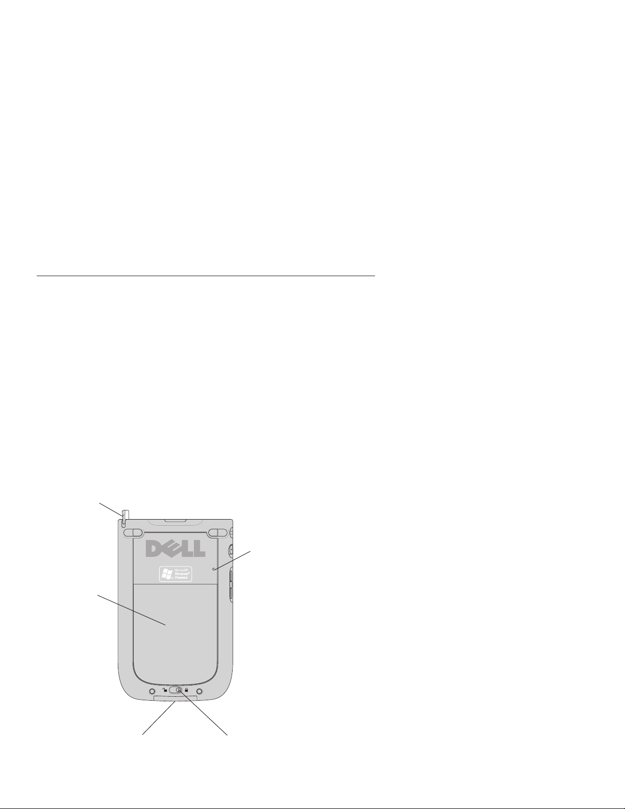
PDA Rear View
Reset
button
Battery cover
(inside)
Battery Lock: Use this switch to release and remove the
battery.
Battery cover: Battery cover.
Cradle/Sync/Cable Connector: Connect a cradle or sync
cable.
Reset Button: Reboots the PDA.
Cradle/Sync and
Cable Connector
Battery lock
IntelliTouch ScreenLogic User’s Guide
Page 20
10
In-Wall Touch Screen
The iTC35 (P/N 520502) Interface Kit includes an in-wall color touch screen which is custom configured with the
IntelliTouch ScreenLogic Pool and Spa control application. The operating software is Windows CE .NET bringing
with it numerous applications, including support for Internet browsing, Windows Media Player, local e-mail client,
and word processing. For in-wall touch screen installation instructions, see “In-Wall Touch Screen Installation,”
page 97.
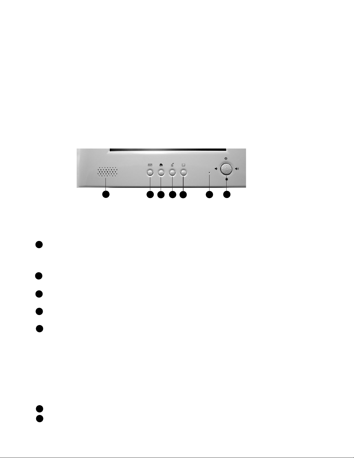
In-Wall Touch Screen Controls
The following describes the in-wall Touch Screen controls:
7
1
3
2
4
6
5
In-Wall Touch Screen (Controls)
1
Virtual Keyboard Toggle Button: Open and close virtual keyboard. To input text into the Digital Tablet,
press this button to display the virtual keyboard. Tap the desired letters to enter text. Press the button
again to close the keyboard. Note: Tap the Ctrl key, then the Q key to exit the IntelliTouch ScreenLogic
program. Double-tap the IntelliTouch ScreenLogic icon on the Windows Desktop to restart the program.
2
Cradle USB (ActiveSync) interface: Enable. Push to Enable USB (ActiveSync) link between PC and
Cradle with device secure on Cradle. Not used by IntelliTouch ScreenLogic program.
3
Launches Internet Explorer Browser: Only works if you are connected to a Broadband Internet
connection.
4
Minimize: Desktop Minimize current application and return to Desktop. Does not work when IntelliTouch
ScreenLogic is running.
5
Center Button - Suspend or Power/Reset:
• Quick push enters or exits Suspend Mode
• Push and Hold to Power Off device (hold for about four seconds until display goes off); then Push to
restart and complete (Cold) Boot process. (Only required if Tablet stops responding).
Navigation buttons:
Volume Down: Push on left edge of button.
Volume Up: Push on right edge of button.
Brightness Up: Push on upper edge of button.
Brightness Down: Push on lower edge of button.
Microphone: Microphone opening. Does not work when IntelliTouch ScreenLogic is running.
6
7
Mono Speaker: Mono speaker opening. Does not work when IntelliTouch ScreenLogic is running.
IntelliTouch ScreenLogic User’s Guide
Page 21
Tablet Overview
The iTC45 (P/N 520503) Interface Kit includes a wireless touch screen Tablet which is custom configured with the
IntelliTouch ScreenLogic Pool and Spa control application. Featuring a robust magnesium alloy enclosure, the
2 lb tablet with 8.4 in TFT display is powered by the Intel XScale processor providing “instant-on” capability with
extended use between battery recharge. The operating software is Windows CE .NET bringing with it numerous
applications, including support for Internet browsing, Windows Media Player, local e-mail client, and word
processing.
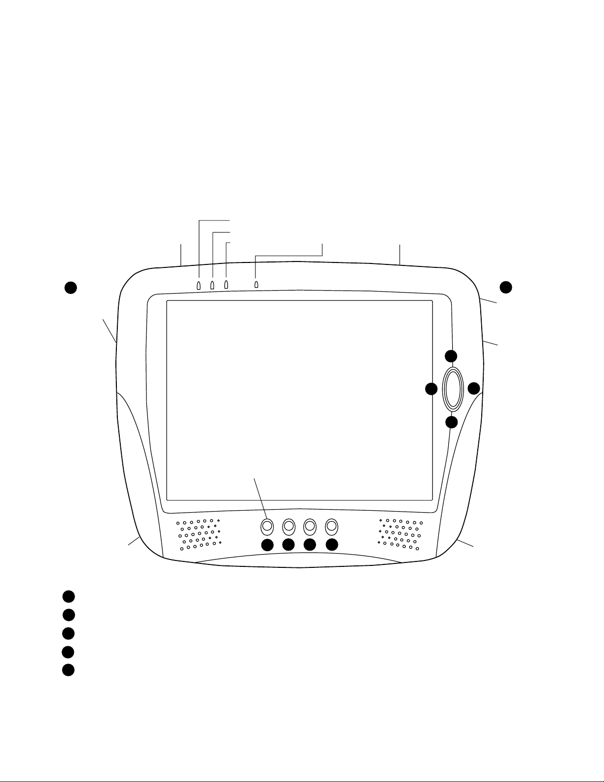
Tablet Controls and Lights
The following describes the Tablet controls and lights:
Record Light
PC Card Slot
Network Light
Battery Light
Microphone
CF Card Slot
11
9
Power/Reset
or Suspend
USB Port (Host)
Note: Press button 5 to display the virtual keyboard.
Tap the Ctrl key, then the Q key to exit the
ScreenLogic program.
6 7 8
5
10
Record
button
(Disabled)
Headphone
3
1
4
Jack
2
Power DC Input
Cradle Interface
1
Volume Down: Push on left edge of oval button.
2
Volume Up: Push on right edge of oval button.
3
Brightness Up: Push on upper edge of oval button.
Brightness Down: Push on lower edge of oval button.
4
5
Virtual Keyboard Toggle Button: Open and close virtual keyboard. To input text into the Digital Tablet,
press this button to display the virtual keyboard. Tap the desired letters to enter text. Press the button
again to close the keyboard. Note: Tap the Ctrl key, then the Q key to exit the IntelliTouch ScreenLogic
program. Double-tap the IntelliTouch ScreenLogic icon on the Windows Desktop to restart the program.
IntelliTouch ScreenLogic User’s Guide
Page 22

12
Button Description Default Action
Tablet Functions (Continued)
6
Cradle USB (ActiveSync) interface: Push to Enable USB (ActiveSync) link between PC and Cradle with
device secure on Cradle. Not used by IntelliTouch ScreenLogic program.
7
Launches Internet Explorer Browser: Only works if you are connected to a Broadband Internet
connection.
8
Minimize: Desktop Minimize current application and return to Desktop. Does not work when IntelliTouch
ScreenLogic is running.
9
Suspend or Power/Reset:
• Quick Push enters or exits Suspend Mode
• Push and Hold to Power Off device (hold for about four seconds until display goes off); then Push to
restart and complete (Cold) Boot process. (Only required if Tablet stops responding)
Record (Right-Edge) Button: Not used by IntelliTouch ScreenLogic.
10
Tablet Lights
There are three lights (LEDs) on the Tablet:
• Record LED: The record LED (left LED) is accessible by applications. A green LED indicates that the
Digital Tablet is recording from its internal microphone.
• Network LED: When the network LED (middle LED) is solid green it indicates that the network adapter is
detected and functional.
• Battery LED: When the battery LED (right LED) is solid green, it means that the batteries are fully charged.
When it is blinking amber, it indicates that the battery is charging. This will only happen when the Digital
Tablet is plugged into the AC power. In the absence of AC power, the steady green state indicates a full or
good battery level; when the battery charge is low, it will glow a steady amber; when the battery level is
critically low, it will blink in amber rapidly.
IntelliTouch ScreenLogic User’s Guide
Page 23

Using your ScreenLogic Interface
Please read the following important information before operating your ScreenLogic interface.
Important Precautions (Tablet, PDA, and In-wall Touch Screen)
Before you use this device, please read this manual for setup procedures, safety precautions, and other important
information. Please review the contents even if you are an experienced user. If you have any problems, contact
Technical Support. For Technical Support contact information refer to page viii.
• The Digital Tablet and PDA must be used and stored inside.
• Keep the Digital Tablet, PDA, and in-Wall touch screen dry. Do not expose the device to moisture.
• Always exercise care when operating and handling the Digital Tablet, PDA, and in-wall touch screen.
• Do not apply excessive pressure to the display screen.
• Avoid exposing the panel screen to direct sunlight or other heat source for an extended period of time.
Where possible, the Tablet and PDA should be facing away from direct lighting to reduce glare.
• If the AC adapter is used to recharge or power the device, DO NOT use any AC adapter other than the one
provided with the device or acquired from the manufacturer or its distributors.
13
• Never attempt to disassemble the Digital Tablet, PDA, or in-wall touch screen. You will lose any product
warranty on the product.
Cold Boot/Power On-Off/Reset (Tablet and In-Wall Touch Screen)
You may use the Suspend Button to cold-boot or Restart the Digital Tablet in the unlikely event of device lockup.
To execute, hold the button for over four seconds to “Power Off” the device. The device will be turned off. This
Reset/Power Off will clear your software settings and data if they are not properly saved to flash memory (see
“Save Tablet System Settings” below). Push again on Suspend Button for a brief moment to restart/reboot the
device. To cold-boot or restart the in-wall touch screen, press and hold for four-seconds the round four-way
directional button on the front of the in-wall touch screen.
Cold Boot/Power On-Off/Reset (PDA)
Insert the stylus into the reset hole on the back of the PDA to cold-boot or reset. (Only required if the PDA stops
responding or has wireless connection problems.)
Save System Settings (Tablet and In-Wall Touch Screen)
Make sure to save your system registries settings in flash memory in the event of a Reset/Power Off. Your system
settings such as date, time, screen brightness can be saved in flash memory.
To save your settings do the following:
1. Tap Start > Settings > Control Panel > Registries Save/Restore.
2. Tap the Save Current Settings check box.
3. Tap OK in Message dialog, to save your settings into persistent storage.
4. Tap OK again to confirm.
5. Tap OK to exit.
IntelliTouch ScreenLogic User’s Guide
Page 24

14
Low Battery Condition (Tablet and PDA)
A warning message will be generated during a low battery condition and the Tablet and PDA will shortly thereafter
be placed into (Forced) Suspend mode if operation continues without external supply of power.
When a low battery condition occurs, the PDA will notify you that its battery is low, then it will automatically turn
off the wireless radio to conserve battery life. Please recharge the PDA and re-enable its wireless radio by pressing
the wireless On/Off button (see page 8).
After the Digital Tablet enters the (Forced) Suspend mode due to the Low Battery condition:
• If over two to four hours elapse without using the AC adapter or the external battery pack to resume
system operation or recharge the battery, the battery power will drain entirely. If the Tablet is
reactivated then, the device is reset and the process amounts to a cold boot. You can also reactivate the
system by briefly pressing the Suspend button with a connected AC adapter or charged external battery.
Power ON and OFF (Tablet and PDA)
• The battery shipped with your device should be low in power – please be prepared to use the AC adapter
with the Tablet and PDA in setting up the device for the first time and to fully charge the internal battery pack.
• Depending on the origin of your device, the Tablet and PDA is generally delivered in a “Power Off” state. To
start (Cold Boot or “Power On”) the Tablet and PDA for the first time, push briefly on the Suspend or
Power/Reset button located at the upper left edge of the device with the AC adapter connected to the
device.
Battery and Power Management (Tablet)
The Tablet is equipped with an internal Li-Ion battery pack that is capable of supporting approximately 2.5 hours
of continuous operation. The period between battery recharge can be significantly lengthened by putting the device
into Suspend mode through the Suspend button whenever the device is not in use.
Note: The Tablet battery pack may be recharged with the provided AC adapter connected directly to the
DC-in jack on the Tablet or connected to the Tablet cradle.
Battery and Power Management (PDA)
The PDA is equipped with an internal Li-Ion battery pack that is capable of supporting approximately 3.5 hours of
continuous operation.
IntelliTouch ScreenLogic User’s Guide
Page 25
Installation
15
IntelliTouch ScreenLogic User’s Guide
Page 26

16
Before You Begin
Your IntelliTouch ScreenLogic PDA, wireless Tablet, and in-wall touch screen are pre-configured and ready for
operation. The system hardware includes a Protocol adapter, a wireless router, and your choice of wired or wireless
interface. The following describes the different set up options which depend on the type of Personality Kit being
used:
• iTC15 Kit (P/N 520500) – Includes Protocol Interface Adapter and wireless router that connects to existing
Desktop or Laptop PC. This allows control of IntelliTouch pool and spa systems via PC (requires PC with
an Ethernet connection, and Windows XP operating system).
• iTC25 Kit (P/N 520501) – Includes Wireless Personal Digital Assistant (PDA) with 3.5" color touch screen
custom configured for IntelliTouch systems, wireless router, and a Protocol Interface Adapter.
• iTC35 Kit (P/N 520502) – Includes in-wall color touch screen with Ethernet (RJ45) connection and
Protocol Interface Adapter and wireless router. The Touch screen device is custom configured for
IntelliTouch systems.
• iTC45 Kit (P/N 520503) – Includes wireless digital Tablet with color touch screen, Protocol Interface
Adapter, and wireless router. The Tablet device is custom configured for IntelliTouch systems.
Tools Required
• Wire stripping tool (for stripping cable wires)
• Ethernet connector tool (for custom Ethernet cabling)
Connection Steps Summary
Before connecting the ScreenLogic interface, the IntelliTouch Load Center and Personality Kit should already be
installed. The recommended ScreenLogic installation steps are:
1
Switch power off to the IntelliTouch Load Center: Before connecting cables to the IntelliTouch
Protocol adapter, switch off the power source to the Load Center.
2
Review the location requirements before installing the wireless router and Protocol adapter
(pages 17 - 23).
3
Connect the IntelliTouch Protocol Adapter (pages 24 - 25): Connect a 22-gauge four-wire cable to
the IntelliTouch Protocol adapter and to one of the available COM ports on the Personality board located in
the Load Center. If both ports are in use, you can wire into the COM port connection block.
4
Connect to the Wireless Router (page 21 - 23): Connect an Ethernet cable from the IntelliTouch
Protocol adapter to the IntelliTouch wireless router ports 1-4.
5
Start up the IntelliTouch ScreenLogic System (page 27): Verify cable connections. Power-up the Load
Center and wireless router.
IntelliTouch ScreenLogic User’s Guide
Page 27

ScreenLogic Location Requirements
The IntelliTouch wireless router and the Protocol adapter must be located inside in a dry environment, preferably
near the home owner’s DSL/Cable modem.
To ensure optimum wireless connection, placement of the IntelliTouch wireless router inside the home is important.
Ideally, the wireless router should be positioned in the room nearest to the pool and spa location or close to where
the wireless tablet or PDA will be primarily used.
Less walls and ceilings equals better wireless reception
Your IntelliTouch ScreenLogic wireless router allows the PDA, Digital Tablet, or a wireless laptop to access the
ScreenLogic interface from anywhere in and around your home up to approximately 150 feet from the wireless
router. However, keep in mind that range is limited by the number of walls, ceilings, or other objects that the
wireless signals must pass through. Typical ranges vary depending on the types of materials and background RF
noise in your home. The following information can help maximize the wireless transmission and reception range:
1. Keep the number of walls and ceilings between the wireless router and the Tablet or PDA to a
minimum - Each wall or ceiling can rob your wireless router of 3-90 ft. of range. Position your
IntelliTouch wireless router so that the number of walls or ceilings are minimized.
17
2. Consider the direct line between your IntelliTouch wireless router and Tablet or PDA area of operation.
A wall that is 1.5 feet thick, at a 45 degree angle, appears to be almost 3 feet thick to the wireless
signal. At a two-degree angle it looks over 42 feet thick! Try to make sure that the wireless router is
positioned so that the signal travels straight through a wall or ceiling for better reception.
3. Building materials make a difference - A solid metal door or aluminum studs may have a negative effect
on range. Try to position the IntelliTouch wireless router so that the signal passes through drywall or
open doorways and not other materials.
4. Keep your IntelliTouch wireless router away (at least 3-6 feet) from electrical devices that generate RF
noise like microwaves, monitors, electric motors, UPS units, etc.
5. If you are using 2.4 GHz cordless phones or X-10 (wireless products such as ceiling fans, lights, and
home security systems), your wireless connection might degrade dramatically or drop completely.
Anything using the 2.4 GHz frequency could interfere with your wireless network.
6. For the average sized home, range should not be a problem. If you experience low or no signal strength
in areas of your home that you wish to access, consider repositioning the IntelliTouch wireless router.
Alternatively, you may consider adding the Range Extender Kit (P/N 520561) to transfer the wireless
signal to the area of the home where the wireless Tablet or PDA will be primarily used. For Range
Extender connection details, refer to page 19. For more information about the Range Extender, see
page 86.
7. If you have an existing wireless router in your home, it may cause interference depending on how close
in proximity it is to the ScreenLogic wireless router supplied in your ScreenLogic Kit. To minimize
interference, try to maximize the distance between these two devices.
IntelliTouch ScreenLogic User’s Guide
Page 28
18
Location Requirements (continued)
Cable Distance Limits
Depending upon your location requirements, you may choose to have a long Ethernet cable run and a short fourwire cable run or vice-versa. The recommended cable limits are:
• Ethernet cable distance limit = 300 feet
• Four-wire cable distance limit = 1500 feet
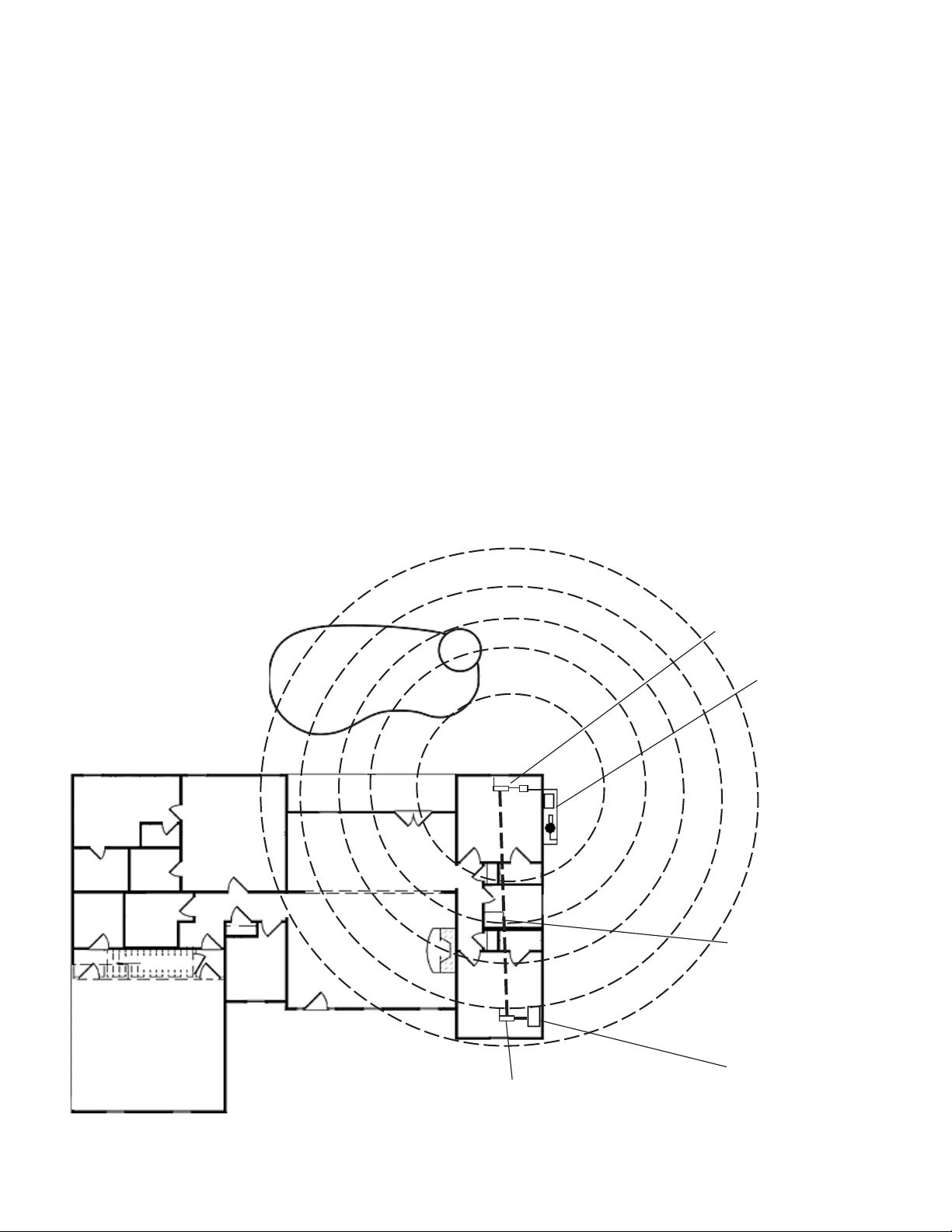
Recommended Wireless Router and Protocol adapter Location
Note: A first floor installation location is recommended to maximize the wireless signal strength. However, if
an upstairs installation is the only option, for the best reception it is recommended that the ScreenLogic
wireless router be located on the floor directly above where the Tablet or PDA will be primarily used.
Advantages:
• Good wireless coverage to back of home and pool/spa area
• Minimal Protocol adapter cable wiring
Disadvantage:
• Requires Ethernet cable connection to existing wired or wireless router connected to DSL or Cable modem.
Note: Only required if you plan to access the Internet. Use of the ScreenLogic interface does not require an
Internet connection.
• Requires Serial cable run from Protocol adapter to Load Center
ScreenLogic Protocol
Note: For wireless Tablet and
PDA interfaces: If the Ethernet
cable pull as shown is not
possible or practical, you can
use the Range Extender Kit
(P/N 520561) which will
transfer the wireless signal to
the room in your home where
the wireless Tablet and/or PDA
are primarily used. For more
information, refer to page 20
and 86.
Pool
Weak
Spa
Medium
Very
strong
Adapter and Wireless
Router (wireless router
requires an AC wall
outlet)
Equipment Pad/
Load Center
FAMILY ROOM
IntelliTouch ScreenLogic User’s Guide
KITCHEN
LIVING ROOM
WAN
STUDY
Port 1-4
Existing wired or
wireless router
Ethernet (CAT5) cable
connects ScreenLogic
wireless router WAN
port to existing wired or
wireless router port 1-4
Existing
DSL/Cable
Modem
Page 29
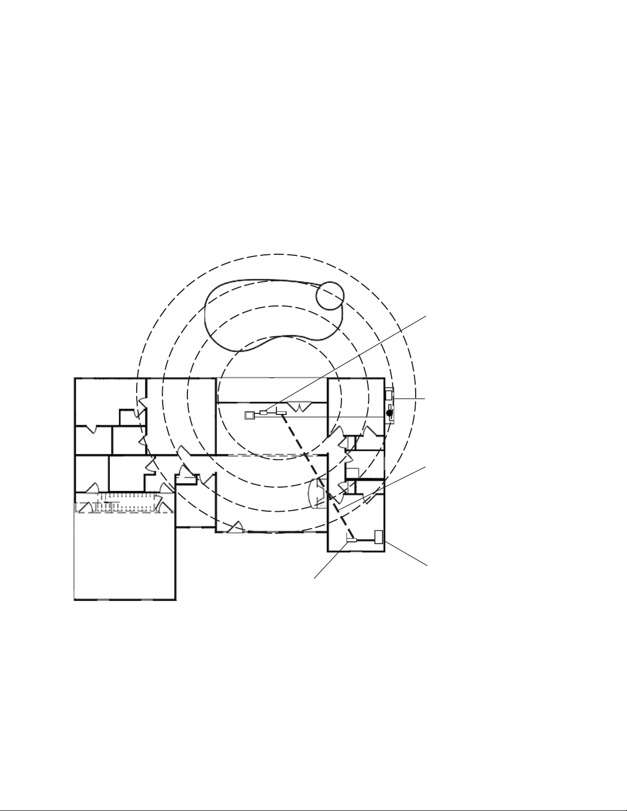
Wireless router and Protocol adapter with existing Indoor Control Panel (option)
In some cases the homeowner will already have an existing IntelliTouch Indoor Control Panel. The fourwire conductor cable used to connect to the ScreenLogic Protocol adapter can tap in the Indoor Control
Panel’s four-wire connector or cable.
Advantage:
• Can tap into existing IntelliTouch Indoor Control Panel connector or cable
• Minimal Protocol adapter serial cable wiring
• Good wireless coverage to back of home and pool/spa area
Disadvantage:
• Requires Ethernet cable connection to existing wired or wireless router connected to DSL or Cable
modem. This is only required if you plan to access the Internet. Use of the ScreenLogic interface does
not require an Internet connection. See note at bottom of page.
19
Weak
FAMILY ROOM
Medium
Pool
Very
strong
KITCHEN
LIVING ROOM
Spa
Existing wired or
wireless router
Protocol ScreenLogic
Adapter taps into
existing IntelliTouch
Indoor Control Panel and
connects to the wireless
router via Ethernet cable
Equipment Pad/Load
Center
Ethernet (CAT5) cable
connects ScreenLogic
wireless router WAN port to
existing wired or wireless
router port 1-4
STUDY
Existing DSL or Cable
modem
Note: For wireless Tablet and PDA interfaces: If the above Ethernet cable pull is not
possible or practical, you can use the Range Extender Kit (P/N 520561) which will
transfer the wireless signal to the room in your home where the wireless Tablet and/or
PDA are primarily used. For more information, refer to page 20 and 86.
IntelliTouch ScreenLogic User’s Guide
Page 30
20
Adding Range Extender Kit for Large Home and Properties
For larger homes and properties it may be necessary to install the wireless Range Extender kit (P/N 520561). The
wireless Range Extender kit transfers the wireless signal for better coverage where you primarily use your Tablet
and/or PDA. The wireless Range Extender kit consists of two wall-plugs that plug into your home’s AC power wall
outlets. The first wireless extender wall-plug connects to the ScreenLogic wireless router via an Ethernet cable
(RJ45/CAT5). The second wall-plug does not require connection wires. This wireless extender wall-plug picks up
and broadcasts the ScreenLogic wireless router signal for better coverage in the area of the home where the
wireless Tablet and/or PDA are primarily used. For more information about the Range Extender, see page 86.
Advantages:
• Better wireless coverage for larger homes and properties
• Good wireless coverage to back of home and pool/spa area
• Use your home’s electrical wiring instead of running an Ethernet cable
Disadvantage:
• Requires Serial cable run from Protocol adapter to Load Center
Second wireless
range extender
wall-plug
FAMILY ROOM
Pool
LIVING ROOM
wireless router, and
first wireless range
extender wall-plug
(via Ethernet cable)
KITCHEN
ScreenLogic
Spa
IntelliTouch
Protocol Adapter
connected to Load
Center (*)
STUDY
Existing DSL
or Cable
modem
Existing wired
or wireless
router
Note (*) A wireless connection is available from the Protocol Adapter to the Load Center. This
eliminates the existing hard wire connection from inside your home to the equipment pad. For more
information see “ScreenLogic Wireless Connection Kit” on page 97.
IntelliTouch ScreenLogic User’s Guide
Page 31

Connecting without Broadband Internet Access
This connection setup is for homeowner’s that do not have a Broadband Internet connection.
Note: Use of the PDA, Tablet, or in-wall touch screen does not require the use of a PC.
To connect the IntelliTouch ScreenLogic hardware:
1. Connect the Protocol adapter to the wireless router: Connect an Ethernet cable (CAT 5) to the Ethernet
RJ45 jack located on the Protocol adapter. Connect the other end of the Ethernet cable to LAN Port 1 on
the back panel of the wireless router. The LED indicator for LAN Port 1 will be on to indicate proper
connection. Ensure that a straight-through CAT 5 cable is used to connect to wireless router. A crossover
Ethernet cable will not work.
2. Connect to the PC: Insert a separate Ethernet cable (CAT 5) to the LAN Port 2 on the back panel of the
wireless router, and to an available Ethernet port on the network adapter in the computer. Use a straightthrough CAT 5 cable to connect to the wireless router. The LAN Port 2 LED indicator will be lit to indicate
proper connection.
3. Connect to the Protocol adapter: Proceed to “Connect to the Protocol Adapter,” page 24.
21
Ethernet cable
(RJ45 - CAT 5)
IntelliTouch
ScreenLogic
Wireless router
1
234
Existing PC
(not required)
WAN
Wireless PDA
In-wall Touch Screen
Protocol Adapter
Indoor Control Panel *
Four-wire
(22 gauge)
(Connects to
the Personality
board)
Load Center
(Located outside at
equipment pad)
Wireless Digital Tablet
Note: (*) Optional wiring for existing Indoor Control Panel. Tap into the Indoor Control Panel
connector or pig tail off the four-wire cable connected to the Personality board.
Cable Distant Limits:
• Ethernet cable distance limit = 300 feet
• Four-wire cable distance limit = 1500 feet
IntelliTouch ScreenLogic User’s Guide
Page 32

22
Connecting to your Home Network with Broadband Access
While not a requirement to run ScreenLogic, IntelliTouch ScreenLogic can coexist with and utilize your existing
home network’s Broadband connection. There must be either an Ethernet-based Cable or DSL modem with an
established Broadband Internet account from an Internet Service Provider (ISP).
By connecting IntelliTouch ScreenLogic to your existing home network you will be able to take advantage of
weather forecast information and current weather conditions in your area. In addition, you can utilize the other
Internet enabled applications that exist on the PDA, Tablet, and in-wall Touch Screen such as Web browsing, e-mail
and much more.
Connecting to an existing home network
To connect to an existing home network:
1. Connect the Protocol adapter to the wireless router: Connect an Ethernet cable (CAT 5) to the Ethernet
RJ45 jack located on the adapter. Connect the other end of the Ethernet cable to PORT 1 of the four
Ethernet LAN ports located on the back of the wireless router. Use a straight-through CAT 5 cable to
connect to wireless router. A crossover cable will not work.
2. Connect to the existing home network router: Connect an Ethernet cable (CAT 5) to the WAN Port on
the back of the ScreenLogic wireless router. Connect the other end of the Ethernet cable to a LAN Port on
the existing home network router. The existing home network router can be wired or wireless. Use a straightthrough CAT 5 cable to connect to wireless router. A crossover cable will not work.
Note: The existing home wired or wireless router needs to be set to Dynamically Assign IP (DHCP
enabled) addressing in order to assign a Subnet to the IntelliTouch wireless router to operate with the
IntelliTouch ScreenLogic system.
Note: For users with Broadband Internet connections, Pentair always recommends that the
homeowner have an existing wired or wireless router connected to their DSL or Cable modem. The
ScreenLogic wireless router should always be setup to piggy-back off this existing router and never
should be setup to be the only router directly plugged into the DSL or Cable modem.
3. Connect in-wall touch screen to the IntelliTouch wireless router: If you have an in-wall touch screen
(iTC35 Kit P/N 520502), connect an Ethernet cable (CAT 5) from the bottom RJ45 jack of the in-wall to the
LAN Port on the back of the IntelliTouch wireless router.
4. Connect to the Protocol adapter: Proceed to “Connect to the Protocol Adapter,” page 24.
Installing the Range Extender Wall-Plugs for Large Homes/Properties
For larger homes and properties, you may need to use the wireless Range Extender kit (P/N 520561) to transfer
the wireless signal to the room near where the wireless Tablet and/or PDA will be primarily used. The following
diagram illustrates the wireless Range Extender connection.
To install the wireless Range Extender wall-plugs:
1. Connect the Ethernet cable (RJ45/CAT5) from the Ethernet Bridge Range Extender wall-plug to a LAN port
on the ScreenLogic wireless router.
2. Plug the Ethernet Bridge Range Extender wall-plug into an AC power wall outlet near the wireless router.
3. Plug the other Range Extender wall-plug into an AC power wall outlet located in a room where the wireless
Tablet and/or the PDA will primarily be used. When all three LEDs on the Range Extender are lit, the
installation is complete.
IntelliTouch ScreenLogic User’s Guide
Page 33

Connecting to your Home Network with Broadband Access (Continued)
23
RJ11 for DSL
Coax for Cable
INTERNET
RJ11
DSL or
Cable Modem
Ethernet cable
(RJ45 - CAT 5)
RJ45
(RJ45)
Existing wireless router
(mandatory)
1
234
WAN
ScreenLogic
Wireless router
- LAN 1
234
WAN
Range Extender (Ethernet
Bridge) wall-plug (Plugs into
AC power wall outlet - Connect
to LAN Port via Ethernet cable)
In-wall Touch
Screen
Ethernet cable
(RJ45 - CAT 5)
Protocol
Adapter
Wireless Extender wall-plug
(Plugs in to AC power wall
outlet Located in a room
where the Tablet and/or PDA
will be primarily used)
Four-wire
(22 gauge)
(Connects to
the Personality
board)
Load Center
(Located outside at
equipment pad)
Existing PC
Wireless PDA
Wireless Digital Tablet
Note: (*) Optional wiring for existing Indoor Control Panel. Tap into the Indoor Control Panel
connector or pig tail off the four-wire cable connected to the Personality board.
Cable Distant Limits:
• Ethernet cable distance limit = 300 feet
• Four-wire cable distance limit = 1500 feet
Indoor Control
Panel (*)
IntelliTouch ScreenLogic User’s Guide
Page 34

24
Connect to the Protocol Adapter
The IntelliTouch ScreenLogic Protocol adapter is connected to the Personality board located in the Load Center or
Power Center via a four-wire cable. Before connecting the cable to the adapter, first determine the length of cable
required for the connection.
Protocol Adapter Location: The IntelliTouch wireless router and Protocol adapter should be located inside in a
dry environment, preferably near the home owners DSL/Cable modem. If the wireless router is too far from the
pool area, then you may need to move the wireless router closer to the pool area by running an Ethernet cable from
the DSL/Cable Modem connection out to the Protocol adapter and wireless router. For wireless router location
requirement, refer to “ScreenLogic Location Requirements,” page 17.
Note: Existing Indoor Control Panel - If there is an existing IntelliTouch Indoor Control Panel, you can
tap directly into the wire in the home or pig tail off the connector in the Indoor Control Panel. This avoids
having to run a separate four wire from the Load Center to the Protocol adapter.
To connect to the Protocol adapter:
1. Connect the Four-Wire Cable: Run a four conductor cable (22 AWG UL approved) from the Load
Center or Power Center location to the adapter. Place the adapter in a dry area near the wireless router.
Ideally, both devices should be located near the home owners DSL or Cable modem.
2. Grasp the Protocol adapter with one hand, and with your other hand gently pull outward on screw terminal
connector to remove it from its socket.
3. Strip back the four cable conductors ¼ inch. Insert the four wires into the connector screw terminals. Secure
the wires with the four screws. Make sure to match the color coding of the wires with the pin colors indicated
on the adapter label. The pin numbers and wire color codes are:
1 BLK = Ground
2 GRN = -DT
3 YEL = +DT
4 RED = +15 VDC
4. Insert the screw terminal connector onto the pins on the adapter circuit board. Note that the connector is
keyed for the correct orientation.
5. Proceed to “Connect to the Personality Board,” page 25.
Screw terminal
connector
BLK = Ground (1)
GRN = -DT(2)
YEL = +DT(3)
RED = + 15 VDC (4)
Pull connector
out to remove
Protocol Adapter
IntelliTouch ScreenLogic User’s Guide
Ethernet (RJ45)
connector for
connection to
wireless router
Page 35

Connecting to the Personality Board
WARNING
enclosure high voltage cover-panel. It is required that the main power into the home be switched
OFF at the main circuit breaker box whenever the high voltage cover-panel is removed. The main
power must also be switched OFF to access the Power/Load Center enclosure low voltage
raceway.
The following steps describe how to connect the four conductor cable to the Personality board.
1. Switch the main power OFF to the Load Center.
2. Unlatch the front door spring latches, and open the front door of the Load Center.
3. Remove the screws securing the high voltage cover-panel. Remove the cover-panel from the enclosure.
4. Loosen the two upper access screws from the Outdoor Control Panel.
5. Lower the Outdoor Control Panel down to access the Personality board.
6. Route the four conductor cable (22 AWG) cable in through a knockout at the bottom of the low voltage
raceway, then route the cable up through the low voltage raceway to an available COM port on the
Personality board.
-
Read the following WARNING information before removing the Power/Load Center
25
Access screw
(Outdoor Control
Panel)
Cover-panel
screw
Low-voltage
raceway
Load Center
Access screw
(Outdoor
Control Panel)
Cover-panel screw
(Cover-panel not
shown)
IntelliTouch ScreenLogic User’s Guide
Page 36

26
7. Strip back the cable conductors ¼ in. Insert the four wires into the screw terminals on either COM PORTS
(J7 or J8) plug located on the left side of the Personality board. Secure the wires with the four screws. Make
sure to match the color coding of the wires: The pin numbers and wire color codes are:
1 BLK = Ground
2 GRN = -DT
3 YEL = +DT
4 RED = +15 VDC
Note: Multiple wires may be inserted into a single screw terminal.
CAUTION Do NOT short GND or +15 VDC connections (Red or Black) to data lines (Green or Yellow).
The Personality board may be permanently damaged. Do NOT reverse GND or +15V or system will not operate.
8. Install the cover-panel and secure with the two retaining screws.
9. Close the hinged Outdoor Control Panel and secure with the two access screws.
10. Close the front door of the Load Center. Fasten the spring latches.
BLK
GRN
YEL
RED
Personality board
(Connector J7 or J8)
IntelliTouch ScreenLogic User’s Guide
Page 37

Start up the IntelliTouch ScreenLogic System for the first time
After the ScreenLogic Protocol adapter and wireless router are installed, power up the system and verify that all
cables are properly connected.
To start up the system
1. Power up the Load Center and Protocol adapter: Switch the main power on to the Load Center. The
Protocol adapter will also be switched on and its RED power LED should be lit. The Protocol adapter
receives power from the Personality board COM port located in the Load Center.
2. Connect power to the IntelliTouch wireless router: Connect the AC power adapter to the receptor on
the back panel of the wireless router and then plug the other end of the AC power adapter to a wall outlet or
power strip. The Power LED will be on.
• Check that the appropriate LEDs are lit on the front of the wireless router. The LED light for active LAN and
WAN Port will illuminate to indicate proper connection. Note: The WAN port will only be lit if connected to
the homeowner’s wireless/wired router.
3. Switch on the Tablet, PDA or PC/Laptop: After the device is powered up you need to start the IntelliTouch
ScreenLogic application to configure ScreenLogic for the type of IntelliTouch system being used.
27
4. Configure ScreenLogic for installed IntelliTouch equipment: Proceed to “Accessing IntelliTouch
ScreenLogic Configuration Program,” page 30.
IntelliTouch ScreenLogic User’s Guide
Page 38

28
Blank Page
IntelliTouch ScreenLogic User’s Guide
Page 39

Configuring ScreenLogic
29
IntelliTouch ScreenLogic User’s Guide
Page 40

30
Accessing IntelliTouch ScreenLogic Configuration Program
This section describes the Configurator utility dialogs used to configure ScreenLogic. Follow the Configurator utility
dialogs, Steps 1 through 5 to configure ScreenLogic for the installed IntelliTouch equipment. The Configurator utility
should display upon powering up your Tablet, or in-wall Touch Screen. If using a PC/Laptop, you must first run the
setup program on the IntelliTouch ScreenLogic installation CD-ROM, then click on the ScreenLogic icon on the
Desktop to launch the Configurator utility.
Note: Do not run the Configurator utility while using ScreenLogic. Before starting the Configurator Utility,
you must first exit from the ScreenLogic interface.
Installing IntelliTouch ScreenLogic Software on a PC or Laptop (iTC15 Kit only)
To install the IntelliTouch ScreenLogic software on a PC or Laptop:
1. Insert the ScreenLogic CD into your CD-ROM drive, the Setup Wizard should automatically display. If it
does not display, click ScreenLogic.exe on the CD-ROM to start the Setup Wizard.
2. Press Next and follow the on-screen instructions. The ScreenLogic icon will be installed on your desktop.
Start the Configurator Utility on the Tablet or In-Wall Touch Screen
To start the Configurator utility on the wireless Tablet or in-wall Touch Screen:
• Power up the device. If the Configurator utility is not running, double-tap the IntelliTouch ScreenLogic icon on
the desktop. The Configurator utility main screen will display.
• To access the Configurator utility while running ScreenLogic: Press the virtual keyboard button (see page 11)
to display the virtual keyboard. Tap the Ctrl key, then the Q key to close ScreenLogic, then double-tap the
IntelliTouch ScreenLogic icon on the desktop.
IntelliTouch ScreenLogic User’s Guide
Page 41

Start ScreenLogic Program
To start ScreenLogic after using the Configurator utility:
1. After completing Steps 1 through 5 of the Configurator utility, click the Finish button. The Configurator utility
main screen will display.
2. Click the Start ScreenLogic button.
To start ScreenLogic from the Desktop:
1. Double-click the IntelliTouch ScreenLogic icon on your Desktop.
2. Click the Start ScreenLogic button.
Start the Configurator Utility on the PDA
To start the Configurator utility on the PDA:
• Power up the device. From the desktop, tap Start > IntelliTouch
ScreenLogic. The Configurator utility main screen will display.
31
• To access the Configurator utility while running ScreenLogic: Tap the X tab
to exit ScreenLogic (as shown on right), then from the desktop, tap Start >
IntelliTouch ScreenLogic.
Note: If you cannot locate the ScreenLogic program, you will need to install
it. For installation instruction see “Setting up the PDA for the first time” on
page 87.
PDA Main Screen
Exit ScreenLogic Program
To exit ScreenLogic on the Tablet:
1. Press the Virtual Keyboard button (first left-side button on the front of the Tablet case).
2. Tap the Ctrl and q key to exit ScreenLogic.
3. Tap OK to close the keyboard.
Transfer Time from the Configurator Utility
Note: Changes and commands made in the Configurator utility may in some cases not be immediate.
Depending on how many changes are made it could take up to 30 seconds to transfer the new settings to
the IntelliTouch system. Using the Schedule feature could take longer.
Compatibility with IntelliTouch Systems
ScreenLogic is compatible with all versions of IntelliTouch systems. In some cases, the ScreenLogic interface may
be used with an IntelliTouch system that has an older version of firmware. Some of the ScreenLogic features will
not operate unless the IntelliTouch firmware is up to date. Example features that may not work include support for
12 lights, Dimmer module support, and 3rd party chlorinator support. Contact your pool builder or Pentair to
purchase the latest IntelliTouch Personality board if these features are necessary.
IntelliTouch ScreenLogic User’s Guide
Page 42

32
ScreenLogic Configuration and Maintenance Screen
The Configurator utility opening screen displays the type of IntelliTouch system equipment, firmware and software
versions being used. From this screen you can start the Configurator utility to configure ScreenLogic for the
IntelliTouch system, or start the ScreenLogic program.
• To start the Configurator utility: Tap the Configure
IntelliTouch button, read the warning message and tap
Continue. Proceed to configure ScreenLogic using the
dialogs (Steps 1 through 5). After you are done, click the
Finish button to return to the opening screen.
• To start ScreenLogic: Tap the Start ScreenLogic button.
The Main screen is displayed.
General Settings (Step 1 of 5)
Use the following Time Zone table to
determine your location.
enoZemiT.S.U)TMG(emiTnaeMhciwneerG
emiTnaiiawaH)00:01-TMG(
emiTnaksalA)00:90-TMG(
danaC
&SU(emiTcificaP
anaujiT;)a
emiTniatnuoM)00:70-TMG(
emiTlartneC)00:60-TMG(
emiTnretsaE)00:50-TMG(
)00:80-TMG(
IntelliTouch ScreenLogic User’s Guide
Page 43

General Settings (Step 1 of 5) Continued
emaNnoitpircseD
kcolC metsysllastesytiliturotarugifnoCehtnitesemit&etadehT
:etaD .raeydnahtnom,yadtnerruceht
teS
:ruoH .setuniMdna)MP/MA(ruohtnerrucehtteS
noitacoL
:enoZemiT .noitacolruoyrofenozemitehtteS
:edocPIZ lli
oitidnoc
33
tllaW-nI,ADPehtrofskcolc
tarugifnoCehtnitesetad
etad&emiT:etoN.ytilituro
.noitcennoctenretnIdnabdaorBaseriuqererutaef
hcuoTilletnI,telbaT,neercshcuo
&emitCPehtfI.lenaPlortnoCroodnIdna,lenaPlortnoCroodtuO
cigoLneercSehtnodeyalpsidetad&emitehthctamtonodetad
&emitehtotetad&emitCPehtteserotdeenuoy,neercsemoH
.setunimwefaekatyamsmetsysllarofnoitazinorhcnys
wnoitamrofniedocpiZ.S.U.noitacolruoyrofedocPIZ
dnasetanidroocedutitgnoLdnaedutitaLehtetalupopyllacitamotua
dnatsacerofrehtaewehtyalpsidsgnittesesehT.enoZemiT
sihT.aeraruoyrofnoitamrofniesirnusdna,tesnus,sn
elacSerutarepmeT
srosneSetarbilaC
POlaunaM
egaPemoH
nottubkcaB.egapsuoiverpotoG
nottubtxeN )5fo2petS(egaptxeneh
ytiroirP
drowssaPsseccAetomeRteS "drowssaPsseccAetomeRteS"ehtsseccaotnottubsihtesU
sgnitteStrelAliamEsserddaliameehtretnE
nottubhsiniF .ytliturotarugifnoCehttixednasgnittestnerrucevaS
muSlooP riadnaaps,looptnerrucehtsyalpsiD
htaewtnerruc
oyssecca
totoG
:suisleC/tiehnerhaF niserutarepmet
:pU/nwoD-riA .erutarepmettnerrucesi
:pU/nwoD-looP .erutarepmettnerrucesiaR/rewoL
:pU/nwoD-apS .erutarepmettnerrucesiaR/rewoL
.emuserlliwmargorp
:yram
:ylnOrehtaeW ehtnosnoitidnocre
ssaptluafedehT.golaid
drowssapehT.drowssap
.suisleCrotiehnerhaFseerged
aR/rewoL
:ytiroirPnoitarepOlaunaM nrutlliwerutaefsiht,delbanenehW
.neercsniaMcigoLneercS
htaewtnerrucruoysyalpsiD
:yrammuSlooP+rehtaeW rehtaewtnerrucruoysyalpsiD
rowssapehtevasotKOkcilC.desu
h.wwwtisivoslA.yletomermetsys
.yletomermetsysru
lautcAdnatnioPteSyalpsiD
ehT.edirrevopmuplaunamwollaotmargorpdeludehcsynaffo
deludehcsehthcihwretfa,sruoh21siemittluafednoitcnuflaunam
delbanedna,sutatsedomtaeh,stnioptesdna,serutarepmet
y(snottubotdnopserroctaht)wolley(stiucricyrailixua
.noitacolruoyrofsnoitidnocre
.egapemoHehtnonoitamrofnimetsysdnasnoitidnoc
htobnidrowssapon(knalbsidrow
ehthctamtsumgolaidsihtnidesu
dna"drowssaPweN"ehtmorfsksiretsaehtesare,drowssap
otriatnep/moc.cigolemo
ehtno)wolle
yalpsidottenretnIehtotdetcennocebtsumuoY.egapemoH
deretneehtfoecalpniraeppalliwsksiretsA.sexobdrowssap
ruoytegrofuoyfI.yletomermetsysruoysseccaotdesudrowssap
eblliw)knalb(drowssaptluafedehT.sexob"drowssaPmrifnoC
otyletomergnitcennoC"eeS.d
ruoygnisseccatuobanoitamrofnirof89egapno"metsysruoy
otuoyselbanehcihwytilitu"tcennoCcigoLneercS"ehtdaolnwod
IntelliTouch ScreenLogic User’s Guide
Page 44

34
Changing the Display to Show Fahrenheit to Celsius
Temperature set point and actual temperature settings are displayed on the Main screen in either Fahrenheit or
Celsius.
To change the temperature scale:
1. Start the ScreenLogic Configurator utility, and tap Configure IntelliTouch.
2. On the General Setting page under Temperature Scale, tap either Fahrenheit or Celsius.
3. Tap Finish when done to save the setting.
Calibrating Temperature Sensors
The IntelliTouch system includes two temperature sensors (10 kohm) for water and ambient air temperature. The
IntelliTouch i10+3D model for dual bodies of water has three sensors. You can add an additional sensor for
controlling solar heating systems.
Generally, these sensors are accurate and you do not have to calibrate them. However, long plumbing runs and
water features can cause temperatures at a body of water to be different from the temperature sensor reading. You
can manually recalibrate the sensors to adjust for this.
Before you start, you need an accurate all weather thermometer. If you are calibrating the air sensor, wait until the
sensor is not in direct sunlight.
There is a Water Temp and Air Temp setting. If you have an i10+3D system, you will see Spa Temp, Pool Temp,
and Air Temp. Calibrate the Spa and Pool temperatures the same way as described below for Water Temp. For
the i5, i5S, i7+3, or i9+3 system, there is a water and air temperature sensor. Make sure to locate the air
temperature sensor in the shade for accurate readings.
To calibrate the air, pool and spa sensors:
1. First, tap the Pool or Spa button on the ScreenLogic Main screen to switch on the spa or pool filter pump.
2. Tap Configure IntelliTouch to start the ScreenLogic Configurator.
3. Place the thermometer in the spa or pool. Take an accurate temperature reading. When calibrating the air
sensor, place the thermometer next to the air sensor. The sensor is normally located near or under the Load
Center or Power Center enclosure, not inside the enclosure. Take an accurate temperature reading in the
shade.
4. On the General Setting page under Calibrate Sensors, use the Up or Down arrows to raise or lower the Air,
Pool and Spa temperature to match the corresponding thermometer temperature reading. If you have an
i10+3D repeat the above for the pool. The i10+3D has three sensors, one each for the spa and pool water
and one for the air temperature.
5. Press Finish when done.
IntelliTouch ScreenLogic User’s Guide
Page 45

emaNnoitpircseD
stiucriCputeS .metsysehtrofstiucricelbaliavaehtsyalpsiD
:retneCdaoL .)s(retneCnoisnapxEror
etneCdaoLdellatsniehtsyalpsiD
:tiucriC syalpsiD.)01-1(stiucricerutaeFdnastiucricXUAelbaliavaeht
XUAforebm
uneht,metsyshcuoTilletnIehtfoledomehtnognidnepeD
.draobytilanosrePehtnodetacolerastiucricXUA.yravyamst
iucric
:emaNtiucriC .emantiucricdengissA
:noitcnuFtiucriC .noitcnuftiucricdengissA
:ezeerF/wnO .noitcetorpe
zeerfhtiwdengissatiucriC
sgnitteStiucriC rofserutaefgnithgilriatnePdna,snoitcnuf,emantiucricelbaliavaeh
tsyalpsiD
.tsilniamehtnideyalpsidstiucricdetceles
:emaNtiucriC fotsiletelpmocrof04egapees(tiucricfoemaN
.
semandenifedresu02sedulcnioslA.)semanstiucrichcuoTilletnI
:noitcnuFtiucriC .)tsilrof93egapees(noitcnuft
iucricfoemaN
ezeerFhtiwnO looPasahcus,tiucricynanohctiwsotnoitposihttceleS:
wolebsporderutarepmetriaehtf
itiucricapSdnaF°63,tiucriclooParoF.
pmupretlifeht,tiucricapSaroF.noitcetorpezeerfevahlliwpmupretlifeht
51
taapsdnaloopneewtebhctiwslliwsevlavaps/loopehtdnanurlliw
renaelCretsaMehtroF.noitidnocezeerfehttuohguo
rhtslavretnisetunim
retaweviecerspmuprenaelclooP.dedeentonsinoitcetorpezeerf,tiucric
.pmupretlifehtmorf
wolf
:noitisoPLAS/mAS .thgilLAS/mASapsroloopfonoitisoP
nottubsemaNmotsuCteS .sliatedrof24egapeeS.tiucricaotemanmotsucangissA
nottubsthgiLlaicepS tnesednacnirehtodna,leehWroloC,sthgilrolocLAS,mASngissA
.sliated
rof63egapeeS.egapsthgiLehtniyalpsidotsthgilderoloc
yalpsiDcigoLneercS:htiwwohS :looP no"looP"rednutiucric
cificepsarofnottubaecalP
.neercsniaMeht :apS "apS"rednutiucriccificepsarofnottubaecalP
.neercsniaMehtno :s
erutaeFretaW rednutiucricarofnottubaecalP
tiucricsthgiLaesoohcuoyfI.neercsniaMehtno"serutaeFretaW"
ehtno
deyalpsidsyawlasinottubthgileht,thgillaS/maSronoitcnuf
.neercssthgiL
nottubkcaB.egapsuoiverpotoG
nottubtx
eN)5fo3petS(egaptxenehtotoG
nottubhsiniF .ytliturotarugifnoCehttixednasgnittestnerrucevaS
Setup Circuits (Step 2 of 5)
35
IntelliTouch ScreenLogic User’s Guide
Page 46

36
Setup Circuits (Step 2 of 5) Continued
Special Lights Button
Use this button to display the “Special Lights” dialog. Lights displayed
in this dialog are circuits that are assigned as “Lights.” All Lights
assigned in this dialog will be controlled by the All Off, All On, Color
Set, Color Sync, and Color Swim buttons on the Lights screen. Up to
12 SAm, SAL, lights and the Color Wheel can be configured to use
the Color Set, Color Sync, and Color Swim lighting features.
Feature Circuit Configuration Button
The Feature Circuit Configuration button is enabled after you select
a Feature Circuit (1 - 10) from the main list of circuits, assign a circuit
name and circuit function. Use this button to access the “Configure”
dialog. The selected Feature Circuit will be the name of the macro (i.e.
Fountain). To access the Feature Circuits, scroll down to the end of
the available AUX circuits, select the name of the Feature Circuit.
There are 10 available Feature Circuit names that can be assigned
multiple functions in the Configure Macro dialog. You can also assign a
custom name to the circuit (see page 42).
emaNnoitpircseD
tiucriC .tiucricorcamasadesuebnactahtstiucricelbaliavaehtsyalpsiD
.stiucricfotsil
erongIffO/nO orcaMahctiwsoT.tiucricorcaMdetcelesaetavitcaotnOtceleS
nottubenoD.golaidesolcdnagnittesevaS
ehtmorfdetcelessitiucriCerutaeFanehwdelbanesinottubsihT
.orcaMdetcelesehtesutonot,erongItceleS.ffOtceles,ffo
IntelliTouch ScreenLogic User’s Guide
Page 47

Feature Macro Circuits Overview
Feature Macro Circuits can control equipment that is not controlled by AUX circuits. In general, AUX circuits are
used for high voltage equipment like pumps and lights, whereas Feature Macro Circuits are used for low voltage
equipment like valve actuators. However, Feature Macro Circuits can go beyond this definition, and be used in
other creative ways. For example, a Feature Macro Circuit can be used to create a Macro circuit in which several
other circuits can be switched on or off with the same button. There is a limit of 10 Feature Macro circuits in the
system. Feature Macros are not available with i5 or i5S systems.
• Valve Actuators - Feature Macro Circuits may be assigned for controlling up to five valve actuators per
Load Center. To control a total of five actuators requires the installation of the optional Valve Module (P/N
520285) which includes three additional actuators outputs (C, D, and E) per Load Center. For more
information about configuring valve actuators, refer to page 45.
Note: When using solar heat, note that for shared equipment pool and spa combination, valve A is
always used for solar. For dual body dual equipment, valve A is always the pool and valve B is always
the spa.
• Two-Speed Pump - A Feature Circuit may be assigned as a way to switch a two-speed Filter Pump from
high speed to low speed.
37
• Spa Spillway - A Feature Circuit may be assigned to activate the Spa Spillway effect, where in a pool/spa
combination, pool water is diverted to the spa then spilled back into the pool.
Note: For details on setting up Feature Circuits, see “Creating a Feature Circuit Macro,” page 41.
Freeze Protection
Freeze protection switches on a circuit if the outdoor air temperature sensor detects the temperature is getting close
to freezing (below 36° F). The system cycles through all circuits that have been assigned freeze protection, and runs
the circuits for 15 minutes to stop the pipes from freezing. This is especially important if there is a pool and spa
combination. If freeze protection is set to both the spa and pool circuits, the filter pump switches on and the pool
and spa valves alternate every 15 minutes to keep the water moving in both the pool and spa. This process
continues until the freeze condition is over.
IntelliTouch ScreenLogic User’s Guide
Page 48

38
Assign a Circuit Name and Function
Note: Before you assign circuit names in ScreenLogic, write down the circuit names and assigned buttons
on the Outdoor Control Panel (in the Load Center). The circuit names you assign in ScreenLogic should
match the button labels on the Outdoor Control Panel.
Circuit Functions let you assign special logic to the circuits. For example, when setting up an automatic pool cleaner
pump, you would assign the circuit function MASTER CLEANER. With this “Cleaner” logic the cleaner pump
would not run without the filter pump being on first, and, the cleaner pump would automatically shut off whenever
the spa is switched on. The cleaner will go on after the five minute delay. Also, the automatic cleaner pump will turn
off when the spa and/or solar is turned on. Be careful not to duplicate circuit names with these circuits. These
circuits may also be used to activate two-speed pumps to high speed, turn additional valves, etc.
To assign a circuit name:
1. Start the ScreenLogic Configurator and click Configure IntelliTouch.
2. Click Next on the General Setting page. The Setup Circuits (Step 2 of 5) page is displayed.
3. From the Circuit Name drop box, scroll through the alphabetical list of predefined circuit names and select a
circuit name. For a complete list of the IntelliTouch Circuit Functions, see page 39.
Note: You can also customize circuit names. To enter a custom circuit name, click Set Custom Names,
and select one of the user names (USER NAME 01-20) and type in the new circuit name (11 characters
maximum). The Custom Names (USER NAME 01-20) can be found at the bottom of the circuit name
drop down box. If you are using the Tablet, use the virtual keyboard to enter the new name. For more
information about the virtual keyboard button, see page 11.
4. From the Circuit Function drop-down box select the function assigned to the circuit name. For a complete
list of the IntelliTouch circuit functions, see page 39.
Note: If the assigned function requires freeze protection, select the check box for “On with Freeze.”
Note: When you are finished setting the first circuit name and circuit function, repeat Steps 3 and 4 and
assign the other circuits and functions. Depending on the IntelliTouch model you are programming,
equipment may not be installed for all available circuits shown.
5. Display Circuit Button on ScreenLogic main screen: For easy access, the assigned circuit button can be
displayed under Pool, Spa, or Water Functions on the ScreenLogic Main screen. To display the button on the
Main screen, select where you want the button to display in the Show with drop-down box.
Note: IntelliBrite, SAm, SAL lights, and Color Wheel buttons will always display on the Lights screen.
6. Click Finish to save the current settings.
IntelliTouch ScreenLogic User’s Guide
Page 49

IntelliTouch Circuit Functions
The following Circuit Functions allow you to assign special logic to the circuits.
Note: To ensure proper operation, some circuits shown below will only display on certain screens.
For example, SAm and SAL Lights will always display on the Lights screen, not on the Main screen.
39
cireneG
.seitilibapacelbammargorp
ren
aelcretsaM
:gniwollof
hterofebsetunim5nopmupretlifehtsecroF-
.nosiapsehtnehwfforenaelcehtsnruT-
unim5roffforenaelcehtsnruT-
thgiL
remmiD
thgiLMAS
esunehw)46egap
l
thgiLLAS
)26egaphtiwdesunehwLA
rotareneGnotohP
ePsteL
.serutaefgnithgi
gnithgilroloclaicepssetavitcA ees(neercssthgilsroloCerugifnoCehtnoserutaef
S.sthgilapsehtnidengissaebtsumthgilLASehT
iLlaicepS
.serutaefgnithgil
oC,nOllA,ffOllAehtesuotgolaidsthgiLlaicepS
.serutaefgnithgil
.stratsrenaelce
CerugifnoCehtnoserutaefgnithgilroloclaicepssetavitcA
ehtllahtiwtiucricafolortnocffO/nOelpmiS.cigollaicepsonhtiwtiucricA
ehtseodtI.rotautcaevlavrenaelcrospmuprenaelcloopcitamotuahtiwskroW
.snigebgnitaehralosehtnehwset
.nollAdnaffOllAsthgilsahcus,krowotserutaefgnithgillaicepsswollA
.)604025N/P(dellatsniebtsumyalergnimmiD.krowotserutaefgnimmidthgilswollA
ees(neercssthgilsrolo
ehtnidengissaebtsumthgilMASehT.sthgilloopMAShtiwd
miwSroloCdna,cnySroloC,teSroloC,nOllA,ffOllAehtesuotgolaidsthgiLlaicepS
miwSroloCdna,cnySroloC,teSroloC,nOllA,ffOllAehtesuotgolaidsthg
miwSroloCroteSroloCybdetarepoebblubcitporebifskrowrebiFriatn
ehtnidengissaebtsumthgilsihT.gnithgilLASdnaMAShtiwdesunehwsmargorp
miwSroloCdna,cnySroloC,teSrol
leehWroloC
)26egap.skrowrebiFriatnePhtiwdesunehw dengissaebtsumthgilleeh
S
yawllipS
renaelCroolF
etirBilletnI
.serutaefgnithgilmiw
.nodenrutsierutaef
gnithgilroloclaicepssetavitcA ees
WroloCehT
morfretawehtslluppmupretlifehttahtosevlavnrutereht
fretawagnitaerc,apseht
yaw-3asevomgnittessihT
.sdaehpu-popehtdeeftahtsevlavmetsys
.thgilDELetirBilletnInasetavitcA
IntelliTouch ScreenLogic User’s Guide
(nneercssthgilsroloCerugifnoCehtnoserutaef
roloCdna,cnySroloC,teSroloC,nOllA,ffOllAehtesuotgolaidsthgiLlaicepSehtni
sevomgnittessihT.loopehtevobadesiarsiapsehterehwsnoitanibmocaps/looproF
ottisnruterdnaloopeht
sihtnehwffodenruterasrenaelcloopcitamotuA.tceffella
renaelc2neewtebwolfgnitanretlasetunim02yreveevlav
Page 50

40
IntelliTouch Circuit Names
AERATOR
AIR BLOWER
AUX 1
AUX 2
AUX 3
AUX 4
AUX 5
AUX 6
AUX 7
AUX 8
AUX 9
AUX 10
BACKWASH
BACK LIGHT
BBQ LIGHT
BEACH LIGHT
BENCH
BLOWER
BOOSTER PUMP
BUG LIGHT
CABANA LTS
CHEM. FEEDER
CHLORINATOR
CLEANER
COLOR WHEEL
DECK LIGHT
DRAIN LINE
DRIVE LIGHT
EDGE PUMP
ENTRY LIGHT
FAN
FIBER OPTIC
FIBERWORKS
FILL LINE
FLOOR CLNR
FOGGER
FOUNTAIN
FOUNTAIN 1
FOUNTAIN 2
FOUNTAIN 3
FOUNTAINS
FRONT LIGHT
GARDEN LTS
GAZEBO LTS
HIGH SPEED
HIGH TEMP
HOUSE LIGHT
JETS
LIGHTS
LOW SPEED
LOW TEMP
MALIBU LTS
MIST
MOTOR VALVE
MUSIC
(NOT USED)
OZONATOR
PATH LIGHTS
POOL SAM 3
SECURITY LT
SLIDE
SOLAR
SPA
SPA HIGH
SPA LIGHT
SPA LOW
SPA SAL
SPA SAM
SPA WTRFLL
SPILLWAY
SPRINKLERS
STREAM
STATUE LT
SWIM JETS
WTR FEATURE
WTR FEAT LT
WATERFALL
WATERFALL 1
WATERFALL 2
WATERFALL 3
WHIRLPOOL
WTRFL LGHT
YARD LIGHT
USER NAME 01 ____________________
USER NAME 02 ____________________
USER NAME 03 ____________________
USER NAME 04 ____________________
USER NAME 05 ____________________
USER NAME 06 ____________________
USER NAME 07 ____________________
USER NAME 08 ____________________
USER NAME 09 ____________________
USER NAME 10 ____________________
USER NAME 11 ____________________
USER NAME 12 ____________________
USER NAME 13 ____________________
USER NAME 14 ____________________
USER NAME 15 ____________________
USER NAME 16 ____________________
USER NAME 17 ____________________
USER NAME 18 ____________________
USER NAME 19 ____________________
USER NAME 20 ____________________
Note: Custom Circuit names can be up to 11
characters.
IntelliTouch ScreenLogic User’s Guide
Page 51

Creating a Feature Circuit Macro
Feature Macros give you the ability to combine various circuits together so a single button can operate them all at
once. For example, you could create a Macro that would give you one button that turns on your spa, spa light,
fountain, fountain light, and patio lights. A Macro also has the capability to switch a circuit off. You can assign a
name to your Macro from the list of IntelliTouch circuit names. For the complete list of names, see “IntelliTouch
Circuit Names,” page 40. You can also create your own custom name, for example, SPA PARTY could be used if
there was a spa fountain which should not be on when spa is on (because it could put cold water in the spa) it can
be set up in the Macro to automatically switch off when SPA PARTY is switched on. An OFF Macro can also be
used to switch any number of lights off with one button.
Before you create a Feature Macro circuit, first assign a feature circuit name and function, (see page 38).
Note: A Feature circuit may not be set as Dimmers although they can turn on light dimming circuits.
To create a Macro circuit:
1. Start the ScreenLogic Configurator and tap Configure IntelliTouch.
2. Tap Next on the General Setting page. The Setup Circuits (Step 2 of 5) page is displayed.
41
3. From the main list of assigned circuits, scroll the list down after the AUX circuits until the Feature circuits are
displayed.
4. Tap the Feature Circuit configuration button. The selected macro dialog box is displayed.
5. From the list of circuits, select the circuit that will control a valve:
• To switch a circuit ON, tap On.
• To switch a circuit OFF, tap Off.
• To set a circuit to be unaffected by the macro, tap Ignore.
Note: Be careful when you select circuits to switch on. One macro can switch on another macro circuit,
resulting in systems switching on or off that you do not want on or off.
6. Tap Done to close and save the macro setting and close the dialog.
7. Under ScreenLogic Display, in the Show with box, select where you want the Macro button to appear. For
more information about displaying buttons on the main screen, refer to “Setup circuits (Step 2 of 5),” page 35,
and “Display a Circuit Function Button on the Main Screen,” page 42.
8. Tap Finish when done.
IntelliTouch ScreenLogic User’s Guide
Page 52

42
Creating Custom Names for Auxiliary Circuits
There are nearly 100 circuit names stored in the IntelliTouch software (see page 40). If you cannot find one to fit
your application you can create up to 20 custom names.
To create a custom circuit name:
1. Start the ScreenLogic Configurator and tap Configure IntelliTouch.
2. Tap Next on the General Setting page. The Setup Circuits (Step 2 of 5) page is displayed.
3. Select an AUX circuit from the main list.
4. Tap the Set Custom Names button. The Custom Names dialog is displayed.
5. Tap USERNAME-01 from the list. Enter the new circuit name in the box. The new name can be a maximum
of 11 characters. The Custom Names (USER NAME 01-20) can be found at the bottom of the circuit name
drop down box. If you are using the Tablet, use the virtual keyboard to enter the new name. For more
information about the virtual keyboard button, see page 11.
6. Tap Set Name to save the custom name. The new name is displayed in the Custom Names list.
7. Tap Done to save and close the dialog.
8. The custom name is displayed in the main Circuit Names lists and now can be used when assigning a new
circuit.
Display a Circuit Function Button on the Main Screen
An assigned circuit function can be displayed as a button on a ScreenLogic main screen. For more information
about displaying circuit buttons on the main screen, refer to “Setup circuits (Step 2 of 5),” page 35.
To display an assigned circuit button:
1. Start the ScreenLogic Configurator and tap Configure IntelliTouch.
2. Tap Next on the General Setting page. The Setup Circuits (Step 2 of 5) page is displayed.
3. In the list of assigned circuits, select the circuit you want to change.
4. Under ScreenLogic Display, in the Show with box, select where you want the button to appear, under Pool,
Spa or Water Features on the ScreenLogic Main screen. For example, if the AUX 2 circuit is assigned to a
Cleaner, selecting Pool from the “Display with” box will display a Cleaner button under the Pool button on the
ScreenLogic Main screen. Up to 20 buttons can be displayed under Water Features on the ScreenLogic
Main screen. Use the right arrow button to scroll through other assigned buttons.
5. Tap Finish when done to save the setting.
IntelliTouch Indoor Control Panel Circuit Names
Custom circuit names used in the Configurator utility need to be updated in the IntelliTouch Indoor Control Panel in
order for these names to display in the Indoor Control Panel.
To update the Indoor Control Panel to display the current circuit names:
1. Press Menu > Setup > Advanced > Circuit Names.
2. Select the new circuit name, then press the Exit button. The display will show the same circuit names as
shown in ScreenLogic.
IntelliTouch ScreenLogic User’s Guide
Page 53

Configure Other Equipment (Step 3 of 5)
43
emaNnoitpircseD
stnemngissAevlaV smetsyshcuoTilletnIllA.sevlavotdengissastiucricehtsyalpsiD
noitpOevlaV
rotanirolhC
taeHlaunaM
.eviffolatotarof)Edna
:retneCdaoL .retneCdaoLniamehtnielbaliavasevlaV
:evlaV yamAevlaV.BdnaAstiucricevl
.noitautca
lhC tinunoitanirolhcasierehtfixobsihtkcehC:
.87egap
tneserProtaniro
:taeHlaunaMapS apsnigebyllacitamotuaotnoitposihttceleS
avretneCdaoLelbaliavA
.apsehtsyawlasiBevlavdna
sA
:evlaVotdengissAstiucriC .evlavaottiucricangis
:noitcaevlavgnirudffopmuP evlaverofebffopmupehthctiwS
tsiapsehtrevenehwgnitaeh
of)BdnaA(srotautcaevlavyrailixuaowtlortnocnac
sgnisunehW:etoN.detcelessixob
.delbanenoitposihthtiwtaehtonlliwaps
snoitacilppar
ehtfonoitiddaehthtiW.serutaefretawdnagnitaehralossahcus
eht,retneCdaoLehtnidellatsni)582025N/P(eludoMevlaV
,D,C(srotautcalanoitiddaeerhtotpuetadommoccalliwmetsys
kcehc"tneserpraloS"ehtnehwtiucricrehtoynahtiwdesuebton
derahsroftahteton,taehralo
rofdesusyawlasiAevlav,noitanibmocapsdnalooptnempiuqe
loopehtsyawlasiAevlav,tnempiuqelaudydoblaudroF.ralos
ees,tinurotanirolhcehtgnitarepotuobanoitamrofnieromroF.dellatsni
tluafedehT.yllaunamnodenru
eht,retlifotdemmargorpsiapsruoyfI.)dekcehcxob(nosignittes
IntelliTouch ScreenLogic User’s Guide
Page 54

44
Configure Other Equipment (Step 3 of 5) - Continued
emaNnoitpircseD
tnempiuqEraloS-apS/looP laudfI.tnempiuqederahssetacidnisnoitpotnempiuqeapS/looP
:tneserPraloS sinoitposihtnehW.elbaliavasignitaehraloS
,detceles raloSybdesU:AevlaV evlaVehtnideyalpsidsi,
.tnempiuqe
oapSdnalooP,desugniebsitnempiuqeydob
.tnempiuqefostesnworiehthtiwhcae,deyalpsid
erasnoitp
ralosrofdesugniebsiAevlavtahtgnitacidni,tsilstnemengissA
syaleD
nottubkcaB.egapsuoiverpotoG
nottubtxeN.)5fo4petS(egaptxenehtotoG
nottubhsiniF .ytliturotarugifnoCehttixednasgnittestnerrucevaS
udnopmuP uoyfixobkcehcsihttceleS
pmuPdeepShgiHgnideeNstiucriC otdeentahtstiucricerutaeFdnastiucriCehtsyal
psidtsilsihT
ehtesU addAtiucriC ro tiucriCevomeR evomerroddaotnottub
:pmuPtaeHasiraloS slortnocpmuptaehsesuerutaefsihT
.metsysgnitaehralosafoecalpnidesu
:nwod-loocretaehgnir
uqeehtretfasetunimnetrofnoyats
.pmupdeepsowtaseriuqertahttiucrica
uptaehafixobkcehcsihttceleS.raloSfodaetsni
.ffoseogtnempi
.nodehctiwsnehwedomdeepshgihnipmupehtevah
gniebsipm
foynafI.pmupdeepshgihaotstiucricelpitlumngissanacuoY
.ffodehctiwsnehwedomdeepswolsnidna,edomdeepshgih
Configuring Valve Actuators (Controlled by AUX or Feature Circuit)
All IntelliTouch systems can drive two auxiliary valve actuators (A and B) for applications such as solar heating and
water features. With the addition of the Valve Module (P/N 520285), installed in the Load Center, the system can
accommodate up to three additional actuators (C, D, and E) for a total of five. Before configuring auxiliary valve
actuators, first assign names to the AUX or FEATURE circuits (page 35). Auxiliary valve actuators can be
controlled by any AUX circuit or Feature circuit. Please note that the i5 and i5S models do not include FEATURE
circuits and therefore must use the AUX circuits for controlling valve actuators. By using FEATURE circuits to
control valve actuators, you can conserve your AUX circuits for high voltage relays for controlling pumps and lights.
You can also use Macro circuits to couple valve actuators with AUX circuits for specific applications.
pmupretlifehttahtseriuqertahttnempiuqerehtororetaehaevah
.edomdeepshgihotpmupehthctiwslliwti,noerastiucriceseht
niebdluohspmupeht,nosehctiwsniatnuofanehw,elpmaxeroF
Use the following information to calculate the number of available valves:
• Main Load Center or Power Center (all models) = 2 (A & B)
• Valve Module (if yes enter 3) = 3 (C, D & E)
• Number of Expansion Centers (3 x 2) = 6 (A & B)
• Number of Valve Modules on Expansion Center (13x 3) = 3 (C, D & E)
TOTAL = 20
IntelliTouch ScreenLogic User’s Guide
Page 55

Configuring Valve Actuators
To assign a valve actuator:
1. Start the ScreenLogic Configurator and tap Configure IntelliTouch.
2. Tap Next on the General Setting page and on the Setup Circuits page. The Configure Other Equipment
(Step 3 of 5) page is displayed.
3. Select the Load Center or Expansion Center(s) and the AUX valve actuator (A, B) you wish to configure
from the Valve Assignments list.
Note: When using solar heat, note that for shared equipment pool and spa combination, valve A is
always used for solar. For dual body dual equipment, valve A is always the pool and valve B is
always the spa.
Valve A: Can be used for solar heating or auxiliary valve actuator control. If the “Solar present” check box is
selected “USED BY SOLAR” is displayed in the Valve assignment list. Valve A is automatically configured as
a solar heating valve actuator.
Valve B: Can be configured to be controlled by any circuit. Resides on the Personality board.
45
Valves C D E: Reside on the optional Valve Module board (P/N 520285) that is plugged into the Personality
board.
4. In the Circuit Assigned to Valve box, select the circuit that you would like to use to control the valve
actuator.
5. Repeat steps 3 and 4 for each valve actuator.
6. Tap Finish when done.
IntelliTouch ScreenLogic User’s Guide
Page 56

46
Setting up Additional Equipment
The following describes how to set up any special equipment that may be attached. Your system may or may not
have this equipment installed.
The following information describes:
• Setting up a two-speed pump - Setup circuits that switch the filter pump from low to high speed.
• Setup Solar equipment - Enable solar or heat pump.
• Cool-down cycle for the heater - Set a cool-down cycle for heaters that require it.
• Enable “Spa Manual Heat” control - Heats the spa using the Spa button on the ScreenLogic Main screen
or the spa-side control, even when the heater is set to OFF in the Heat screen. This lets the homeowner heat
the spa on-demand. Timed programs will not heat the spa.
Setting up a Two-Speed Pump
Equipment circuits displayed on this screen will automatically switch a two-speed filter pump to high speed when
these circuits are switched on. For example you can have the Filter pump switch to high speed whenever the JETS
or CLEANER is on.
To assign a two-speed pump to a circuit:
1. Start the ScreenLogic Configurator and tap Configure IntelliTouch.
2. Tap Next on the General Setting page and on the Setup Circuits page. The Configure Other Equipment
(Step 3 of 5) page is displayed.
3. Scroll through the previously assigned circuit names to add
another circuit for switching filter pump to high speed. Select a
circuit to assign to a high speed pump from the Add a circuit
box. Continue to add another circuit. You can use a Feature
Circuit as one of the circuits which can switch the pump to high
speed (except for models i5 and i5S).
Note: With a dual equipment system i10+3D, one circuit
button is assigned to control the spa pump and the pool
pump. For more details, refer to “Configure Other
Equipment (Step 3 of 5),” page 43.
4. Repeat step 3 for each circuit requiring a two speed pump.
5. Tap Finish when done.
IntelliTouch ScreenLogic User’s Guide
Page 57

Setup Solar Equipment and Heat pump option
Solar equipment is configured in the “Configure Other Equipment (Step 3 of 5)” dialog, page 43.
To configure solar equipment:
1. Start the ScreenLogic Configurator and tap Configure IntelliTouch.
2. Tap Next on the General Setting page and on the Setup Circuits page. The Configure Other Equipment
(Step 3 of 5) page is displayed. For i10+3D Dual Equipment, tap the Solar present check box for each
body of water with solar heating.
3. Tap the Solar present check box to enable solar heating. Valve A: USED BY SOLAR is displayed indicating
that valve A is assigned for solar operations.
• If your heat pump is being used instead of solar panels, tap the Solar is a heat pump check box,
then assign a circuit to the valve in the “Circuit Assigned to Valve” box.
Note: If solar heat source is enabled (Solar present check box selected) then the Valve A
actuator will be dedicated to the solar valve actuator. Setting the system to Heat pump (Solar is
a heat pump) will free Valve A for use on other valves.
47
4. Tap Finish when done.
Set a Cool-Down Cycle for the Heater
To activate the pump during a heater cool-down:
1. Start the ScreenLogic Configurator and tap Configure IntelliTouch.
2. Tap Next on the General Setting page and on the Setup Circuits page. The Configure Other Equipment
(Step 3 of 5) page is displayed.
3. Tap the Pump on during heater cool-down check box under the “Delays” option.
4. Tap Finish when done.
Note: Pentair heaters do not require this feature.
IntelliTouch ScreenLogic User’s Guide
Page 58

48
Enable Manual Spa Heat Control
If this option is selected, your spa will begin to heat whenever it is manually turned on, (by pressing the Spa button
on the ScreenLogic main screen), even if the heater is set to OFF. Your spa will also begin to heat when turned on
by the spa-side remote, or QT4 wireless remote. This feature allows you to program your spa to filter daily with the
heater set to off, and then be ready to heat whenever the SPA button is pressed manually on the ScreenLogic Main
screen. This feature is switched on by default.
To set manual heat control for the spa:
1. Start the ScreenLogic Configurator and tap Configure IntelliTouch.
2. Tap Next on the General Setting page and on the Setup Circuits page. The Configure Other Equipment
(Step 3 of 5) page is displayed.
3. Tap the Spa Manual Heat check box.
4. Tap Finish when done.
Chlorine Generator
The IntelliTouch system is designed to operate with the following salt chlorine generators:
• AutoPilot Pool Pilot Digital
• GoldLine Aqua Rite
• Clear Tech Automation AutoClear Plus
Note: Call your manufacturer for compatibility with IntelliTouch systems.
Activate the Chlorinator Control Interface
Before operating the chlorinator control interface you must first activate the system to control the chlorinator from
the ScreenLogic. ScreenLogic can control the chlorinator but does not turn the chlorination system on or off. When
the chlorinator control is disabled in ScreenLogic, the chlorinator is still operating but must be controlled at the
chlorinator control panel.
To obtain chlorination status and make adjustments:
1. Start the ScreenLogic Configurator and tap Configure IntelliTouch.
2. Tap Next on the General Setting page and on the Setup Circuits page. The Configure Other Equipment
(Step 3 of 5) page is displayed.
3. Tap the Chlorinator present check box to enable chlorination.
4. Tap Finish.
Note: For information about Chlorinator user controls, refer to “Equipment Tab,” page 76.
IntelliTouch ScreenLogic User’s Guide
Page 59

Configure IntelliFlo (Step 4 of 5)
IntelliTouch can support up to eight IntelliFlo and four IntelliFlo 4 pumps in any combination with up to eight
pumps. For more information refer to the IntelliFlo Installation and User’s Guide (P/N 350075). IntelliFlo pumps
can be connected to IntelliTouch as follows:
• 8 IntelliFlo
• 7 IntelliFlo + 1 IntelliFlo 4
• 5 IntelliFlo + 3 IntelliFlo 4
• 4 IntelliFlo + 4 IntelliFlo 4
49
IntelliFlo Pump 1
emaNnoitpircseD
)sbaT8-2pmuP(1pmuP pmupolFilletnIehthctamtsumpmupehttatessserddaehT
epyT olFilletnIroolFilletnI;desugniebsipmupfoepythcihwtceleS
nuorgkcaB deludehcsedulcnihcihw”,sretemaraPretliF“ehtotdeitsitiucricsihT
wolF/tiucriC
kcaB.egapsuoiverpehtotoG
txeN.egaptxenehtotoG
hsiniF .ytliturotarugifnoCehttixednasgnittestnerru
tiucriCd
criC .pmupehtetarepoottiucricehttceleS
uqE
gniretliFdnuorgkcaB looproF.snoitpogniretlifloopehtsseccaotnottubsihtsserP
.061x4
:wolF .tiucricdengissaehtot)MPG031-51(etarwolfehttceleS
cevaS
IntelliFlo 4x160 pump 2
rcssihtnodetceles)8-1sbat(rebmun
httasserddapmupehttesotdeentonod
ro,7#,6#,5#,4#,3#,2#,1#ottes
.8,#
revonrutdna,semitnurdemmargorp
:tiu
ogniretlif
.05egapees,snoitp
tiucriC.pmupe
.)"gniretliFdnuorgkcaB"ees(gniretlifloopelbaneottiucric
letnInagnisunehwsyalpsidylno)MPG(etarwolfehT
tluafedehtsi1pmuP.nee
uoy,dellatsnipmupenoylnosierehtfI.pmuptsrifehtrofsserdda
)ylnoolFilletnI(gniretlifdnuorgkcabdnaetarwolf,stnemngissa
elpitlumeraerehtfI".1pmuP"otylppagolaidsihtnoputes
.spmupehtputesotsbat8-2pmuPehtesu,spmupolFilletnI
cigoLneercS/hcuoTilletnIhtiwspmupolFilletnIelpitlumgnisunehW
ebnacsserddaehT.pmuphcaeotsserddanangissaotdeenuoy
"loop"ehtottiucricsihtngissA.s
.pmupolFil
ehT.deyalpsidsi"MPR"ylno,pmup061x4olFilletnInagnisunehW
ehtmorfnodenrutsitiucricsihtnehW.deyalpsidtonsietarwolf
dengissaehttaetarepolliwpmupeht,neercspmuptnempi
smargorpretlifdeludehcsynaedirrevoyletaidemmilliwdnaMPG
.)"gniretliFdnuorgkcaB"ees(gniretlifloopetarepootputes
IntelliTouch ScreenLogic User’s Guide
Page 60

50
Configure IntelliFlo (Step 4 of 5) - Continued
Filtering dialog
Pool filtering schedules (start/stop times) are only used for filtering. The pump only allows four such events to exist.
These schedules for the circuit (pool) are then transferred to the pump, and used to calculate the energy saving /
minimum speed function of the IntelliFlo for the basic filter mode. See page 50 for details. IntelliFlo will calculate the
required flow rate based on your pool size, clean filter pressure, pool turns per day and cycles per day, and will
control the motor speed to keep a constant flow. IntelliFlo is constantly monitoring the filter when it detects that the
system is dirty, an alert message is displayed. For more information about alert messages for IntelliFlo and IntelliFlo
4x160 pump, see “Equipment IntelliFlo Screen” on page 79. You must then clean the filter by performing a
Backwash cycle (see page 52).
emaNnoitpircseD
sretemaraPretliF .gniretlifrofdesuylnoera)semitpots/trats(seludehcsgniretliflooP
.edomretlifcisabehtrofolFilletnI
eziS fos’0001sadesser
srevO-nruT
ctsom
retliFlaunaM
-
srevonrut8-1 sitI.yadrepsnrutthgieotpuotputesnacuoY
MPG03tluafeD(031-51 ehthcihwtawolfehtstesretli
FlaunaM-)
rpehtgnirudedom'retliF'ehtni
pxesieulav”emulovloop“ro"ezis"loopehT
.noitamrofnilanoitiddarofnoitadnemmocer
sesehT.tsixeotstnevehcusruofswollaylnopmupehT
dna,swolf,setarnrutniatsusoteulavsihtsesu
orpromargorpsihT.yadyreveMP00:4otMA00:8
.semit
seludehc
otdesudna,pmupehtotderefsnartnehtera)loop(tiucricehtrof
ehtfonoitcnufdeepsmuminim/gnivasygreneehtetaluclac
ehT.ezisloopehtroflagK0001ot1morfretnE.)lagK(snollag
etaruccaeromehthguohtla,etamitseesolcaebnacrebmunezis
edomretliF.edomretlifninehwenodeblliwsnrutehtrettebeht
rofnoitavresnocygrenerofyadrepnrutenotesotdednemmocer
rezitinasruoyotrefer,oslA.slooplaitnedisernommo
nurylnolliwpmupolFilletnIehT.yllaunamnodenrutsitifinurlliwpmup
ehtfi,elpmaxeroF.semitdemmargo
morfnurottiucricloopehtrof)semitpots/trats(demmargorpsipmup
ybdesuerasmarg
otsemit’NO‘esohtnevignurtsumtideepstahwtaetaluclacotolFilletnI
.edomretlifcisabehtrofloopdezistahtrof)s(revonrutehteveihca
IntelliTouch ScreenLogic User’s Guide
Page 61

Configure IntelliFlo (Step 4 of 5) - Continued
Filtering dialog (Continued)
emaNnoitpircseD
sretemaraPmuucaV ehtetarepooT.yllaunamloopehtnaelcotedommuucaVehtesU
.re
temarap
wolF )MPG05tluafeD(MPG031-51morfsietarwolfmuucaV
emiT
tesgnittessihT
.muucav
sretemaraPgnimirP htiwepipnoitcusdnapmupehtgnillifsnaempmupa”emirp“oT
uoy
ploopeht
”wolFgnimirP“
tsysloopelohweht
mirPxaM
wolFe
iwretemarap
rptonlliwpmup
tessiretemarap
sa
emiTemirPxaM
lFilletnItnawuoytaht
eb
)sruoh01(setunim006-1 retemarapsihT-)setunim
)MPG55tluafeD(MPG031-51 sihtstratspmupehtemityrevE-
).nim51tluafeD(.niM51-1 emitehttesotretemarapsihtesU-
01tluafeD(-
.etelpmocsignimirpnehw”demirP“
.ytefasdnasgnivastsocrofelbissop
tnIehT.elcycsihthguorhtseogdna
.tnereffideblliwsmetsyslla,revewoh
51
cuoTilletnIehtecalp,edommuucaVnipmup
letnIehtnonottubmuucaVehtsserpnehtnacnosrep
pehtdnaderaelcebdluowretemaraptrelaegakcolbeht
nacuoytahttpecxe”2dna1erutaeF“olFilletnIotlacitnedi
ytefaS.nottubmuucaVehtgnisuedomsihttratsyllaunam
wolfmuucaVehtgnittesnehwedamebdluohssnoitaredisnoc
loopehtnurothsiwuoyemitfotnuomaehts
cusehtllamorfriaehtsetaucavessecorpsihT.retaw
upaemirpotreisaesitI.htgneldnaezisepip,retawfohtped
ehT.ecnerefersawolfahtiwdetratssirotomehtemityreve
syalpsidtnemomarofnehtdna”gnimirP“syalpsidDCLlenap
yamdnatnednepedmetsyssi”wolf“sihT.emi
sihtnahteromwolfrevenlliwpmupehT.noitaretieriuqer
irpateglliwuoyrekciuqehtemitehtrewol
iartsehtfI.sdnoces03nahtsselniemirpdluohsdevomer
lenaplortnocroodtuoh
ecivresloopehT.pmupolFilletnIehtpotsdna”,edoMecivreS“ni
.pmupolFil
neht,sretemarapmuucaVteserpehttaetarepodluowpmupehT
lliwpmu
gnitarepO.edomlortnocwolfnisetarepoylnoedommuucaV.pots
s
iedomsihT.srosnesspmupehtfollaffostuhsedommuucaVni
.setunim01signitteslacipytehT.setunim006ot1morftesebnac
dnasenilnoit
ehtnognidnepedemirpotsetunimlarevesekatyamtI.pmupeht
fipm
retawehT.sepipdnapmupehtmorfepacseotriaehtllawolla
,emirpdlohtonodspmuP.epacsenacriaehtsselnuretnetonnac
desunoitcnufasignimirP.ksattahtsahmetsysgnipi
.pmupehtfonoitareporeporpehtserusnenoitcnuf
fonoitareporeporpserusnenoitcnuf”emiTgnimirPmetsyS“ehT
lortnoceht,gnimirpsipmupehtnehW.me
wolfehtfI.pmupehtfowolfmumixamehtetaitogenll
ehtwolotsiwolfehtfI.rucconacegamadtnempiuqe,hgihootsi
pupmarotpmupehtrofnommocsiti,revewoh,ot
wolsawolfsihtpeekotyrtsyawlA.gnimirpelihwylkciuqnwoddna
.rorrenastropertierofebemirpdnayrto
stratstiemityreveemirpniattalliwolFilletnIehttahtrebmemeR
naclaeslacinahcemolFille
ehT.sruccoegamadereveserofebsetunim51tuobadnatshtiw
metsysehtfirorregnim
reniartsehtgnivahtuohtiwloopdebmulpllewA.emirpottluciffidsi
sahren
ehtnisiriafotnuomalaitnatsbusadnagninaelcrofdevomerne
,egarevaehtnosdnoces09ot06tuobaniemirpdluohstimetsys
IntelliTouch ScreenLogic User’s Guide
Page 62

52
Configure IntelliFlo (Step 4 of 5) - Continued
Filtering dialog (Continued)
emaNnoitpircseD
emiTxaMmetsyS trohsaniemirplliwpmupegarevaehT-).nim0tluafeD(.nim5-0
veilerni
elborpemoceb
ibaehtsahpmupehtesuacebemitfodoirep
vorpnacwolfgnimirptahtswolfhgiheriuqer
setunim5otpu,emitfotnuomadenimretederpamargorp
.elcycputratshcaetaelcycgnimirp
otflestirotinomotytil
tahtsmetsysrofsi”emiTxaMmetsyS“.demirpsitierusekam
demeedsititubedi
nacredliubehT.riaehtllaeveileryllufotdedeensiemiteromtaht
diaot,
.gnibmulplacitrevxelpmocrosretliftluciffidmorfriaehtgni
spartriaegralerehwdesuebylnodluohs”emiTxaMmetsyS“ehT
ehtmrofnilliwyalpsidehT.metsysehtnihtiwsm
ehtgniruddehsinifsitinehwdnadegagnesisihtnehwresu
PhsawkcaB ISP01(erusserplaitnereffidretlifehttahtstcetedpmupehtnehW
wolFhsawkcaB
emiTesniR
nottu
benoD.sgnittesevasdnagolaidesolC
sretemara
erusserPretliFnaelC
emiThsawkcaB
deen
031-51 )ISP06tluafeD(
desaercnisah)ecnereffid
htecuderot)dehsawkcab(denaelcebtsum
fehthsawkcaboT.sliatedrof97egapeeS.retlifehtfo
sawkcabehttratsot
sielcychsawkcabehtretfA.)MPGwolfteserpdnaemitelcyc
yc”esniR“eht,dehsinif
ehtfirodetelpmocneebevahselcycesehtretfA.detucexe
tdesserpsinottubpotS/tratS
.niagadetareposiedomh
grahcerauoyfI.levelerusserpdaehorezstiteserolFilletnIeht
ehtegrahc,metsys
tlifnaelc%ehtteserotnoitisopretlifeht
.edomretlif
-)ISP41sitluafeD(ISP05-1 neewtebsignittesISPegarevaehT
ysehtnierehwynamorfemoc
enoospuemocotegassemtrelaeht
ISP
setunim06-1 )setunim5tluafeD(
setunim06-1 )etunim1tluafeD(
,erusserp”retliFnaelC“ehttawonsidna
retlifehttahtsetacidnitahtegassemtrelanasyalpsidhcuoTilletnI
retliF"A.erusserpe
sutatstnerrucehtsetacidnineercs"tnempiuqE"ehtnorab"sutatS
uoy,retli
sserp,edom”ecivreS“nihcuoTilletnIecalp,olFilletnIpotsot
nottubhsawkcaBehtsserpneht,olFilletnInonottubpotS/tratSeht
teserpehtnurlliwolFilletnI.ssecorpwolfh
eblliwemitnoitarudteserpehthtiwelc
sutatsretlifeht,ssecorpehtpotso
retliFnehwderusaemerusserp-orezehtdnadetaluclacereblliw
sawkcabehtsretlifegdirtracgnisunehW
splehsihT.sretlifgnicalperrogninaelcnehwdemrofrepebtsumelcyc
EDagni
ehtretfA.elcycgninnurlamronagnirudtsrifmetsys
nievlavretlifehthtiwedomhsawkcabnipmupehtnur,degrahcsiretlif
nipmupehtnurnehT.sutatsre
nacsegnahcISPehT.sretlifdnaslooptsomrofISP02dnaISP01
sremmiksdeggolcelpmaxerof,mets
esuaclliwlevelrewolataretemarapsihtgnitteS.spmupnistopro
naelcotevahlliwuoydnar
.renoos)EDrodnas(retlifruoyhsawkcabro)egdirtrac(retlifruoy
IntelliTouch ScreenLogic User’s Guide
Page 63

Configure iS10 Spa-Side Remote (Step 5 of 5)
Note: For information about configuring switches on the iS10 Spa Side remote, refer to “Configure iS4,
iS10 and QT4 QuickTouch,” page 54.
emaNnoitpircseD
4#,3#,2#,1#01Si .setomeRediS-apS01SidellatsniehtrofstiucricngissA
)woRpoT(5,4,3,2,1nottuB
B mottobehtroftiucricelbaliavanatcelesotxobnwod-pordehtesU
nottubkcaB.egapsuoiverpotoG
nottubhsiniF .ytliturotarugifnoCehttixednasgnittestnerrucevaS
)woRmottoB(5,4,3,2,1nottu
.5dna,4,3,2,1snottub
.5dna,4,3,2,1snottubwor
53
worpotehtroftiucricelbaliavanatcelesotxobnwod-pordehtesU
emaNnoitpircseD
2#/1#4Si .etomeRediS-apS4SidellatsniehtrofstiucricngissA
4,3,2,1nottuB ,1snottubroftiucric
.4dna,3,2
nottubkcaB.egapsuoiverpotoG
nottubhsiniF .ytliturotarugifn
emaNnoitpircseD
)4TQ(hcuoTkciuQ .etomernoitcnufruof)4TQ(hcuotkciuQehtrofstiucricngissA
4,3,2,1nottuB ,1sno
.4dna,3,2
nottubkcaB.egapsuoiverpotoG
nottubhsiniF .yt
elbaliavanatcelesotxobnwod-pordehtesU
oCehttixednasgnittestnerrucevaS
ttubroftiucricelbaliavanatcelesotxobnwod-pordehtesU
liturotarugifnoCehttixednasgnittestnerrucevaS
IntelliTouch ScreenLogic User’s Guide
Page 64

54
Configure iS4, iS10, and QT4 QuickTouch
You can specify any iS4, iS10, or QT4 spa-side remote button to control different functions.
To configure the Spa-Side remotes:
1. Start the ScreenLogic Configurator utility and click Configure IntelliTouch.
2. Click Next on the General Setting, Setup Circuits and the Configure Other Equipment screen. The
Configure Spa-Side Remotes (Step 5 of 5) page is displayed.
3. Select the previously assigned circuit names that will control a valve.
• For iS10: Select iS10 #1 for the first iS10 spa-side remote access the setup dialog. The iS10 has ten
switches arranged in two rows of buttons. If there are multiple remotes, select iS10 #2, iS10 #3, or iS10 #4.
• For iS4: Select the iS4#1 (or #2 if there are multiple remotes) tab access the setup dialog. The iS4 has four
switches that can be configured.
• For QuickTouch (QT4): Select the Quick Touch tab to access the QuickTouch setup dialog. The QT4 has
four switches that can be configured.
4. Tap the down-arrow for each of the buttons you want to configure, then select the circuit from the list.
5. Press Finish when done.
IntelliTouch ScreenLogic User’s Guide
Page 65

Using ScreenLogic
55
IntelliTouch ScreenLogic User’s Guide
Page 66

56
Home Screen
The Home screen can be configured to display the current time, date and weather conditions for your location
as well as system information.
Tablet with Broadband Internet connection
emaNnoitpircseD
snoitidnoCtnerruC nacneercsemoHeht,derugifnocsicigoLneercSwohnognidnepeD
PDA with Broadband Internet connection
imetsysro,noitacolruoyrofsnoitidnocrehtaewyalpsid
cerasgnittes
.sliatedrof23egapeeS.ytilitu
.snoitidnocrehtaewyalpsidotnoitcennoc
tnerruC .tiehnerhafniseergedninwohserutarepmettnerruC
:dniW .ruohrepselimninwohsnoitceriddniwtnerruC
:tesnuS a
:pmeT
:llihCdniW .tiehnerhafniseergedninwohsrotcafllihcd
:ytidimuH .nwohsytidimuhtnerruC
:retemoraB .erusserpcirtemorabtnerruC
:tnioPweD .tniopwedtnerruC
:ytilibisiV .selimninwohsytilibisivtnerruC
:esirnuS tessino
rutciprehtaeW woldnahgihhtiwtsacrofrehtaewehtsyalpsiD
.serutarepmet
niwtnerruC
itacoL.noitacolruoyrofesirnusfoemittnerruC
.sgnittesedutitaLdnaedutignoLaiv.sliatedrof33egapeeS
.sgnittesedutitaLdnaedutignoL.sliatedrof33egapeeS
:se
esehT.noitamrofn
rotarugifnoCehtniegap"sgnitteSlareneG"ehtnoderugifno
snoitidnocrehtaewtnerrucehtfoyrammusasyalpsidneercsemoHehT
retnIdnabdaorBaotdetcennocebtsumcigoLneercS.noitacolruoyrof
ten
ivtessinoitacoL.noitacolruoyroftesnusfoemittnerruC
emiTdnaraeY,htnoM,yaDtnerrucehtsyalps
baTapS/looPehtsseccaotbatsihtpaT neercSniaM .
IntelliTouch ScreenLogic User’s Guide
iD.sliatedrof33egapeeS.emitdnaraey,htnom,yad
Page 67

Main Screen
The Pool/Spa Main screen displays the main control buttons for the pool, spa, and user defined water features.
57
Pool control button: Switches on Filter Pump and fires heater.
Shared equipment systems (i5, i7+3, i9+3); rotates valves to
pool position.
For shared equipment: When both Heat Mode buttons for the
pool and spa are set to on, if the Pool button is switched on, the
Spa button is off. The Heat Status display indicates that heat is
switched off to the spa while it is being used to heat the pool.
This button by default is always displayed on the Main tab.
To assign circuit buttons, see “Setup Circuits,” page 35.
Yellow/Grey button: A yellow
button indicates that the circuit
is switched On. A grey button
indicates that the circuit is
switched Off. Tap the button to
switch a circuit on, then tap it
again to switch it off.
Spa control buttons: For
shared (i5, i7+3, i9+3) and dual
(i10+3D) equipment systems;
switches on filter pump, rotate
valve actuator (to isolate spa
water from pool water), and fires
heater.
Pool/Spa heat controls: The Heat
Mode switches control the current
heat source being used.
Actual Temp displays the current
temperature of the pool/spa water
via the water temperature sensor.
Set Point displays the current
temperature that the heater is set to.
Water Feature buttons: These
buttons are user defined
circuits. To assign circuit
buttons, see “Setup Circuits,”
page 35.
Default Home Screen: After five
minutes, if there is no activity,
the Home screen will be
displayed.
Tabs:
Lights: Control your pool, spa, and landscape
lighting from this screen, see pages 60 and 61.
Schedule: Program pool, spa and lighting
schedules from this screen, see page 69.
History: View historical usage data for your pool,
spa, lights and solar, see page 75.
Equipment: Displays general system errors,
chlorinator controls, system delays and spa-side
enable/disable controls, see page 76.
IntelliTouch ScreenLogic User’s Guide
Page 68

58
Main Screen (Continued)
The Pool/Spa Main tab screen displays the main control for the pool, spa, and water features.
emaNnoitpircseD
serutaeFretaW/apS/looP ehtniderugifnocsadengissaresuerasnottubtiucricdeyalpsiD
icputeS“otrefer,neercsniameht
:snottubapS/looP loo
:snottubedoMtaeH ehT.ecruostaehehttcelesotsnott
ubesehtesU
:erasnoitceles
■ ffO .ecruostaehffohctiwS:
■ :retaeH .delbanesiretaehlooP
■ :derreferPpmuPtaeHroderreferPraloS taehralosesu,elbissopfI
.ecruos
■ :pmuPtaeHroraloS .ecruostaehehtsapmuptaeHroraloStceleS
:sutatStaeH setacidnioslA.desugniebecruostaehtner
rucehtsyalpsiD
.ffodehctiwssiecruostaehehtnehw
:nottubremraW esiaR.erutarepmetlooptniopteseht
C .erutarepmetlooptnioptesehtrewoL
:nottubreloo
cSgnirugifnoctuobanoitamrofnieromroF.ytiliturotarugifnoC
,cigoLneer
foynaotdengissaebnacsemantiucricdenifedresU.23egapotrefer
nosnottubgniyalpsidtuobanoitamrofnieromroF.snottubdeyalpsideht
dna53egap”,)5fo2petS(stiucr
24egap”,neercSniaMehtnonottuBnoitcnuFtiucriCayalpsiD“
pehtnohctiwsotsnottubapSdnalooPehtesU
derahsroF.)delbanesitaehlaunamapSfi(retaehdnapmupretlif
.noitisoploopehtotsevlavsetator;)3+9idna3+7i,5i(smetsystnempiuqe
IntelliTouch ScreenLogic User’s Guide
:pmeTlautcA .erutarepmetlooptnerrucehtsyalpsiD
:tnioPteS dnaremraWehtyb
tessatniopteserutarepmetlooptnerruC
.snottubrelooC
Page 69

Main Screen (Continued)
emaNnoitpircseD
serutaeFretaW thgimuoytahtstiucricfoselpmaxeerasnottubtiucricgniwollofehT
59
ednuyalpsid
”,neercSniaMeht
:nottubllafretaW asadengissaneebsahtiucricorcaMerutaeFsihT
tubniatnuoF nottubsihThdnapmupretlifloopehtnosehctiwS
:not
ehctiwselpmaxe
gniSroF
.tniop
.serutaeFretaWr
eromroF.rotarugifnoCehtnidenifederadeyalpsidsnottubgniwolofehT
osnottubgniyalpsidtuobanoitamrofni
24egap
ehctiwselpmaxenottubsihT.llafretaW
.tniopteSoterutarepmetloopehtstes;)S3+9i
totsevlavsetator;)3+9idna3+7i,5i(smetsystnempiuqe
puteS“otrefer,neercsniamehtn
nonottuBnoitcnuFtiucriCayalpsiD“dna53egap”,)5fo2petS(stiucric
retaehdnapmupretlifloopehtnos
3+7i,5i(smetsystnempiuqederahsroF.)delbanesitaehlaunamapSfi(
etsysydobelgnisrof.noitisoploopehtotsevlavsetator;3+9idna
loopehtstes;)S3+9i,S5i(smetsysydobelgniSroF.noitisoploop
derahsroF.)delbanesiretaehfi(retaeT.tniopteSoterutarepmet
,S5i(sm
.)delbanesiretaehfi(retaehdnapmupretlifloopehtnos
ehtotsevlavsetator;)3+9idna3+7i,5i(smetsystnempiuqederahsroF
.noitisoploopeh
teSoterutarepmetloopehtstes;)S3+9i,S5i(smetsysydobel
Configuring Pool and Spa Heating System Options
The IntelliTouch system allows for many different pool and spa heating options. In some instances, more than one
heating system may be installed. The system can then automatically select the heating system that is most effective
for your settings. However, before the system can take advantage of these options the system must be told what
kind of heating systems are installed.
To configure the heating system options for your pool or spa, use the Heat Mode button.
1. From the ScreenLogic main screen, in the for Pool or Spa, tap a Heat Mode button to select the type of
heat option to use. The Heat Mode choices are:
• OFF: No heating even though pump and other circuits may be operating.
• HEATER: Use the gas heater only.
• SOLAR PREF. or HEAT PUMP PREF. - Solar Preferred is used when solar and gas heating are available, and
you want to use solar heating only when it is most effective. Heat Pump Pref. is displayed if solar is set up as a
Heat pump (see page 43),
• SOLAR or HEAT PUMP: Solar is used when solar heating system is the only heat source.
2. To activate a heat source, tap the Heater or Solar button. To switch off the heater, tap the Off button.
3. Tap Finish when done.
IntelliTouch ScreenLogic User’s Guide
Page 70

60
Change the Pool and Spa Temperature
All pool and spa heat modes and temperature controls are located on the Main screen. The pool or spa will heat to
the settings specified on this screen.
Changing Pool Heat Settings
To raise the pool water temperature:
1. From the main screen choose Heater, Solar Preferred or Solar in the Heat Mode selection.
2. Tap the pool Warmer button. The pool will heat to the settings specified as indicated by the Set Point.
To lower the pool water temperature:
• Tap the Off button for Heat Mode or tap the Cooler button to change the new Set Point temperature.
Changing Spa Heat Settings
To raise the Spa water temperature:
1. From the main screen choose Heater, Solar Preferred or Solar in the Spa Heat Mode selection.
2. Tap the spa Warmer button. The pool will heat to the settings specified as indicated by the Set Point.
To lower the spa water temperature:
• Tap the Off button for Heat Mode or tap the Cooler button to change the new Set Point temperature.
Main Lights Screen
From the COLOR LIGHTS and INTELLIBRITE tabs you can control standard pool and landscape lights and
IntelliBrite LED lights which are displayed on the main Lights screen. For lights to display on the main lights
screen, circuits must first be assigned as “lights” in the “Setup Circuits (Step 2 of 5)” page of the Configurator
utility (see page 35).
A combination of standard and IntelliBrite pool and spa lights can be controlled from both the “Color Lights”
and “IntelliBrite” tabs. For example, you might have two Pentair SAm lights, two IntelliBrite LED lights in your
pool/spa. These lights can be controlled from the Lights screen using the special Color Set, Color Swim and
Color Sync lighting features in the “Color Lights” tab or control the IntelliBrite lights from the “IntelliBrite” tab
to select fixed colors or a color show mode.
IntelliTouch ScreenLogic User’s Guide
Page 71

Color Lights Tab
For lights to display in the Color Lights screen, and for the Special Lights buttons to work, you must first assign the
light in the Special Lights dialog. For more information, refer to Setup Circuits (Step 2 of 5), page 35. From the
Lights screen you can switch lights on or off and dim selected incandescent lights. Pentair SAm and SAL lights
cannot be dimmed. Before lights can be dimmed a qualified electrician must wire them with the IntelliTouch Dimmer
Module (P/N 520406) in the Load Center. Only incandescent tungsten filament lights may be dimmed (Halogen
lights cannot be dimmed). Before a light is displayed on this screen, circuits must first be assigned as a light in the
“Setup Circuits” page of the Configurator utility. The light circuit name must be assigned a dimmer circuit function.
To assign a circuit function, see “Assign a Circuit Name and Function,“ page 38.
61
emaNnoitpircseD
sthgiL .sthgildengissa04otpuyalpsidnacneercssihT
lpmaxeeragniwollofehT
.%001ot%03morfnottubeulav
:thgiLQBB ,thgilehtmidoT.ffothgilehthctiwsotnottubffOehttceleS
:thgiLyrtnE ,thgilehtmidoT.ffothgilehthctiwsotnottubffOehttceleS
:llafretaW ,thgilehtmidoT.ffothgilehthctiwsotnottubffOehttceleS
:1MASlooP roffothgilehthctiwsotnottubnOllAroffOllAehttceleS
:2MASlooP roffothgilehthctiwsotnottubnOllAroffOllAehttceleS
i
.%001ot%03morfnottubremmidatceles
.%001ot%03morfnottubremmidatceles
.%001ot%03morfnottubremmidatceles
.)53egapees(golaid"sthgiLlaicepS"ehtni
.)53egapees(golaid"sthgiLlaicepS"ehtn
IntelliTouch ScreenLogic User’s Guide
ehtnideyalpsidnactahtsthgiltnereffidfose
tnecrepgnimmidatceles,thgildetcelesamidoT.neercssthgiLroloC
dengissaebtsumthgileht,snottub"sthgiLlaicepS"ehtesuotredronI.no
dengissaebtsumthgileht,snottub"sthgiLlaicepS"ehtesuotredronI.no
Page 72

62
Lights Screen (Continued)
emaNnoitpircseD
snottuBsthgiLlaicepS otsnottubsthgiLlaicepSehtrofdna,neercssihtniyalpsidotsthgilroF
amrofni
:ffOllA laicepSehtnidengissaneebevahtahtsthgilllaffosehctiwS
:nOllA laicepSehtnidengissaneebevahtahtsthgilllaffosehctiwS
:teSroloC evahtahtsthgilskrowREBIFdna,LAS,MASllanosehctiwS
.golaidsthgiL
:cnySroloC dna,LAS,MASllaroferutaefcnySroloCehtsetavitcA
:miwSroloC dna,LAS,MASllaroferutaefmiwSroloCehtsetavitcA
oF.golaidsthgiLlaicepSehtnithgilehtngissatsriftsumuoy,krow
eromr
.53egap,)5fo2petS(stiucriCputeSotrefer,noit
o2petsnigolaidsthgiL
.golaidsthgiLlaicepSehtnidengissaneeb
:raBsutatSedoMroloC dnasutatsnoitavitcaehtsetacidnirabderehT
.etelpmocotssecorp
.)53egapees(ytiliturotarugifnoCehtf
.golaiDsthgiLlaicepSehtnidengissaneebevahtahtsthgilskrowrebiF
.golaidsthgiLlaicepSehtnidengissaneebevahtahtsthgilskrowrebiF
roloCro,cnySroloC,teSroloCehtgnitavitcA.emitnoitelpmoctnerruc
ehtrofetunimenootpuekatnacti,etaidemmitonsiserutaefmiwS
Dim Lights
Lights that have dimming functionality can be dimmed from the Lights screen. Only incandescent tungsten filament
lights may be dimmed. SAm, SAL, IntelliBrite, Fiber-optic, or Halogen lights cannot be dimmed. The feature circuit
must be assigned a dimmer circuit function. To assign a circuit function, see “Assign a Circuit Name and Function,“
page 38. In order to dim lights, the Dimmer Module (P/N 520406) must be installed by a qualified electrician in the
Load Center.
To dim lights:
1. From the Main screen, tap the Lights tab.
2. Tap one of the Dimmer buttons to set the dimming level for the light. Dimmer percent values are from 30% to
100%. The light will adjust to the set dimming level.
Note: Macros can turn on light dimming circuits, but lights cannot be dimmed through the macro.
The dimming level must be changed for each light dimming circuit.
IntelliTouch ScreenLogic User’s Guide
Page 73

Special Lighting Features
If you have at least one Pentair SAm and/or SAL or IntelliBrite, and/or FIBERworks lighting systems, you can use
the special Color Set, Color Swim and Color Sync lighting features to change the lighting settings. Up to 12 of
these light systems can be independently controlled from the Lights screen.
The Color Swim feature creates the illusion of bands of color moving through the water by switching on each light
with a specific color in a specified order and at different time intervals. You can customize the Color Swim feature
lighting effect by offsetting the delay time between the various installed Pentair colored lights. The order and time
delay between lights can be mixed and matched to create many different effects. For example, colors moving left to
right, one body of water to another, from the middle outward, etc. Once programmed all these effects work at the
touch of a button. The Color Swim circuit must have its own relay and separate circuit. This lighting feature is not
available IntelliTouch models i5, and i5S.
The special light features are:
• Color Set - Allows a combination of up to 12 SAm, SAL, IntelliBrite or FIBERworks lighting circuits to be
preset to specific colors. Each light must have its own relay and separate circuits. This feature is not available
for the i5, and i5S systems.
63
• Color Sync - Causes all color changing lights to synchronize their colors.
• Color Swim - Allows a combination of up to twelve SAm, SAL, IntelliBrite, or FIBERworks lighting circuits
to be preset to transition through colors in sequence. Each light must have its own relay and separate circuits.
This feature is not available for the i5, and i5S systems. The Swimming Colors or Color Swim feature creates
the illusion of bands of color moving through the water by switching on each light with a specific color in a
specified order and at different time intervals. The order and time delay between lights can be mixed and
matched to create many different effects. For example, colors moving left to right, one body of water to
another, from the middle outward, etc.
Before you start, check the following:
• The AUX circuits that control your lighting have been assigned names and one of these lighting circuit
functions: Light, IntelliBrite, Color Wheel, Photon Generator, SAm light, SAL light, or Dimmer.
• Make sure that your SAm, SAL and IntelliBrite lights have been set up in Circuit Functions as SAm and
SAL lights.
• Make sure to assign each colored lights in the appropriate position in the Configurator utility (see Setup
Circuits (2 of 5), page 35).
• Make sure that any light you want to be controlled by the All on, All off, Color Sync, Color Set, and Color
Swim feature are assigned in the “Special Lights” dialog in the Configurator utility (see page 36).
• If your system has FIBERworks lighting, it must be setup as a “Photon Generator” for the circuit controlling
the light bulb and “Color Wheel” for the circuit controlling the color wheel. These setup steps are usually done
by the installer. For details, refer to see “Assign a Circuit Name and Function,“ page 38.
IntelliTouch ScreenLogic User’s Guide
Page 74

64
Lights Screen: Configure Set Colors Tab (Color Set)
The Configure Set Colors screen displays color selection, and control modes for the Pentair SAm, SAL, and
FIBERworks color lights. The Pentair Color Set, Color Sync, and Color Swim features are only available for
IntelliTouch models i7+3, i9+3, i9+3S, and i10+3D. Before SAm and SAL lights display on this screen, circuits
must first be assigned in the “Setup Circuits” page of the Configurator utility, then selected in the “Special Lights”
dialog. For more information, refer to “Set Circuits (Step 2 of 5),” page 35.
emaNnoitpircseD
sroloCteSerugifnoC ".sroloCgnimiwS"ybdesusrolocdetcelesehtswohselpmaxeneercsehT
sthgiLlaicepS otsnottub
:1MASlooP
:2MASlooP .sthgil2MASlooprofesuotsroloctceleS
riftsumuoy,krow
:ffOllA .egapsthgiLehtnonwohssthgilllaf
:nOllA .egapsthgiLehtnonwohssthgilllanosehctiwS
:teSroloC .sthgilskrowrebiFdna,LAS,MASteSroloC
:cnySroloC dna,LASMASllaroferutaefcnySroloCehtsetavitcA
fosehctiwS
llanosehctiwS
.sthgilskrowrebiF
:miwSroloC dna,LAS
.sthgilskrowrebiF
:raBsutatSedoMroloC dnasutatsnoitavitcaehtsetac
.etelpmocotetunimenoot
idnirabderehT
nsiserutaefmiwSroloCro,cnySroloC,teS
.sthgil1MASlooprofesuotsroloctceleS
sthgiLlaicepSehtrofdna,neercssihtniyalpsidotsthgilroF
eromroF.golaidsthgiLlaicepSehtnithgilehtngissats
.53egap,)5fo2petS(stiucriCteSotrefer,noitamrofni
,MASllaroferutaefmiwSroloCehtsetavitcA
roloCehtgnitavitcaro,fforonosthgilgnihctiwS.emitnoitelpmoctnerruc
puekatnacti,etaidemmito
IntelliTouch ScreenLogic User’s Guide
Page 75

Lights Screen: Configure Swimming Colors Tab (Continued)
Before SAm, SAL, or IntelliBrite lights display on this screen, circuits must first be assigned in the “Setup Circuits”
page of the Configurator utility, then selected in the “Special Lights” dialog. For more information, refer to “Set
Circuits (Step 2 of 5),” page 35.
65
emaNnoitpircseD
miwSsroloCerugifnoC :1MASlooP ehtesaercedroesaercniotsnottubworraedisehtesU
sthgiLlaicepS otsnottubsthgiLlaicepSehtrofdna,neercssihtniyalpsidotsthgilroF
:ffOllA .sthgilskrowrebiFdna,LAS,MASllaffosehctiwS
:nOllA .sthgilskrowrebiFdna,LAS,MASllanosehctiwS
:teSr
oloC .sthgilskrowrebiFdna,LAS,MASteSroloCllanosehctiwS
:2MASlooP ehtesaercedroesaercniotsnottubworraedisehtesU
:cnySroloC dna,LAS,MASllaroferutaefcnySroloCehtsetavitcA
:miwSroloC dna,LAS,MASllaroferutaefmiwSroloCehtsetavitcA
:nottubtluafeDdaoL sdnoces5otemityaledsthgiltnerrucehtsteseR
.
sthgilllaneewteb
.sthgilskrowrebiF
.sthgilskrowrebiF
utatSedoMroloC dnasutatsnoitavitcaehtsetacidnirabderehT
1MASlooPehtneewteb,sdnocesniemityaled
Sdna1MASlooPehtneewteb,sdnocesniemityaled
.53egap,)5fo2petS(stiucriCteSotrefer,noitamrofni
:raBs
.etelpmocotetnuimenoot
.sthgil2MASdna
.sthgil2MA
laidsthgiLlaicepSehtnithgilehtngissatsriftsumuoy,krow
eromroF.go
roloCehtgnitavitcaro,fforonosthgilgnihctiwS.emitnoitelpmoctnerruc
puekatnacti,etaidemmitonsiserutaefmiwSroloCro,cnySroloC,teS
IntelliTouch ScreenLogic User’s Guide
Page 76

66
Color Set Lighting Feature
The Color Set feature allows any combination of up to 12 SAm, SAL, IntelliBrite, or FIBERworks lighting circuits
to be preset to specific colors. This feature requires at least one SAm, SAL, IntelliBrite, or FIBERworks lighting
product controlled by separate AUX circuits.
To set up Color Set lights:
1. From the Main screen, tap the Lights tab.
2. Tap the Configure Colors tab.
3. Tap the color for SAm, SAL, IntelliBrite, or FIBERworks lights. Each, then tap the Color Set button to
preset the lights to the selected color. The Special Lights bar indicates the progress.
4. Tap the Main tab when finished to return to the main screen.
Set up Swimming Colors (Color Swim)
This feature requires at least one SAm, SAL, IntelliBrite, or FIBERworks lighting product be controlled by separate
AUX circuits.
To set up Swimming Colors lights:
1. From the main screen, tap the Lights tab.
2. Tap the Configure Colors tab.
3. Tap the Configure Color Swim tab.
4. Select a displayed pool or spa light. Tap either of the side arrows to set delay time between the lights. To
achieve different swimming color effects, try setting SAM 1 light to 0 seconds, then set SAM 2 to 16
seconds. Set a higher delay time for lights that are spread further apart. Use the Load Defaults button to
reset the delay time to 5 seconds between all lights.
5. Tap Color Swim to activate the swimming color feature. The Special Lights bar indicates the progress.
Note: It may take up to a minute or more for Color Swim, or Color Sync to function as programmed
depending on what kind of light you are activating and what state it was in when the effect was
activated. The displayed red bar under the Special Lights buttons, indicates the progress.
IntelliTouch ScreenLogic User’s Guide
Page 77

Color Sync
This feature switches all SAm, SAL, IntelliBrite and FIBERworks colored lights on and synchronizes the lights.
To synchronize lights:
1. From the Main screen, tap the Lights tab.
2. Tap the Color Sync button to activate all color changing lights to synchronize with each other. The process
may take up to a minute. The displayed red bar indicates the progress.
Switching Lights All on/All off
For lights to display in the Lights screen and to be activated by the All On, All Off, Color Sync, Color Set and
Color Swim they must be assigned in the “Special Lights” dialog (see page 36). If a light circuit is not assigned in the
“Special Lights” dialog, it can still be displayed in the Lights screen, and individually switched on or off using the light
button. Depending on your IntelliTouch system, there can be up to 40 lights that can be accessed from the Lights
screen. You can also set up the Color Set, Color Swim and Color Sync special lighting features. Typically there is a
minimum of three Pentair SAm, or SAL lights installed in the pool and spa in order to achieve the desired effects.
To manually switch on lights for your pool, spa and other outdoor lights:
67
1. From the main screen, tap the Lights tab.
2. To switch individual lights on or off: Choose the light to switch off or on, then tap the appropriate On or
Off button.
3. To switch all lights on or off: Tap the All Off or All On button.
IntelliTouch ScreenLogic User’s Guide
Page 78

68
Lights Screen: IntelliBrite
Before the configured IntelliBrite lights display on this screen, circuits must first be assigned in the “Setup Circuits
(Step 2 of 5)” dialog of the Configurator utility, then selected in the “Special Lights” dialog. For more information,
refer to “Set Circuits (Step 2 of 5),” page 35.
Using the IntelliBrite buttons, you can select color show modes or fixed colors, and recall a previously captured
custom color. There can be up to 12 IntelliBrite light circuits on the main Lights screen. Each IntelliBrite light must
have its own relay and separate circuit. The IntelliBrite lighting features are not available when using the i5, and i5S
IntelliTouch systems.
Main lights screen
Displays standard
lights and IntelliBrite
light circuits
configured in the
Configurator utility
Color show mode
buttons.
Save/Recall and
fixed color buttons
Color light show and fixed color buttons
Choose one of the six pre-programmed color light show modes or five fixed colors.
Party Mode: Rapid color changing building energy and excitement.
Romance Mode: Slow color transitions creating a mesmerizing and calming effect.
California Sunset Mode: Dramatic transitions of orange, red and magenta tones.
American Mode: Patriotic red, white and blue transition.
Caribbean Mode: Transitions between a variety of blues and greens.
Royal Mode: Lighter brighter color tones.
Blue: Fixed color.
Green: Fixed color.
Red: Fixed color.
White: Fixed color.
Magenta: Fixed color.
Save and Recall buttons
Use the Save and Recall buttons to capture a unique color effect and recall it at a later time.
Save button: Press this button to save the current colors while a color light show is active.
Recall button: Press this button to activate the last saved unique colors.
IntelliTouch ScreenLogic User’s Guide
Page 79

Schedule Screen
From the Schedule screen you can schedule when to switch on and off lights, heater, spa jets, and the filter pump.
You can also schedule which heat mode to use and also change the heat set point if necessary.
69
emaNnoitpircseD
sworrAthgiR/tfeL-snoitpO :tiucriC otsworraedisehtesU.eludehcsniesuottiucricehtfoemaN
ricderisedehttceles
.tiuc
:emiTtratS emitehttcelesotsworraedisehtesU.emittratsdeludehcS
icehtnehw
:emiTpotS emitehttcelesotsworraedisehtesU.emitpotsdeludehcS
:d
nammoCtaeH ,)tluafed(egnahCt'noD:erasnoitpoedomtaehehT
es
.noitpo
:t
ratStramS nehwsyalpsidnoitposihT.noitpoehtelbaneot"seY"tceleS
.edomtaehehttcel
:tnioPteStaeHegnahC dna,)tluafed(gnitteSlaunaMesU:erasnoitpO
otsworraedisehtesU.seY
:tnioPteStaeH t
.nodehctiwsebotsitiucr
.ffodehctiwsebotsitiucricehtnehw
si"tneserpraloS"fI.retaeHdna,derreferPpmuP.H,ylnOpmuP.H,ffO
,ylnOraloS,ffO,egnahCt'noD,erasnoitpoeht)34egapees(detceles
'noD"ehtesU.derreferPraloSdna
.tnioptestaehwenehttesotworraedisrehtiepaT".tnioPteS
byllacitamotualliwthgileht,nodehctiwssithgil
yltnerrucehtesuotnoitpo"egnahCt
otsworraedisehtesU.neercsniaMehtnonoitpoedoMtaeHdetceles
taehgnitsixeehtegnahcoT.snoitpoehttceles
"tnioPteStaeH"nitniopteswenehtegnahcdna"seY"tcelestnioptes
aeHegnahC"nidetcelessi"seY"fisyalpsidnoitposihT
roMASehtfI.noitpotiucriCehtnidetcelessitiucricthgilLASroMASa
ehtnehw,noitcnuFtiucriCthgilgnignahcrolocadengissasawtiucricLAS
.srolocgnignahcnige
:syaD .stiucrictnerrucehteludehcsotkeewehtfosyadehttceleS
nottubmargorPeteleD/ddA :nottubmargorPddA otdnaeludehcswenayalpsidotnottubsihtesU
s
.snoitpoeludehcsssecca
:nottubmargorPeteleD ehttceles,margorpdeludehcsaeteledoT
ehtpatneht,tsilehtmorfeteledotmargorp margorPeteleD .nottub
IntelliTouch ScreenLogic User’s Guide
Page 80

70
Schedule Feature
Use the Schedule feature to program when you want to automatically run equipment such as pool filtration or lights.
Any circuit (auxiliary, feature, or macro) can be set to switch on and off for all days of the week, or for individual
days. Up to 99 programs may be created for all circuits combined.
The following describes how to schedule a daily program:
To program the daily timed circuits
1. From the main screen, tap the Schedule tab.
2. Tap Add Program to add a new schedule.
3. Assign a circuit: Tap either side arrow to scroll through the available circuits. Select the circuit to schedule.
Pool and spa circuits are grouped in the status list.
4. Set the start time: Tap either side arrow to set the hour for the start time.
5. Set the stop time: Tap either side arrow to set the hour for the stop time.
6. Heat Command: Tap either side arrow to set heat mode. The options are Don't Change (default), Off,
H.Pump Only, H.Pump Preferred, and Heater. If ""Solar present"" is selected (see page 43) the options are,
Don't Change, Off, Solar Only, and Solar Preferred. Use the ""Don't Change"" option to use the currently
selected Heat Mode option on the Main screen. Use the side arrows to select the heat mode.
7. Change Heat Set Point: Options are: Use Manual Setting (default), and Yes. Use the side arrows to select
the options. To change the existing heat set point select "Yes" and change the new set point in "Heat Set Point"
option.
8. Heat Set Point: This option displays if "Yes" is selected in "Change Heat Set Point." Tap either side arrow to
set the new heat set point.
9. SmartStart: Select "Yes" to enable the option. This option displays when a SAm or SAL light circuit is
selected in the Circuit option. If the SAm or SAL circuit was assigned a color changing light Circuit Function,
when it is switched on in the Lights screen, the color lights will automatically begin changing colors.
10. Days: To set the timer to work only on certain days, tap the days of the week to run the schedule. Tap All to
run the schedule for all the days of the week.
11. To create another schedule, tap Add Program.
12. To delete a schedule: Select the schedule to delete from the list, and tap Delete Program.
Note: If the Manual Operation Priority feature is enabled during a scheduled run time, the scheduled
run time is reset to 12 hours (default). For more information about the General Settings option
“Manual OP Priority,” see page 33.
IntelliTouch ScreenLogic User’s Guide
Page 81

Schedule: Run Once Screen
The “Run Once” feature enables you to automatically switch equipment on for one time. For example, you can preprogram your spa to start heating every Sunday at 10 AM to 10 PM.
71
emaNnoitpircseD
a
:tiucriC otsworraedisehtesU.eludehcsniesuottiucricehtfoemaN
.tiucricderisedehttceles
:emiT
tratS emitehttcelesotsworraedisehtesU.emittratsdeludehcS
.nodehctiwsebotsitiucricehtnehw
:emiTpotS emiteh
.ffodehctiwsebotsitiucricehtnehw
:dnammoCtaeH ,)tluafed(egna
.edomtaehehttceles
:tnioPteStaeHegnahC dna,)tl
tceles
tnioptes seY tnioPteStaeHnitniopteswenehtegnahcdna
.noitpo
:tnioPteStaeH taeHegnahCnidetcelessiseYfisyalpsidnoitposihT
:tratStramS anehwsyalpsidnoitposihT.
.srolocgnignahc
noitpoehtelbaneotseYtceleS
ttcelesotsworraedisehtesU.emitpotsdeludehcS
hCt'noD:erasnoitpoedomtaehehT
sitneserpraloSfI.retaeHdna,derreferPpmuP.H,ylnOpmuP.H,ffO
,ylnOraloS,ffO,egnahCt'noD,erasnoitpoeht)34egapees(detceles
yltnerrucehtesuotnoitpoegnahCt'noDehtesU.derreferPraloSdn
otsworraedisehtesU.neercsniaMehtnonoitpoedoMtaeHdetceles
uafed(gnitteSlaunaMesU:erasnoitpO
taehgnitsixeehtegnahcoT.snoitpoehttcelesotsworraedisehtesU.seY
.tnioptestaehwenehttesotworraedisrehtieehtpaT.tnioPteS
roMASehtfI.noitpotiucriCehtnidetcelessitiucricthgilLASroMAS
FtiucriCthgilgnignahcrolocadengissasawtiucricLAS
sitinehw,noitcnu
nigebyllacitamotualliwsthgilroloceht,neercssthgiLehtninodehctiws
:syaD .stiucrictnerrucehteludehcsotkeewehtfosyadehttceleS
D/ddA :nottubmargorPddA otdnaeludehcswenayalpsidotnottubsihtesU
snottuBmargorPetele
eD ehttceles,margorpdeludehcsaeteledoT
.snoitpoeludehcsssecca
:nottubmargorPetel
.nottubmargorPeteleDehtpatneht,tsilehtmorfeteledotmargorp
IntelliTouch ScreenLogic User’s Guide
Page 82

72
Run-Once Timer
Use the Run-Once timer feature to program a circuit to automatically switch equipment on for one time. Unlike the
Schedule regular timer, this once-only timer does not repeat. For example, you could set up the program to preheat your spa ready for your arrival. After the programmed Run-Once circuit is completed, it is automatically
erased. The circuit must be turned off manually or wait for the 12 hour automatic shut off. However, the 12 hour
factory shut off time can be changed by setting a new run time in the Egg Timer. See “Egg Timer Screen,” page 73.
To program a Run-Once daily timed circuit:
1. From the main screen, tap the Schedule tab.
2. Tap the Run-Once tab.
3. Tap the Add Program button to add a new program.
4. Assign a circuit: Tap either side arrow to scroll through the available circuits. Select the circuit to schedule.
After you have finished configuring the programs in this screen, the pool, spa, and lights circuits will be
displayed in groups in the status list (i.e., all pool programs are displayed together).
5. Set the start time: Tap either side arrow to set the hour for the start time.
6. Set the stop time: Tap either side arrow to set the hour for the stop time.
7. Heat Command: Tap either side arrow to set the heat mode. The options are The options are Don't Change
(default), Off, H.Pump Only, H.Pump Preferred, and Heater. If “Solar present” is selected (see page 43) the
options are, Don't Change, Off, Solar Only, and Solar Preferred. Use the Don't Change option to use the
currently selected Heat Mode option on the Main screen. Use the side arrows to select the heat mode.
8. Change Heat Set Point: Options are: Use Manual Setting (default), and Yes. Use either side arrow to select
the option. To change the existing heat set point select Ye s and change the new set point in Heat Set Point
option.
9. Heat Set Point: This option displays if Yes is selected in Change Heat Set Point. Tap either side arrow to set
the new heat set point.
10. SmartStart: Select Yes to enable the option. This option displays when a SAm or SAL light circuit is
selected in the Circuit option. If the SAM or SAL circuit was assigned a color changing light Circuit Function,
when it is switched on in the Lights screen, the color lights will automatically begin changing colors.
11. Days: To set the timer to work on a particular day, tap the day to run the schedule.
12. To create another schedule, tap Add Program.
13. To delete a program: Select the program to delete from the list, and tap Delete Program.
Note: If Manual Operating Priority is enabled during a scheduled run time, the scheduled run time is reset
to 12 hours (default). For more information about the General Settings option “Manual OP Priority,” see
page 33.
IntelliTouch ScreenLogic User’s Guide
Page 83

Schedule: Egg Timer Screen
The Egg Timer feature (count down timer) allows you to define the run time for lighting, spa, spa jets, and other
circuits. Equipment can be set to be on for one minute to 23 hours 45 minutes. The factory default duration time is
12 hours. Note: If a power outage occurs during a scheduled count down, the Egg Timer feature will not switch the
equipment back on.
73
emaNnoitpircseD
nottubemiteroM/sseL 32tsapemitehtesaercniuoyfI.emitnurtnerrucehtesaercedroesaercnI
:tiucriC .eludehcsniesuottiucricehtfoemaN
:emiTnuR .delbaneyllaunamnehwnurlliwtiucricehtem
itfohtgneL
tSt'noDesU.deyalpsidsipotSt'noD,setunim54sruoh
.ylsuounitnoctiucric
IntelliTouch ScreenLogic User’s Guide
ehtnurotpo
Page 84

74
Setting the Egg Timer (Count Down)
The Egg Timer count down feature allows you to define the run time for different circuits. For example, whenever
you manually switch your spa on, you would like it to automatically turn off in two hours. Use the Egg Timer circuit
to set an automatic shut-off time. The time period can be anywhere from 1 minute to 24 hours. The Egg Timer is
also a useful feature for turning off lighting and spa jets. For example, a jet pump can be set to turn off in 15 minutes,
even when turned on by the spa-side remote control. All Egg Timer circuits are factory-set to 12 hours.
To set the Egg Timer count down:
1. From the main screen, tap the Schedule tab.
2. Tap the Egg Timer tab. A list of scheduled circuits is displayed.
3. To set a new count down time for a circuit, first select the circuit from the list. Tap the Less Time or More
Time to increase or decrease the run time. The scheduled Run Time displays the time that the circuit is due to
run.
To set the Don’t Stop feature:
1. From the main screen, tap the Schedule tab.
2. Tap the Egg Timer tab. A list of scheduled circuits is displayed.
3. Select the circuit from the list and tap More Time until the run time is increased pasted 23 hours 45 minutes.
Don’t Stop will be displayed. The selected circuit is now set to run continuously.
IntelliTouch ScreenLogic User’s Guide
Page 85

History Screen
The History screen displays historical usage data for your pool, spa, heater, lights, and solar, as well as pool, spa,
and air temperatures. The usage information can be useful for tracking the operation and efficiency of your system.
75
emaNnoitpircseD
tuOmooZ/nImooZehtesU nImooZ dna tuOmooZ doirepemitehtegnahcotnottub
erutarepmeTlooP .enilhpargerutarepme
erutarepmeTapS .enilhpargerutarepmetapsdeyalpsidehtotsdnopserocx
erutarepmeTedistuO hpargerutarepmetedistuodeyalpsidehtotsdnopserocxobetihwehT
H/raloS/apS/looP .gnitareposawtnempiuqeruoysemitlautcadnanoitarudehtsyalpsiD
sthgiL/tae
noMybdeyalpsid suoiverP dna txeN
.yalpsidemitehthguorhtllorcsotsnottub
obneergehT
.enil
ehtesU.ruoHro,yaD,keeW,ht
tloopdeyalpsidehtotsdnopserocxobderehT
IntelliTouch ScreenLogic User’s Guide
Page 86

76
Equipment: System Status Screen
The Equipment System Status screen displays the current status of the system. The system water and air senors
are constantly monitored for errors. If a sensor error is detected, the displayed error is highlighted in yellow.
Also, from this screen you can cancel delays that might be setup for your pool cleaner or pump. You can also
Disable or Enable the Spa-side remote.
emaNnoitpircseD
srorrEmetsyS ehtdetcetedsirorrenafI.notamrofnirorrerosneshcuoTilletnIsyalpsiD
syaleDmetsyS ehtrofnoitcnufyaledehtlecnacotnottubsyaleDlecnaCehtsserP
setomeRediS-apS .setomeredis-aps4Siro01SielbasiD/elbanE
alpsidegassemrorre
.wolleynisy
mrof44egapeeS.apsroloop,renaelc
.noitamrofniero
IntelliTouch ScreenLogic User’s Guide
Page 87

System Error Messages
If a system error has occurred with IntelliTouch equipment, the displayed error message is displayed in yellow.
System Delay Cancel Feature
For convenience, on a one time basis, the Cancel Delays feature will cancel the following safety delays which can be
set up in the IntelliTouch system. Please note there is generally not a need to cancel any of these delays except for
servicing or testing the system.
When the following pumps are switch on, if Pool Off Delay is selected and the Cancel Delay button is pressed, the
following describes how each pump is affected:
• Heater Cool-Down Delay Cancel: Shuts Filter Pump off immediately.
• Two-Speed Filter Pump 5 minute START on HIGH SPEED Delay Cancel: Shifts pump to low speed.
• Automatic Pool Cleaner START Delay: Starts Cleaner Pump immediately. Normally there is a delay in
which the filter pump first runs for 5 minutes before the cleaner pump starts.
• Automatic Pool Cleaner-SOLAR Delay: Allows Cleaner Pump to run even though solar delay has shut it
off for 5 minutes.
77
About the Heater Cool-down Cycle and Delay Cancel
Some heaters require a cool-down cycle before being turned off. This can be accomplished with a setup procedure
in the IntelliTouch system which runs the filter pump an additional ten minutes to dissipate residual heat built up inside
the heater combustion chamber. The delay feature is mainly for use by service technicians when they want to shut
the filter pump off immediately, and know the heater has not been running.
IMPORTANT: Heaters manufactured by Pentair Water Pool and Spa do not require this cool-down period and
do not need the delay to be set up.
To cancel a safety delay:
1. From the ScreenLogic main screen, tap the Equipment tab.
2. Tap the delay to cancel from the System Delays box, and tap the Cancel Delays button.
The delay options are:
• Cleaner On Delay
• Pool Off Delay
• Spa Off Delay
Enable/Disable Spa-Side Remotes
To disable or enable the spa-side remotes from ScreenLogic:
1. From the main ScreenLogic screen, tap the Equipment tab.
2. Tap the Enable or Disable button to enable or disable the iS10 or iS4 spa-side remote.
IntelliTouch ScreenLogic User’s Guide
Page 88

78
Equipment: Chlorinator Screen
Use the Equipment screen to control various system functions and view the system status.
Chlorinator Status and Controls Screen
To access the Chlorinator status and controls screen:
1. From the main ScreenLogic screen, tap the Equipment and Chlorinator tab. The chlorinator screen shows:
• Chlorinator Status: Shows the current chlorinator operating condition. If an error is detected, the displayed
error message box is highlighted in yellow.
• Pool Output: Displays the pool chlorination output level from 0 to 100%. Tap the left or right arrow to
increase or decrease the pool chlorination output level. The IntelliTouch system will automatically drop the
chlorine output levels to 1/20 the output when the Spa mode is switched on. For example, if the pool output
level is set to 60%, when the Spa is switched on, the chlorination output level will be 3%.
• Spa Output: Displays the spa chlorination output level from 0 to 100%. Tap the left or right arrow to
increase or decrease the spa chlorination output level.
• Super Chlorinate: Tap the Start button to start “Super Chlorination” for 24 hours. Tap the Stop button to
stop Super Chlorination. The default run time is 24 hours.
• Salt Level: Displays how much salt (in ppm: parts per million) is in the water. The color of the status bar
indicates the condition of the water. Corresponding information is displayed under the status bar. Also see the
chlorinator manufacturer’s instructions for recommended salt levels.
IntelliTouch ScreenLogic User’s Guide
Page 89

Equipment: IntelliFlo Screen
From this screen you can view the current IntelliFlo pump error conditions, start or stop the IntelliFlo pump, and
adjust the GPM for each pump circuit. The pump’s power usage, RPM (IntelliFlo 4x160), and GPM (IntelliFlo)
status are also displayed.
79
IntelliFlo Status and IntelliFlo Controls Screen
To access the IntelliFlo status and controls screen:
1. From the main ScreenLogic screen, tap the Equipment and IntelliFlo #1 Pool tab. The IntelliFlo screen
displays:
• Status: Shows the current pump operating condition. If an alarm is detected while the pump is operating,
the alarm message is displayed in yellow in the “Status” panel. For IntelliFlo alarm message descriptions,
see “IntelliFlo Alerts and Warnings” on page 93. For IntelliFlo 4x160 alarm message descriptions, see
“IntelliFlo 4x160 Alarms and Warnings” on page 94.
• Flow Rate Settings/Buttons: Displays the assigned pump circuits on and off buttons. These circuits are
configured in the “Configurator” utility (Step 2 of 5 and 4 of 5), see pages 35 and 49. Tap the button to
activate the pump circuit at the specified displayed GPM. The button will then display in yellow indicating
the pump is active. Multiple pump circuit buttons can be active at the same time. For example, if you
activate the fountain pump to run at 80 GPM, then tap the waterfall button which is set to 120 GPM, both
buttons will display in yellow at the same time. Without stopping, the pump will ramp up from 80 to 120
GPM until it reaches 120 GPM. If you then tap the waterfall button to deactivate the circuit (button not
displayed in yellow), the pump will ramp the GPM down to the previously set 80 GPM.
• GPM display and Up/Down button: Displays the current gallons per minute (GPM) for the selected
pump circuit as configured in the “Configurator” utility (Step 2 of 5 and 4 of 5), see pages 35 and 49. Tap
the Up button to increase the GPM. Tap the Down button to decrease the GPM. The Power Usage
(Watts), RPM, and Flow (GPM) indicators display the current status while the pump is operating. If the
pump is operating and you use these buttons to increase or decrease the pump’s GPM flow rate, the
pump will stop for approximately 10 seconds then start up again and run at the requested GPM setting.
IntelliTouch ScreenLogic User’s Guide
Page 90

80
IntelliFlo Status and IntelliFlo Controls Screen (Continued)
• IntelliFlo Output (Pump Off/Pump On): The Pump Off box is displayed in yellow when the pump is
off and not operating. The Pump On box is displayed in yellow when the pump is operating. The Power
Usage (Watts), RPM, and Flow (GPM) display the current status while the pump is operating. If the
“Pump On” box displays in yellow and there are no buttons active on this screen (yellow), it indicates that
the pump is operating and maybe “filtering” the pool.
• Power Usage (Watts), RPM, and Flow (GPM) status indicators: The pump status indicators show
the current power usage in Watts, speed, in revolutions per minute (RPM), and flow, in gallons per minute
(GPM) while the pump is operating.
• Filter Status: Displays the current percent status of the filter as set in the “Clean Filter PSI” setting (see
page 52). Typically when the Filter Status displays 24% it indicates that the filter requires cleaning (or a
Backwash). When the pump detects that the filter differential pressure (10 PSI difference) has increased
and is now at the “Clean Filter” pressure, the ScreenLogic pump status “Filter Warning” displays in yellow
indicating that the filter must be cleaned (backwashed) to reduce the pressure. You need to stop IntelliFlo,
place IntelliTouch in “Service” mode, press the Start/Stop button on IntelliFlo, then press the Backwash
button to start the backwash flow operation. IntelliFlo will run the preset cycle time and preset flow
GPM). The flow will be adjustable to accommodate the specific filter backwash flow requirement. After
the backwash cycle is finished, the “Rinse” cycle with the preset duration time will be executed. After
these cycles have been completed or if the Start/Stop button is pressed to stop the process, the filter
status will be recalculated and the zero-pressure measured when Filter mode is operated again.
IntelliTouch ScreenLogic User’s Guide
Page 91

IntelliFlo Status and IntelliFlo 4x160 Controls Screen
81
To access the IntelliFlo 4x160 status and controls screen:
1. From the main ScreenLogic screen, tap the Equipment and IntelliFlo 4x160 tab. When multiple pumps are
installed, the number (address) of the pumps is also displayed. The IntelliFlo screen displays the following:
• Status: See page 79 for details.
• Flow Rate Settings/Buttons: Displays the assigned pump circuits on and off buttons. These circuits are
configured in the “Configurator” utility (Step 2 of 5 and 4 of 5), see pages 35 and 49. Tap the button to
activate the pump circuit at the specified displayed RPM. The button will then display in yellow indicating
the pump is active. Multiple pump circuit buttons can be active at the same time. For example, if you
activate the fountain pump to run at 1200 RPM, then tap the waterfall button which is set to 2500 RPM,
both buttons will display in yellow at the same time. Without stopping, the pump will ramp up from 1200
to 2500 RPM until it reaches 2500 GPM. If you then tap the waterfall button to deactivate the circuit
(button not displayed in yellow), the pump will ramp the RPM down to the previously set 1200 RPM.
• RPM display and Up/Down button: Displays the current speed of the pump in revolutions per minute
(RPM) for the selected pump circuit as configured in the “Configurator” utility (Step 2 of 5 and 4 of 5),
see pages 35 and 49. Tap the Up button to increase the RPM. Tap the Down button to decrease the
RPM. The RPM indicator will display the current status while the pump is operating. If the pump is
operating and you use these buttons to increase or decrease the pump’s RPM, the pump will stop, start
up again and run at the requested RPM setting.
• IntelliFlo Output (Pump Off/Pump On): See page 80 for details.
• Power Usage (Watts): See page 80 for details.
• Flow (GPM) status indicator: See above for details. Note, The “Flow (GPM)” indicator is not
displayed when using an IntelliFlo 4x160.
• Filter Status: See page 80 for details.
IntelliTouch ScreenLogic User’s Guide
Page 92

82
Blank Page
IntelliTouch ScreenLogic User’s Guide
Page 93

Frequently Asked Questions (FAQs)
and Troubleshooting
83
IntelliTouch ScreenLogic User’s Guide
Page 94

84
ScreenLogic Tips and FAQs
Use the following information to resolve general ScreenLogic operation issues.
ScreenLogic Technical Support Questions
Before contacting Pentair Water Technical Support, please note that Technical Support personnel can only assist
with relevant questions regarding IntelliTouch ScreenLogic hardware and software. IntelliTouch ScreenLogic can
only be used with the provided ScreenLogic PDA, Tablet, and in-wall Touch Screen devices. Technical support for
non-supported devices is not available. Please consult your manufacturer documentation for other questions.
For Technical Support contact information, see page viii.
Note: If you purchased a PDA, In-wall touch screen, or Tablet, a CD-ROM is also included that contains the
ScreenLogic PC interface for your Windows XP computer.
Why does the Configuration program say “Looking for Controller”?
If the Configuration program displays “Looking for controller,” for longer then 60 seconds when you start
IntelliTouch ScreenLogic, this may indicate a communication problem somewhere in the system. If ScreenLogic has
been previously working without a problem, try the following steps to resolve the problem:
1. Make sure your wireless ScreenLogic device (PDA and/or Tablet) are connected to the ScreenLogic
wireless router. In most cases, the easiest way to re-establish a connection is to perform a cold boot of
the ScreenLogic device:
a. PDA – Use the PDA stylus to push the reset button located on the back side of the PDA. The PDA
reboot process takes approximately 30 seconds. If a wireless connection does still not exist, make
sure that the wireless radio has not been disabled. Press the wireless enable/disable button to enable
the wireless radio. See page 8 for more information about this button.
b. Wireless Tablet – Press the Suspend button located on the left-side of the Tablet for approximately 4
seconds. The Tablet reboot process will take approximately 20 seconds.
c. If step 1 does not fix this issue, go to step 2.
2. Locate your ScreenLogic Protocol Adapter and wireless router. Verify the wireless router Power LED in
on. These two devices should be located near one another. Cycle the power to both of these devices.
You can use a paper clip to reset the Protocol Adapter by pressing the recessed reset button. You can
unplug and plug back in the wireless router to reset it.
3. Verify the wiring to the protocol adapter and IntelliTouch Load Center.
My ScreenLogic device stopped responding to inputs or is acting strangely.
Just like your computer sometimes requires a reboot to solve a problem, your ScreenLogic interface device may
also require a periodic reboot.
a. PDA – Use the PDA stylus to push the reset button located on the back side of the PDA. The PDA
reboot process takes approximately 15 seconds. If a wireless connection does still not exist, make
sure that the wireless radio has not been disabled (refer to page 8 for the wireless enable/disable
button)
b. In-wall Touch Screen – Press the four-way directional round button located on the lower right of the
in-wall for approximately four seconds. The In-wall reboot process will take approximately 20
seconds.
c. Wireless Tablet – Press the Suspend button located on the left-side of the Tablet for approximately
four seconds. The Tablet reboot process will take approximately 20 seconds.
IntelliTouch ScreenLogic User’s Guide
Page 95

How do I exit the ScreenLogic program while using the Tablet or In-wall Touch Screen?
Press the first button (from the left side) on the front of the Tablet or In-wall touch screen to display the virtual
keyboard. Tap the Ctrl key, then the Q key to exit the ScreenLogic program.
ScreenLogic Error Messages
If a system error has occurred with the IntelliTouch equipment, a message is displayed in the System Status box.
1. From the ScreenLogic main screen, tap the Equipment tab.
2. The error message is displayed in the System Status box. If there are multiple errors, the error messages will
be cycled in the status box located in the Equipment screen.
My Tablet or PDA wireless settings have been deleted accidentally, what do I do?
If your Tablet or PDA wireless settings are not present, a wireless connection cannot be established with the
wireless router. You will need to re-enter the settings to reconnect to the wireless router.
To enter wireless settings for the Tablet:
When a wireless connection cannot be established, a red x displays over the wireless connection icon located in the
lower-right corner of the Task bar.
85
1. Double-tap the wireless icon (computer icon) in the lower-right corner of your Task bar.
2. Tap the Wireless Information tab, double-click PENTAIRx (where x=1-9) from the list of available
networks.
3. Uncheck the “The Key is provided automatically,” box.
4. Enter your WEP encryption key in the Network key field. The WEP encryption key is located on a label
on the bottom of your wireless router.
5. Tap the OK button to save and exit the dialog.
6. Tap the OK button to close the dialog.
To enter wireless settings for the PDA:
When a wireless connection cannot be established you will see a red x displayed over the wireless connection icon
located in the lower-right corner of the PDA screen.
1. Tap the wireless icon (Signal strength bars) in the lower-right corner of your screen.
2. Tap Edit Wireless Profiles at the bottom of your screen.
3. Tap PENTAIRx (where x=1-9) from the list of available networks.
4. Tap Network Key from the list of available networks.
5. Uncheck the “The Key is provided automatically,” box.
6. Enter your WEP encryption key in the Network key field. The WEP encryption key is located on the
bottom of your wireless router.
7. Tap the OK button to save and exit the dialog. Tap the OK button, then the X to exit.
How many ScreenLogic Protocol adapters can I install in an IntelliTouch system
You can install one Protocol adapter per IntelliTouch system (one per Load Center). However, a total of four
ScreenLogic interfaces can be used simultaneously with the Protocol adapter. For more information about interface
accessory kits, refer to “ IntelliTouch ScreenLogic Interface Accessory Kits,” page 5.
IntelliTouch ScreenLogic User’s Guide
Page 96

86
My Tablet and/or PDA lost the wireless connection to the ScreenLogic Wireless Router or
Range Extender. How do I reconnect?
The Tablet and PDA are always searching for an available wireless signal within range of your wireless router and
will automatically try to reconnect to the last successful wireless connection.
If your Tablet does not automatically connect to the ScreenLogic wireless router, a red X displays on top of the
Internet connection icon in the system task tray as shown below.
• To manually establish a connection: Double-tap the icon with the stylus. A window will pop up showing
the available wireless access points that you can connect to.
• To connect to your ScreenLogic wireless router: Select the network named PENTAIRx (where x=1
through 9).
• To connect to your Range Extender wireless network: Select the network called PENTAIR
EXTENDER. Tap the Connect button to connect to the wireless network.
If you are connecting to the Range Extender (PENTAIR EXTENDER)
for the first time, the “Wireless Network Properties” dialog shown at
right will appear. Uncheck the check box titled “The key is provided
automatically.” The Range Extender uses an encrypted signal by default
for security. Enter in 5555599999 (10 total digits) into the Network
Key field and tap the OK button.
IntelliTouch ScreenLogic User’s Guide
Page 97

I can’t locate the ScreenLogic program on my PDA - How do I install it?
PDA First Time Setup Instructions
Before you can use your PDA to operate your ScreenLogic system, you need to setup the ScreenLogic PDA
program. Before starting, make sure the PDA is in its cradle with the power connected.
Charging the PDA
You need to charge the main battery and internal backup battery from empty to full. This takes about 8 hours the
first time and 4 hours thereafter, whether the device is on or off.
IMPORTANT: When you are not using your ScreenLogic PDA, please return it to the cradle to replenish the
battery. The PDA can still be operated wirelessly in the cradle. The battery is good for about a week without
operation, and 2 to 3 hours of continuous use.
Setting up the PDA for the first time
Before setting up the ScreenLogic PDA program, connect the AC adapter to the cradle and to an electrical outlet,
and insert the PDA into its cradle.
87
Note: The following setup procedure assumes that you have already connected the ScreenLogic wireless
router and Protocol adapter to a working IntelliTouch system.
To setup the ScreenLogic PDA program:
1. Press the power button on the front of the PDA. The Dell opening screen is displayed.
2. Using the stylus, tap on the screen to setup your pocket PC.
3. Tap in the center of the 5 cross-hairs as they move across the screen to align the touch screen.
4. Tap Next on the following screen.
5. Cut & Paste: Hold the stylus in the rectangle shaped box (9 to 10 o’clock) until you see the drop down menu
display ‘Cut.”
6. Tap and hold 11:00 AM to paste then tap Next.
7. Select your time zone from the list, then tap Next.
8. Setup is complete. Tap the screen to begin using your device.
9. On the wireless screen, press the Wireless On/Off button as indicated on the screen then tap the screen to
continue.
IntelliTouch ScreenLogic User’s Guide
Page 98

88
10. Select the network “Pentair(x) where x is your network number. Select the “Internet” button and tap
“Connect”.
11. Your ScreenLogic network key is required. Your WEP Encryption Key (10 digit number) is located on the
bottom of your ScreenLogic wireless router.
12. Place the cursor in the key field to open the virtual keyboard. Enter the 10 digit WEP Encryption key (i.e.
1111111111).
13. Tap OK.
14. The device will search and connect to the ScreenLogic wireless router.
15. Tap the Start button and select Programs > File Explorer > My Documents > My device > Built in
storage.
16. Tap the “ScreenLogic” program file.
17. Tap OK to install ScreenLogic program. Wait for about 15 seconds for the installation process to begin.
18. Tap OK on the next dialog message box. Disregard this dialog.
19. The ScreenLogic program is now installed. Tap the X in the top right corner of the screen, two times to exit
and return to the Main screen.
20. Tap the Start button and select Programs then tap ScreenLogic to load ScreenLogic.
21. After the installation ScreenLogic can be run from the Program Group or from the shortcut icon on the Start
menu
Note: The above installation steps will have to be repeated if the battery is ever allowed to fully discharge.
Please always return the PDA to its cradle when you are done using it.
IntelliTouch ScreenLogic User’s Guide
Page 99

PDA Tips and FAQs
Your PDA is pre-configured at that factory and is ready to use once the Protocol adapter and ScreenLogic wireless
router are installed. While it is charging, you can use and configure the PDA. The charging cradle charges the
battery and provides power for normal operation. When you first switch on the PDA, you will see the boot screen
that is followed by the Microsoft Windows Mobile desktop.
PDA On/Off Button (Turn off Backlight)
Hold the On/Off button for two seconds to switch on/off the backlight. Refer to you Dell User’s Guide for more
information.
How can I calibrate the PDA screen?
You may recalibrate the cursor on the touch display when the device is powered on by either accessing Start >
Settings > Control Panel > Stylus or by engaging the virtual keyboard button (left front set of four buttons) and
the left button on the four-way navigation button on the right front face of the device, simultaneously. This is very
useful when the current calibration is way off so as to affect ability to use the touch display to access the software
utility.
89
Starting Up the Tablet
Your Tablet is pre-configurated at that factory and is ready to use once the Protocol adapter and ScreenLogic
wireless router installed. While it is charging, you can use and configure the Tablet. The charging cradle charges the
battery and provides power for normal operation. When you first switch on the Tablet, you will see the boot screen
that is followed by the Microsoft Windows CE .NET desktop which looks similar to the Microsoft Windows 98,
2000, or XP desktop. Tap Start > Settings > Control Panel to access Windows configuration settings.
What is the first thing I should do with the Digital Tablet or PDA?
• You need to charge the battery.
• Connect the AC adapter provided with the device directly to the power input jack on the cradle for the device
with the device securely seated. Use only the AC-DC adapter provided with the device or purchased as a
specific accessory, your device may not operate and may be damaged if you use the incorrect AC adapter.
• When the device battery is being charged, the battery LED near the top of the front face of the Digital Tablet
will blink slowly in Green.
• When the device battery is fully charged, the battery LED will show a steady Green.
Note: While it is charging, you can use and configure the device.
Why doesn’t the Digital Tablet or PDA come charged so that I can turn it on right away?
General shipping restrictions discourage manufacturers from shipping any equipment with fully charged batteries.
You will need to attach the device to the AC power to charge the batteries after receiving it. Use the AC adapter
provided with the device. You can still use the device while it is charging.
IntelliTouch ScreenLogic User’s Guide
Page 100

90
Do I need to load any software to get started?
The Digital Tablet, PDA, and in-wall Touch Screen comes pre-installed with all the software you will need to surf
the Internet, set up e-mail, run local applications, and interact with servers and PCs. These devices provide a means
to install new software that may enhance the function and value of the device. Note: Such applications are not
supported by Pentair Water.
Is there anything I should NOT do with the device while I am learning to use it?
The touch screen is made of glass, and is therefore fragile. Treat it as you would a piece of glass. Please use the
stylus provided with the Digital Tablet or another stylus designed for use with touch-panels. Do not use a sharp
objects such as pens or other pointing devices to touch the screen, you may scratch the screen.
Do not spill liquid onto the device, especially if the device is powered on. In general, do not operate without
reading all cautions and directions in this manual.
Is there anything I need to assemble before I turn it on?
The Digital Tablet and PDA comes fully assembled. You will only need to charge the battery by connecting the A/C
adapter to the unit, and plugging it into a wall socket. For an enhanced handling experience, the system may come
with accessories such as a protective rubber grip handles which you will have to slip over the Digital Tablet and a
shoulder strap.
How do I begin to use the Digital Tablet and in-Wall Touch Screen immediately?
Powering On:
Depending on how you received the device, your Digital Tablet or in-wall Touch Screen device may be in a
Suspend state or in a Power Off state. Connect the AC adapter provided with the device directly to the power
input jack of the Digital Tablet or to power input jack on the cradle for the device with the Digital Tablet securely
seated. Use only the AC adapter provided with the device or purchased as a specific accessory, your device may
not operate and may be damaged if you use the incorrect AC adapter.
With the AC-DC adapter connected:
• Press firmly but briefly on the Suspend button on the left edge of the device.
• Wait a few seconds, if the display does not light up, make sure that all power connections are in place and try
again.
• If the display still does not light up then try the following before contacting Technical Support (see page viii).
• If you have been using the Cradle, try connecting the power directly to the device instead, and repeat the
option above, OR,
• With the AC adapter still connected, push on the Suspend button located along the left edge and hold on for
over 4 seconds. Release the Suspend button. Then push on the Suspend button again briefly.
If all the steps above fail to turn on the device then you should contact Technical Support (see page viii).
After the device turns on, you should charge the device battery with the AC adapter. You may continue to use the
device while the charging process is proceeding.
IntelliTouch ScreenLogic User’s Guide
 Loading...