

Pentair INTELLIFLO, INTELLIPRO Installation Manual
INTELLIFLO® VS+SVRS
INTELLIPRO® VS+SVRS
VARIABLE SPEED PUMP
WITH SAFETY VACUUM RELEASE SYSTEM (SVRS) PROTECTION
INSTALLATION AND
USER’S GUIDE
IMPORTANT SAFETY INSTRUCTIONS
READ AND FOLLOW ALL INSTRUCTIONS
SAVE THESE INSTRUCTIONS

i
CUSTOMER SERVICE / TECHNICAL SUPPORT
If you have questions about ordering Pentair replacement parts, and pool products, please contact:
Customer Service and Technical Support, USA
(8 A.M. to 4:30 P.M. — Eastern/Pacific Times)
Phone: (800) 831-7133
Fax: (800) 284-4151
Web site
Visit www.pentair.com for more information about
Pentair products.*
Sanford, North Carolina (8 A.M. to 4:30 P.M. ET)
Phone: (919) 566-8000
Fax: (919) 566-8920
Moorpark, California (8 A.M. to 4:30 P.M. PT)
Phone: (805) 553-5000 (Ext. 5591)
Fax: (805) 553-5515
TABLE OF CONTENTS
Important Pump Warning and
Safety Instructions ................................................
Pump Overview ......................................................
External Control
Motor Features
Drive Features
Drive Assembly and Control Panel
Installation ..............................................................
Location
Optional Keypad Relocation Kit
Electrical Requirements
Piping
Fittings and Valves
Check and Bypass Valves
Electrical Installation
Wiring, Grounding and Bonding
Operating the Pump ..............................................
Default Filtration Speed
Priming the Pump
Using the Operator Control Panel
Pre-Startup SVRS Test
Stopping and Starting the Pump
Operating the Pump at Preset Speeds
Adjusting and Saving a Pump Speed
Pump Operating Modes
Control Panel: Pump Menu Guide
Pump Settings .......................................................
Set Date and Time
Set AM/PM or 24-Hour Clock
Set Min/Max Speeds
Pump Address
Set Screen Contrast
Set Control Panel Language
Set Temperature Unit
Password Protection
Setting Password
Setting Speeds 1-8 ................................................
Pump Operating Modes
Set Speeds 1-4 in Manual Mode
Set Speeds 1-4 in Egg-Timer Mode
Set Speeds 1-8 in Schedule Mode
ii
1
1
1
1
2
3
3
3
3
3
4
4
5
5
6
6
6
7
8
8
8
8
8
9
10
10
10
10
10
11
11
11
11
12
12
12
13
13
13
External Control ....................................................
Features .................................................................
Time Out
Quick Clean
Priming ...................................................................
Priming Features
Setting Priming Features
Disabling Priming with an Automation System
Thermal Mode ........................................................
SVRS Settings .......................................................
SVRS Auto Restart
SVRS Ramping Speed
Connecting to an Automation System ................
External Control with IntelliComm
Communication Center
Connecting to EasyTouch and IntelliTouch
Control Systems
Connecting to SunTouch Control System
Maintenance ..........................................................
Pump Strainer Basket
Cleaning the Pump Strainer Basket
Winterizing
Servicing ................................................................
Motor and Drive Care
Shaft Seal Replacement
Pump Disassembly
Pump Reassembly
Drive Assembly Removal
Drive Assembly Installation
Troubleshooting ....................................................
Alerts and Warnings
Troubleshooting Chart
Replacement Parts ................................................
Technical Data .......................................................
Pump Dimensions
Electrical Specifications
Pump Performance Curves
Operator Control Panel Quick Reference Guide
14
15
15
15
15
16
17
17
18
19
19
19
20
20
20
22
23
23
23
23
24
24
24
24
25
25
26
27
27
28
30
31
31
31
31
32
* Translated versions of this manual are available online at / La versión en español de este manual del producto, se puede encontrar en línea a /
La version française de ce manuel est disponible à
https://www.pentair.com/en/products/pool-spa-equipment/pool-pumps/intelliflo_vs_svrsvariablespeedpumps.html
INTELLIFLO® VS+SVRS and INTELLIPRO® VS+SVRS Variable Speed Pump Installation and User’s Guide
:
IMPORTANT PUMP WARNING AND SAFETY INSTRUCTIONS
IMPORTANT NOTICE
Attention Installer: This guide contains important information about the
installation, operation and safe use of this product. This information should
be given to the owner and/or operator of this equipment after installation
or left on or near the pump.
Attention User: This manual contains important information that will help
you in operating and maintaining this product. Please retain it for future
reference.
Please refer to www.pentair.com for all warnings and instructions
related to the pump.
READ AND FOLLOW ALL INSTRUCTIONS
SAVE THESE INSTRUCTIONS
This is the safety alert symbol. When you see this
symbol on your system or in this manual, look for
one of the following signal words and be alert to
the potential for personal injury.
Warns about hazards that can cause death,
serious personal injury, or major property damage
if ignored.
Warns about hazards that may cause death,
serious personal injury, or major property damage
if ignored.
Warns about hazards that may or can cause minor
personal injury or property damage
if ignored.
NOTE Indicates special instructions not related to
hazards.
Carefully read and follow all safety instructions in this manual and on
equipment. Keep safety labels in good condition; replace if missing
or damaged.
Before installing this product, read and follow all
warning notices and instructions which are included.
Failure to follow safety warnings and instructions can result in severe
injury, death, or property damage. Call (800) 831-7133 for additional
free copies of these instructions. It is absolutely critical that the suction
plumbing be installed in accordance with the latest national and local
codes for swimming pools.
These instructions contain information for a variety of pump models
and therefore some instructions may not apply to a specific model. All
models are intended for use in swimming pool applications. The pump
will function correctly only if it is properly sized to the specific application
and properly installed.
ii
General Warnings
• Never open the inside of the drive motor enclosure. There is a
capacitor bank that holds a 230 VAC charge even when there is no
power to the unit.
• The pump is not submersible.
• The pump is capable of high flow rates; use caution when installing
and programming to limit pumps performance potential with old or
questionable equipment.
• Code requirements for electrical connection differ from country to
country, state to state, as well as local municipalities. Install equipment
in accordance with the National Electrical Code and all applicable
local codes and ordinances.
• Before servicing the pump; switch OFF power to the pump by
disconnecting the main circuit to the pump.
• This appliance is not intended for use by persons (including children) of
reduced physical, sensory or mental capabilities, or lack of experience
and knowledge, unless they have been given supervision or instruction
concerning the use of the appliance by a person responsible for their
safety.
This pump produces high levels of suction, which
can pose extreme danger if a person comes in
close proximity to an open pool or spa drain or a loose or broken
drain cover or grate. The pump, when installed according to the
manufacturer’s instructions, is designed to help prevent injuries
caused by body entrapment in pools. This pump does not, however,
protect against limb entrapments, disembowelments (when a person
sits on a broken or uncovered pool drain) or hair entanglements.
The Virginia Graeme Baker (VGB) Pool and Spa Safety Act creates
new requirements for owners and operators of commercial swimming
pools and spas.
Commercial pools or spas constructed on or after December 19, 2008,
shall utilize:
(A) A multiple main drain system without isolation capability with suction
outlet covers that meet ASME/ANSI A112.19.8a Suction Fittings for
Use in Swimming Pools, Wading Pools, Spas, and Hot Tubs and either:
(i) A safety vacuum release system (SVRS) meeting ASME/ANSI
A112.19.17 Manufactured Safety Vacuum Release systems (SVRS)
for Residential and Commercial Swimming Pool, Spa, Hot Tub,
and Wading Pool Suction Systems and/or ASTM F2387 Standard
Specification for Manufactured Safety Vacuum Release Systems
(SVRS) for Swimming pools, Spas and Hot Tubs or
(ii) A properly designed and tested suction-limiting vent system or
(iii) An automatic pump shut-off system.
Commercial pools and spas constructed prior to December 19, 2008,
with a single submerged suction outlet shall use a suction outlet cover
that meets ASME/ANSI A112.19.8a and either:
(A) A SVRS meeting ASME/ANSI A112.19.17 and/or ASTM F2387, or
(B) A properly designed and tested suction-limiting vent system, or
(C) An automatic pump shut-off system, or
(D) Disabled submerged outlets, or
(E) Suction outlets shall be re-configured into return inlets.
For more information about the Act, contact the Consumer
Product Safety Commission at 301-504-7908 or visit
www.cspc.gov.
INTELLIFLO® VS+SVRS and INTELLIPRO® VS+SVRS Variable Speed Pump Installation and User’s Guide
iii
IMPORTANT PUMP WARNING AND SAFETY INSTRUCTIONS
This pump is not a substitute for properly
installed and secured pool drain covers. An
ANSI/ASME A112.19.8 approved anti-entrapment drain cover must
be used for each drain. Pools and spas should utilize two drains
per pump. If a drain cover becomes loose, broken or is missing,
close the pool or spa immediately and shut off the pump until an
approved anti-entrapment drain cover is properly installed with the
manufacturer’s supplied screws.
The SVRS (Safety Vacuum Release System)
feature of this pump is inactive during priming.
The SVRS feature is an integral part of a complete safety system.
During priming mode, the pump does not monitor blocked suction or
discharge system conditions. Swimmers should not be allowed in
the pool during the “inactive” SVRS mode. When “SVRS” text is not
displayed on the control panel screen, the SVRS system is disabled.
Entrapment Avoidance Notice:
The covers used on suction outlets should be
approved and listed as conforming to the currently
published edition of ANSI/ASME A112.19.8 Standard.
These covers should be inspected regularly and
replaced if cracked, broken or older than the design
lifetime indicated on them by the manufacturer. The
maximum possible flow rate of this pump should be less than or equal to the
maximum approved flow rate indicated on the suction outlet cover by the
manufacturer. THE USE OF UNAPPROVED COVERS OR ALLOWING
USE OF THE POOL OR SPA WHEN COVERS ARE MISSING, CRACKED
OR BROKEN CAN RESULT IN BODY OR LIMB ENTRAPMENT, HAIR
ENTANGLEMENT, EVISCERATION AND DEATH.
RISK OF ELECTRICAL SHOCK. Connect only to
a branch circuit protected by a ground-fault circuit
interrupter (GFCI). Contact a qualified electrician if you cannot verify that
the circuit is protected by a GFCI.
This unit must be connected only to a supply circuit
that is protected by a ground-fault circuit-interrupter
(GFCI). Such a GFCI should be provided by the installer and should
be tested on a routine basis. To test the GFCI, push the test button.
The GFCI should interrupt power. Push the reset button. Power should
be restored. If the GFCI fails to operate in this manner, the GFCI is
defective. If the GFCI interrupts power to the pump without the test button
being pushed, a ground current is flowing, indicating the possibility of an
electric shock. Do not use this pump. Disconnect the pump and have the
problem corrected by a qualified service representative before using.
RISK OF ELECTRICAL SHOCK OR ELECTROCUTION
This pool pump must be installed by a licensed
or certified electrician or a qualified pool service
person in accordance with the current National
Electrical Code and all applicable local codes
and ordinances. Improper installation will create
an electrical hazard which could result in death
or serious injury to pool users, installers, or
others due to electrical shock, and may also cause damage to property.
Always disconnect power to the pool pump at the circuit breaker
and remove the RS-485 communication cable from the pump
before servicing the pump. Failure to do so could result in death
or serious injury to serviceman, pool users or others due to
electric shock.
Water temperature in excess of 100° Fahrenheit
may be hazardous to your health. Prolonged
immersion in hot water may induce hyperthermia.
Hyperthermia occurs when the internal
temperature of the body reaches a level several
degrees above normal body temperature of 98.6°
F. (37° C.).
The effects of hyperthermia include:
1) Unawareness of impending danger. 2) Failure
to perceive heat. 3) Failure to recognize the need to leave the spa. 4)
Physical inability to exit the spa. 5) Fetal damage in pregnant women.
6) Unconsciousness resulting in danger of drowning.
• Suction check valves and hydrostatic valves
shall not be used with this pump;
• When check valves are installed on the
discharge side of the pump a SVRS Check
Valve Kit (P/N 350250Z) must be installed.
Never open the inside or the drive motor enclosure.
There is a capacitor bank that holds a 230 VAC
charge even when there is no power to the unit.
The pump is capable of 174 GPM or 104 feet of
head; use caution when installing and programming
to limit pumps performance potential with old or questionable equipment.
SVRS (Safety Vacuum Release System) feature is
DISABLED during priming. When “SVRS” text is
not displayed on the control panel screen, the SVRS feature is disabled.
HAZARDOUS PRESSURE: STAND CLEAR OF
PUMP AND FILTER DURING START UP
Circulation systems operate under high pressure.
When any part of the circulating system (i.e.
locking ring, pump, filter, valves, etc.) is serviced,
air can enter the system and become pressurized.
Pressurized air can cause the pump housing cover,
filter lid and valves to violently separate which can
result in severe personal injury or death. Filter
tank lid and strainer cover must be properly secured to prevent violent
separation. Stand clear of all circulation system equipment when turning
on or starting up pump.
Before servicing equipment, make note of the filter pressure. Be sure
that all controls are set to ensure the system cannot inadvertently start
during service. Turn off all power to the pump. IMPORTANT: Place filter
manual air relief valve in the open position and wait for all pressure
in the system to be relieved.
Before starting the system, fully open the manual air relief valve and place
all system valves in the “open” position to allow water to flow freely from the
tank and back to the tank. Stand clear of all equipment and start the pump.
IMPORTANT: Do not close filter manual air relief valve until all
pressure has been discharged from the valve and a steady stream
of water appears. Observe filter pressure gauge and be sure it is not
higher than the pre-service condition.
SVRS devices shall only be installed in
conjunction with ASME A112.19.8 suction fitting,
or a 12 in. x 12 in. (305 mm x 305 mm) drain grate or larger, or an
approved channel drain system at each suction outlet or drain outlet.
INTELLIFLO® VS+SVRS and INTELLIPRO® VS+SVRS Variable Speed Pump Installation and User’s Guide
IMPORTANT PUMP WARNING AND SAFETY INSTRUCTIONS
iv
All SVRS devices shall be factory set or field
adjusted to site-specific hydraulic conditions. Once
installed, the system shall be tested by simulating an entrapment event.
A ball, butterfly, or sliding gate valve shall be
installed within 2 ft. (0.6m) upstream from the
SVRS (between the SVRS and the protected suction outlet), or a test
mat shall be used to cover the suction outlet to simulate an entrapment
event. There shall be three simulated entrapment tests conducted to
verify proper adjustment and operation of the device.
The pump has been designed to specifically
operate with Pentair control systems. Operating the
pump with other manufacturers’ controllers may cause software failure
of the pump, drive or other system components. Such failure can result
in severe personal injury (i.e., failure of the SVRS system, electrical
shock) or death. If installed properly, an IntelliComm® Communication
Center may be used to integrate other manufacturer’s controllers.
HAZARDOUS PRESSURE: Stand Clear of Pump
and Filter During Startup
Install all electrical controls at equipment pad, such
as on/off switches, timers, and control systems,
etc. to allow the operation (startup, shutdown, or
servicing) of any pump or filter so the user does
not place any portion of his/her body over or near
the pump strainer lid, filter lid or valve closures. This installation should
allow the user enough space to stand clear of the filter and pump during
systems startup, shutdown or servicing of the system filter.
The presence of a hydrostatic valve in the
suction piping has been shown to prolong the
high vacuum present at the drain, even through the drain was
protected by an SVRS device.
Pumps improperly sized or installed or used in
applications other than for which the pump was
intended can result in severe personal injury or death. These risks
may include but not be limited to electric shock, fire, flooding, suction
entrapment or severe injury or property damage caused by a structural
failure of the pump or other system component.
The use of alcohol, drugs, or medication can greatly
increase the risk of fatal hyperthermia in hot tubs
and spas.
For units intended for use in other than single-family
dwellings, a clearly labeled emergency switch
shall be provided as part of the installation. The switch shall be readily
accessible to the occupants and shall be installed at least 5 feet (1.52m)
away, adjacent to, and within sight of, the unit.
A clearly labelled emergency shut-off switch for
the pump must be in an easily accessible, obvious
place. Make sure users know where it is located and how to use it in
case of emergency.
When setting up pool water turnovers or flow rates
the operator must consider local codes governing
turnover as well as disinfectant feed ratios.
Install the pump a minimum of five (5) feet from
the inside wall of the pool and spa. Canadian
installations require a minimum of three (3) meters from pool water.
A No. 8 AWG or larger conductor must be wired to
the motor bonding lug.
This pump is for use with permanently installed
pools and may also be used with hot tubs and
spas if so marked. Do not use with storable pools. A permanently
installed pool is constructed in or on the ground or in a building such
that it cannot be readily disassembled for storage. A storable pool is
constructed so that it may be readily disassembled for storage and
reassembled to its original integrity and has a maximum dimension of
18 feet (5.49m) and a maximum wall height of 42 inches (1.07m).
For hot tubs and spa pumps, do not install within an
outer enclosure or beneath the skirt of a hot tub or
spa unless so marked.
Pump is capable of generating systems pressures
up to 50 psi. Installers must ensure that all system
components are rated to withstand at least 50 psi. Over pressurizing
the system can result in catastrophic component failure or property
damage.
Do not permit children to use this product.
Two Speed Pump Controls Notice (Title 20 Compliance)
Please read the following important Safety Instructions (See page 16 for pump speed setup). When using two-speed
pumps manufactured on or after January 1, 2008, the pump’s default circulation speed MUST be set to the LOWEST
SPEED, with a high speed override capability being for a temporary period not to exceed one normal cycle, or two
hours, whichever is less.
SAVE THESE INSTRUCTIONS
Warning Page P/N 352559 Rev. C 10/16
INTELLIFLO® VS+SVRS and INTELLIPRO® VS+SVRS Variable Speed Pump Installation and User’s Guide

1
PUMP OVERVIEW
IntelliFlo VS+SVRS® and IntelliPro® VS+SVRS Variable
Speed Pumps with safety vacuum release system (SVRS)
protection are well suited for all of your pool, spa, waterfall
and other applications. The pumps can run up to eight
speeds which can be programmed at specific speeds and
time intervals.
IntelliFlo outperforms all conventional pumps in its class.
Advanced energy conservation features ensure that your
filtration system is operating at peak efficiency.
This pump is intended to be used as part of a complete pool
safety system. It complies with the ASME/ANSI A112.19.172010 SVRS standard which defines how fast the pump must
stop on a suction blockage event. This pump was tested with
a single functioning suction outlet.
Note: This pump is designed to release body entrapment.
It may mitigate evisceration (prolapse) or limb entrapment.
It does not prevent hair or mechanical entrapment.
The operator must ensure that all suction and return fittings
are clean and unobstructed whenever the pump is started.
If SVRS auto restart is enabled and an SVRS event occurs,
the pump is allowed to restart automatically after the preset
time period. The operator must ensure that any SVRS
blockage event is quickly evaluated to confirm that all
suction and return fittings are clean and unobstructed.
When the pump restarts after a high vacuum event it will
slowly ramp up to speed. If the pump senses a blockage it
will shut down.
• The pump can operate from 1100 RPM to 3450 RPM
with four preset speeds of 1100, 1500, 2350 and 3110
RPM
• The pump can be adjusted from the control panel to
run at any speed between 1100 RPM to 3450 RPM for
different applications
• Pump control panel alarm LED and error messages
warn the user against under and over voltage, high
temperature, over current, suction blockage and other
events through user-defined minimum and maximum
speed presets
• Communicates with EasyTouch, IntelliTouch or SunTouch
control systems or an IntelliComm communication
center via a two-wire RS-485 cable connection
• Programmable priming mode with automatic detection
of prime for easy start-up
• Compatible with most cleaning systems, filters, and jet
action spas
• WEF 6.9 THP 3.95
External Control
IntelliTouch®, EasyTouch®, SunTouch® Control Systems and
IntelliComm® Communication Centers can remotely control
the IntelliFlo VS+SVRS pump. The pump’s communications
address and other functions are accessible from the pump’s
control panel.
• RS-485 communication cable included
• IntelliTouch systems control 8 IntelliFlo pumps using 8
speeds per pump.
• EasyTouch systems control 2 IntelliFlo pumps using 8
speeds per pump.
• SunTouch systems control one IntelliFlo pump using 8
speeds.
• IntelliComm systems control one IntelliFlo pump using
the 4 External Control programs.
Motor Features
• High Efficiency Permanent Magnet Synchronous
Motor (PMSM)
• Superior speed control
• Operates at lower temperatures due to high
efficiency
• Designed to withstand outdoor environment
• Totally Enclosed Fan Cooled (TEFC) Motor
• 56 Square Flange
• Low noise
Drive Features
• Active Power Factor Correction
• Rotatable Keypad
• Easy Overhead Wiring
• High Drive Operational Efficiency
INTELLIFLO® VS+SVRS and INTELLIPRO® VS+SVRS Variable Speed Pump Installation and User’s Guide
2
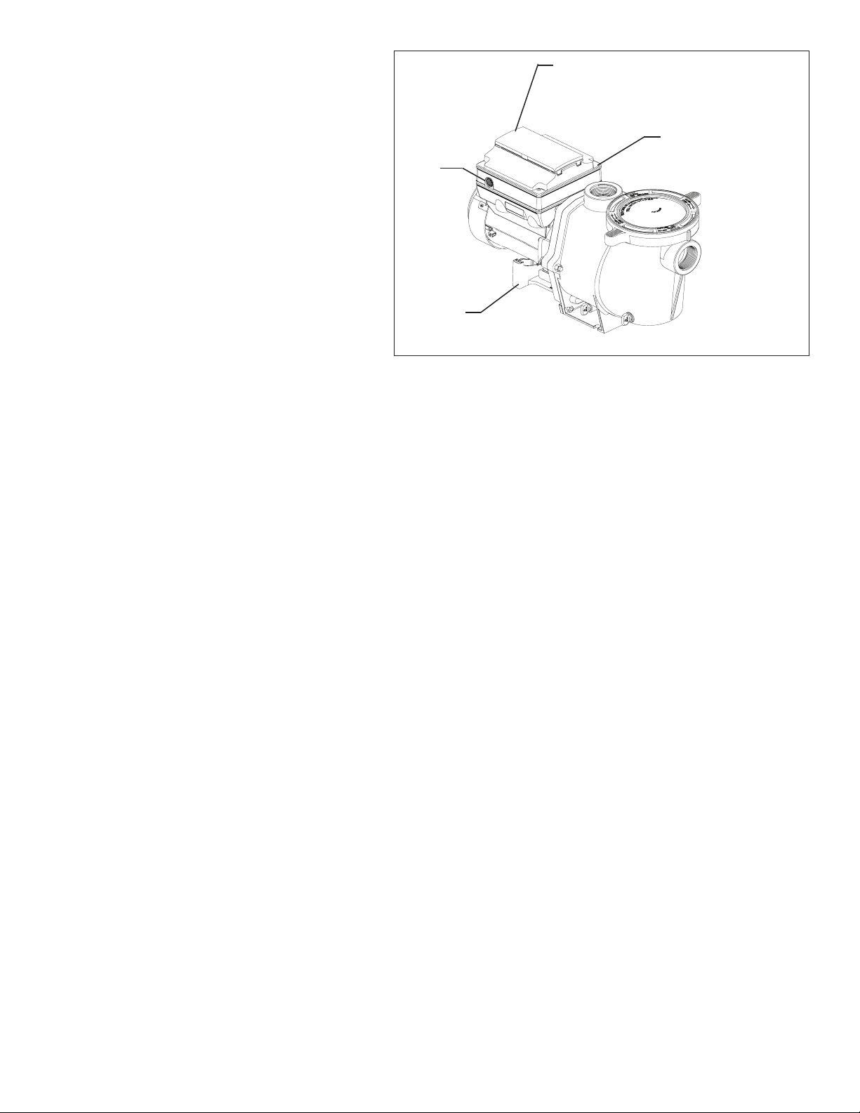
Drive Assembly and
Control Panel
The IntelliFlo® VS+SVRS Variable Speed Pump
drive is designed to produce maximum motor
operational efficiency. The drive controls the
motor’s rotational speed by controlling the
frequency of the supplied current. It also protects
the motor and pump from operating outside of their
intended operating parameters.
The control panel can be mounted on the pump
in four different directions in order to provide the
user the best access. The control panel can also
be mounted in a more convenient location with the
help of the keypad relocation kit (see "Optional
Keypad Relocation Kit" on the next page).
Strain
Relief
Port for
Incoming
AC Power
Motor
Stand
Operator Control
Panel Cover
Buttons and
LED (Beneath)
Communication port
for connection to
automation systems or
communication centers
via two-wire RS-485
cable (not shown)
Variable Speed Drive Assembly
INTELLIFLO® VS+SVRS and INTELLIPRO® VS+SVRS Variable Speed Pump Installation and User’s Guide
3
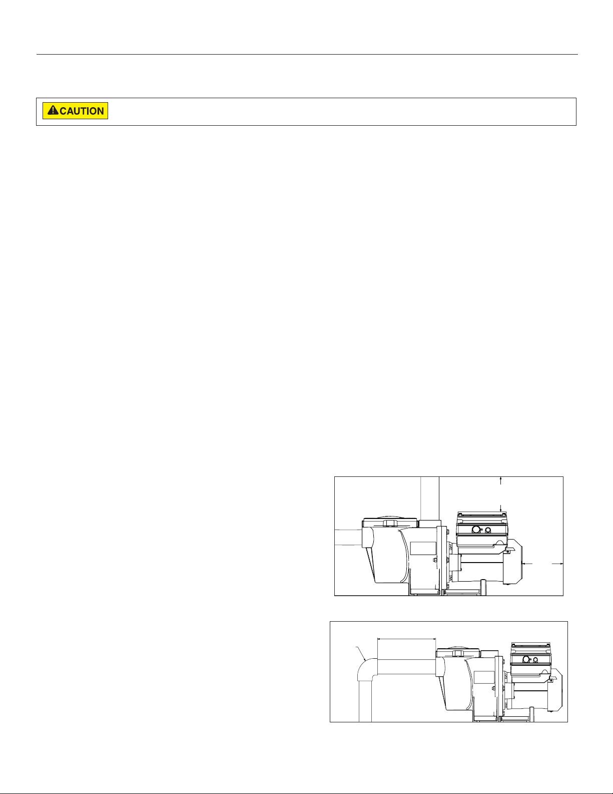
3 IN.
(7.6 CM)
MINIMUM
6 IN.
(15.2 CM)
MINIMUM
MIN 5 X SUCTION PIPE DIAMETER
ELBOW
INSTALLATION
Only a qualified plumbing professional should install the IntelliFlo® VS+SVRS Variable Speed Pump. Refer to “Important
Pump Warning And Safety Instructions” on pages ii - iv for additional installation and safety information.
The pump and its packaged components may have shifted during transport. When unpacking the pump at the installation site, carefully
remove the pump to avoid damaging it. Inspect the pump for any damage before beginning the following installation procedures.
Location
Note: Do not install this pump within an outer enclosure or
beneath the skirt of a hot tub or spa unless marked accordingly.
Note: Ensure that the pump is mechanically secured to the
equipment pad.
Be sure the pump location meets the following
requirements:
1. Install the pump as close to the pool or spa as possible.
To reduce friction loss and improve efficiency, use short,
direct suction piping returns.
2. Install a minimum of 5 feet (1.5 meters) from the inside
wall of the pool and spa. Canadian installations require
a minimum of 9.8 feet (3 meters) from pool water level.
3. Install the pump a minimum of 3 feet (0.9 meters) from
the heater outlet.
4. Do not install the pump more than 10 feet (3.1 meters)
above the water level.
5. Install the pump in a well ventilated location protected
from excessive moisture (i.e., rain gutter downspouts,
sprinklers, etc.)
6. Install the pump with a rear clearance of at least 3 inches
(76.2 mm) so that the motor can be removed easily for
maintenance and repair. See Figure 1.
Optional Keypad Relocation Kit
In special cases when the user lacks easy or convenient
access to the IntelliFlo VS+SVRS Variable Speed Pump, a
Keypad Relocation Kit (P/N 356904Z [Almond] or 356905Z
[Black]) may be purchased from your local pool equipment
supplier. This kit allows the user to remove the keypad from
the top of the drive and mount the keypad in a fixed location
with better access.
For installation instructions refer to the Keypad Relocation
Kit Installation Instructions provided with the kit.
Piping
1. For improved pool plumbing, it is recommended to use a
larger pipe size. When installing the inlet and outlet fittings
(male adaptors), use thread sealant.
2. Piping on the suction side of the pump should be the same
or larger than the return line diameter.
3. Plumbing on the suction side of the pump should be as
short as possible.
4. For most installations Pentair recommends installing a
valve on both the pump suction and return lines so that the
pump can be isolated during routine maintenance. We also
recommend a valve, elbow or tee installed in the suction
line should be no closer to the front of he pump than five
(5) times the suction line pipe diameter. See Figure 2.
Example: A 2 inch pipe requires a 10 inch (254 mm)
straight run in front of the suction inlet of the pump). This
will help the pump prime faster and last longer.
Note: DO NOT install 90° elbows directly into the pump
inlet and outlet.
5. When first starting the pump, confirm that the suction
pressure does not exceed 25 Inches of Mercury (inHg)
or 12.2 PSI. Run the pump at the highest speed with the
provided suction pressure gauge installed in the front
drain plug port on the pump strainer housing. The suction
pressure must be lower than 25 inHg or SVRS event
detection will not function properly.
Electrical Requirements
Figure 1: Pump Rear and Overhead Clearance
• Install all equipment in accordance with the National
Electrical Code and all applicable local codes and
ordinances.
• A means for disconnection must be incorporated in the
fixed wiring in accordance with the wiring rules.
INTELLIFLO® VS+SVRS and INTELLIPRO® VS+SVRS Variable Speed Pump Installation and User’s Guide
Figure 2: Recommended Piping
4
Fittings and Valves
1. Do not install 90° elbows directly into pump inlet.
2. Flooded suction systems should have gate valves installed on suction and discharge pipes for maintenance, however,
the suction gate valve should be no closer than five times the suction pipe diameter as described in this section.
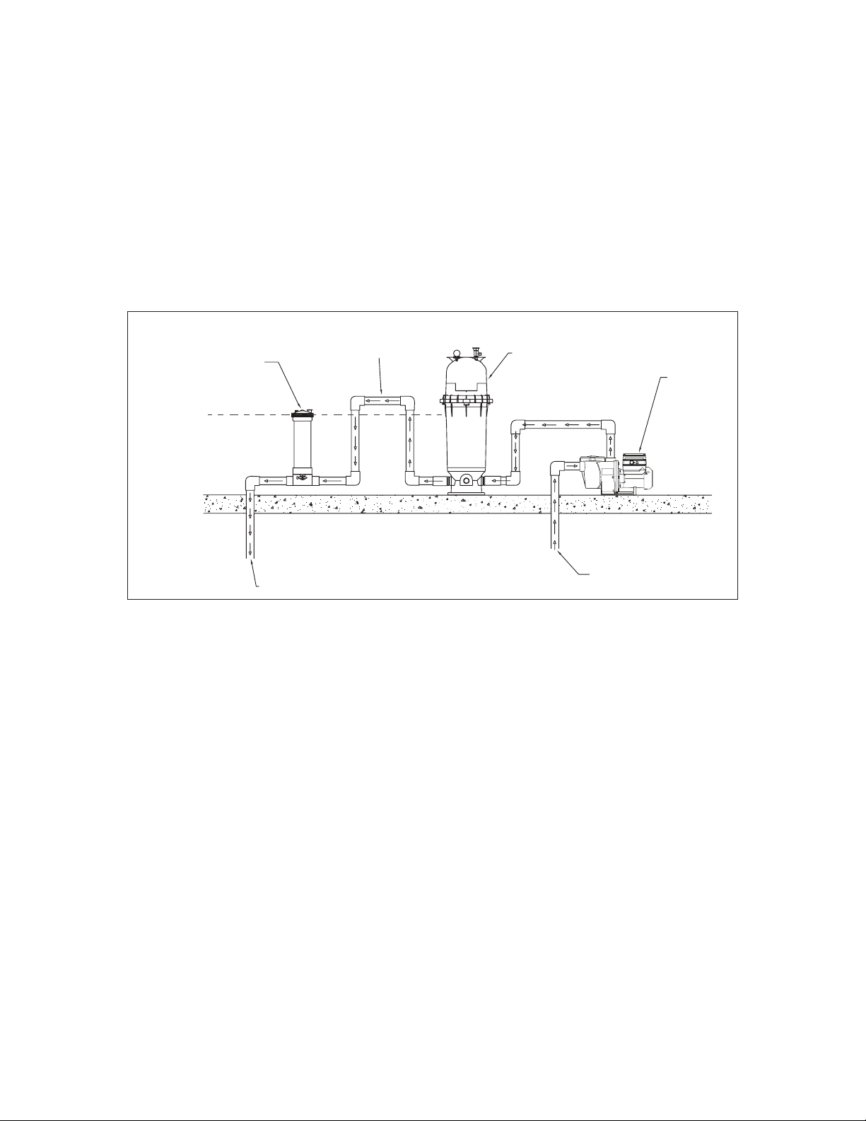
Check and Bypass Valves
Avoid the use of check or bypass valves in an SVRS equipped system. An operating check or bypass valve will cause changes
in system flow that the pump may interpret as a suction blockage event, resulting in consistent tripping and resets of the pump.
There are some cases where back-flow prevention is necessary, such as in systems where a chlorinator or heater is present.
Below are a few ways to control back-flow:
1. A Hartford loop can be installed in the system plumbing. A Hartford loop is a small section of plumbing that is built above
the highest point of the system's waterline. This loop causes the water head to equalize and prevents the water from
draining back into the filter and pump. See Figure 3 below for an example of this installation.
HARTFORD LOOP
(Loop’s peak is higher than
CHLORINATOR
CHLORINATOR
WATERLINE
the chlorinator’s waterline)
FILTER
POOL PUMP
TO POOL OR SPA
Figure 3: Example of a Hartford Loop Installation
FROM POOL OR SPA
2. If a check or bypass valve must be installed, the minimum speed will need to be set higher than the speed at which the
valve opens. This will prevent the pump from passing through the speed range that activates the valve. See page 10, Set
Minimum Speed (RPM) for instructions on setting the pump's minimum speed.
INTELLIFLO® VS+SVRS and INTELLIPRO® VS+SVRS Variable Speed Pump Installation and User’s Guide
5
Electrical Installation
RISK OF ELECTRICAL SHOCK OR ELECTROCUTION. This pump must be installed by a licensed or certified electrician or a qualified
service professional in accordance with the National Electrical Code and all applicable local codes and ordinances. Improper installation will
create an electrical hazard which could result in death or serious injury to users, installers, or others due to electrical shock, and may also
cause damage to property.
Always disconnect power to the pump at the circuit breaker before servicing the pump. Failure to do so could result in death or
serious injury to service people, users or others due to electric shock.
Read all servicing instructions before working on the pump.
Note: ALWAYS reinstall the drive lid onto the field wiring compartment when leaving the pump unsupervised during servicing.
This will prevent foreign matter (i.e. rainwater, dust, etc.) from accumulating in the drive.
Note: When connecting the pump to an automation system (IntelliTouch®, EasyTouch®, SunTouch® Control Systems and
IntelliComm® Communication Center), continuous power must be supplied to the pump by connecting it directly to the circuit
breaker. When using an automation system, be sure that no other lights or appliances are on the same circuit.
Wiring
1. Be sure all electrical breakers and switches are turned
off before wiring motor.
STORED CHARGE - Wait at least sixty (60)
seconds before servicing.
2. Be sure that the supply voltage meets the requirements
listed on the motor nameplate. If these requirements are
not met, permanent motor damage may occur.
3. For wiring sizes and general guidelines for proper electrical
installation, please follow the specifications defined in the
National Electric Code and any local codes as required.
4. Use strain relief and be sure all electrical connections
are clean and tight.
5. Cut the wires to the appropriate length so they do not
overlap or touch when connected.
6. Reinstall the keypad after wiring the pump by plugging
the cover back into the drive wiring connection and reseating the keypad in the desired orientation with the four
(4) corner screws.
Note: Ensure that the keypad cable is not pinched between
the drive and keypad during re-seating.
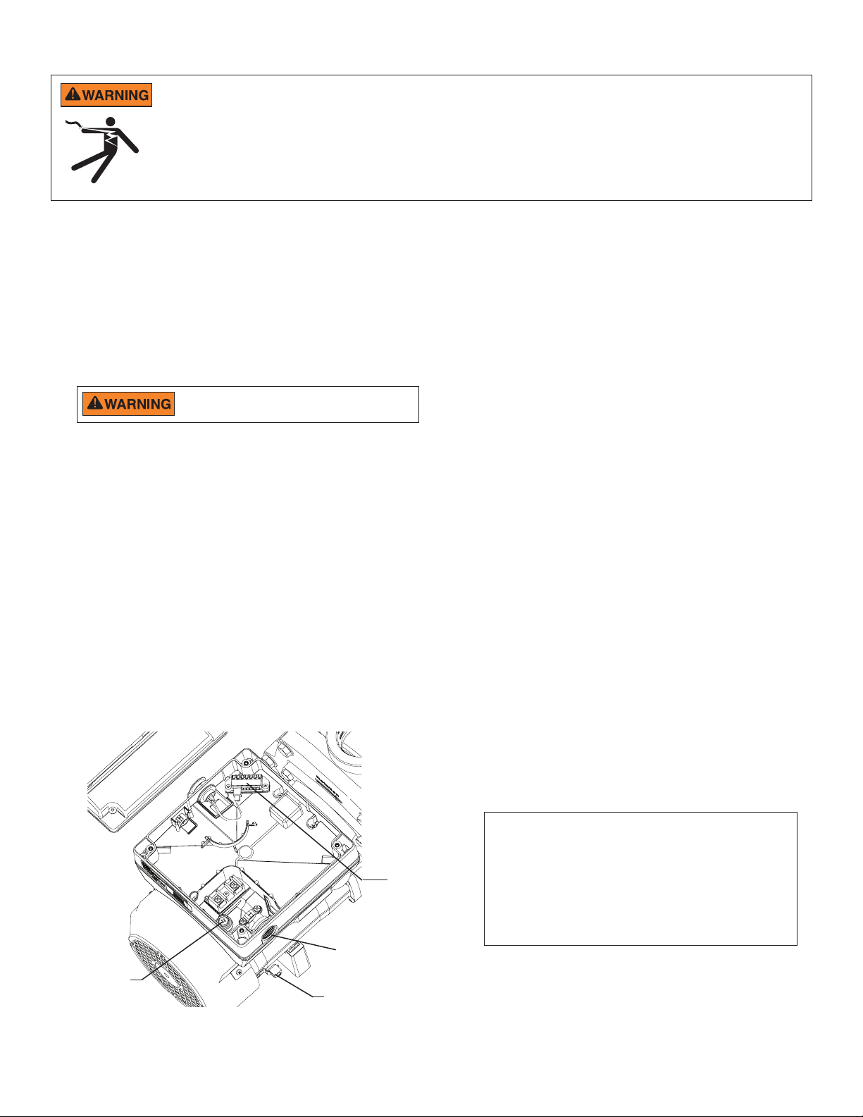
Grounding
1. Permanently ground the motor using the green ground
screw, as shown below. Use the correct wire size and
type specified by National Electrical Code. Be sure the
ground wire is connected to an electrical service ground.
2. The pump should be permanently connected to either a
circuit breaker, 2-pole timer or 2-pole relay.
Note: If AC power is supplied by a GFCI circuit breaker,
the pump should be wired on its own independent circuit
unless the pump is operated in tandem with a Pentair
salt chlorine generator.
Bonding
1. Bond the motor to the structure in accordance with the
National Electrical Code. Use a solid copper bonding
conductor not smaller than 8 AWG. For Canadian
installations, a 6 AWG or larger solid copper bonding
conductor is required. Run a wire from the external
bonding screw or lug to the bonding structure.
2. Connect the wire from the accessible bonding lug on the
motor to all metal parts of the swimming pool, spa, or
hot tub structure and to all electrical equipment, metal
conduit, and metal piping within 5 feet (1.52 meters) of
the inside walls of the swimming pool, spa, or hot tub.
Run a wire from the external bonding screw or lug to the
bonding structure.
Note: When the pump is started and stopped by removing
power with a relay or timer, a two-pole device should
be used to apply and remove power to both POWER
Drive Wiring
Connection
1/2” NPT
Conduit Port
Ground Wire
Connection
(Green Screw)
Field Wiring Compartment
INTELLIFLO® VS+SVRS and INTELLIPRO® VS+SVRS Variable Speed Pump Installation and User’s Guide
Bonding Lug
LINE TERMINALS.
Pentair offers 2-Pole 20 Amp GFCI breakers (P/N
PA220GF) which offer 6 milliamp personnel protection
while meeting 2008 to current NEC Standards for Pool
Pumps.
OPERATING THE PUMP
NOTE: Speed 1 is the default filtration speed.
NOTE: When setting up the IntelliFlo® VS+SVRS Variable Speed Pump, the user must set the pump’s internal clock and establish an
operation schedule by following the steps in this manual. Please refer to user’s guide sections: ‘Set Time’ (page 10) and ‘Set Speeds 1-8 in
Schedule Mode’ (page 13) to schedule a time to run the pump.
This pump is shipped with Priming mode ENABLED. Unless the Priming settings are changed in the menu, be aware that
the pump will speed up to the maximum speed when the pump is powered on for the first time, and the Start/Stop
button is pressed. To change the maximum speed of the pump, refer to page 10.
Before turning the pump ON, be sure the following conditions are met:
1. Open filter air relief valve.
2. Open valves.
3. Pool return is completely open and clear of any blockages.
4. Water in the pump basket.
5. Stand clear of the filter or other pressurized vessels.
6
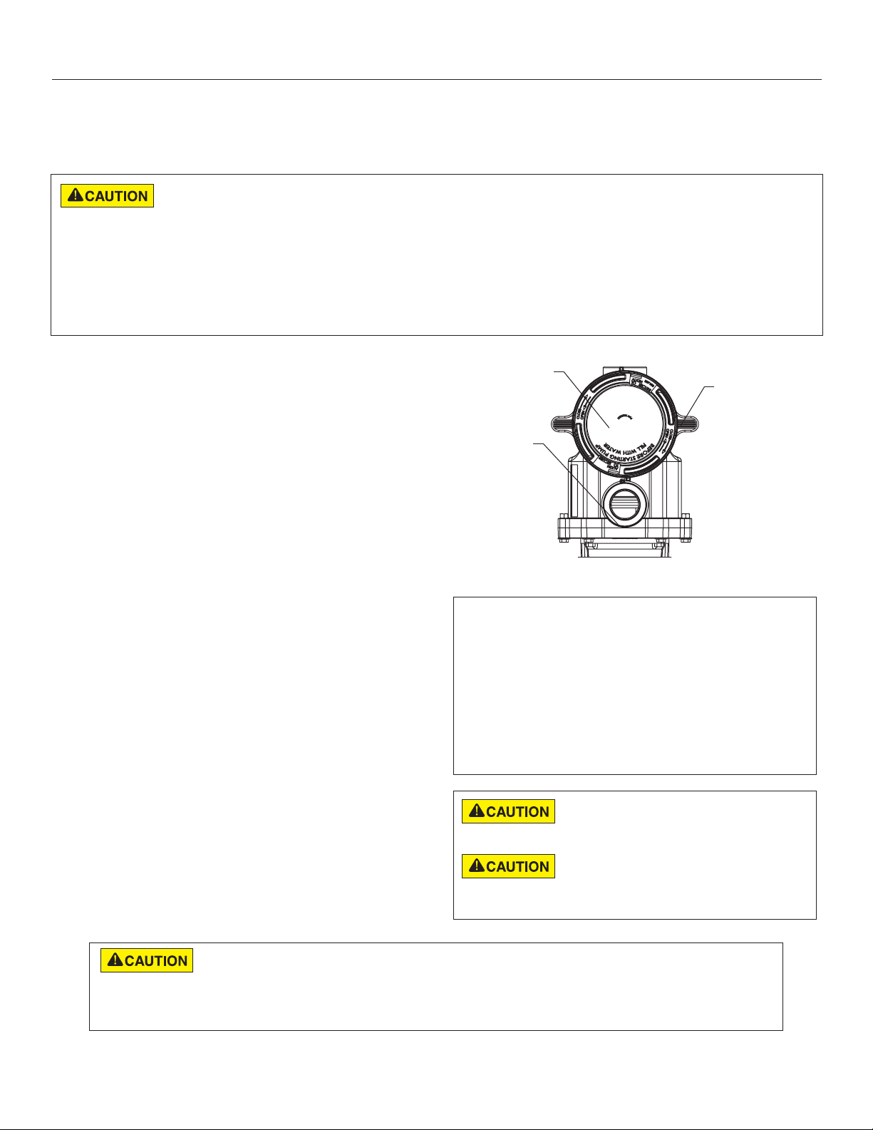
Priming the Pump
Prime the pump before starting the pump for the first time.
Remove the lid and fill the basket with water. The pump
basket must be filled with water before initial start up or after
servicing.
Follow the steps below to prime the pump for start up:
1. Press Start/Stop to stop the pump. Disconnect the
pump main power supply and communication cable.
2. Close all valves in suction and discharge pipes. Relieve
all pressure from the system.
3. Remove the pump lid and locking ring.
4. Fill the pump strainer pot with water.
5. Reassemble the pump lid and locking ring onto the
strainer basket. The pump is now ready to prime.
6. Open all valves in suction and discharge pipes.
7. Open the filter air relief valve and stand clear of the filter.
8. Connect power to the pump. Be sure green power light
is on.
9. Press Start/Stop to start the pump. The pump will enter
into priming mode (if enabled) and speed up to the
maximum speed set in the pump menu settings.
10. When water comes out of the filter air relief valve, close
the valve. The system should now be free of air and
recirculating water to and from the pool
11. Do not allow your pump to run longer than 30 minutes
time without developing full flow. If the pump does not
prime, check your priming settings on the control panel
or see the “Troubleshooting” section on pages 27-29.
Lid
Volute
Top View
Priming Features
The default priming setting is ENABLED. The pump
also allows you to set the following from the operator
control panel:
Locking
Ring
• Priming speed
• Priming range (1-10)
• Priming delay
Set up instructions on page 17.
Do not add chemicals to the system directly
in front of pump suction. Adding undiluted
chemicals may damage the pump and will void the warranty.
This is a variable speed pump. Typically the
lower speeds are used for filtration and heating.
The higher speeds can be used for spa jets, water features, and
priming.
DO NOT run the pump dry. If the pump is run dry, the mechanical seal will be damaged and the pump will start
leaking. If this occurs, the damaged seal must be replaced. ALWAYS maintain proper water level in your pool
(half way up skimmer opening). If the water level falls below the skimmer opening, the pump will draw air through the skimmer, losing
the prime and causing the pump to run dry, resulting in a damaged seal. Continued operation in this manner could cause a loss of
pressure, resulting in damage to the pump case, impeller and seal and may cause property and personal injury.
INTELLIFLO® VS+SVRS and INTELLIPRO® VS+SVRS Variable Speed Pump Installation and User’s Guide
7
12:15p
1100 RPM
1100 RPM
T 0.00 150 WATTS
Running Speed 1
SaveBack
Select
Menu
1
5
2
6
8
4
3
7
1 2 3
4
Quick
Clean
Time
Out
12:15p
1100 RPM
1100 RPM
T 0.00 150 WATTS
Running Speed 1
SaveBack
Select
Menu
1 2 3
4
Quick
Clean
Time
Out
15
Line 1
Line 2
Line 3
Line 4
9
13
12
10
11
14
Save?
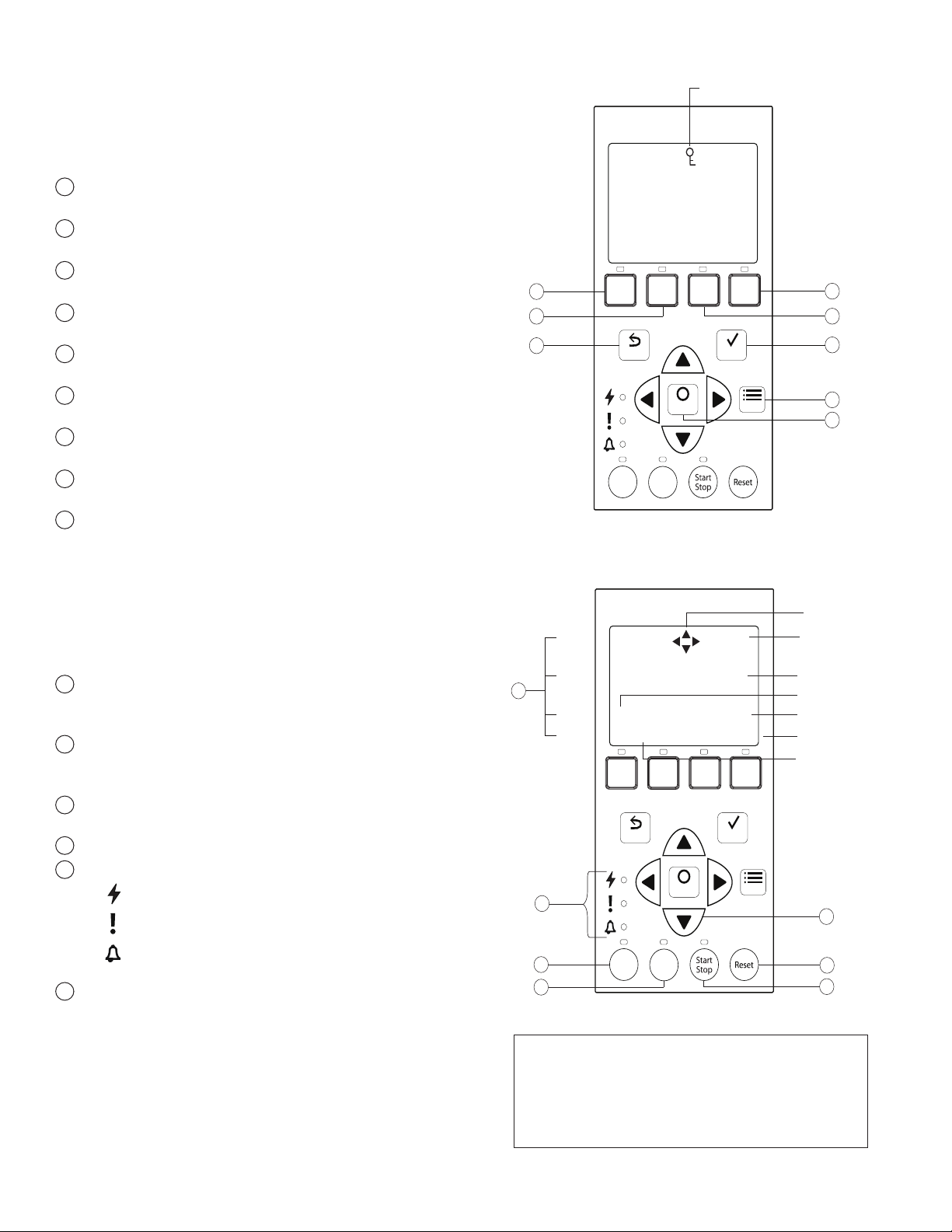
Using the Operator Control Panel
Use the operator control panel to start and stop the IntelliFlo®
VS+SVRS Variable Speed Pump, program, set, and change
speeds (RPM), and access pump features and settings.
Controls and LEDs on Keypad
Button 1: Press to select Speed 1 (1100 RPM). LED on
1
indicates Speed 1 is active.
2
Button 2: Press to select Speed 2 (1500 RPM). LED on
indicates Speed 2 is active.
Button 3: Press to select Speed 3 (2350 RPM). LED on
3
indicates Speed 3 is active.
Button 4: Press to select Speed 4 (3110 RPM). LED on
4
indicates Speed 4 is active.
5
Back: Goes one step back in menu; exits without saving
current setting.
6
Save: Saves current menu item setting. When a parameter
has been adjusted the "Save?" icon will be displayed.
7
Menu: Accesses the menu items when and if the pump is
stopped.
8
Select: Press to select the currently displayed option on
the screen.
9
Arrow buttons:
• Up arrow: Move one level up in the menu or increase
a digit when editing a setting.
• Down arrow: Move one level down in the menu or
decrease a digit when editing a setting.
Control Panel #1-8
• Left arrow: Move cursor left one digit when editing a
setting.
• Right arrow: Move cursor right one digit when editing
a setting.
10
Quick Clean: Pump increases to a higher RPM (for
vacuuming, cleaning, adding chemicals, etc.). LED light is
on when active.
11
Time Out: Allow the pump to remain in a stopped state for
a set period of time before resuming normal operation. LED
is on when active.
12
Start/Stop button: To start or stop the pump. When LED is
on, the pump is running or in a mode to start automatically.
13
Reset button: Reset alarm or alert.
14
LEDs:
On: Green light when pump is powered on.
15
Warning: On if warning condition is present.
Alarm: Red LED on if alarm condition occurs. See
“Alerts and Warnings” on page 27.
Control Panel LCD Screen:
• Line 1: Key icon indicates password protection mode is
Control Panel #9-15
active. If password protect is not enabled, no key icon
is displayed. Also shows current time of day. Active
cursors display when arrow key input is available.
• Line 2: Displays current pump speed (RPM).
• Line 3: Countdown time and watts
• Line 4: Current pump status and current feature. "Save?"
will display on this line when a parameter adjustment
can be saved.
Note: Always close the keypad cover after using
the keypad.
Note: Using screwdrivers or pens to program the
pump will damage the keypad overlay. Use your
fingers only when programming the pump.
Key Lockout Icon
Active Cursors
Current Time
Current Speed
Countdown Time
Current Power Usage
"Save?" Icon
Current Running
Feature
INTELLIFLO® VS+SVRS and INTELLIPRO® VS+SVRS Variable Speed Pump Installation and User’s Guide
 Loading...