

Pentair IntelliPool User Manual
INTELLIPOOL
INTP-1010B
MAESTRO
®
INTELLI
POOL
®
AUTOMATION
®
INTELLIPOOL
CONTROL
28/04/2017 15:23:48
Water temp. :+29.0°C
pH:7.8 ORP:607mV
Cond:5264uS 3.28g/l
ESC
VALID
1 2 3 4 5
INTELLIPOOL
PROBE UNIT
Water temperature
pH
ORP
Conductivity
pH
O.R.P.
®
English
Conductivity
INSTALLATION AND USER GUIDE
IMPORTANT SAFETY INSTRUCTIONS,
READ AND FOLLOW ALL OF THE INSTRUCTIONS,
KEEP THESE INSTRUCTIONS
PENTAIR WATER SOLUTIONS SB-CU-IMP-027J (Rev. 03/2019)
EN

A label with your condential codes is axed to the rst page of the cover.
This unique number (ID key) will be requested on creation of your free account (at www.intellipool.eu)
An internet connection is required to access the remote management account.

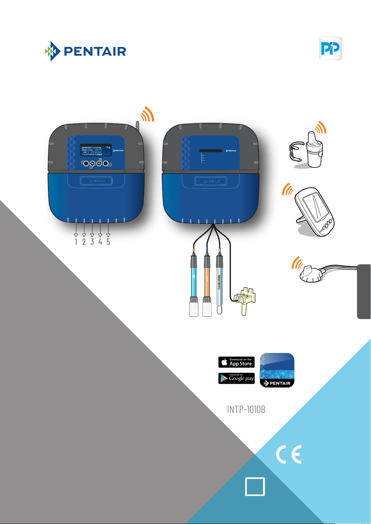
Pentair thanks you for placing your trust in the company and purchasing an INTELLIPOOL®, the set for water analysis and its off-board display environment, and remote monitoring
of your pool via the INTELLIPOOL® application from Pentair available in the App store and Play store.
The INTELLIPOOL® probe unit will permit you to learn about the main parameters which regulate the life of your pool and the INTELLIPOOL® Control Center will automatically regulate
your pool and permit you to control it remotely via the internet relay.
Please carefully read this user manual to fully benet from all of the functions of INTELLIPOOL®. Store it carefully so that it can be consulted at any time.
Declaration of conformity
Directives – Harmonised standards
Pentair International Sarl - Avenue de Sévelin 18 - 1004 Lausanne - Switzerland
We declare, under our own responsibility, that the product meets the directives
SAFETY EN 62368-1:2014
EMC EN 61326-1: EN 301 489-3
EMF EN 62311
RADIO EN 300 220-2
INTELLIPOOL (+ PARTS)
INTP-1010B
PART NUMBERS:
SB-SE-PRO-002C SB-SE-TEC-003A SB-CO-DIV-008B
SB-SE-PER-003C SB-SE-BBX-001B SB-SE-DOM-002A
Other normative documents Authorised person for technical documentation
Pentair International S.a.r.l
Avenue de Sévelin 18
1004 Lausanne - Switzerland
Lausanne, 01/04/2019
Guillaume Goussé
European Vice President of Operations
Product specications: INTP-1010B model
Operating temperature: 0 to 40°C Operating hygrometry: 40% AT 75°C Power supply: 230 V ~, 50 Hz
Maximum operating altitude: 2,000 m Weight (excluding sensors): 3.5 kg
Control Center + Probe Unit (internal use): IP 64 Radio relay (external use): IP 65 Internal display (internal use): IP 40
Internet relay (internal use): IP 20
Internet relay supply specications: 230 V/DC Jack 5.5/2.1 mm (external - negative): VEL05US060-EU-JA
Input : 100-240 V~50/60 Hz 0.18 A Output : 6.0 V 0.83 A max.
Waste treatment of electronic devices at the end of their service life:
The crossed-out bin placed on the main parts which make up the product indicates that it must not be disposed of with household waste. It must be returned to an
appropriate collection point for electronic device recycling (information available from the local household waste collection service). This product contains potentially
dangerous substances which may have adverse effects on the environment and human health.
Customer Support: PISA, ITALY (8:30 A.M. to 4:30 P.M.) CET website: www.pentairpooleurope.com
- Warranty (excluding sensors and consumables): 2 years
© 2019 Pentair International LLC, All rights reserved - The document is subject to change without notice
Trademarks and disclaimers: IntelliPool® and Pentair® are trademarks and/or registered trademarks of Pentair and/or its aliated companies. Unless indicated otherwise, names
and brands of others that may be used in this document are not used to indicate an aliation or endorsement between the owners of these names and brands and Pentair. Those
names and brands may be the trademarks or the registered trademarks of these parties, or others.
SB-CU-IMP-027 J
1

IMPORTANT SAFETY GUIDELINES, READ AND FOLLOW ALL OF THE INSTRUCTIONS, KEEP THESE INSTRUCTIONS
GENERAL POINTS
- DANGER - INSTALLERS, POOL SPECIALISTS AND OWNERS MUST CAREFULLY READ THESE WARNINGS AND ALL INSTRUCTIONS BEFORE USING
THIS PRODUCT.
- WARNING - Most countries regulate the construction, installation and operation of public swimming pools and spas, and the construction of residential pools and spas. It is important
to comply with these regulations, many of which directly regulate the installation and use of this product. Consult your local building and health codes for more information
- CAUTION - This installation and user guide contains important information on the installation, operation and safety of this product. This guide should be provided to the owner
and/or user of this product.
INSTALLATION
- DANGER - RISK OF ELECTRIC SHOCK or electrocution
- BEFORE WORKING ON THIS DEVICE - Always cut the supply to the device at the circuit-breaker before maintenance. Failure to do this may lead to death or serious injury to
service staff, pool users or others, due to an electric shock.
- DANGER - SERIOUS BODILY INJURY OR DEATH CAN RESULT IF THIS PRODUCT IS NOT INSTALLED AND USED CORRECTLY.
- WARNING - Before installing this product, read and follow the warnings and instructions of this guide. Failing to follow these warnings and instructions may lead to serious
injuries, death or material damage. Refer to www.pentairpooleurope.com for more information linked to this product.
- WARNING - Connect the device to a differential interrupter. If this system is used to control the underwater lighting devices, a differential interrupter must be installed upstream
of these devices. Conductors downstream of the differential interrupter shall not occupy conduits, junction boxes or enclosures containing other conductors, except if the
conductors are also protected by a differential interrupter. Refer to valid local codes for more details.
- WARNING - This product must be installed by an authorised or certied electrician or a qualied swimming pool professional. All of the applicable installation codes and local
regulations must also be respected. Poor installation will create an electrical hazard which could result in serious injury or the death of pool users, installers or others due to
electric shocks, and may also cause damage to property.
- DANGER - DISCONNECT THE SUPPLY CONNECTIONS BEFORE WORKING ON THIS DEVICE; ELECTRICAL POWER MAY BE SUPPLIED TO THE RELAY TERMINALS FROM OTHER SOURCES.
- CAUTION – CHEMICAL BURN HAZARD: Make sure all pumps are switched off at the main circuit breakers at the domestic distribution board before drilling into any pipes. Set
rules for all handling related to electrical aspects, water and chemical products. Group the supply pumps and chemical product tanks in a safe and secured area.
- CAUTION - Do not use this product to control an automatic swimming pool cover. There is a risk that swimmers could become trapped under the cover.
- CAUTION – Devices which are not intended for use in single-family dwellings may require additional safety equipment to comply with local regulations.
- WARNING – Except for remote controls, install components at a minimum of at least 1.5 m (5 feet) from the inside wall of the pool or spa.
- WARNING - This product is intended for use in swimming pool applications only.
- CAUTION - A sucient equipotential connection (min. 4.5 mm2 recommended), in accordance with local regulations, is obligatory for all metal components of the swimming
pool, including the pool pump. This is necessary for the electrical safety as well as reduction of the corrosion risk.
.
USE
- DANGER - DO NOT LET CHILDREN OPERATE THIS EQUIPMENT.
- CAUTION – Strictly respect the safety and handling procedures from the acid manufacturers, including protective measures for hands, body and eyes during transferring and
using acid. Follow the prescribed safety precautions for handling muriatic acid intended for checking the water pH. Muriatic acid may cause serious physical harm and may
damage the swimming pool equipment. Extra care must be taken when installing, maintaining and operating the acid pump feed systems. Acid is dangerous to handle and should
be properly contained, transported, poured, stored and dispensed.
- CAUTION – Check the pH and sanitizer levels of the water before using the pool and make sure the ltration device is not obstructed.
- CAUTION – Periodically use an independent pH and chlorine testing kit to ensure that the pH and chlorine is at a safe level. If the pH and Oxidation Reduction Potential (ORP) or
conductivity probes are broken, depleted or dirty with oils, lotions, or other contaminants, they can report inaccurate results to the system causing incorrect water chemistry,
which could harm people or equipment.
- CAUTION – Consult the device display daily to ensure there are no alarm messages.
- DANGER – Water temperatures greater than 37.7° C (100° F) are a health hazard. Prolonged immersion in hot water may induce hyperthermia. Hyperthermia occurs when the
internal body temperature exceeds the normal temperature of 37° C (98.6 °F) by several degrees. Hyperthermia may produce the following effects: (1) Unawareness of impending
danger. (2) Failure to perceive heat. (3) Failure to recognise the need to leave the spa. (4) Physical inability to leave the spa. (5) Harm to the foetus in pregnant women. (6)
Unconsciousness leading to the risk of drowning. The use of alcohol, drugs or medicine is a factor which increases the risk of hypothermia in hot tubs and spas.
- WARNING - When mixing acid with water, ALWAYS ADD THE ACID TO THE WATER. Never add water to the acid. When adding a chemical product to the swimming pool, carefully
follow the manufacturer instructions.
- DANGER - DO NOT MIX SODIUM HYPOCHLORITE AND MURIATIC ACID.
- DANGER - Keep standard solutions away from children, ensure that the bottles are securely closed, store them in a dry and ventilated location and do not let them freeze. The
pH 4 calibration solution is acidic.
- DANGER - Batteries may contain dangerous substances. They should not be thrown into the bin, opened, thrown into re or recharged, as there is a risk of explosion. Dispose of
the batteries in accordance with the manufacturer instructions. There is a risk of explosion if the battery is replaced by an incorrect type of battery. Handle a leaking battery with
gloves. Remove the batteries if the device is not used for an extended period of time.
- DANGER - The remote control contains a CR2032 button battery. Do not ingest the battery. In the case of ingestion, the battery or button accumulator may cause severe internal
burns which can be fatal within just 2 hours. Store new and used batteries out of the reach of children. If the battery compartment does not close in a safe manner, stop using
the product and keep it out of the reach of children. If you suspect that a battery has been ingested or introduced into any part of the body, seek a medical opinion immediately.
- DANGER - UV index information is supplied for information only and depends on the orientation and exposure of the radio relays.
For more information, we advise you to consult your dermatologist to inform you of the risks linked to your skin type.
English
2

Summary
PRESENTATION
> IntelliPool® characteristics
> Content of packaging
> General operation
> IntelliFlo® default settings
INSTALLATION
> Internet relays
> Probe Unit
> Control Center
> Electrical connections
> Radio relays
> Control Center menus
> Create an account at www.IntelliPool.eu
USE
> www.intellipool.eu menus
> Reading messages on the indoor display
OPTIONS & MAINTENANCE
> Adding a second radio relay
> Re-programming the original indoor display
> Adding a supplementary display
> Calibration of a pH sensor
> Calibration of a RedOx/ORP sensor
> Correction of values from the IntelliPool account
> Probe Unit: How to update the internal rmware
> Control Center: How to update the internal rmware
> Probe Unit: cleaning of pH and ORP probes
> Spare parts
p 3
p 4
p 5
p 5
p 6
p 7
p 9
p 10
p 15
p 17
p 23
p 24
p 29
p 33
p 34
p 34
p 37
p 38
p 40
p 41
p 42
p 43
p 44
3
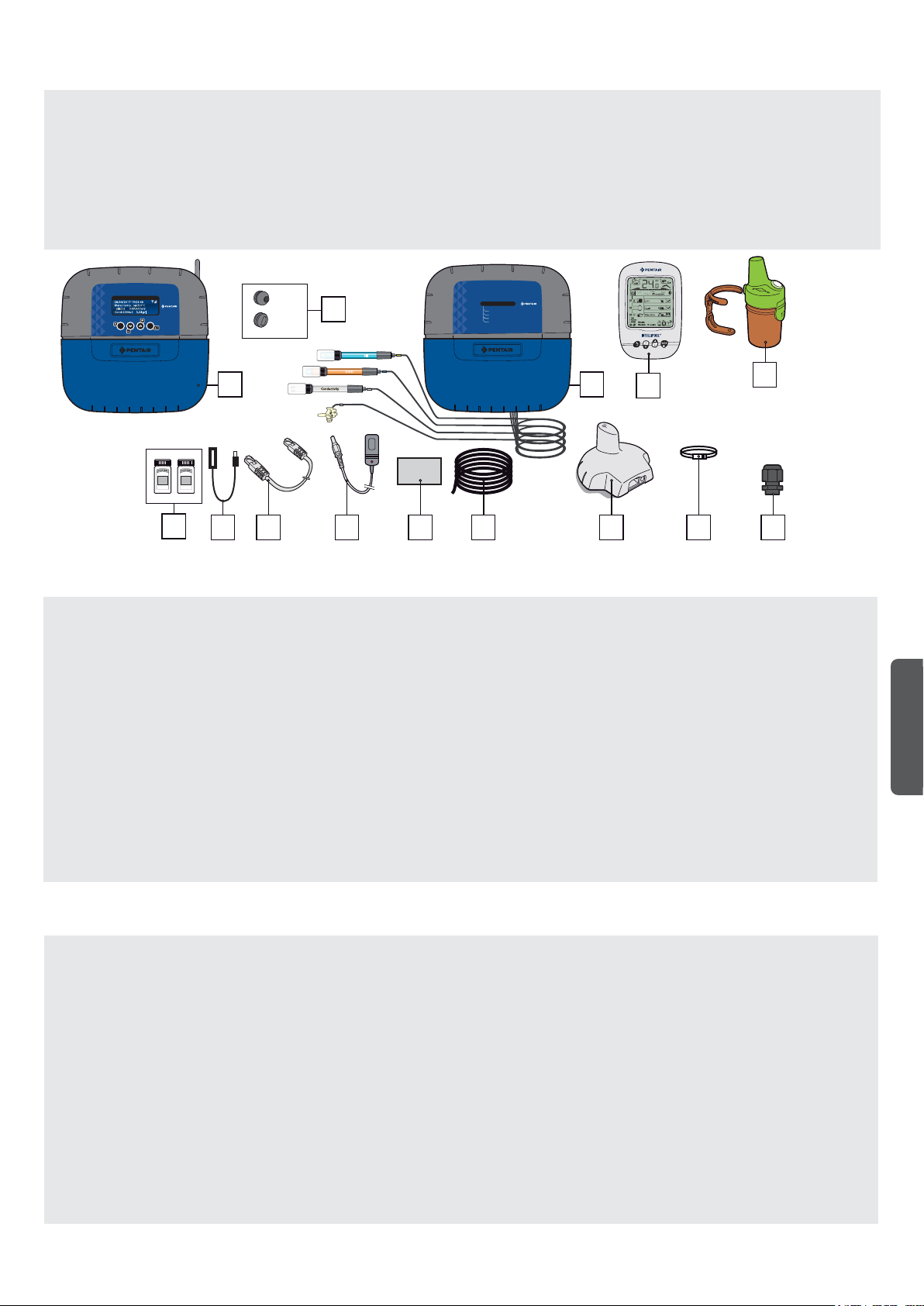
Content of Packaging
1 - Control Center 2 - Seals for electrical connections
3 - Probe unit (and its 4 probes supplied separately) 4 - Internal display
5 - Radio relay
6 - pH calibration solutions 7 - Female USB cable/mini USB (Probe Unit update)
8 - RJ45 cable 9 - power supply of the internet relay (110 V/230 V compatible)
10 - 8 x AA ProCell batteries (resistant to +70 °C) 11 - IntelliComm communication cable®
12 - Internet relay 13 - Webbed strip, 50/70 mm diameter, for the temperature sensor
14 - 3 strain relief bushings, 12 mm diam., for pH/ORP/Conduct. probes
®
INTELLIPOOL
CONTROL
28/04/2017 15:23:48
Water temp. :+29.0°C
pH:7.8 ORP:607mV
Cond:5264uS 3.28g/l
ESC
VALID
4 7
6
x11
x7
1
7 8 9 12 1311
2
pH
O.R.P.
Conductivity
8 x AA
10
INTELLIPOOL
PROBE UNIT
Water temperature
pH
ORP
Conductivity
®
3
4
5
x3
x3
14
Introduction
Your new IntelliPool ® system will provide fully automated management to your pool system. It controls and manages the water quality and permits
remote access to all the comfort functions of your pool for you and/or your professional. The result is a safer pool.
IntelliPool® will also be able to make substantial savings in terms of operation of your pool. Its unique control of IntelliFlo®, a variable speed pump,
assures the lowest possible consumption of power while maintaining the water quality with optimal filtration. These savings can be as much as
90%. Automatic control also reduces the use of chemical products and makes it possible to extend the life of a salt chlorinator.
IntelliPool® will also be able to adapt the filtration, disinfection and other functions while the pool is covered.
The increased convenience of using your pool will be the aspect of IntelliPool ® that you appreciate the most. The lights, heating and filtration can
be checked anywhere, at any time, by using any smartphone, computer or tablet. Automatic backwash is possible by using a specific valve on the
filter.
IntelliPool® uses precision and control sensors. Please follow the recommendations described in this manual and use professional help to install
your system.
The only thing now is to install your pool and enjoy it!
English
IntelliPool® functions
IntelliPool® manages the variation speed of IntelliFlo® according to: Water temperature/Position of the pool cover/Specific functions (waterfalls,
heating, IntelliChlor®)
- Optimisation of the IntelliFlo® rotation speed
- Modes: Automatic/ON/OFF/Schedule
- Disinfection based on the RedOx (ORP) measurement
- pH monitoring and dosing (pH + or pH-) including empty tank information
- Measurement of the conductivity to communicate the salt concentration
- Control of heating and setting of the temperature
- Lighting ON/OFF, clock mode and selection of IntelliBrite® colours
- Auxiliary outlet: - Automatic backwash (with push/pull valve) - accessory function (with a second pump or a 3-way valve) -
- ON/OFF mode, clock
All these characteristics can be accessed directly from IntelliPool® or from a smartphone/tablet
4
PROBE UNIT
REDOX -
PH
TEMPERA-
ESC
ENTER
CONTROL
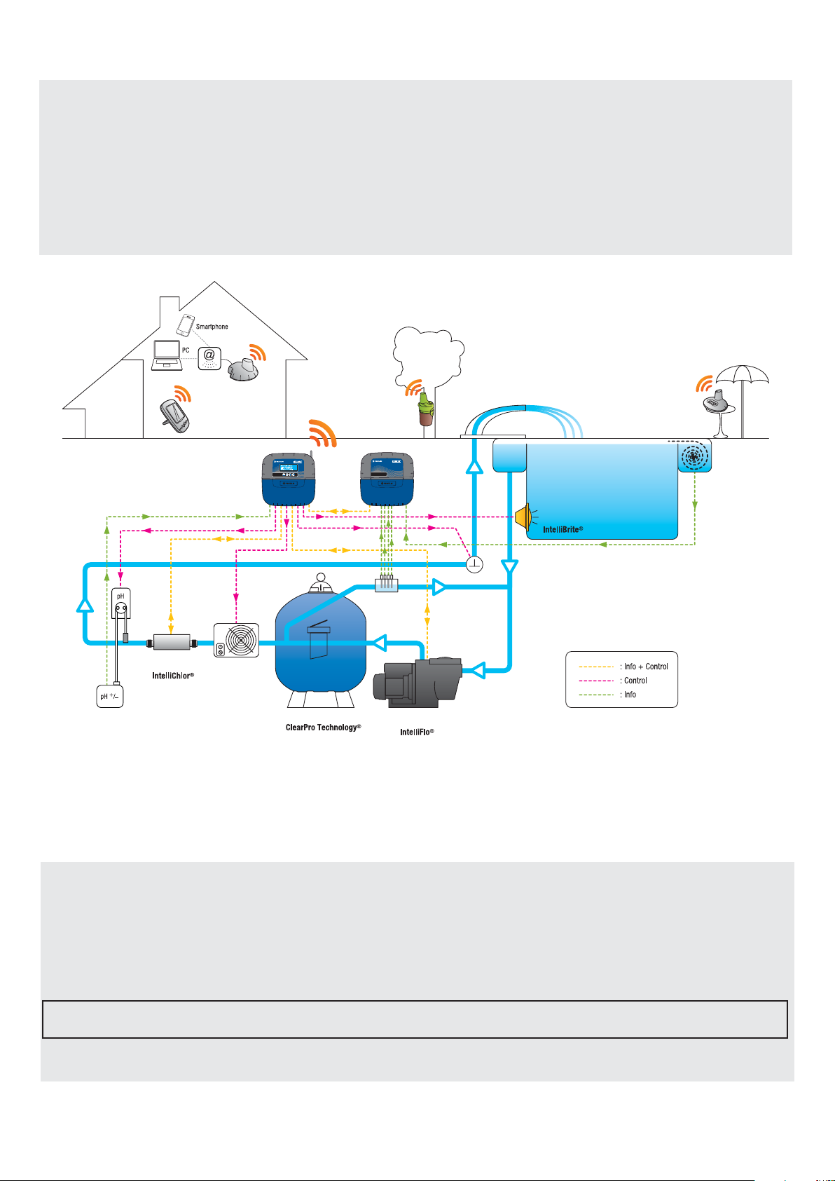
General operation
The PROBE UNIT, located in the technical room, collects information on the water quality and communicates this to the CONTROL CENTRE.
The CONTROL CENTRE is also located in the technical room and activates different equipment in the pool. For IntelliFlo® and IntelliChlor®, this
information is sent via a RS485 bus. In this way, IntelliPool® also collects information and comments from IntelliPool® and IntelliChlor®. By using
a wireless proprietary protocol at the centre of the control, it sends and receives information and controls from the other system component. The
INTERNET RELAY permits remote access to a system, using a PC, tablet or smartphone. The INTERNAL DISPLAY informs the pool owner of the
main pool parameters while the REMOTE CONTROL permits the lights and water feature to be activated in terms of pool aspects. The RADIO
RELAY assures radio communications between the elements, while collecting the temperature of the ambient air. In this configuration, the system
has all necessary elements to assure proper functioning of the pool.
12/07/2013 15:23:48
Water temp:+24.0°C
pH:7.3 ORP:629mV
Cond:5571uS 3.51g/l
Specific settings for the VSD drive and VSF IntelliFlo
The IntelliFlo® VS and VF pumps do not require specific settings.
However, for IntelliFlo® VSD, be sure to:
- Disable the freezing prevention function in the pump
- Set the minimum and maximum speeds at the same values as in the IntelliPool® menu to manually obtain similar protection during functioning of
the pump.
- Determine if you would like the priming function to be activated. Consult the VSD and VSF manual for this function. When it is activated on the
pump, the pre-programmed priming becomes active. Note that this can lead to unintended results with some equipment.
Please note: IntelliPool® will also control the pump keypad; stopping the pump from the keypad is not possible when IntelliPool® is
active. Use IntelliPool® or in an emergency, actuate the main power interrupter to stop the pump.
5
Internet relay - your pool is accessible 24h/day at www.intellipool.eu
The internet relay makes it possible to remain in contact with the installation via the internet (even if the home computer is switched off). Whatever
your type of computer (PC or MAC), you have access to real time data and can also work on the settings and commands.
Simply connect the internet relay to your internet "box" and connection to the Pentair server is automatic. By following the instructions, and after
creating your free account at www.intellipool.eu, you can connect to your installation in a few minutes.
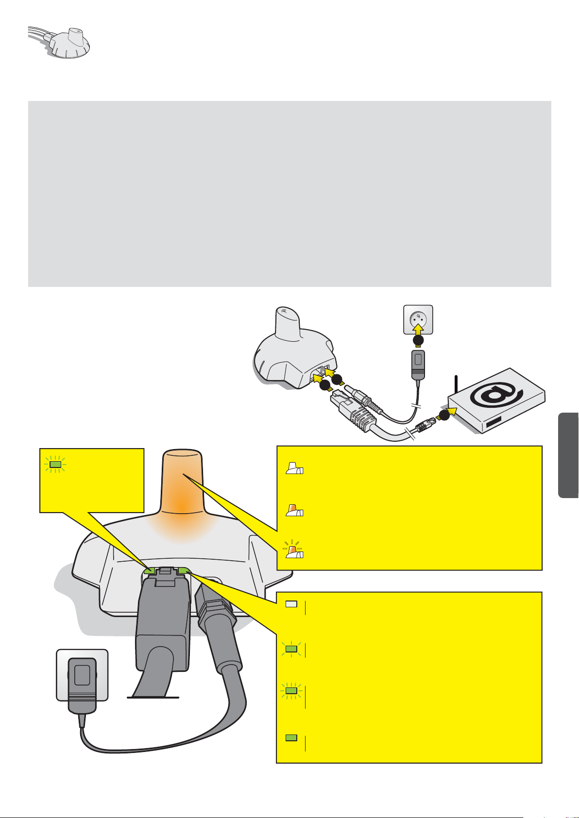
1 - Connect one end of the supplied Ethernet cable to the Ethernet port of your internet relay. Then connect the other end of the Ethernet cable to
a free Ethernet port of your box or ADSL modem. The supplied Ethernet cable can be replaced by an equivalent cable with a maximum length of
100 m. If you do not have a free Ethernet port on your "box" or ADSL modem, we advise you to obtain an Ethernet switch to permanently connect
your installation. 2 - Power the internet relay by connecting it only to the supplied mains supply.
The internet relay is automatically configured, provided the DHCP server of your internet "box" is activated (in the vast majority of cases, the DHCP
server is activated by default on installation of your internet "box"). This function can be accessed via the management menu of your internet "box",
refer to your internet access supplier for more details. Check that the internet relay works properly with the LED on the device (see the illustration
below).
2
Transmission of data in
progress
2
1
1
- Not lit = not connected to the server
> Check the power supply, connection of the Ethernet cable and the internet
connection.
- Lit = connected to the server
- Flashing = sending data in progress
- Off = Initialisation fault or no supply
> Check the connection of the 230-V supply.
- Slow blinking = no network
> Check the connection of the Ethernet cable and check the internet connection.
English
- Quick flashing = DHCP resolution in progress
> Takes less than a second. If the flashing continues, check the activation of the
DHCP in the management interface of your internet "box"
Light is permanently lit = network connection
> The internet relay is connected to the network.
6

Probe Unit
The Probe Unit, via its probes, measures the pH, ORP (RedOx), conductivity and water temperature. This information is sent to the Control Center.
The length of cables is voluntarily limited to 50 cm to ensure good probe reading precision.
1: Elastomer cover (Watertight protection) 2: Screw cover (protection against entry of vapours)
3: pH probe (0.5 m cable length) 4: ORP probe (0.5 m cable length)
5: Conductivity probe (0.5 m cable length) 6: Water temperature probe (2 m cable length)
7: Identification tag 8: Pool ID label, access codes to an internet account
The cap of the conductivity probe may not
be used for other probes.
The probe canisters must be filled with
potassium chloride or, failing this, running
water
INTELLIPOOL
PROBE UNIT
Water temperature
pH
ORP
Conductivity
7
INTP-1010B SB-SE-PRO-002C
®
QC Passed
Pentair International Sarl
Avenue de Sévelin 18
CH-1004 Lausanne, Switzerland
8
INTELLIPOOL
Pool ID: 12 345
ID Key: 1A:2B:33:99
S/N 1234ABCD1234ABCD1234ABCD01
24 V / IP64 / 2.4 W
MADE IN ITALY
Mfg Year
Apr-2019
SCAN
ME
Conductivity probe cap
Probe caps
with (with screw above) = probe out of the water
without = probe in the water
pH/ORP probe canister
Tighten/loosen the probe caps, never push or pull the fitted probe caps of the end
+24 V
RS-485
BUS BUS
1
pH CL
Radio
+24 V
RS-485
2
pH
ON
OFF
ORP
CONDUCT
pH
O.R.P.
Distilled
water
Conductivity
6
3
4
5
plug.
Installation and connection of probes
The Probe Unit must be installed close to the by-pass (the pH, ORP and Conductivity probes have 50 cm long cables)
1 -In the analysis chamber (recommended, Pentair ref. XXX), install the pH, RedOx and Conductivity probes in accordance with the diagram below. The glass
conductivity probe uses the gasket and the O-ring to ensure a perfect seal. The ORP and pH probes only use the O-ring.
2 - Install the temperature sensor outside of the analysis chamber (see the next page).
3 - Pass the cables through the white strain relief bushing, connect the cables in accordance with the markings, screw the strain relief bushing (see the next page).
®
INTELLIPOOL
PROBE UNIT
Water temperature
pH
ORP
Conductivity
- The probe cables must not cross the
power cable.
50 cm max.
- Pentair Analysis Chamber
pH
O.R.P.
Conductivity
Ref. INTP-HOLD-1.
- Limit the flow to fill the bowl (1L)
in 1 minute.
- The hydraulic network must be linked to the earth to prevent the
precision of the probes being altered.
3
4
1
2
- Assembly of the conductivity probe:
Pass the probe through the screw then, 1 - Slide the O-ring under the
probe holder, 2 - Slide the flat seal under the O-ring, 3 - Lower the
probe and probe holder to the contact, 4 - Screw the holder until a
perfect seal is formed after pressure tests.
- Assembly of pH and ORP probes:
Pass the probe through the screw then, 1 - Slide the O-ring under the
probe holder, 2 - Lower the probe and probe holder to the contact,
3 - Screw the holder until a perfect seal is formed after pressure
tests.
2
3
1
7
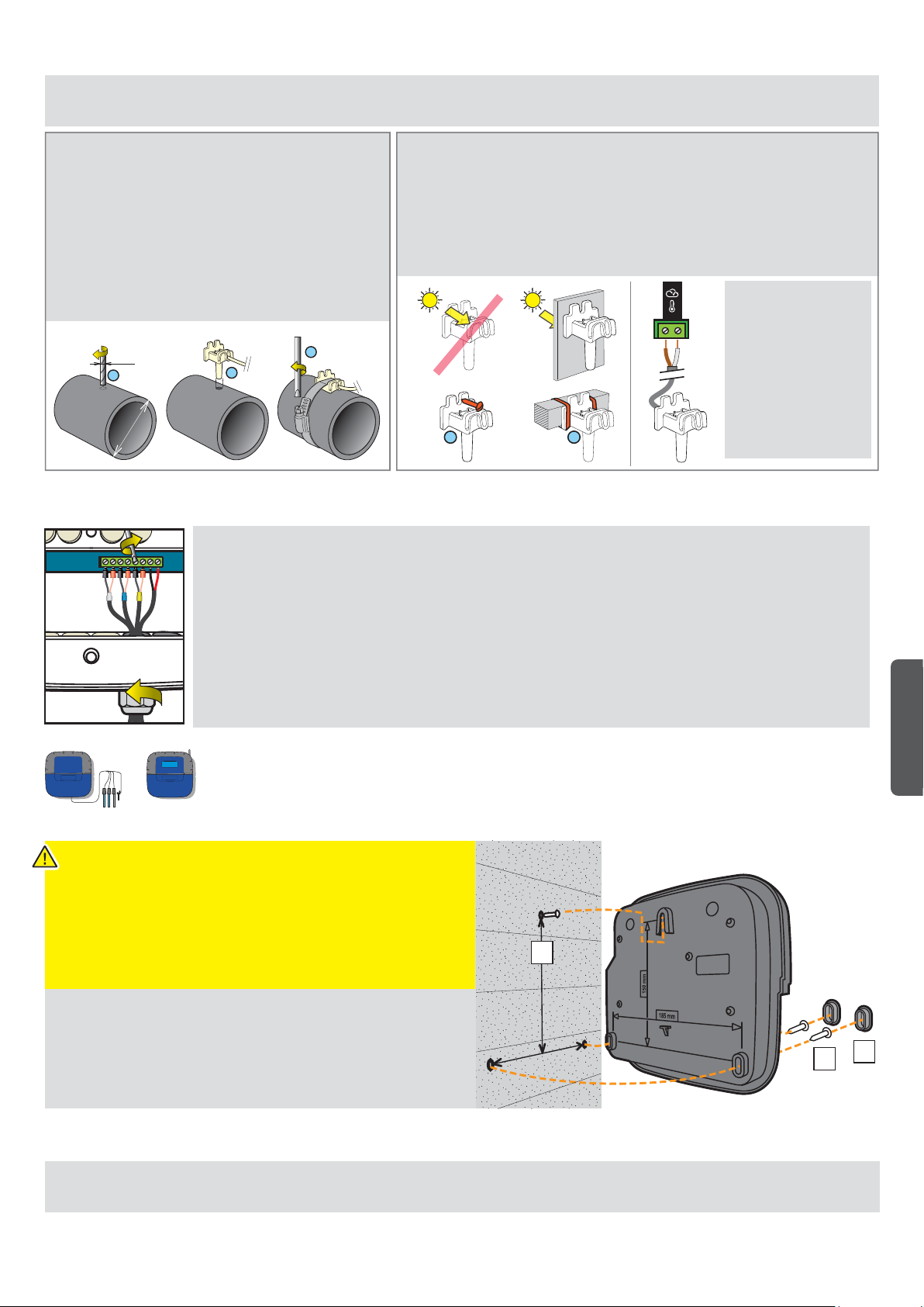
Installation of the water temperature probe
INTELLIPOOL is supplied with a temperature probe which is suitable for water. It is possible to mount a second temperature probe for the air
temperature used to manage the frost protection process of heated technical rooms.
The temperature probe can be installed outside the bypass
in front of the filter of the pump or in front of the filter inlet in
order to improve the reading precision. 1 - Pierce the PVC
pipe to a diameter of 10 mm (3/8 inch). 2 - Remove the
shavings and check that the O-ring is present under the
probe, place the probe in the hole. 3 - Place the metal clamp
in the groove and tighten.
Ø 10 mm
1
2
Ø 50/70 mm
3
INSTALLATION OF THE AIR TEMPERATURE PROBE (OPTION)
- If the air temperature probe is connected, it automatically becomes the reference
value for the management of the anti-freeze protection. The air temperature probe
is placed outdoors, away from direct sunlight so that the measurement is not
distorted. It can be easily moved due to its 6 m long cable.
1 – Mount it to a wall by screwing OR 2 – Mount it on a horizontal bar of a grate with
a cable tie.
Installation of pH/ORP/Conduct. probes
1 - Completely unscrew the strain relief bushing: be careful and do not let the black, flexible seal fall.
2 - Pass the cables through the nut and strain relief bushing
3 - Connect each lug according to the indicator under each terminal block
4 - Tighten using a 2.5 mm/0.5-0.6 Nm slotted screwdriver
5 - Securely re-tighten the strain relief bushing by hand
The service life of the probes (depending on the conditions of use) is around 2 years for the pH probe, 5 years for the
RedOx probe and a lifetime for the conductivity and temperature probes. Only Pentair probes are compatible and
guarantee proper functioning of the IntelliPool®.
TO ISOLATE THE BYPASS, CLOSING THE TWO VALVES BEFORE CHANGING A PROBE IS MANDATORY TO
PREVENT ANY RISK OF FLOODING.
NO OK
1 2
If an air temperature
probe is connected,
the air temperature
information from the
radio relay will no
longer be used.
English
Mount the Control Center/Probe Unit to a wall
- This device is intended to be used inside, installed in a technical room
which cannot be accessed by children.
- Set the device at a height lower than 2 m using three screws (4 to 5 mm
diameter) in appropriate plugs for the type of support and x the device
vertically on a clean support which is able to bear a minimum vertical load
of 5 kg.
Make three holes, with plugs, following the below dimensions.
1
m
m
0
5
1
1 - Place the upper screw and hang the device.
2 - Place the 2 lower screws.
m
m
5
3 - Add the 2 lower screw covers to ensure a full seal.
8
1
Placement of the Probe Unit and Control Center
The Probe Unit must be located close to the probe assembly bypass.
The Control Center must be located next to the electrical cabinet and its keypad must be accessible to easily perform settings.
8
3
2
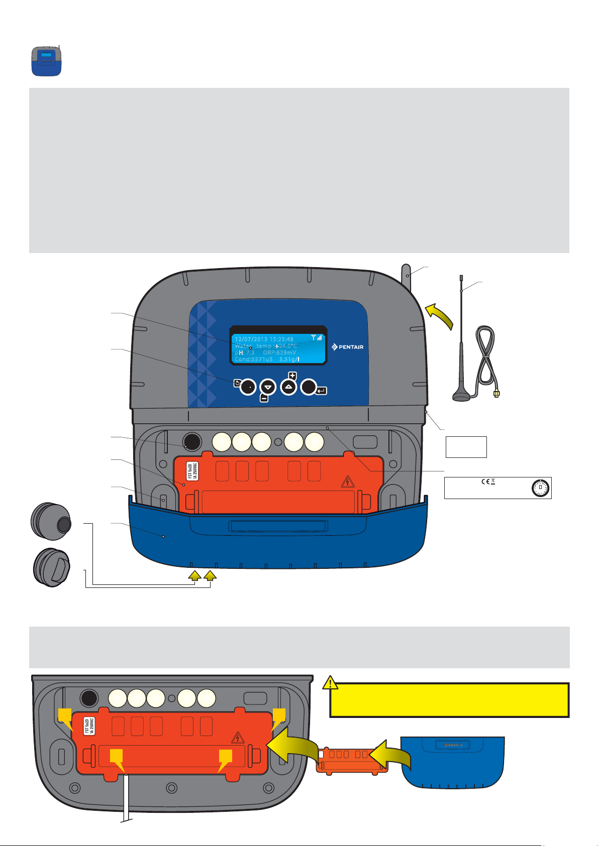
Control Center
It is the brain of the system. SOLEO calculates automatically and controls the operating time of each piece of the equipment.
It receives the orders via remote control or via internet and launches the lighting of the concerned device.
The activity is stored in internal memory for 64 days (can be consulted by the user).
1: Backlit screen (4 x 20 characters) 2: Buttons (navigation menu)
4: Fuse holder (1 A)
5: Connector cover (can be unclipped with a screwdriver) 6: Screw cover (protection against entry of vapours)
7: Rubber cover (Watertight protection) 8: Radio antenna
9: Off-board magnetic radio antenna (option) Ref.: INTP-5240 10: Identification tag
11: Cable grommet compatible for cables of diameters 7 mm to 10 mm, to be mounted with the supplied silicon lubricant. Avoid any vapour
entering the housing.
12: End plug to be assembled if an outlet is unused. Avoid any vapour entering the housing.
13: Pool ID label, access codes to an internet account
8
9
11
12
1
2
INTELLIPOOL
CONTROL
12/07/2013 15:23:48
Water temp :+24.0°C
pH: 7.3 ORP:629mV
Cond:5571uS 3.51g/l
ESC
4
®
VALID
13
INTELLIPOOL
Pool ID: 12 345
ID Key: 1A:2B:33:99
5
10
INTP-1010B SB-SE-TEC-003A
QC Passed
Pentair International Sarl
6
Avenue de Sévelin 18
CH-1004 Lausanne, Switzerland
S/N 1234ABCD1234ABCD1234ABCD01
230 V 50 Hz~ / IP64 / 16 W
433.445 MHz
MADE IN ITALY
Mfg Year
Apr-2019
SCAN
ME
7
Disassembly of the orange cover of the Control Center
To respect the current electrical standards, a safety cover which cannot be unclipped without a tool is positioned above the connectors which guide the voltage.
> Place a flat screwdriver on the flat part of clips 2 and 3, while keeping pressure on the cover to unclip it.
After each intervention, replace the orange safety
1
2
3
4
cover then the soft blue cover.
9
185 mm
150 mm
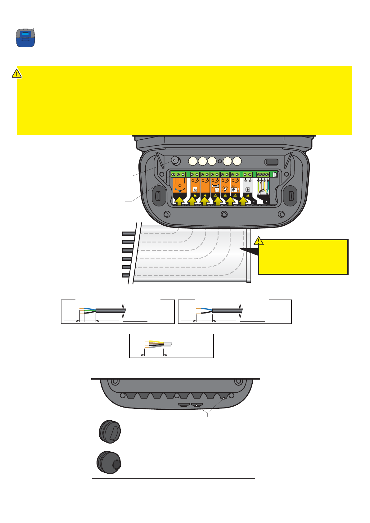
Control Center
Hygiene of Control Center electrical connections
- The device must be installed by a qualied technician according to valid local regulation
- This device is permanently connected.
- The power supply to the device is cut by its interrupter, which must be close and must remain accessible at all times.
- The device needs to be connected to the earth and its power supply needs to be protected by 16A 30 mA differential protection. This protection must
be cut before any intervention on the device.
- Overvoltage category II (2,500 V peak) electrical device. If necessary, place overvoltage protection equipment before the device.
- The device must be placed close to the electrical cabinet to aid connections (3 m max.).
Interchangeable fuse
FST 5x20 250 V AC 1 A fast
Screw terminals
Slotted screwdriver 2.5 mm/0.5-0.6 Nm
N L
230 V ~
pH
AUX1
CL
5-230 V~
BUS
24V
RS-485
OR
POWER SUPPLY 230 V / 50 Hz +- 10%
PH DOSINF PUMP - 230 V 10A max.
AUX 1 - 230 V 10 A max.
DISINFECTION - 230 V 10A max.
LIGHTING - 230 V 10 A max.
HEATING - 230 V 10 A max.
Compatible power supply cables 230 V
30 mm max. 5 mm
The supply cable as well as the cables of
the dry power contacts must be placed in
a plated and closed channel under the
device.
Compatible dry contact cables
= RO2V (3 x 1.5 mm2 min.) = RO2V (2 x 1.5 mm2 min.)
Ø 8/8.8 mm
30 mm max. 5 mm
Ø 8/8.8 mm
“BUS IN” (RS485) compatible cable
= VGV (4 x 0.75 mm2)
20 mm max.5 mm
BACK VIEW
10
Caps
- must be installed if an outlet is not in use
(to stop any humidity or acidic vapour entering)
Cable ducts
- must be installed if an outlet is in use,
(to stop any humidity or acidic vapour entering)
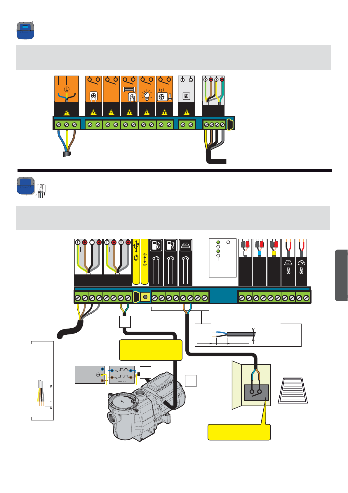
230-V connection and Probe Unit on the Control Center
The Control Center must be placed close to the electrical cabinet to aid connections (3 m max.).
Connect the 230 V. Connect the 230 V only at the end of connections.
Connect the BUS cable to the data and power points of the Control Center, on the Probe Unit.
N L
230 V ~
pH
AUX1
CL
5-230 V~
24V
OR
RS-485
BUS
230 V
Connections from the Probe Unit to the Control Center and from the pool cover
1 - Connect the 230 V.
2 - Connect the IntelliFlo ref 350122/10 m length cable supplied with IntelliPool
3 - Connect the green cable to Datas+ and connect the yellow cable to Datas-. Cables connected to RS-485 must remain within the building.
pH CL
Radio
+24 V
RS-485
+24 V
RS-485
BUS BUS
®.
ON
OFF
CONDUCT
ORP
pH
English
= VGV (4 x 0.75 mm2)
> Control Center
20 mm max.5 mm
“BUS IN” (RS485) compatible cable
230 V
NEUTRAL (N)
EARTH
PHASE (L)
3
Each cable of this type (Intelli
range) must be connected in
accordance with this principle.
1
Compatible dry contact cables
= RO2V (2 x 1.5 mm2 min.)
30 mm max. 5 mm
Ø 8/8.8 mm
2
Electrical cabinet
of the pool cover
Dry contact closed when the
cover closes off the pool
11
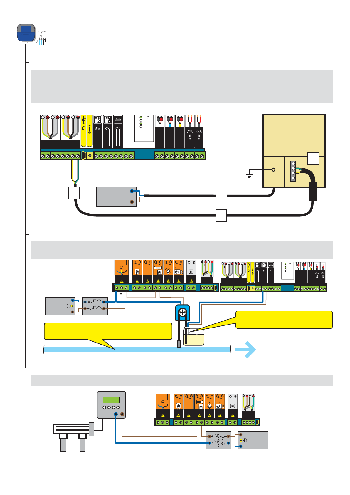
Connection of a disinfection system to the Probe Unit
Connection of an IntelliChlor salt chlorinator
1 - Connect the 230 V.
2 - Connect the IntelliFlo ref 350122/15-m cable supplied with IntelliPool
3 - Connect the green cable to Datas+ and connect the yellow cable to Datas-.
4 - Connect the green strand on terminal 2 and the yellow strand on terminal 3 of the IntelliChlor
pH CL
Radio
+24 V
RS-485
+24 V
RS-485
ON
OFF
BUS BUS
®.
pH
ORP
CONDUCT
® Power Centre.
Communication
centre
for IntelliChlor ®
1
2
3
4
3
NEUTRAL (N)
PHASE (L)
230 V
1
2
Connection of a liquid chlorine pump
1 - Connect the chlorine pump and the pH corrector level sensor as described below. Select “other” in the Settings/Install/Other menu, see p18.
pH
AUX1
CL
230 V
N L
230 V ~
NEUTRAL (N)
EARTH
PHASE (L)
The chlorine injection must be placed after filtration, after the heat pump
and after the probes.
5-230 V~
Chlorine
24V
BUS
RS-485
+24 V
RS-485
OR
+24 V
BUS BUS
Chlorine level sensor is normally open.
(Closed switch = empty tank)
RS-485
Radio
pH CL
ON
OFF
4
pH
ORP
CONDUCT
Connection to a conventional salt chlorinator
1 - Connect a conventional electrolyser as described below.
N L
230 V ~
12
pH
AUX1
5-230 V~
CL
24V
OR
BUS
PHASE (L)
EARTH
NEUTRAL (N)
RS-485
230 V
 Loading...