

Pentair INTELLIFLO WHISPERFLOVSD, INTELLIFLO SW5P6R VSD, INTELLIFLO ULTRAFLOW VSD, INTELLIFLO 5PXF VSD, INTELLIFLO WXF-VSD Installation Manual
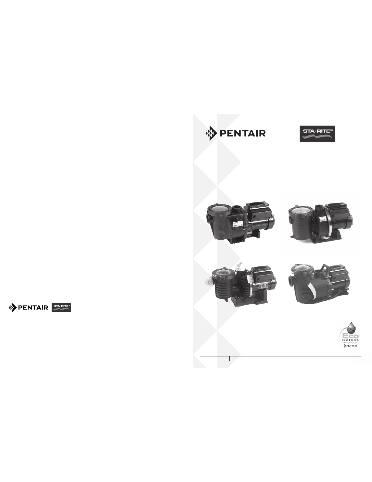
INTELLIFLO® WHISPERFLO® VSD INTELLIFLO® ULTRAFLOW® VSD
INTELLIFLO® SW5P6R™ VSD
P-INSB-VSD
INTELLIFLO® 5PXF™ VSD/
INTELLIFLO WXFVSD
INSTALLATION GUIDE / INSTALLATIEHANDLEIDING
BEDIENUNGSANTLEITUNG / GUIDE DE L’INSTALLATION
GUIA DE INSTALACION / GUIDE ALL’INSTALLAZIONE
SWIMMING POOL PUMPS
INTELLIFLO® VSD
INTELLIFLO
®
VSD VARIABLE SPEED PROGRAMMABLE PUMP
IMPORTANT SAFETY INSTRUCTIONS READ AND FOLLOW ALL INSTRUCTIONS SAVE THESE INSTRUCTIONS
WATER SOLUTIONS P-INSB-VSD (Rev. 08/2016)
Copyright – Limited License: except as specically permitted herein, no portion of the content on this document may be reproduced in any form or by any mean without the
prior written permission of Pentair International SRL.
Copyright – Eingeschränkte Lizenz: soweit hierin nicht ausdrücklich zugelassen, dürfen die Inhalte dieses Dokuments ohne vorausgehende schriftliche Genehmigung der
Pentair International SRL weder ganz noch auszugsweise und in gleich welcher Form und mit welchen Mitteln vervielfältigt werden.
Copyright – Beperkte licentie: behalve zoals hierin speciek toegestaan, mag geen enkel deel van de inhoud van dit document op om het even welke manier of hoe dan ook
gereproduceerd worden zonder de voorafgaande schriftelijke toestemming van Pentair International SRL.
Copyright – Licence limitée: sauf expressément autorisé ci-après, aucune partie du contenu de ce document ne peut être reproduite sous toute forme ou par tout moyen
sans la permission écrite préalable de Pentair International SRL.
Copyright – Licencia limitada: salvo en lo expresamente permitido en el presente documento, se prohíbe la reproducción total o parcial del mismo por cualquier medio sin
la previa autorización por escrito de Pentair International SRL.
Copyright – Licenza limitata: se non indicato specicatamente di seguito, nessuna porzione del contenuto di questo documento può essere riprodotta in qualsiasi forma o
con qualsiasi mezzo senza preventiva autorizzazione scritta di Pentair International SRL.
SAVE THESE INSTRUCTIONS !
PENTAIR AQUATIC SYSTEMS
INDUSTRIEPARK WOLFSTEE, TOEKOMSTLAAN 30, 2200 HERENTALS - BELGIUM, WWW.PENTAIRPOOLEUROPE.COM

© 2012 Pentair International LLC, All rights reserved
This document is subject to change without notice
Trademarks and disclaimers: IntelliFlo® and Pentair™are trademarks and/or registered trademarks of Pentair
and/or its afliated companies.Unless noted, names and brands of others that may be used in this document are
not used to indicate an afliation or endorsement between the proprietors of these names and brands and Pentair.
Those names and brands may be the trademaks or registered trademarks of those parties or others.
Customer Support
HERENTALS, BELGIUM (8:30 A.M. to 4:30 P.M.) CET
Website: www.pentairpooleurope.com
Declaration of Conformity
P-WFL-VSD
P-UFL-VSD
SW5P6R-VSD
5PXF-VSD
A sample of the equipment has been tested for -marking according to the following EC-directives.
- the Low Voltage Directive 2006/95/EC
Standards used for showing compliance with the essential requirements in the directive 2006/42/EC:
- EN60335-1
- EN60335-2-41
Manufacturer: Pentair
Industriepark Wolfstee
Toekomstlaan 30
B-2200 Herentals - Belgium
www.pentairpooleurope.com
IMPORTANT SAFETY INSTRUCTIONS
READ AND FOLLOW ALL INSTRUCTIONS
SAVE THESE INSTRUCTIONS

1
Installation and User’s Guide
ENGLISH
page 2 - 39
Montage- und Bedienungsanleitung
Installatie- en gebruikershandleiding
Manuel d’installation et d’utilisation
Istruzioni per l’installazione e l’uso
DEUTSCH
NEDERLANDS
FRANÇAIS
ESPAÑOL
ITALIANO
Seite 40 - 77
pagina 78 - 115
page 116 - 153
página 154 - 191
página 192 - 229
Guía de Instalación y del Usuario

Contents
2
Important Warning and Safety Instructions ....................................................................................... 4
Section 1: Pump Overview .........................................................................................7
IntelliFlo® VSD Pump ...............................................................................................7
External Control .......................................................................................................7
Features ...................................................................................................................7
IntelliFlo® VSD Drive Assembly and Control Panel ..................................................8
IntelliFlo® VSD Motor Features ................................................................................8
Section 2: Operator Control Panel ..............................................................................9
IntelliFlo® Operator Control Panel ............................................................................9
Controls and LEDs ...................................................................................................9
Section 3: Operating the Pump .............................................................................................................. 11
Starting the pump ....................................................................................................11
Stopping the pump ...................................................................................................11
Operating the Pump at Preset Speeds ....................................................................11
Pump Operating Modes ...........................................................................................12
Programming the Pump ...........................................................................................12
IntelliFlo® VSD Speed Pump Menus ........................................................................13
Settings: Pump Address ..........................................................................................14
Settings: Set Time ....................................................................................................14
Settings: Set AM/PM or 24 Clock .............................................................................15
Settings: Set Temperature Unit ................................................................................15
Settings: Screen Contrast Level ..............................................................................15
Settings: Language ..................................................................................................16
Settings: Set Minimum Speed (RPM) ...................................................................... 16
Settings: Set Maximum Speed (RPM) ..................................................................... 16
Settings: Password ..................................................................................................17
Password Protection ................................................................................................17
Speed 1-8 (Schedule a Time to Run the Pump) .....................................................19
External Control .......................................................................................................20
Features: Quick Clean .............................................................................................20
Features: Time Out ..................................................................................................21
Priming .................................................................................................................22
Disable Priming Feature on the Pump .................................................................23
AntiFreeze ............................................................................................................24
Priming the pump for the rst time, or after service ................................................. 25
Priming the Pump ................................................................................................26
External Control with IntelliComm Communication Center ......................................27
Connecting the pump to an IntelliPool System ........................................................ 28
English

Section 4: User Maintenance ................................................................................................................... 29
Pump Strainer Basket ..............................................................................................29
Pump Strainer Basket Service .................................................................................29
Motor Service ...........................................................................................................30
Winterizing ...............................................................................................................31
Priming the pump after service ................................................................................ 31
Section 5: Installation and Removal ..................................................................................................... 32
IntelliFlo® VSD Kit Contents .....................................................................................32
Installing the IntelliFlo® .............................................................................................32
Location .......................................................................................................32
Piping ........................................................................................................... 32
Electrical ......................................................................................................32
Wiring the IntelliFlo® VSD Pump ..............................................................................33
IntelliFlo Electrical specications .................................................................33
Pump Disassembly .................................................................................................. 34
Shaft Seal Replacement ..........................................................................................35
Pump Reassembly/Installing New Seal ................................................................... 35
Spare parts ..............................................................................................................35
Drive Assembly Removal and Installation ................................................................36
Section 6: Troubleshooting ...................................................................................................................... 37
Alerts and Warnings ................................................................................................37
General IntelliFlo® Troubleshooting Problems .........................................................38
Section 7: Technical Information ............................................................................................................ 230
IntelliFlo® Pump Dimensions ....................................................................................230
IntelliFlo® Flow and Power vs Flow Pump Curve .....................................................231
Contents
3
For updated product information, specications and spare parts references
consult our spare part manual or surf to www.pentairpooleurope.com
English
4
Important Notice: Attention Installer: This manual contains important information about the
installation, operation and safe use of this product. This information should
be given to the owner and/or operator of this equipment.
WARNING — Before installing this product, read and follow all warning notices and instructions which
are included. Failure to follow safety warnings and instructions can result in severe
injury, death, or property damage.
All work must be performed by a licensed electrician, and must conform to
all EU country, and local codes.
WARNING — Entrapment Avoidance Notice:
The suction outlet connected to a swimming pool or spa pump can pull a high vacuum
if it is blocked. Therefore, if only one suction outlet smaller than 46 cm x 58 cm is used,
anyone blocking the suction outlet with their body can be trapped and held against
the suction outlet. An abdominal wound or drowning can result. Therefore, if small
suction outlets are used with this pump, to prevent this entrapment and possible death,
install at least two suction outlets in the body of water. Separate these suction outlets
as described in the International Residential Code (IRC), the International Business
Code (IBC), the Consumer Products Safety Council (CPSC) Guidelines for Entrapment
Hazards: Making Pools and Spas Safer or ANSI/IAF-7 Standard for Suction Entrapment
Avoidance in Swimming Pools, Wading Pools, Spas, Hot Tubs and Catch Basins. If
suction outlets are not used, additional entrapment avoidance measures as described
in the CPSC Guidelines or ANSI/IAF-7 should be employed.
The covers used on suction outlets should be approved and listed as conforming to
the currently published edition of ANSI/ASME A112.19.8 Standard covering Suction
Fittings for Use in Swimming Pools, Wading Pools, Spas and Hot Tubs. These covers
should be inspected regularly and replaced if cracked, broken or older than the design
lifetime indicated on them by the manufacturer. The maximum possible ow rate of this
pump should be less than or equal to the maximum approved ow rate indicated on
the suction outlet cover by the manufacturer. THE USE OF UNAPPROVED COVERS
OR ALLOWING USE OF THE POOL OR SPA WHEN COVERS ARE CRACKED OR
BROKEN CAN RESULT IN HAIR ENTANGLEMENT WHICH CAN RESULT IN DEATH.
WARNING — Risk of electrical shock or electrocution.
This pool pump must be installed by a licensed or certied electrician or a qualied pool
serviceman in accordance with all applicable local codes and ordinances. Improper
installation will create an electrical hazard which could result in death or serious injury
to pool users, installers, or others due to electrical shock, and may also cause damage
to property.
Always disconnect power to the pool pump at the circuit breaker before servicing
the pump. Failure to do so could result in death or serious injury to serviceman, pool
users or others due to electric shock.
IMPORTANT SAFETY PRECAUTIONS
English
5
IMPORTANT SAFETY PRECAUTIONS (continued)
WARNING — Water temperature in excess of 38° C (100° F) may be hazardous to your health.
Prolonged immersion in hot water may induce hyperthermia. Hyperthermia occurs when
the internal temperature of the body reaches a level several degrees above normal body
temperature of 37° C (98.6° F). The symptoms of hyperthermia include: drowsiness,
lethargy, dizziness, fainting, and an increase in the internal temperature of the body.
The effects of hyperthermia include: 1) Unawareness of impending danger. 2) Failure
to perceive heat. 3) Failure to recognize the need to leave the spa. 4) Physical inability
to exit the spa. 5) Fetal damage in pregnant women. 6) Unconsciousness resulting in
danger of drowning.
WARNING — The use of alcohol, drugs, or medication can greatly increase the risk of fatal
hyperthermia in hot tubs and spas.
WARNING — To reduce the risk of injury, do not permit children to use this product.
WARNING — For units intended for use in other than single-family dwellings, a clearly labeled
emergency switch shall be provided as part of the installation. The switch shall be readily
accessible to the occupants and shall be installed at least 1.52 m (5 feet) away, adjacent
to, and within sight of the unit.
WARNING — When setting up ow rates the operator must consider local codes governing turnover as
well as disinfectant feed ratios.
WARNING — Before servicing the system, switch the main power OFF and remove the communication
cable from the pump.
CAUTION — Install the pump a minimum of 1.5 m (5 feet) from the inside wall of the pool and spa.
CAUTION — This pump is for use with permanently installed pools and may also be used with hot
tubs and spas if so marked. Do not use with storable pools. A permanently installed
pool is constructed in or on the ground or in a building such that it cannot be readily
disassembled for storage. A storable pool is constructed so that it may be readily
disassembled for storage and reassembled to its original integrity and has a maximum
dimension of 5.49 m (18 feet) and a maximum wall height of 1.07m (42 inches).
CAUTION — For hot tubs and spa pumps, do not install within an outer enclosure or beneath the skirt
of a hot tub or spa unless so marked.
CAUTION — IntelliFlo® VSD is capable of generating systems pressures up to 30 meters. Installers
must ensure that all system components are rated to withstand at least 30 meters. Over
pressurizing the system can result in catastrophic component failure or property damage.
English
6
General Installation Information
WARNING — Pumps improperly sized or installed or used in applications other than
for which the pump was intended can result in severe personal injury
or death. These risks may include but not be limited to electric shock,
re, ooding, suction entrapment or severe injury or property damage
caused by a structural failure of the pump or other system component
WARNING — The pump can produce high levels of suction within the suction side
of the plumbing system. These high levels of suction can pose a risk
if a person comes within the close proximity of the suction openings.
A person can be seriously injured by this high level of vacuum or may
become trapped and drown. It is absolutely critical that the suction
plumbing be installed in accordance with the latest national and local
codes for swimming pools.
WARNING — In a domestic environment, this product may cause radio interference in
which case supplementary mitigation measures may be required.
WARNING — Do not install on IT (insulated terra) mains network (marine applications)
WARNING — Fitting a non-return valve after the pump on installation will prevent the
impeller from unwinding and is strongly recommended.
NOTE — If required by local building codes, the pump is to be supplied by an isolating
transformer or supplied through a residual current device (RCD) having a
residual operating current not exceeding 30 mA.
NOTE — Use RCD/GFCI type A or B.
• These instructions contain information for a variety of pump models and therefore
some instructions may not apply to a specic model. All models are intended for use
in swimming pool applications. The pump will function correctly only if it is properly
IMPORTANT SAFETY PRECAUTIONS (continued)
General Warnings
• Never open the inside or the motor enclosure. There is a capacitor bank that holds a
230 VAC charge even when there is no power to the unit.
• The IntelliFlo® VSD pump is not submersible
• The IntelliFlo® VSD pump is capable of 35 m3/hr or 30 meters of head; use caution
when installing and programming to limit pumps performance potential with old or
questionable equipment
• Code requirements for the electrical connection differ from state to state. Install
equipment in accordance with all applicable local codes and ordinances.
• Always Press the Stop button and disconnect the communication cable before
performing maintenance
English

7
Section 1
Pump Overview
Introduction
The IntelliFlo® VSD pump is well suited for all of your pool, spa, cleaner, waterfall and other water
applications. Using the control panel, IntelliFlo® can use one of the four selectable preset speeds or
the pump speed can be adjusted to run at a specic speed. Advanced energy conservation features
ensure that your ltration system is operating at peak efciency.
The IntelliFlo® pump is a variable speed pump that can use up to eight speeds that can be adjusted
to run at specic speeds and time intervals. The IntelliFlo® VSD pump outperforms all conventional
pumps in its class.
The pump can operate from 450 RPM to 3450 RPM with preset speeds of 750, 1500, 2350 and 3110
RPM. The pump can be adjusted from the control panel to run at any speed between 450 RPM to
3450 RPM for different applications. The pump control panel alarm LED and error messages warn
the user against under and over voltage, high temperature, over current and freeze protection with
user dened minimum and maximum speed presets.
External Control
The IntelliFlo® VSD pump can communicate with an IntelliPool control system or the IntelliComm®
communication center via a two-wire RS-485 communication cable. The communication cable is
included with the control system. IntelliComm® can remotely control the IntelliFlo® Variable speed
four preset speeds. The IntelliPool system can be congured to control speed in function of pool
temperature, size and active features.
Features
Adjusts to various pool sizes
Prevents thermal overload
Detects and prevents damage from under and over voltage conditions
Protects against freezing
Communicates with IntelliPool control system or an IntelliComm communication center
Easy to use operator control panel
Operator control panel buttons for speed control
Built-in strainer pot and volute
Ultra energy-efcient TEFC Square Flange Motor
Compatible with most cleaning systems, lters, and jet action spas
Motor assembly features permanent magnet synchronous motor
Heavy-duty, durable construction designed for long life
12 Programmable Speeds
Speed 1-4: manual, egg timer or schedule
Speed 5-8: schedule
Four IntelliComm speed modes
Priming Feature
Load Sensing
Enable or Disable
Lock out protection
Four Digit password
Enable or Disable
English
8
Features (continued)
LCD Display
Power and Speed
Text Alerts
Antifreeze Protection
Adjustable speed
Adjustable Temperatures
Enable and Disable in stand alone
Additional Features
Clock and Timer
Maximum and Minimum Speed Limits
Quick Clean Mode
Timeout Mode
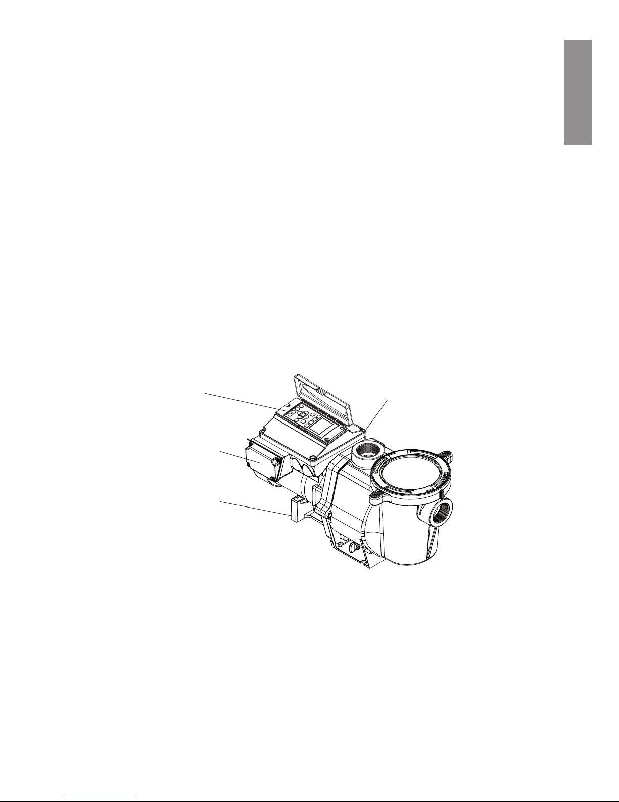
IntelliFlo® VSD Drive Assembly and Control Panel
The IntelliFlo® drive assembly consists of an operator control panel and the system electronics
that drive the motor. The drive microprocessor controls the motor by changing the frequency of
the current it receives together, with changing the voltage to control the rotational speed.
IntelliFlo® VSD Drive Assembly
IntelliFlo® VSD Motor Features
• Permanent Magnet Synchronous Motor (PMSM)
• High efciency (3450© RPM 92% and 1000 RPM 90%)
• Superior speed control
• Operates at lower temperatures due to high efciency
• Same technology as deployed in hybrid electric vehicles
• Designed to withstand outdoor environment
• Totally enclosed fan cooled
• Six-Pole
• Low noise
Motor Stand
Operator Control Panel,
Buttons and LED
AC Power Connection
Compartment
Communication port for connection
to IntelliPool control system or
IntelliComm communication center via
two-wire RS-485 cable.
English
9
Section 2
Operator Control Panel
This section describes the IntelliFlo® Variable Speed pump operator controls and LEDs.
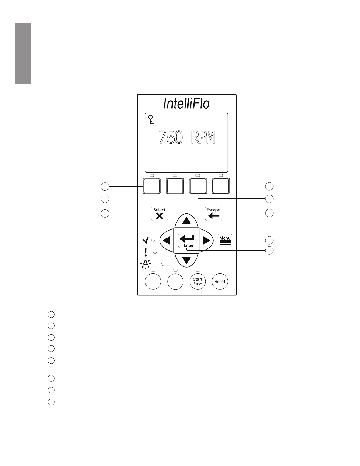
IntelliFlo® VSD Operator Control Panel
Controls and LEDs
Speed 1 button/LED: Press button to select Speed 1 (750 RPM). LED on indicates Speed 1 is active.
Speed 2 button/LED: Press button to select Speed 2 (1500 RPM). LED on indicates Speed 2 is active.
Speed 3 button/LED: Press button to select Speed 3 (2350 RPM). LED on indicates Speed 3 is active.
Speed 4 button/LED: Press button to select Speed 4 (3110 RPM). LED on indicates Speed 4 is active.
Select button: Displays available menu items or enters edit mode for changing a value on line two of the
display.
Escape button: Moves to next level up in the menu structure, and/or stops editing the current setting.
Menu button: Accesses the menu items if the pump is stopped.
Enter button: Saves current menu item setting. Press this button to acknowledge alarms and warning
alerts.
5
1
2
3
4
6
7
8
12:15
750 RPM
T 0.00 150 WATTS
Running Speed 1
1
5
2
6
8
4
3
7
®
Speed
1
Speed
2
Speed
3
Speed
4
Quick
Clean
Time
Out
Current Speed
Current Feature Running
Current Time
Current Power Usage
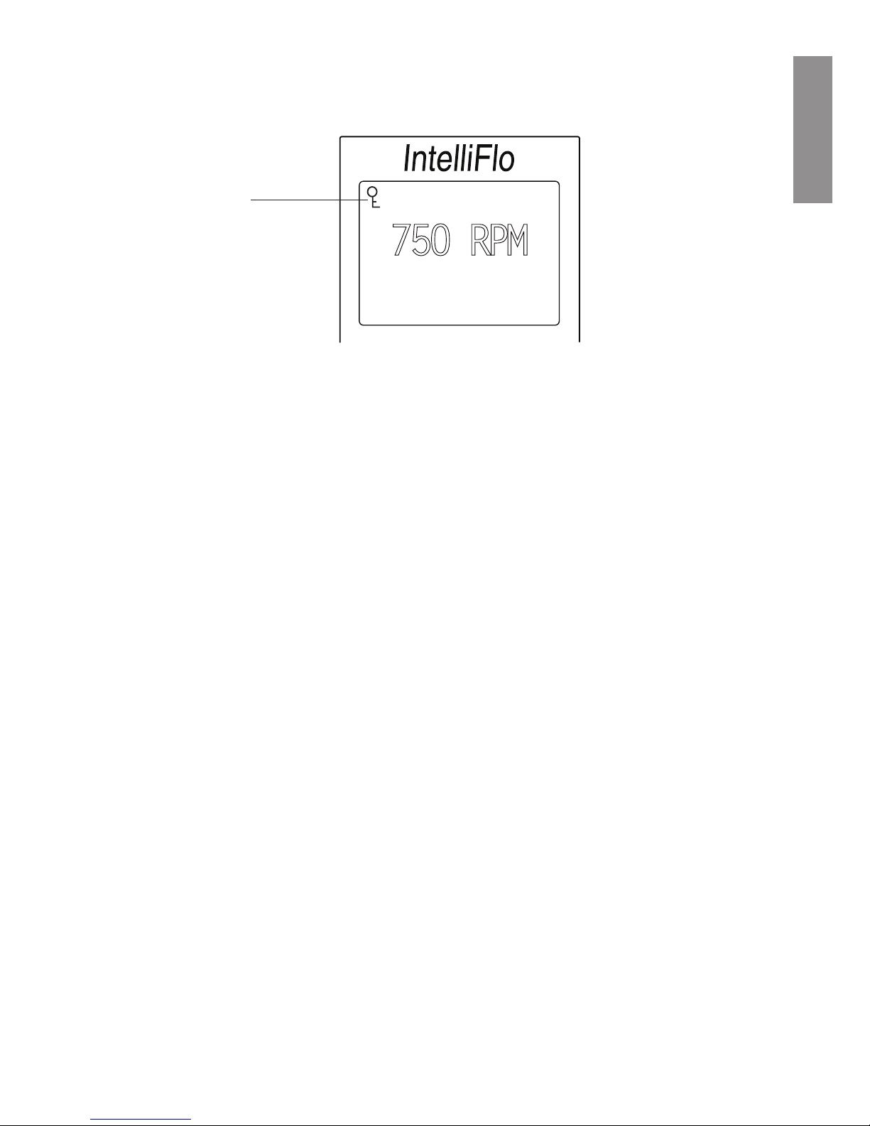
Line 1: Key Lockout Icon
Line 3: Countdown Time
Line 4:
Line 2:
English
10
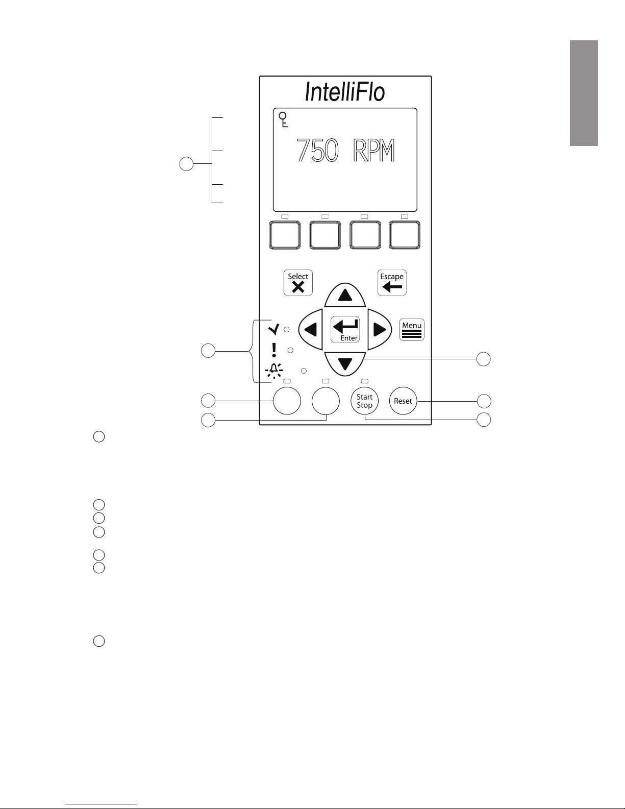
Arrow buttons:
• Up arrow: Move one level up in the menu tree or increase a digit when editing a setting.
• Down arrow: Move one level down in the menu tree or decrease a digit when editing a setting.
• Left arrow: Move cursor left one digit when editing a setting.
• Right arrow: Move cursor right one digit when editing a setting.
Quick Clean: Duration and speed (RPM) can be preset to save energy. The LED is on when active.
Time Out: When active (LED on), at the end of a “Time Out” preset time, the pump will run a schedule.
Start/Stop button: Start or Stop the pump. When the LED is on, the pump is currently running or in a
mode to start automatically.
Reset button: Reset alarm or alert.
LEDs
On: This green, power LED is on when IntelliFlo® is powered on.
Warning: LED is on if a warning condition is present.
Alarm: The red LED is on if an alarm condition occurs. See “Alerts and Warnings” on page 37.
Control Panel LCD:
• Line 1 - Key icon indicates password protect mode is active. If password protect is not enabled, no key
icon is displayed.
• Line 2 - Displays the current pump speed (RPM).
• Line 3 - Count down time and Watts
• Line 4 - Current pump status.
9
10
11
12
13
14
15
12:15
750 RPM
T 0.00 150 WATTS
Running Speed 1
®
Speed
1
Speed 2Speed
3
Speed
4
Quick
Clean
Time
Out
15
Line 1
Line 2
Line 3
Line 4
9
13
12
10
11
14
Controls and LEDs (Continued)
English

11
Section 3
Operating the Pump
This section describes how to operate the IntelliFlo® pump using the control panel buttons and menu
features.
Starting the pump
To start the pump
1. Be sure the pump is powered on and the green power LED is on.
2. Select one of the speed buttons, then press the Start button (LED on) to start the pump.
Stopping the pump
To stop the pump
• Press the Stop button to stop the pump.
Note: The pump can automatically restart if the communication cable is connected.
Servicing Equipment (Disconnect Power to Pump)
• When servicing equipment (lters, heaters, chlorinators etc.), disconnect the
communication cable, and switch OFF circuit breaker to remove power from the pump.
Operating the IntelliFlo Pump at Preset Speeds
The IntelliFlo® VSD pump is programmed with four default speeds of 750, 1500, 2350 and 3110
RPM. A Speed button is assigned to each of the preset speeds as shown.
To operate the pump at one of the four preset speeds
1. Be sure the pump is powered on and the green power LED is on.
2. Press the Speed button (1- 4) corresponding to the desired preset speed, and release
quickly. The LED above the Speed button will come on as shown.
3. Press the Start button. The pump will quickly ramp to the selected preset speed.
Adjusting the pump speed
1. While the pump is running, press the Up Arrow to increase speed setting.
2. Press the Down Arrow to decrease speed Setting.
3. Press and hold down a Speed Button for three (3) seconds to save speed to the button or
press the Enter button to save the speed.
Speed
1
Speed
2
Speed
3
Speed
4
LED lit
English

12
Pump Operating Modes
The IntelliFlo® VSD pump can be programmed three ways:
1. Manual Operation: Speed buttons 1-4 can be programmed for Manual operation. This
means the speed button is pressed and then the start button and the pump runs a programmed
speed. Speeds 5-8 cannot be programmed for Manual operation because there are no buttons
associated with them.
To operate the pump in Manual Mode, press one of the four speed buttons, and press the
Start/Stop button to run the assigned speed for that button. When the pump is running a
Manual Speed Setting (speed 1, 2, 3 or 4 button pressed manually) and a scheduled speed is
set to run, the scheduled speed will take priority regardless of speed (RPM) assigned to each
button. When the Scheduled Speed’s time is over, it will not revert back to the manually
pressed speed. If the pump is running a schedule and a speed button is pressed manually, the
pump will run the manually selected speed until the next scheduled speed program.
2. Egg Timer (Duration): Speeds 1-4 can be programmed to run for a duration of time once
pressed. This means that the Speed button is pressed and then the start button and the pump
runs a programmed speed and the speed will turn off at the end of a preprogrammed amount
of time. Speeds 5-8 have no direct pump speed buttons and therefore cannot be programmed
with an Egg-Timer.
3. Schedule: The speed button can be programmed to turn on and off at a certain time. The
LED above the Start/Stop button must be lit for the pump to run schedules. When a speed is
set to run in Schedule mode it can still be operated manually. When a speed is programmed
to run 23 hours and 59 minutes per day it will not turn off. For example, for the pump to run
24 hours per day, program the pump to start at 8:00 AM and stop at 7:59 AM.
Programming the Pump
When the pump is running at a manual speed and password time out is activated the pump can be turned
off but it cannot be turned back on. Pressing the Start/Stop button places it in the Running Schedule
mode. Therefore, it will only run Speeds that are Scheduled to come on at their scheduled Start Time.
English
13
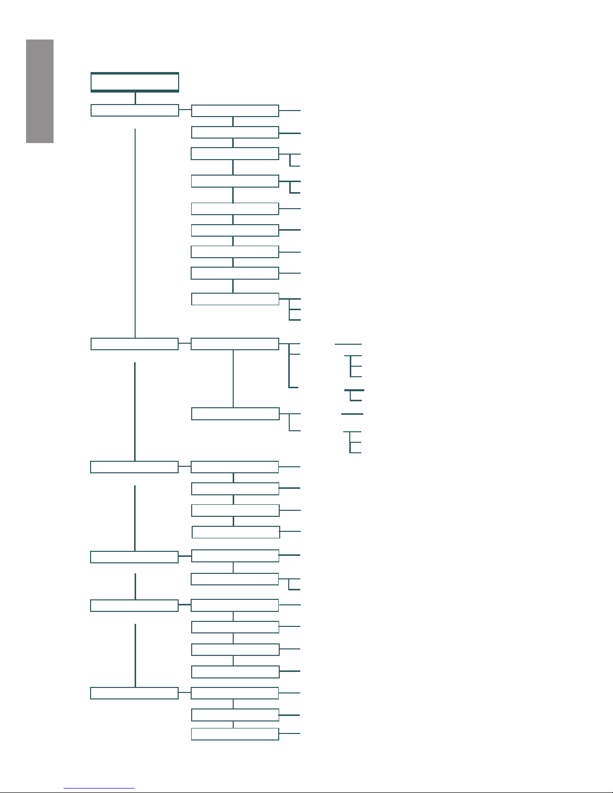
IntelliFlo® VSD Pump Menus
Press MENU button to access menus
MAINSCREEN
(page 14)
SETTINGS
(1-16) Default: ADDRESS 1
(hr:mm) Default: 12:00 AM
Set AM /PM
AM /PM
24 hr.
Fahrenheit - Default: F°
C° Celsius
(1-5) Default 3
(450 RPM - 1700 RPM) - Default: 450 RPM
(1900 RPM - 3450 RPM) - Default: 3450 RPM
Pump Address
Set Time
Tem perature Unit
Screen Contrast
Language
Set Min Speed
Set Max Speed
PASSW ORD
Passw ord Time Out (1 min. - 6 hours) Default:10 minutes
Disabled/Enabled - Default: Disabled
Enter Passw ord (xxxx) Default: 1234
(page 19)
SPEED 1-8
Speed 1 (1-4)
M anual
Schedule
Egg Timer
Set Speed - Default: MANUAL
Set Speed
Set Start Time
Set Stop Time
Set Speed
Time
(page 20)
EXT CONTROL
Program 1
Speed - Default: 750 RPM
Speed - Default: 1500 RPM
Program 2
(page 20)
FEATURES
Quick Clean
Set Speed (1100 -3450 RPM) Default: 3450 RPM
Time (1 min. to 10 hrs.) Default: 10 minutes
Time Out Duration (1 min. to 10 hrs.) Default: 3 hours
Time Out
(page 22)
PRIMING
DISABLED/ENABLED
(1 min. to 30 min. hrs.) Default: 11 minutes
M AX PRIMING TIME
(page 24)
ANTI FREEZE
Disabled / Enabled - Default: Enabled
Program 3
Speed - Default: 2350 RPM
Speed - Default: 3110 RPM
Program 4
English, French, Germ an, Dutch, Spanish, Italian,
Portuguese - Default: English
Speed 5 (5-8)
Schedule
Set Speed
Set Start Time
Set Stop Time
Disabled
Default: Disabled
Default: Enabled
(1 - 100% ) Default: 1
PRIMED SENSITIVITY
(1 second - 10 minutes) Default: 20 seconds
PRIMING DELA Y
DISABLED/ENABLED
SET SPEED
40° F - 50° F (4.4° C - 10° C) Default: 40° F (4.4° C)
PUMP TEM PERATURE
Set Speed (750 RPM - 3450 RPM) Default 1000 RPM
English

14
IntelliFlo® VSD Pump Menus
The IntelliFlo® pump menu descriptions are as follows:
Settings: Pump Address
The “Pump Address” setting is used when the IntelliFlo® pump is connected via the RS-485 COM port
to an IntelliPool or IntelliComm® system. The default pump address is #1. When connected to IntelliPool
or IntelliComm® the pump only communicates with address #1.
Note: IntelliFlo® pumps cannot be connected in series with other pumps.
To access the Settings menu:
1. Be sure the green power LED is on and the pump is stopped.
2. Press the Menu button. “Settings” is displayed.
3. Press the Select button. “Pump Address” is displayed. The Factory default setting is address
“1.”
4. To change the pump address, press the Select button. The rst digit “1” selected.
5. Press Up or Down arrow button to change the address number from 1-16.
6. Press the Enter button to save the setting. To cancel any changes, press the Escape button to
exit edit mode without saving.
7. Press the Escape button to exit.
Settings: Set Time
Use “Set Time” to set the IntelliFlo® system time. The IntelliFlo® system clock controls all scheduled
start and stop times, functions, and programmed cycles. The system clock can store the correct time for
up to 96 hours after power is shut off. The IntelliFlo® will retain the time memory for 96 hours before
a reset is needed.
To access the Set Time menu:
1. Check that the green power LED is on.
2. Press the Menu button. “Settings” is displayed.
3. Press the Select button. “Pump Address” is displayed.
4. Use the Up or Down arrow button to scroll to “Set Time”
5. Press the Select button. The cursor will appear in the Minutes column.
6. Press Up or Down arrow button to set the time.
7. Press the Enter button to save the setting. To cancel any changes, press the Escape button to
exit edit mode without saving.
8. Press the Escape button to exit.
English

15
Settings: Set AM/PM or 24 Clock
This setting is for changing the pump’s time clock from regular time (AM/PM) to a 24 hour
clock. For example, Midnight (12:00 AM) is 0000 hr., 8:00 AM is 0800 hr., and 11:00 PM is
2300 hr.
To access the AM/PM or 24 hr. menu:
1. Check that the green power LED is on.
2. Press the Menu button. “Settings” is displayed.
3. Press the Select button. “Pump Address” is displayed.
4. Use the Up or Down arrow button to scroll to “AM/PM.”
5. Press the Select button to change the setting.
6. Press Up or Down arrow button to choose between 24 hr. and AM/PM.
7. Press the Enter button to save the setting. To cancel any changes, press the Escape button
to exit edit mode without saving.
8. Press the Escape button to exit.
Settings: Set Temperature Unit
Use this setting to set the temperature unit to Celsius (°C), or Fahrenheit (°F). The IntelliFlo®
AntiFreeze protection feature (see page 24) can be set to either Fahrenheit or Celsius.
To access the Temperature Units menu:
1. Check that the green power LED is on.
2. Press the Menu button. “Settings” is displayed.
3. Press the Select button. “Pump Address” is displayed.
4. Use the Up or Down arrow button to scroll to “Temperature Units” menu item. The
factory default setting is “F” (Fahrenheit).
5. Press the Select button. “F” is displayed.
6. Press Up or Down arrow button to choose between Celsius (°C), or Fahrenheit (°F).
7. Press the Enter button to save the setting. To cancel any changes, press the Escape button
to exit edit mode without saving.
8. Press the Escape button to exit.
Settings: Screen Contrast Level
This setting changes the contrast of the LCD screen. The default setting is 3. Screen contrast levels
can be adjusted from 1 to 5 units for low or high lighting conditions.
To access the Temperature Units menu:
1. Check that the green power LED is on.
2. Press the Menu button. “Settings” is displayed.
3. Press the Select button. “Pump Address” is displayed.
4. Use the Up or Down arrow to scroll to “Contrast level.
5. Press the Select button. Screen will show current contrast setting number. The default is
“3”.
6. Press the Select button to change the setting. Number will highlight.
7. Press the Enter button to save the setting. To cancel any changes, press the Escape button
to exit edit mode without saving.
8. Press the Escape button to exit.
English

16
Settings: Language
To access the language menu:
1. Check that the green power LED is on.
2. Press the Menu button. “Settings” is displayed.
3. Press the Select button. “Pump Address” is displayed.
4. Use the Up or Down arrow button to scroll to “Language”.
5. Press the Select button to access the language menu.
6. Press Select to highlight current Language in use.
7. Press the Enter button to select the desired language for the control panel. To cancel any
changes, press the Escape button to exit edit mode without saving.
8. Press the Escape button to exit.
Settings: Set Minimum Speed (RPM)
The minimum pump speed can be set from 450 RPM to 1700 RPM. The default setting is 450 RPM.
To access the Set Minimum Speed menu:
1. Check that the green power LED is on.
2. Press the Menu button. “Settings” is displayed.
3. Press the Select button. “Pump Address” is displayed.
4. Use the Up or Down arrow button to scroll to “Set Min Speed”.
5. Press the Select button to change the setting. The cursor will appear in the rst number
column (ones)
6. Press Up or Down arrow button to change the pump’s minimum speed setting from 450 to
1700 RPM.
7. Press the Enter button to save the setting. To cancel any changes, press the Escape button to
exit edit mode without saving.
8. Press the Escape button to exit.
Settings: Set Maximum Speed (RPM)
The maximum speed can be set from 1900 RPM to 3450 RPM. The default setting is 3450. This setting
is used to set the maximum running speed of the pump. When the pump is set to Priming “Enabled” the
pump will ramp up to and run at the Maximum Speed setting to attain the prime. A Service Professional
must set the Maximum Speed of the pump to not exceed the maximum ow rate of the system on which
it will operate.
CAUTION: The Maximum Flow rate setting should be set so the system never operates at or
above a 0.635 meter vacuum.
To access the Set Maximum Speed menu:
1. Check that the green power LED is on.
2. Press the Menu button. “Settings” is displayed.
3. Press the Select button. “Pump Address” is displayed.
4. Use the Up or Down arrow button to scroll to “Set Max Speed”.
5. Press the Select button to change the setting. The cursor will appear in the rst number
column (ones)
6. Press Up or Down arrow button to change the pump’s maximum speed setting from 1900 to
3450 RPM.
7. Press the Enter button to save the setting. Press the Escape button to exit. To cancel any
changes, press the Escape button to exit edit mode without saving.
English

17
Settings: Password
When the Password feature is enabled, the pump will enter into password protection mode for a
preprogrammed amount of time after the last button is pressed. The entered password is any combination
of four (4) digits.
To access the Password menu:
1. Check that the green power LED is on.
2. Press the Menu button. “Settings” is displayed.
3. Press the Select button. “Pump Address” is displayed.
4. Use the Up or Down arrow button to scroll to “Password”.
5. Press the Select button. The default setting is “Disabled”.
6. Press the Select button to change the setting.
7. Press Up or Down arrow button to change the setting to Enabled”.
8. Press the Enter button to save the setting.
9. Press Down arrow button. “Password Timeout” is displayed.
Factory default time is 10 minutes, this means the pump will go into Password Protection
mode 10 minutes after the last control panel key press.
10. Press Select to change time setting from 1 minute to 6 hours.
11. Press the Enter button to save the setting.
12. Press Down arrow button. “Enter Password” is displayed.
13. Press Select to change the setting.
14. Press Left or Right arrow button to move cursor and press up and down arrow to change
password number to desired setting.
15. Press the Enter button to save the setting. To cancel any changes, press the Escape button to
exit edit mode without saving.
16. Press the Escape button to exit.
Password Protection
Password: The default for this setting is disabled, which means the pump does not have password
protection. When this feature is enabled, for a preset amount of time after the last button is pressed, the
pump display will prompt for the password before allowing access to the control panel and buttons. The
password must be a four (4) numeric digit password. Write down the password and keep in a secure place.
• When the pump is password protected the pump can always be turned off by pressing the
Start/Stop button.
• When running the pump in manual mode it cannot be turned back on with the press of the
Start/Stop button.
• Pressing the Start/Stop button when the pump is off will return it back to the Running
Cycles Mode and will run at the next scheduled run time. If the present time is within the
scheduled run time the pump will run the scheduled speed.
• All functions including programming are disabled in Password Protection Mode.
• If any button other than the Start/Stop button is pressed, the screen reads Enter Password.
• When Password Protection is enabled there is a key icon displayed in the upper left side of
the LCD.
English
18
Entering Password
• When Password Protection is enabled, press any button (besides the speed button) to prompt
the screen to for a password.
• To enter password, use the left and right arrows to move the cursor and the Up and Down
arrow button to scroll through the digit then press the Enter button to conrm.
12:15
750 RPM
Actual Speed
Running Speed 1
®
Key Lockout Icon
English

19
Speed 1-8 (Schedule a Time to Run the Pump)
By setting a start time and a stop time, Speeds 1-8 can be programmed to run a certain speed at a certain
time of day. To run a scheduled pump speed, press the Start button (LED on). The LCD screen will
display “Running Schedules” when it is ready to run a scheduled speed. If the start button is pressed
during a scheduled speed time, the screen will read Running Speed X and will run speed X. (If priming
is enabled, it will prime rst at the maximum RPM setting of the pump before running speed X.)
Note: The IntelliFlo® pump will not run the scheduled speeds until the Start/Stop button is
pressed (LED on) to place the pump in the “Running Schedule” mode.
To set a schedule to run the pump:
1. Check that the green power LED is on.
2. Press the Menu button. “Settings” is displayed.
3. Use the Up or Down arrow button to scroll to “Speed 1-8”.
4. Press the Select button. “Speed 1” is displayed.
5. Use the Up or Down arrow button to choose the speed you wish to program.
6. Press the Select button. Select Manual, Schedule, or Egg Timer for speeds 1-4. “Disabled”
or “Schedule” for speed 5-8 is displayed.
Speeds 1-4 default setting is MANUAL. To create a schedule for speed 1-4 Press Select to
highlight manual.
Speeds 5-8 default setting is DISABLED. To create a schedule for speed 5-8, Press Select to
highlight Disabled.
7. Use the Up or Down arrow button to scroll to “Schedule”.
8. Press the Enter button.
9. Press the Down arrow button. Set speed will be displayed.
10. Press the Select button to change the speed. The rst digit will highlight (ones digit).
11. Use the Up or Down arrow button to change the speed.
12. Press the Enter button to save the setting.
13. Press the Down arrow button. “Set Start Time” is displayed.
14. Press the Select button to change the start time. The cursor will highlight the minute column.
15. Use the Left arrow button to move the cursor to the hour column if desired.
16. Press the Enter button to save the setting.
17. Press Down arrow. “Set Stop Time” is displayed
18. Press the Select button to change the stop time.
19. Press the Enter button to save the setting.
20. Press the Start/Stop button. The LED above the button will light up and the pump will start
if within a scheduled time or “Running Schedule” is displayed.
When the pump is running a scheduled speed or a duration speed (egg timer) the countdown time
(T 00:01) showing the hours and minutes is displayed on the screen.
Note: Speeds 5-8 can be programmed to operate in Schedule mode only. The IntelliFlo®
Variable Speed pump can run eight (8) different speeds at eight (8) programmed start and stop
times per day.
Note: When two speeds are scheduled during the same run time the pump will run the higher
RPM Speed regardless of Speed # in use.
English

20
Programming for Constant Run
When programming a schedule for a Speed, the Speed can not be programmed with the same start
and stop times. However, it will run without stopping if it is programmed with the Start time set
one minute after the stop time. Example: A single speed will run non stop if programmed with a
Start Time of 8:00 AM and a Stop time of 7:59 AM.
External Control
This function is for programming speeds that will run when the IntelliComm power center controller
sends it a command. For example, Terminal 3 and 4 in IntelliComm will correspond to External Control
Program #1. (5 and 6 to Ext Ctrl #2). Use the External Control feature to program the IntelliComm
power center.
To access the Ext. Ctrl. menu:
1. Check that the green power LED is on.
2. Press the Menu button. “Settings” is displayed.
3. Use the Up or Down arrow button to scroll to “Ext. Ctrl.”.
5. Press the Select button. “Program 1” is displayed.
6. Press the Select button. “750 RPM’ is displayed.
7. Press the Select button. The “RPM” number will highlight.
8. Press Up or Down arrow button to change the RPM setting.
9. Press the Enter button to save the setting. Note: To cancel any changes, press the Escape
button to exit without saving.
10. Press the Escape button.
11. Use the Up or Down arrow button to scroll to “Program 2”.
12. Repeat Step 5 through 9 to set Program 2, 3, and 4.12 Programmable Speeds.
Features: Quick Clean
This feature can be used to ramp the pump up to a higher RPM for vacuuming, cleaning, adding
chemicals, after a storm for extra skimming capability. Press the Quick Clean button (LED on)
and then the Start/Stop button (LED on) to start the pump at preset RPM and duration of time.
When the Quick Clean cycle is over it will resume regular schedules, it will be in the “Running
Schedule” mode.
English

21
Quick Clean (Continued)
To access the Quick Clean menu:
1. Check that the green power LED is on.
2. Press the Menu button. “Settings” is displayed.
3. Use the Down arrow button to scroll to “Features”.
5. Press the Select button. “Timeout” is displayed.
6. Press the Down arrow button. “QuickClean” is displayed.
7. Press the Select button. “Set Speed” is displayed.
8. Press the Select button. The “RPM” rst (ones) column will highlight.
9. Use the Up or Down arrow button to change the speed.
10. Press the Enter button to save the setting.
11. Press the Down arrow button. “Time Duration” is displayed.
12. Press the Select button. The cursor will appear in the minutes column.
13. Use the Up or Down arrow button to change the time from 1 minute to 10 hours.
14. Press the Enter button to save the setting. Note: To cancel any changes, press the Escape
button to exit without saving.
15. Press the Escape button to exit.
Features: Time Out
This feature keeps the pump from running for a programmable amount of time. This feature can be
used to allow newly glued pipe joints time to dry before circulation of the pool water is resumed.
This feature keeps the pump from running for a programmable amount of time. When this feature’s
time is up, the pump will be in the “Running Schedule” mode, Start/Stop LED will be lit and ready
to turn on at the next scheduled run time.
To access the Time Out menu:
1. Check that the green power LED is on.
2. Press the Menu button. “Settings” is displayed.
3. Use the Down arrow button to scroll to “Features”.
5. Press the Select button. “Timeout” is displayed.
6. Press the Select button. “Timeout Duration” is displayed.
7. Press the Select button. The “Minutes” column will highlight.
8. Press the Left arrow button to scroll to the hours setting. Time out can be set from 1 minute
to 10 hours.
9. Press the Enter button to save the setting. Note: To cancel any changes, press the Escape
button to exit without saving.
10. Press the Escape button to exit.
English

22
Priming
The default setting for Priming is ENABLED. Enabling this feature allows the pump to use its “Flow
Technology” to be sure the pump is primed for startup. This feature will not override the “Max Speed”
setting. The priming feature ramps the pump to 1800 RPM and pauses for three (3) seconds. If there is
sufcient water ow in the pump basket, the pump will go out of priming mode and run its commanded
speed. If the ow in the pump basket is not sufcient, the pump will ramp to the “Max Speed” setting
and stay there for the priming delay time, which is defaulted at 20 seconds. If there is sufcient water
ow in the pump basket at this time, it will go out of priming mode and ramp to the commanded speed.
If there is still insufcient ow in the pump basket, the pump will try to prime at the “Maximum Speed”
for the amount of time set up in the “Maximum Priming Time” menu.
Maximum Priming Time: The Maximum Priming Time can be set from 1 minute to 30 minutes. The
default setting is 11 minutes. This is the maximum amount of time the pump will try to prime before
giving an error. However if the pump does not see a sufcient amount of water in the pump basket this
can cause the pump to report a Priming Dry Alarm within seconds of the beginning of the priming cycle.
Priming Dry Alarm: An insufcient amount of water in the basket during priming will cause the
pump to report a Priming Dry Alarm. The basket should be lled with water and the pump restarted
when this alarm occurs.
Note: When a Priming Dry Alarm takes place it will try to restart after 10 minutes.
Primed Sensitivity: The primed sensitivity can be set from 1% to 100%. The factory default setting
is 1% meaning that the pump is at its most sensitive setting in regards to determining if the pump has
attained a prime or not. Increasing this number will decrease the amount of ow needed for the pump
to sense that it is primed. Making this number too high could cause the pump to think it has attained
a prime and evacuated the air from the system when it has not. If the system is such, that the pump
has trouble coming out of the priming mode and it is evident that the pump basket is full of water and
owing then the Primed Sensitivity number can be increased.
Priming Delay: The priming delay can be set from 1 second to 10 minutes. The default setting is 20
seconds. This means the pump will ramp to 1800 RPM and stay there for three (3) seconds which it
will always do in the hard Priming Mode. If there is sufcient ow in the pump basket, the pump will
then go out of priming mode and ramp to its commanded speed. If there is insufcient water ow in
the pump basket, the pump will ramp to the Max Speed Setting and stay there for the default time of
20 seconds. It may be necessary to increase the prime delay to allow the system to stabilize before the
pump goes into running mode. If the pump errors out immediately after priming, then increasing the
Priming Delay time may correct the issue.
When the pump is connected to an automation system and the “Maximum Prime Time” feature is
enabled, it will remain active.
Continue to next page for priming MENU information.
English

23
Priming (Continued)
To access the Priming menu:
1. Check that the green power LED is on and press the Menu button. “Settings” is displayed.
2. Use the Down arrow button to scroll to “Priming”.
3. Press the Select button. The factory default is set to priming “Enabled“.
4. To disable priming, press the Select button.
5. Use the Up arrow button. “Disabled” is displayed.
6. Press the Enter button.
7. Press the Down arrow button. Screen will read “Max Priming Time”. The factory default is
set to 11 minutes.
8. Press the Select button to change the setting. The cursor will highlight the minutes column.
9. Use the Up or Down arrow button to change the time from 1 minute to 30 minutes.
10. Press the Enter button to save the setting.
11. Press the Down arrow button. The screen will read “Primed Sensitivity”. The default for
this setting being “1”.
12. Press the Select button to change the setting. The cursor will highlight the number.
13. Use the Up or Down arrow button to change the time from 1% to 100%. Increasing the
number makes the Priming less sensitive.
14. Press Enter to save.
15. Press the Down arrow button. Screen will read “Priming Delay”. The default for this
setting is 20 seconds.
16. Press the Select button to change the Setting.
17. Use the Up or Down arrow button to change the setting from 1 second to 10 minutes.
Caution: Increasing the Priming Delay causes the pump to stay in the priming mode longer.
18. Press the Enter button to save the setting. Note: To cancel a change, press the Escape
button instead of the Enter button to exit without saving.
19. Press the Escape button to exit.
Disable Priming Feature on the Pump
When the IntelliFlo® VSD pump is connected to an automation control system, the priming feature
on the pump cannot be disabled by the external automation control system only. If the IntelliFlo®
pump is connected to an automation control system and priming is not desired, disable the priming
feature on the pump.
To disable priming with an automation control system:
1. Temporarily disconnect the RS-485 communication cable.
2. Open the LCD screen lid to disable priming on the pump. Press the MENU button, use the
arrow buttons to scroll and select “Priming”, then select “Disabled” (the factory default is
set to “Enabled”). Press Escape to exit the menu.
3. Once priming is disabled, reinstall the RS-485 communication cable.
English

24
AntiFreeze
This feature allows you to set a speed (450 RPM -3450 RPM) that will run when the pump goes into
anti freeze mode. The temperature level that you wish anti freeze mode to start can also be set.
IMPORTANT NOTE: This feature is for protection of the pump. Do not depend on the antifreeze feature
for freeze protection of the pool. Certain situations could cause the pump to sense a different temperature
than actual air temperature. Your automation systems air temperature sensor should be used to sense
actual temperature. For example, if the pump is located indoors, the temperature of the room does not
indicate the outdoor temperature. The pump does not sense the water temperature.
To access the AntiFreeze menu:
1. Check that the green power LED is on.
2. Press the Menu button. “Settings” is displayed.
3. Use the Down arrow button to scroll to “AntiFreeze”.
4. Press the Select button. The factory default is AntiFreeze “Enabled“.
5. To disable AntiFreeze. Press the Select button, “Enabled” will highlight.
6. Use the Up arrow button. “Disabled” is displayed.
7. Press the Enter button.
To program AntiFreeze when enabled:
8. Press the Down arrow button.“Set Speed” is displayed. The factory default is 1000 RPM.
9. Press the Select button to change the setting. The cursor will highlight the rst column
(ones).
10. Use the Up or Down arrow button to select 450 - 3450 RPM.
11. Press the Enter button to save the setting.
12. Press the Down arrow button. “Pump Temperature” is displayed. This is the temperature the
pump will activate AntiFreeze. The factory default is 40° F (4.4° C).
13. Press the Select button to change the setting. The cursor will highlight the rst column
(ones). This setting can be changed from 40° F to 50° F (4.4° C - 10° C).
14. Press the Enter button to save the setting. Note: To cancel any changes, press the Escape
button to exit without saving.
15. Press the Escape button to exit.
English
25
Priming the pump for the rst time, or after service
The IntelliFlo® must be primed before starting the pump for the rst time. To prime a pump
means lling the pump and suction pipe with water. This process evacuates the air from all the
suction lines and the pump. It may take several minutes to prime depending on the depth of
water, pipe size and length. It is easier to prime a pump if you allow all the air to escape from the
pump and pipes. The water cannot enter unless the air can escape. Pumps do not hold prime, the
pool piping system has that task.
CAUTION - To avoid permanent damage to the IntelliFlo
®
pump, before starting the pump, ll the IntelliFlo®
housing strainer with water so that the pump will prime correctly. If there is no water in the strainer
the pump will not prime.
• Do not allow the pump to run dry. Running the pump dry may damage the seals, causing leakage
and ooding.
• Do not add chemicals to the system directly in front of pump suction. Adding undiluted chemicals
may damage the pump and will void the warranty.
• Open gate valves before starting system.
• Be sure to release all air from lter and piping system.
• The IntelliFlo® pump is a variable speed pump. Typically the lower speeds are used for ltration
and heating. The higher speeds can be used for spa jets, water features, and priming.
CAUTION - Before starting this procedure, rst read the following:
Before removing the pump lid:
1. Press the Stop button if the pump is running before proceeding.
2. Disconnect the communication cable from the pump.
3. Disconnect main power supply
4. Close the gate valves in suction and discharge pipes.
5. Release all pressure from pump and piping system.
6. Never tighten or loosen the locking ring while the pump is operating.
WARNING -
WARNING -
If the pump is being pressure tested, release all pressure before removing trap cover. Do not block the
pump suction while the pump is running. If a body part blocks the pump suction it may cause severe or
fatal injury. Small children using the pool must ALWAYS have close adult supervision.
FIRE and BURN HAZARD - The pump motor may run at a high temperatures. To reduce
the risk of re, do not allow leaves, debris, or foreign matter to collect around the pump motor. To
avoid burns when handling the motor, shut off the motor and allow it to cool for 20 minutes before
trying to work on it. The IntelliFlo® provides an automatic internal cutoff switch to protect the motor
from heat damage during operation.
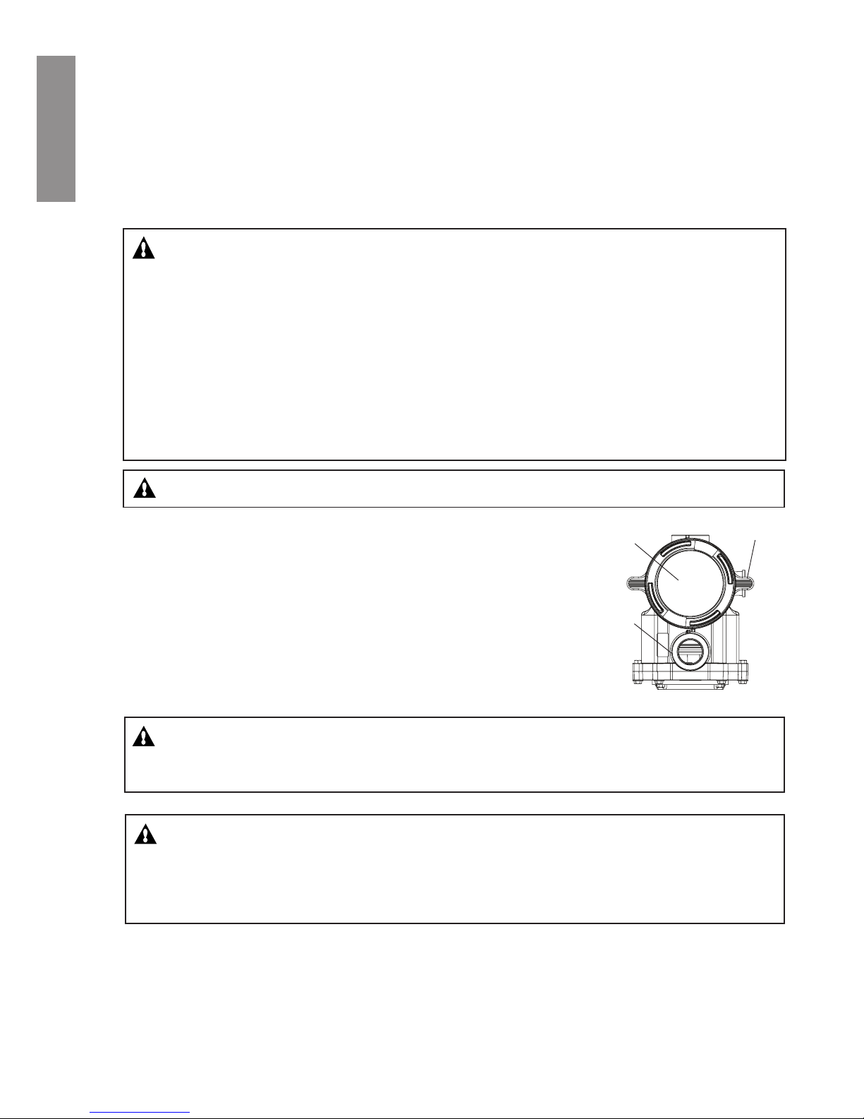
Top view
Lid
Locking
ring
Volute
English

26
Priming the pump for the rst time, or after service (Continued)
Priming the Pump
NOTICE: If you replace the o-ring with a non-lubricated o-ring, you may need to apply a silicone
based lubricant.
• Clean and inspect o-ring; reinstall on trap cover.
• Replace trap cover on trap; turn clockwise to tighten cover.
NOTICE: Tighten the pump lid by hand only (no wrenches).
Priming time will depend on vertical length of suction lift and horizontal length of suction piping.
If pump does not prime, be sure that all valves are open, suction pipe end is under water, pump
suction is below water level, and that there are no leaks in suction pipe.
To prime the IntelliFlo® pump:
1. Turn the locking ring in a counter-clockwise direction until it stops and remove them.
2. Fill the pump strainer pot with water.
3. Check the system and ensure water has an open path for free system ow.
4. Reinstall the locking ring and lid onto the strainer pot. The pump is now ready to prime.
5. Be sure all electrical connections are clean and tight.
6. Open the air release valve on the lter, and stand clear of the lter.
7. Switch the pump on at the circuit breaker. Ensure that the green power light is on.
8. Press the Speed 1 button to select the pump speed of 750 RPM.
9. Press the Start button to start the pump. Use the Up/Down button to increase the speed as
necessary to prime the pump.
10. When water comes out of the air release valve, close the valve. The system should now be
circulating water back to the pool without air bubbles showing in either the hair and lint pot or at
the pool return ttings.
11. Use the Up/Down button to adjust the operating speed as desired.
Top view
Lid
Locking
ring
Volute
English
27
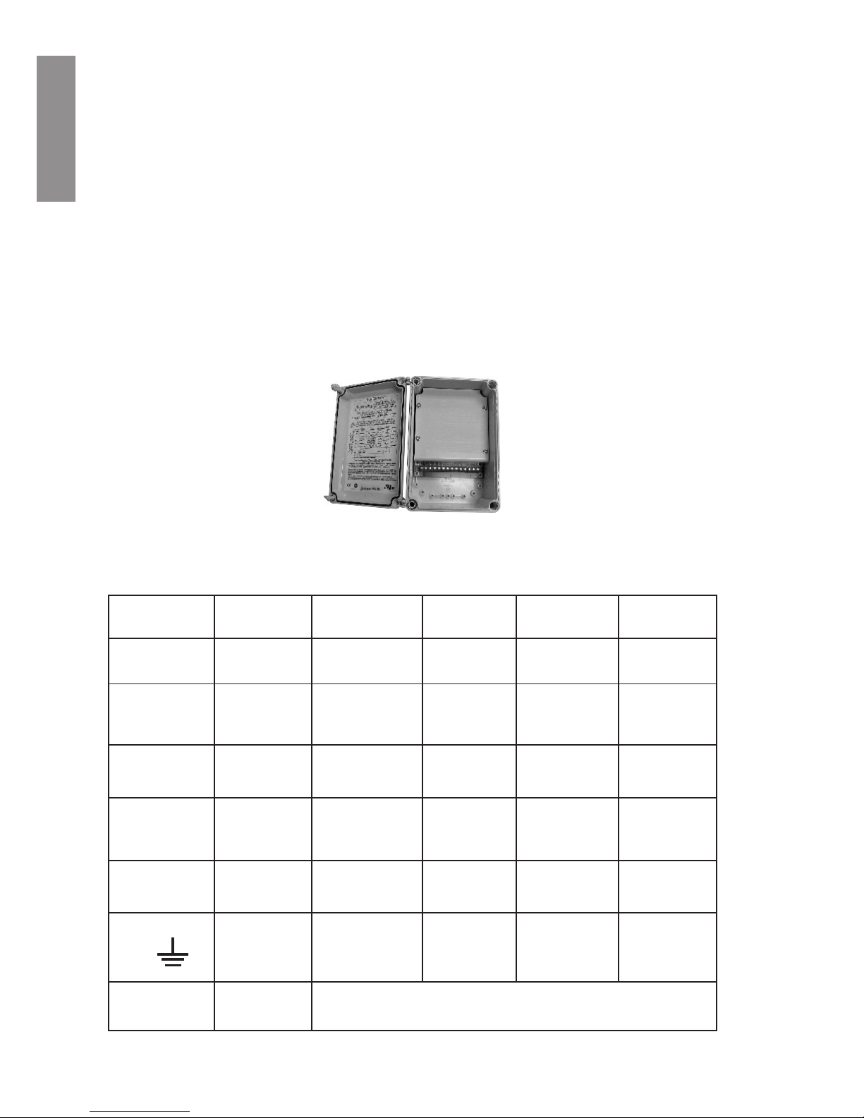
External Control with IntelliComm® Communication Center
The IntelliFlo® pump can be remotely controlled by the Pentair IntelliComm Communication
Center using the RS-485 communications cable. The IntelliComm provides four pairs of input
terminal connections. These inputs are actuated by either 15 - 240 VAC or 15 - 100 VDC. Using
the device’s inputs, the programmed IntelliFlo® pump speeds can be controlled.
Note: For the IntelliFlo® pump to accept commands from IntelliComm, the pump must be
in the “Running Schedules” mode (LED above the Start/Stop button lit).
If more than one input is active the highest number will be communicated to the IntelliFlo®
pump. The IntelliComm will always communicate to pump using ADDRESS #1.
Program number priority is as follows: Example: If programs 1 and 2 are activated, program
2 will run, regardless of the assigned speed (RPM). The higher program number (2 being
higher) will always take priority. The following table shows the wiring terminal descriptions for
IntelliComm.
External Control
IntelliComm Communication Center
Terminal
Number
Terminal Name Voltage
Maximum
Current
Phase Type Frequency
1-2 Power Supply 100 - 240 VAC 100 mA 1 Input 50/60 Hz
3-4 Program 1
15 -240 VAC
or
15 - 100 VDC
1 mA 1 Input 50/60 Hz
5-6 Program 2
15 -240 VAC
or
15 - 100 VDC
1 mA 1 Input 50/60 Hz
7-8
Program 3
15 -240 VAC
or
15 - 100 VDC
1 mA 1 Input 50/60 Hz
9-10 Program 4
15 -240 VAC
or
15 - 100 VDC
1 mA 1 Input 50/60 Hz
11
12
RS-485
+ Data: Yellow
- Data: Green
-5 to +5 VDC 5 mA 1 Output N/A
Ground
English

28
Connecting the IntelliFlo® pump to a IntelliPool System
The IntelliFlo® pump can be controlled by an IntelliPool system via the RS-485 communication
cable.
WARNING - Switch OFF main system power to the IntelliPool Control Center before making any
connections.
To connect the IntelliFlo® pump RS-485 communication cable to the IntelliPool circuit board:
1. Open the front of the IntelliPool control center.
2. Remove the red protective panel
3. Route the two conductor cable up through the control center grommet opening located on the
right side, and up through the bus connector to the motherboard.
4. Strip back the cable conductors 6 mm (1/4”). Insert the wires into the screw terminals. Secure
the wires with the screws. Be sure to match the color coding of the wires; YELLOW to COM
– and GREEN to COM + .
5. Close the control center.
12/07 /1 0 1 5:23:48
Temp. eau: +24.0°C
pH:7, 3 RedO x:629m V
Cond: 55 71uS 3.51g/ l
12345678
English
 Loading...