

Pentair INTELLIFLO VSD2, INTELLIFLO SW5P6R-VSD2, INTELLIFLO UFL-VSD2, INTELLIFLO VSF Operating Manual
INTELLIFLO® VSD2
VARIABLE SPEED PUMP
IMPORTANT SAFETY INSTRUCTIONS. READ, FOLLOW AND SAVE THESE INSTRUCTIONS
P-INSB-VSD2 (REV. NOVEMBER 2017)
OPERATING MANUAL
SW5P6R-VSD2
UFL-VSD2
AQUATIC SYSTEMS
We would like to thank you for buying our IntelliFlo® VSD2 pump.
We are convinced that this Pentair pump will be a reliable, userfriendly and cost-efficient
product for keeping your pool running. The variable speed technology of this pump allows
you to run your pump at low speeds. This reduces dramatically the energy consumption of
your pool.
TECHNICAL FICHE
In case you would need technical information, please have a look at the product’s app or at
our website www.pentairpooleurope.eu. By scanning below QR code you will be immediatly
directed to our Pentair website.
INTRODUCTION
CUSTOMER SERVICE
If you have questions about ordering Pentair Aquatic Systems replacement parts and pool
products, please contact:
Customer Service Pisa, Italy (8.30 AM to 4.30 PM CET)
Phone number: +39 050 71 61 66 or +39 050 71 61 69
E-mail: orders.pooleu@pentair.com or poolemea@pentair.com
Website: www.pentairpooleurope.com
Please note that the full manual is available at our website.
GAIN TECHNICAL EXPERTISE WITH TRAINING FROM PENTAIR!
Learn about the latest developments in automation systems, pumps, heaters,
lighting, filtration, water features and chlorine generation. Our experienced
instructors, detailed course materials and training aids will give you the realworld techniques and understanding to specify, install, troubleshoot and service
today’s most advanced pool equipment... profitably. You’ll certainly end up with
a wealth of know-how.
More info: techsupport.poolemea@pentair.com
ACADEMY TRAINING TOUR
!
© 2017 Pentair. All rights reserved.
The manufacturer, Pentair, has the right to change products without notice as far as their
properties do not substantially change. This document is subject to change without notice.
Trademarks and disclaimers: IntelliFlo® and Pentair are trademarks and/or registered
trademarks of Pentair and/or its affiliated companies. Unless noted, names and brands of
others that may be used in this document are not used to indicate an affiliation or endorsement
between the proprietors of these names and brands and Pentair. Those names and brands may
be the trademarks of those parties or others.
ACADEMY

CONTENT
PRESENTATION
> Warnings and Safety Instructions p 04
PUMP OVERVIEW
> Introduction p 07
> External control p 07
> Features p 08
> Drive assembly and control panel p 09
> Motor features p 09
OPERATOR CONTROL PANEL
> Using the operator control panel p 10
> Controls and leds on keypad p 10
OPERATING THE PUMP
> Starting the pump p 12
> Stopping the pump p 12
> Operating the pump at preset speeds p 12
> Pump operating modes p 13
> IntelliFlo VSD2 pump menus p 14
> Programs 1-8 (Schedule a time to run the pump) p 19
> External control p 22
> Time Out Feature p 23
> Quick Clean Feature p 23
> Priming p 24
USER MAINTENANCE
> Pump strainer basket p 32
> Motor service p 33
> Winterizing p 34
> Priming the pump after service p 34
INSTALLATION AND REMOVAL
> Installing the pump p 35
> Pump disassembly p 37
> Shaft seal replacement p 38
> Pump reassembly / seal replacement p 38
> Drive assembly removal and installation p 39
TROUBLESHOOTING
> Alerts and warnings p 40
> General troubleshooting problems p 41
> Thermal mode p 29
> Connecting to an IntelliPool system p 31
3

WARNINGS AND SAFETY INSTRUCTIONS 1/3
This guide mentions the installation- and user guidelines for the IntelliFlo® VSD2. Contact
Pentair if you have any questions regarding this product.
Attention installer: This manual contains important information about the installation,
operation and safe use of this product. This information should be given to the owner and/
or operator of this equipment after installation or left near the pump.
Attention user: This manual contains important information that will help you in operating
and maintaining this product. Please retain it for future reference.
Warnings and safety instructions for Pentair Aquatic System pumps and other related
products are available at our website: www.pentairpooleurope.com
WARNING - ENTRAPMENT AVOIDANCE NOTICE
The suction outlet connected to a swimming pool or spa pump can pull a high vacuum if it
is blocked. Therefore, if only one suction outlet smaller than 46 cm x 58 cm is used, anyone
blocking the suction outlet with their body can be trapped and held against the suction outlet.
An abdominal wound or drowning can result. Therefore, if small suction outlets are used
with this pump, to prevent this entrapment and possible death, install at least two suction
outlets in the body of water. Separate these suction outlets as described in the International
Residential Code (IRC), the International Business Code (IBC), the Consumer Products Safety
Council (CPSC) Guidelines for Entrapment Hazards: Making Pools and Spas Safer or ANSI/
IAF-7 Standard for Suction Entrapment Avoidance in Swimming Pools, Wading Pools, Spas,
Hot Tubs and Catch Basins. If suction outlets are not used, additional entrapment avoidance
measures as described in the CPSC Guidelines or ANSI/IAF-7 should be employed.
The covers used on suction outlets should be approved and listed as conforming to the
currently published edition of ANSI/ASME A112.19.8 Standard covering Suction Fittings for
Use in Swimming Pools, Wading Pools, Spas and Hot Tubs. These covers should be inspected
regularly and replaced if cracked, broken or older than the design lifetime indicated on them
by the manufacturer. The maximum possible flow rate of this pump should be less than
or equal to the maximum approved flow rate indicated on the suction outlet cover by the
manufacturer. THE USE OF UNAPPROVED COVERS OR ALLOWING USE OF THE POOL OR
SPA WHEN COVERS ARE CRACKED OR BROKEN CAN RESULT IN HAIR ENTANGLEMENT
WHICH CAN RESULT IN DEATH.
WARNING - RISK OF ELECTRICAL SHOCK OR ELECTROCUTION
This pool pump must be installed by a licensed or certified electrician or a qualified pool
serviceman in accordance with all applicable local codes and ordinances. Improper installation
will create an electrical hazard which could result in death or serious injury to pool users,
installers, or others due to electrical shock, and may also cause damage to property.
Always disconnect power to the pool pump at the circuit breaker before servicing the pump.
Failure to do so could result in death or serious injury to serviceman, pool users or others
due to electric shock
4
!
!
!
!

WARNINGS AND SAFETY INSTRUCTIONS 2/3
Water temperature in excess of 38° C (100° F) may be hazardous to your health. Prolonged
immersion in hot water may induce hyperthermia. Hyperthermia occurs when the internal
temperature of the body reaches a level several degrees above normal body temperature
of 37° C (98.6° F). The symptoms of hyperthermia include: drowsiness, lethargy, dizziness,
fainting, and an increase in the internal temperature of the body.
The effects of hyperthermia include:
1. Unawareness of impending danger.
2. Failure to perceive heat.
3. Failure to recognize the need to leave the spa.
4. Physical inability to exit the spa.
5. Fetal damage in pregnant women.
6. Unconsciousness resulting in danger of drowning.
WARNING - WATER TEMPERATURE
OTHER WARNINGS
• The use of alcohol, drugs, or medication can greatly increase the risk of gatal hyperthermia
in hot tubs and spas.
• To reduce the risk of injury, do not permit children to use this product.
• For units intended for use in other than single-family dwellings, a clearly labeled
emergency switch shall be provided as part of the installation. The switch shall be readily
accessible to the occupants and shall be installed at least 1.52m (5 feet) away, adjacent
to, and within sight of the unit.
• When setting up flow rates, the operator must consider local codes governing turnover as
well as disinfectant feed ratios.
• Before servicing the system, switch the main power OFF and remove the communication
cable from the pump.
• Install the pump a minimum of 1.5m (5 feet) from the inside wall of the pool and spa.
• This pump is for use with permanently installed pools and may also be used with hot tubs
and spas if so marked. Do not use with storable pools. A permanently installed pool is
constructed in or on the ground or in a building such that it cannot be readily disassembled
for storage. A storable pool is constructed so that it may be readily disassembled for
storage and reassembled to its original integrity and has a maximum dimension of 5.49m
(18 feet) and a maximum wall height of 1.07m (42 inches).
• For hot tubs and spa pumps, do not install within an outer enclosure or benaeth the skirt
of a hot tub or spa unless so marked.
• IntelliFlo® VSD2 is capable of generating system pressures up to 30 meters. Installers
must ensure that all system components are rated to withstand at least 30 meters. Over
pressurizing the system can result in catastrophic component failure or property damage.
5
!
!

WARNINGS AND SAFETY INSTRUCTIONS 3/3
GENERAL WARNINGS
• Never open the inside or the motor enclosure. There is a capacitor bank that holds a 230
VAC charge even when there is no power to the unit.
• The IntelliFlo® VSD2 pump is not submersible.
• The IntelliFlo® VSD2 pump is capable of 35 m3/hr or 30 meters of head. Use caution
when installing and programming to limit pumps performance potential with old or
questionable equipment.
• Code requirements for the electrical connection differ from country to country. Install
equipment in accordance with all applicable local codes and ordinances.
• Always press the stopp button and disconnect the communication cable before performing
maintenance.
• Sufficient equipotential bonding (min. 4.5mm² recommended), in accordance with local
regulations, is required on all metal components of the pool including the pool pump. It
is required for electrical safety as well as to reduce the risk of corrosion.
GENERAL INSTALLATION INFORMATION
• Pumps improperly sized or installed or used in applications other than for which the
pump was intended can result in severe personal injury or death. These risks may include
but not be limited to electric shock, fire ,flooding, suction entrapment or severe injury or
property damage caused by a structural failure of the pump or other system components.
• The pump can produce high levels of suction within the suction side of the
plumbing system. These high levels of suction can pose a risk if a person comes
within the close proximity of the suction openings. A person can be seriously
injured by this high level of vacuum or may become trapped and drown. It is
absolutely critical that the suction plumbing be installed in accordance with the
latest national and local codes for swimming pools.
• In a domestic environment, this product may cause radio interference in which case
supplementary mitigation measures may be required.
• Do not install on IT (insulated terra) mains network (marine applications).
• Fitting a non-return valve after the pump on installation will prevent the impeller from
unwinding and is strongly recommended.
NOTE — If required by local building codes, the pump is to be supplied by an isolating
transformer or supplied through a residual current device (RCD) having a residual operating
current not exceeding 30 mA.
NOTE — Use RCD/GFCI type A or B.
• These instructions contain information for a variety of pump models and therefore
some instructions may not apply to a specific model. All models are intended for use in
swimming pool applications. The pump will function correctly only if it is properly sized to
the specific application and properly installed.
6
!

PUMP OVERVIEW 1/3
The IntelliFlo® VSD2 pump is well suited for all of your pool, spa, cleaner, waterfall and other
water applications. Using the control panel, IntelliFlo® can use one of the four selectable
preset speeds or the pump speed can be adjusted to run at a specific speed. Advanced energy
conservation features ensure that your filtration system is operating at peak efficiency.
The IntelliFlo® pump is a variable speed pump that can use up to eight speeds that can be
adjusted to run at specific speeds and time intervals. The IntelliFlo® VSD2 pump outperforms
all conventional pumps in its class.
The pump can operate from 450 RPM to 3450 RPM with preset speeds of 750, 1500, 2350 and
3110 RPM. The pump can be adjusted from the control panel to run at any speed between 450
RPM to 3450 RPM for different applications. The pump control panel alarm LED and error
messages warn the user against under and over voltage, high temperature, over current and
freeze protection with user defined minimum and maximum speed presets.
The control panel can be mounted on the pump in four different directions in order to provide
the user the best access. The control panel can also be mounted in a more convenient
location with the help of the keypad relocation kit (to be sold separatly: P/N R356905).
INTRODUCTION
EXTERNAL CONTROL
The IntelliFlo® VSD2 pump can communicate with an IntelliPool control system or the
IntelliComm® communication center via a two-wire RS-485 communication cable. The
communication cable is included with the control system. IntelliComm® can remotely control
the IntelliFlo® variable speed four preset speeds. The IntelliPool system can be configured to
control speed in function of pool temperature, size and active features.
7

PUMP OVERVIEW 2/3
• Adjusts to various pool sizes
• Prevents thermal overload
• Detects and prevents damage from under and over voltage conditions
• Protects against freezing
• Communicates with IntelliPool control system or an IntelliComm communication center
• Easy to use operator control panel
• Operator control panel buttons for speed control
• Built-in strainer pot and volute
• Ultra energy-efficient TEFC Square Flange Motor
• Compatible with most cleaning systems, filters, and jet action spas
• Motor assembly features permanent magnet synchronous motor
• Heavy-duty, durable construction designed for long life
• 12 Programmable Speeds
• Speed 1-4: manual, egg timer or schedule
• Speed 5-8: schedule
• Four IntelliComm speed modes
• Priming Feature
• Load Sensing
• Enable or Disable
• Lockout Protection
• Four Digit password
• Enable or Disable
• LCD Display
• Power and Speed / Flow
• Text Alerts
• Antifreeze Protection
• Adjustable Speed / Flow
• Adjustable Temperatures
• Enable and Disable in stand alone
• Additional Features
• Clock and Timer
• Maximum and Minimum Speed / Flow Limits
• Quick Clean Mode
• Timeout Mode
• Rotatable Keypad
FEATURES
8
PUMP OVERVIEW 3/3
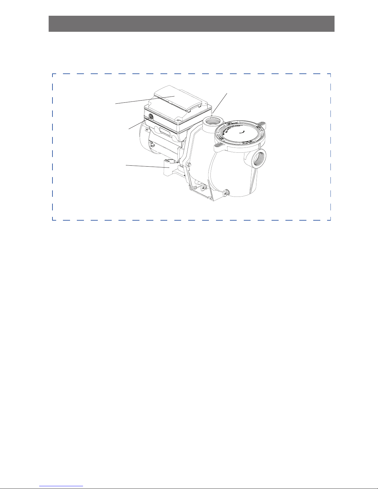
DRIVE ASSEMBLY AND CONTROL PANEL
The IntelliFlo® drive assembly consists of an operator control panel and the system electronics
that drive the motor. The drive microprocessor controls the motor by changing the frequency
of the current it receives, together with changing the voltage to control the rotational speed.
MOTOR FEATURES
• Permanent Magnet Synchronous Motor (PMSM)
• High efficiency (3450 RPM 92% and 1000 RPM 90%)
• Superior speed control
• Operates at lower temperatures due to high efficiency
• Same technology as deployed in hybrid electric vehicles
• Designed to withstand outdoor environment
• Totally enclosed fan cooled
• 10-Pole
• Low noise
9
IntelliFlo® VSD2 Drive Assembly
Motor Stand
Operator Control Panel,
Buttons and LED
Strain Relief Port
for Incoming AC Power
Communication port for connection to
IntelliPool control system or IntelliComm
communication center via two-wire RS-
485 cable.
OPERATOR CONTROL PANEL 1/2
USING THE OPERATOR CONTROL PANEL
Use the operator control panel to start and stop the IntelliFlo® VSD2 Variable Speed Pump,
set, and change speeds (RPM), and access pump features and settings.
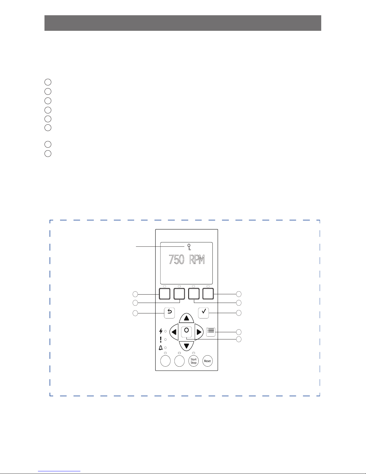
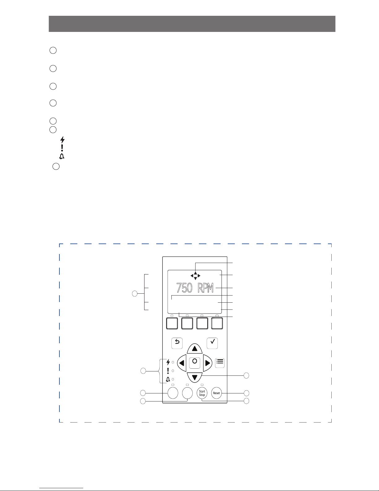
CONTROLS AND LEDS ON KEYPAD
Button 1: Press to select Speed 1 (750 RPM). LED on indicates Speed 1 is active.
Button 2: Press to select Speed 2 (1500 RPM). LED on indicates Speed 2 is active.
Button 3: Press to select Speed 3 (2350 RPM). LED on indicates Speed 3 is active.
Button 4: Press to select Speed 4 (3110 RPM). LED on indicates Speed 4 is active.
Back: Goes one step back in menu; exits without saving current setting.
Save: Saves current menu item setting. When a parameter has been adjusted the “Save?”
icon will be displayed.
Menu: Accesses the menu items when and if the pump is stopped.
Select: Press to select the currently displayed option on the screen.
Control Panel # 1-8
Note: Always close the keypad cover after using the keypad.
Note: Using screwdrivers or pens to program the pump will damage the keypad overlay. Use
your fingers only when programming the pump.
10
12:15p
750 RPM
T 0.00 150 WATTS
Running Speed 1
SaveBack
Select
Menu
1
5
2
6
8
4
3
7
1 2 3 4
Quick
Clean
Time
Out
1
2
3
4
5
6
7
8
Key Lockout Icon
OPERATOR CONTROL PANEL 2/2
CONTROLS AND LEDS ON KEYPAD - CONTINUED
Arrow Buttons: Move to different menu levels and increase or decrease digits (up + down)
Move cursor left or right one digit when editing a setting. (left + right)
Quick Clean: Pump increases to a higher RPM (for vacuuming, cleaning, adding chemicals,
etc.). LED light is on when active.
Time Out: Allow the pump to remain in a stopped state for a set period of time before
resuming normal operation. LED is on when active.
Start/Stop button: To start or stop the pump. When LED is on, the pump is running or in
a mode to start automatically.
Reset button: Reset alarm or alert.
LEDs:
On: Green light when pump is powered on.
Warning: On if warning condition is present.
Alarm: Red LED on if alarm condition occurs.
Control Panel LCD Screen:
• Line 1: Key icon indicates password protection mode is active. If password protect is
not enabled, no key icon is displayed. Also shows current time of day. Active cursors
display when arrow key input is available.
• Line 2: Displays current pump speed (RPM).
• Line 3: Countdown time and watts
• Line 4: Current pump status and current feature. “Save?” will display on this line when
a parameter adjustment can be saved.
Control Panel # 9-15
Active Cursors
Current Time
Current Speed
Countdown Time
Current Power Usage
“Save?” Icon
Current Running Feature
11
9
10
11
12
13
14
12:15p
750 RPM
T 0.00 150 WATTS
Running Speed 1
SaveBack
Select
Menu
1
5
2
6
8
4
3
7
1 2 3
4
Quick
Clean
Time
Out
12:15p
750 RPM
T 0.00 150 WATTS
Running Speed 1
SaveBack
Select
Menu
1 2 3
4
Quick
Clean
Time
Out
15
Line 1
Line 2
Line 3
Line 4
9
13
12
10
11
14
Save?
15

OPERATING THE PUMP 1/20
STARTING THE PUMP
To start the pump:
1. Be sure the pump is powered ON and the green power LED is on.
2. Select one of the speed buttons, then press the Start/Stop button (LED on) to start the
pump. The pump will go into priming mode if priming feature is enabled.
This section describes how to operate the IntelliFlo® VSD2 pump using the control panel
buttons and menu features.
STOPPING THE PUMP
To stop the pump:
• Press the Start/Stop button to stop the pump.
Note: The pump can automatically restart if the communication cable is connected.
• When servicing equipment (filters, heaters, chlorinators, etc.), disconnect the
communication cable, and switch OFF circuit breaker to remove power from the pump.
OPERATING THE PUMP AT PRESET SPEEDS
The IntelliFlo® VSD2 pump is programmed with four default speeds of 750, 1500, 2350, 3110
RPM. Speed buttons 1-4 are for each of the preset speeds as shown below.
To operate the pump at one of the four preset speeds:
1. Be sure the pump is powered ON and the green LED is on.
2. Press the Speed button (1-4) corresponding to the desired preset speed, and release
quickly. The LED above the button will turn on as shown.
3. Press the Start/Stop button. The pump will quickly change to the selected preset speed.
Adjusting the pump speed:
1. While the pump is running, press the Up or Down Arrow to adjust to desired speed setting.
2. Press and hold down a Speed Button for three (3) seconds to save speed to the button or
press Save to save the speed.
12
LED lit
1 2 3
4
OPERATING THE PUMP 2/20
PUMP OPERATING MODES
The IntelliFlo® VSD2 Pump can be programmed in three different modes:
• Speeds 1-4 can be programmed in all three modes.
• Speeds 5-8 can only be programmed in Schedule mode since there are no buttons on the
control panel for Speeds 5-8. The default setting for Speeds 5-8 is “Disabled”.
Manual
Assigns a speed to one of the four speed buttons on the control panel. This mode can only be
used for speeds 1-4. Speeds 1 and 2 are Manual by default.
To operate in manual mode, press one of the four speed buttons and then press the Start/
Stop button. The pump will run the assigned speed assigned to that speed button.
Egg Timer
Speeds 1-4 can be programmed to run at a certain speed and for a duration of time once a
program button is pressed.
Programs 3 and 4 are Egg Timers by default. If you desire a different method of operation,
programs 3 and 4 can be changed to Manual mode in the control menu.
To operate in Egg Timer mode, press a speed button and then press Start/Stop. The pump
will run that setting for the set amount of time and then turn off.
Schedule
Program speeds 1-8 start and stop at a specific time during a 24 hour period. Speeds
programmed in Schedule mode will override any manually selected speed once the next
Schedule command commences.
13
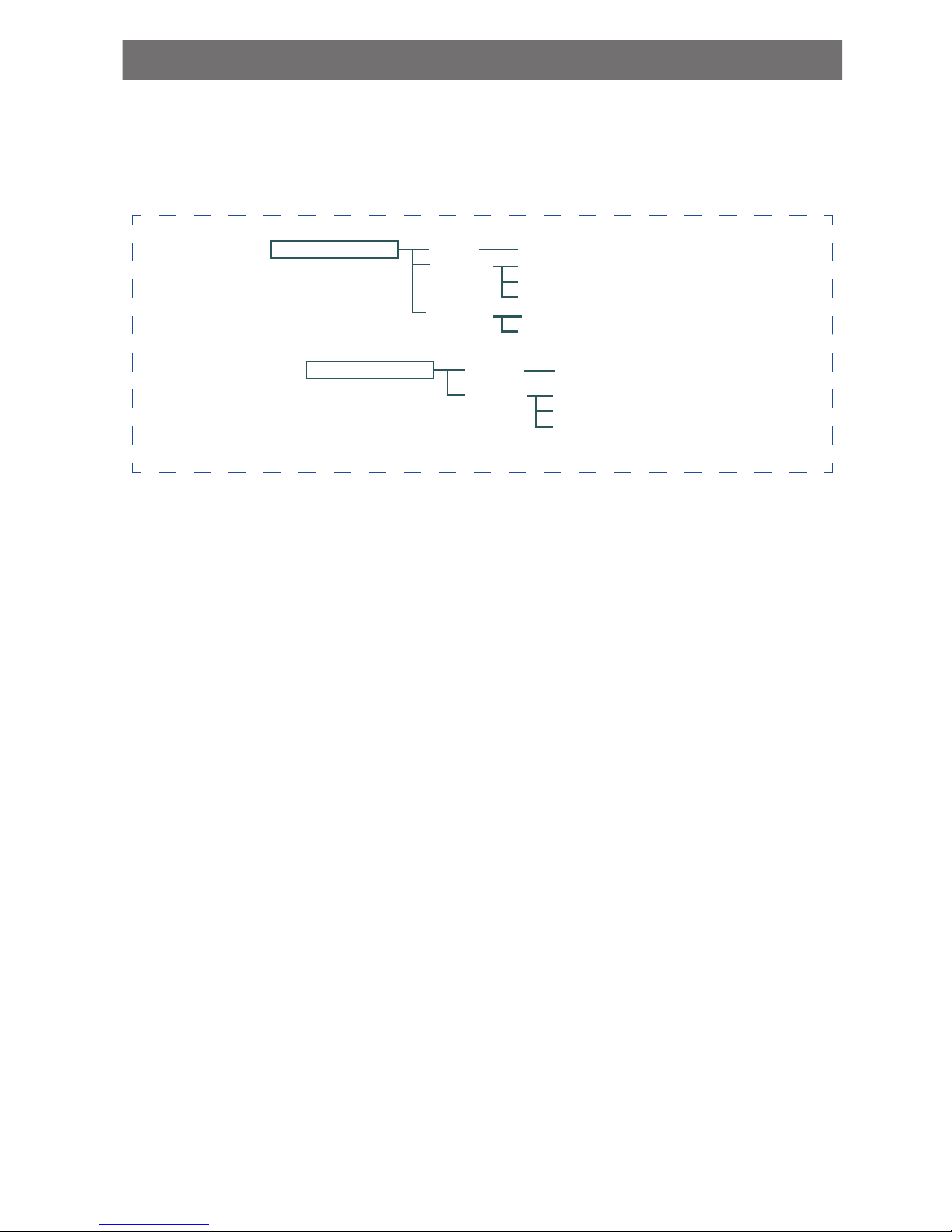
Program Menu Tree Options
Speed 1 (1-4)
Manual
Schedule
Egg Timer
Set Speed - Default: MANUAL
Set Speed
Set Start Time
Set Stop Time
Set Speed
Time
Speed 5 (5-8)
Schedule
Set Speed
Set Start Time
Set Stop Time
Disabled
Default: Disabled
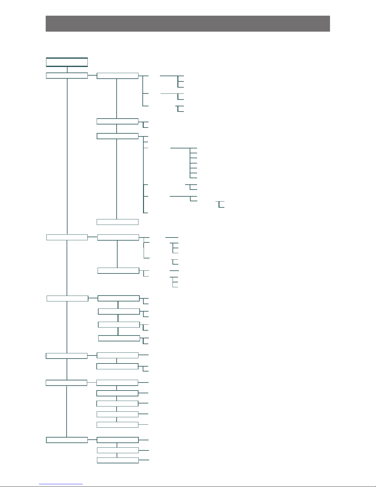
OPERATING THE PUMP 3/20
Press menu button to access menus
Date
Pump Address (1-16) - Default: 1
Screen Contrast (1-5) - Default: 3
Language
Manual
Schedule
Egg Timer
Set Speed - Default Spd 1-2: Manual
Set Speed
Set Start Time
Set Stop Time
Set Speed - Default Spd 3-4: Egg Timer
Time
Disabled / Enabled - Default: Enabled
Schedule
Set Speed
Set Start Time
Set Stop Time
Disabled
Default: Disabled
40° F - 50° F (4.4° C - 10° C) Default: 40° F (4.4° C)
Set Speed (450 RPM - 3450 RPM) Default 1000 RPM
SETTINGS
MENU
SPEED 1-8
EXT CONTROL
THERMAL MODE
Time
Hour Format
Months (1-12)
Days (1-31)
Years (2000-2050 Plus)
Hours (24hr Mode: 0-23) (12hr Mode: 1-12 AM & PM)
Minutes (0-60)
AM/PM - Default: AM/PM
Min Speed (450-1700 RPM) - Default: 450 RPM
Max Speed (1900-3450 RPM) - Default: 3450 RPM
English - Default: English
Português
Deutsch
Italiano
Nederlands
Français
Español
Temperature Unit Fahrenheit - Default F°
Celsius C°
Firmware Version
Password
Disabled - Default: Disabled
Enabled
Password Timeout (1 min. to 6 hrs.) - Default: 1 minute
Set Password (0000 - 9999) - Default: 1234
Stop Delay (0 min. to 10 min.) Default: 0 minutes
24 Hour
Device
Set Date and Time
Set Speed Max/Min
Speed 1-4
Speed 5-8
Disabled/Enabled
Set Speed
Pump Temperature
Set Speed (450-3450 RPM) - Default: 750 RPM
Set Speed (450-3450 RPM) - Default: 1500 RPM
Set Speed (450-3450 RPM) - Default: 2350 RPM
Set Speed (450-3450 RPM) - Default: 3110 RPM
Program 1
Program 2
Program 3
Program 4
Set Speed (450-3450 RPM) Default: 3450 RPM
Quick Clean Duration (1 min. to 10 hrs.) Default: 10 minutes
Time Out Duration (1 min. to 10 hrs.) Default: 3 hours
FEATURES
Quick Clean
Time Out
(1 min. to 30 min.) Default: 11 minutes
Disabled / Enabled - Default: Enabled
(1 - 10) Default: 5
(1 sec. to 10 min.) Default: 20 seconds
PRIMING
Disabled/Enabled
Max Priming Time
Priming Range
Priming Delay
Priming Speed
Set Speed (2400-3450 RPM) - Default: 3450 RPM
Alarm Log (1-10)
Stop Delay (0 min. to 10 min.) Default: 0 minutes
Stop Delay (0 min. to 10 min.) Default: 0 minutes
Stop Delay (0 min. to 10 min.) Default: 0 minutes
INTELLIFLO® VSD2 PUMP MENUS
14
 Loading...