

Page 1
INTELLICENTER® CONTROL SYSTEM
Pool Spa Features Lights
Air Temp 65° F
Schedule Usage Chemistry Status
3 3
8:00 A.M.
6.50
0
4
84°
78°
FOR POOL AND SPA
®
IMPORTANT SAFETY INSTRUCTIONS
READ AND FOLLOW ALL INSTRUCTIONS
SAVE THESE INSTRUCTIONS
INSTALLATION GUIDE
Page 2

Page 3
i
IMPORTANT WARNING AND SAFETY INSTRUCTIONS
READ AND FOLLOW ALL WARNING AND SAFETY INSTRUCTIONS
SERIOUS BODILY INJURY OR DEATH CAN RESULT IF THIS PRODUCT (UNIT) IS NOT
INSTALLED AND USED CORRECTLY.
INSTALLERS, POOL OPERATORS AND POOL OWNERS MUST READ THESE
WARNINGS AND ALL INSTRUCTIONS BEFORE USING THIS PRODUCT. This Guide
provides installation and operation instructions for the product. Consult Pentair
Water Pool and Spa, Inc. (“Pentair”) with any questions regarding this
product.
This product is intended for use in swimming pool applications only.
Most states and local codes regulate the construction, installation, and operation of public pools and spas, and
the construction of residential pools and spas. It is important to comply with these codes, many of which directly
regulate the installation and use of this product. Consult your local building and health codes for more information.
™
This guide provides installation and operation instructions for the IntelliCenter
Pentair Water Pool and Spa, Inc. with any questions regarding this equipment (see “Customer Service/Technical
Support”, page ii).
Attention Installer: This guide contains important information about the installation,
operation and safe usage of this product. Give this guide to the owner and/or operator of this equipment after
installation.
Attention User: This manual contains important information that will help you in operating and maintaining this
filter. Please save it for future reference.
Attention User: This Guide contains important information that will help you in operating and maintaining this
product. Please retain it for future reference. Read the entire Installation Guide and all related warning labels
before installing this product or attempting to use, service or adjust the IntelliCenter™ Control System. Read the
operating instructions and warnings for all equipment in the pool circulating system before operating. Failure to
follow safety warnings and instructions can result in severe injury, death, or property damage.
Call (800) 831-7133 for additional free copies of this Guide or replacement safety labels.
Control System. Consult
This product is designed and manufactured for safe and reliable service when installed, operated and
maintained according to the information and installation codes referred to in this Guide.
property. Always disconnect the power to the pool light at the circuit breaker before servicing the light.
Failure to do so could result in death or serious injury to serviceman, pool users or others due to
electrical shock.
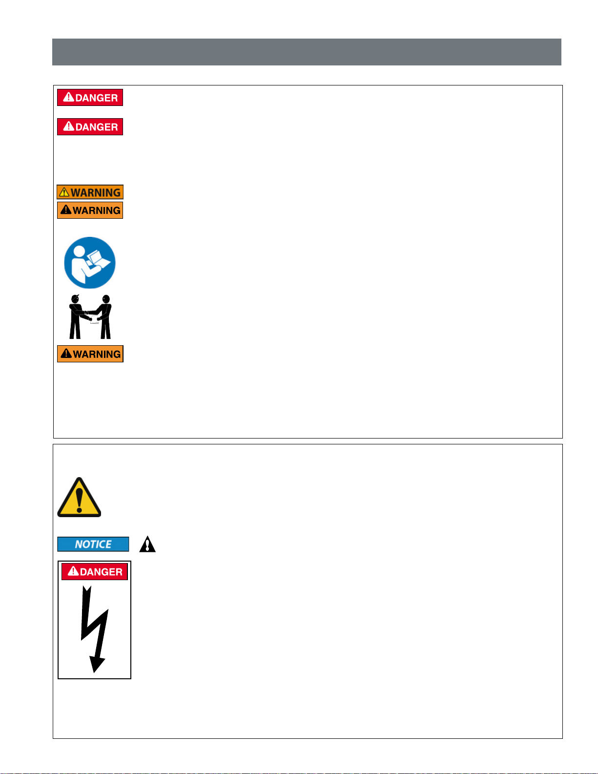
This is a safety alert symbol. When you see this symbol in this manual or on the product, look for
one of the following signal words; DANGER, WARNING, CAUTION and NOTICE and comply with the
information. Be alert to the potential hazard. Ensure to read and comply with all of the warnings and
cautions in this manual.
Risk of Electrical Shock or Electrocution!
- Always disconnect power at the circuit breaker before servicing the load center.
Improper installation can create an electrical shock hazard that can result in death
or serious injury.
This product must be installed by a licensed or certified electrician or a qualified
pool professional in accordance with the current National Electrical Code (NEC),
NFPA 70 or the Canadian Electr ical Code (CEC), CSA C22.1. All applicable local
installation codes and ordinances must also be adhered to. Improper installation
will create an electrical hazard which could result in death or serious injury to pool
users, installers or others due to electrical shock, and may also cause damage to
IntelliCenter Control System Installation Guide
Page 4
ii
IMPORTANT WARNING AND SAFETY INSTRUCTIONS
Water temperature in excess of 100° F (37.7° C) may be hazardous to your health.
Prolonged immersion in hot water may induce hyperthermia. Hyperthermia occurs
when the internal temperature of the body reaches a level several degrees above
normal body temperature of 98.6° F (37° C.). Effects of hyperthermia include:
(1) Unawareness of impending danger. (2) Failure to perceive heat. (3) Failure to
recognize the need to leave the spa. (4) Physical inability to exit the spa. (5) Fetal
damage in pregnant women. (6) Unconsciousness resulting in danger of drowning.
The use of alcohol, drugs, or medication can greatly increase the risk of fatal
hyperthermia in hot tubs and spas.
A pool or spa pump must be installed by a qualified pool and spa service professional
in accordance with the current National Electrical Code and all applicable local codes
and ordinances. Improper installation may create an electrical hazard which could
result in death or serious injury to pool users, installers, or others due to electrical
shock, and may also cause damage to property.
The use of alcohol, drugs, or medication can greatly increase the risk of fatal hyperthermia
in hot tubs and spas. This product is intended to control heaters with built-in high limit
circuits ONLY. Failure to do so may cause property damage or personal injury.
Do not use this product to control an automatic pool cover. Swimmers may become
entrapped underneath the cover.
For units intended for use in other than single-family dwellings, a clearly labeled
emergency switch shall be provided as part of the installation. The switch shall be readily
accessible to the occupants and shall be installed at least five (5) feet (1.52 m) away,
adjacent to, and within sight of, the unit.
Except for listed spa-side remote controls, install a minimum of five (5) feet (1.52 m) from
the inside wall of the pool and spa.
The electrical supply for this product must include a suitably rated switch or circuit
breaker to open all ungrounded supply conductors to comply with the current National
Electrical Code (NEC), NFPA 70 or the Canadian Electrical Code (CEC), CSA C22.1.
All applicable local installation codes and ordinances must also be adhered to. The
disconnecting means must be readily accessible to the tub occupant but installed at
least five 5ft. (1.52 m), (Canada 3 m (9.75 ft) from the inside wall of the pool.
Use only copper supply conductor’s rated for 60C/75C sized based on ampacity
to support all loads (refer to NEC tables). Load center input supply to be
protected by 150 Amp Maximum, 240 VAC Main Circuit Breaker.
For information about the Virginia Graeme Baker Pool and Spa Safety Act, contact the Consumer Product Safety
Commission at (301) 504-7908 or visit www.cpsc.gov.
NOTE: Always turn off all power to the pool pump before installing the cover or working on any suction outlet.
Two Speed Pump Controls Notice (Title 20 Compliance)
Please read the following important Safety Instructions - When using two-speed pumps
manufactured on or after January 1, 2008, the pump’s default circulation speed MUST be set to the
LOWEST SPEED, with a high speed override capability being for a temporary period not to exceed one
normal cycle, or two hours, whichever is less.
IntelliCenter Control System Installation Guide
Page 5

iii
IMPORTANT WARNING AND SAFETY INSTRUCTIONS
FCC Standard - 47 CFR Part 15, Subpart C (Section 15.247). This version is limited to chapter 1 to chapter 11 by
specified firmware controlled in the U.S.A.
Notice: In order to comply with FCC RF Exposure requirements, a minimum separation distance of 8 in (20 cm) must be
maintained between the equipment and all persons during normal operation.
®
Canada - Industry Canada (IC) - The IntelliCenter
of Industry Canada. (1999). Operation is subject to the following two conditions: (1) this device may not cause interference,
and (2) this device must accept any interference, including interference that may cause undesired operation of the device.
The device complies with industry Canada’s License Exempt RSSs. Operation is subject to the following: (1) This device
may not cause interference; and (2) This device must accept interference that may cause undesired operation of the
device.
Le dispositif est conforme à la licence d’Industrie Canada Exempt CNR. Le fonctionnement est soumis à la suivante.
(1) Ce ne doit pas provoquer d’interférences ; et (2) Cet appareil doit accepter les interférences qui peuvent causer un
mauvais fonctionnement de l’appareil.
This Class B digital apparatus complies with Canadian ICES-003.Cet appareil numérique de la classe B est conforme à
la norme NMB-003 du Canada. The term “IC” before the certification / registration number only signifies that the Industry
Canada technical specifications were met.
Instruction to user - The IntelliCenter Control System and IntelliChlor SCG device has been tested and found to comply
with the limits for a Class B digital device, pursuant to Part 15 of the FCC Rules. These limits are designed to provide
reasonable protection against harmful interference in a residential installation. The IntelliCenter Control System and
IntelliChlor SCG product device generates, uses and can radiate radio frequency energy and, if not installed and used
in accordance with the instructions, may cause harmful interference to radio communications. However, there is no
guarantee that interference will not occur in a particular installation. If this device does cause harmful interference to
radio or television reception, which can be determined by switching the device off and on, the user is encouraged to try to
correct the interference by one or more of the following measures:
• Reorient or relocate the receiving antenna.
• Increase the separation between the equipment and receiver.
• Connect the equipment into an outlet on a circuit different from that to which the receiver is connected.
• Consult the dealer or an experienced radio/TV technician for help.
Control System and IntelliChlor® SCG device complies with RSS210
General Installation Information
1. All wor k must be performed by a licensed electrician, and must conform to all national, state, and
local codes.
2. Install to provide drainage of compar tment for electrical components.
3. If this system is used to control underwater lighting fixtures, a ground-fault interrupter (GFCI) must
be provided for these fixtures. Conductors on the load side of the ground-fault circuit-interrupter
shall not occupy conduit, junction boxes or enclosures containing other conductors unless such
conductors are also protected by a ground-fault circuit-interrupter. Refer to local codes for details.
4. A ter minal bar stamped is located inside the supply ter minal box. To reduce the risk of electr ic
shock, this terminal must be connected to the grounding means provided in the electric supply
service panel with a continuous copper wire equivalent in size to the circuit conductors supplying
this equipment (no smaller than 12 AWG or 3.3 mm). The bonding lug(s) provided on this unit
are intended to connect a minimum of one No. 8 AWG for US installation and two No. 6 AWG for
Canadian installations solid copper conductor between this unit and any metal equipment, metal
enclosures or electrical equipment, metal water pipe, or conduit within 5 feet (1.5 m) of the unit.
5. The electr ical supply for this product must include a suitably rated switch or circuit breaker to open
all ungrounded supply conductors to comply with in accordance with the current National Electrical
Code (NEC), NFPA 70 or the Canadian Electrical Code (CEC), CSA C22.1. All applicable local
installation codes and ordinances must also be adhered to. The disconnecting means must be
readily accessible to the tub occupant but installed at least 10 ft. (3.05 m) from the inside wall of
the pool.
6. GAS HEATER: This automation control system is designed to supply high voltage (120 VAC / 240
VAC) to a gas heater and override the thermostat in the heater’s control circuit. This automation
control system is intended to control gas heaters with a high temperature limit switch(s) safety
circuit.
IntelliCenter Control System Installation Guide
Page 6
iv
Pentair Water Pool and Spa
IMPORTANT SAFETY INSTRUCTIONS
For Installation of Electrical Controls at Equipment Pad
(ON/OFF Switches, Timers, and Automation Control Systems)
Install all electrical controls at equipment pad, such as on/off switches, timers,
and control systems, etc. to allow the operation (start-up, shut-down, or
servicing) of any pump or filter so the user does not place any portion of his/
her body over or near the pump strainer lid, filter lid or valve closures. This
installation should allow the user enough space to stand clear of the filter and
pump during system start-up, shut down or servicing of the system filter.
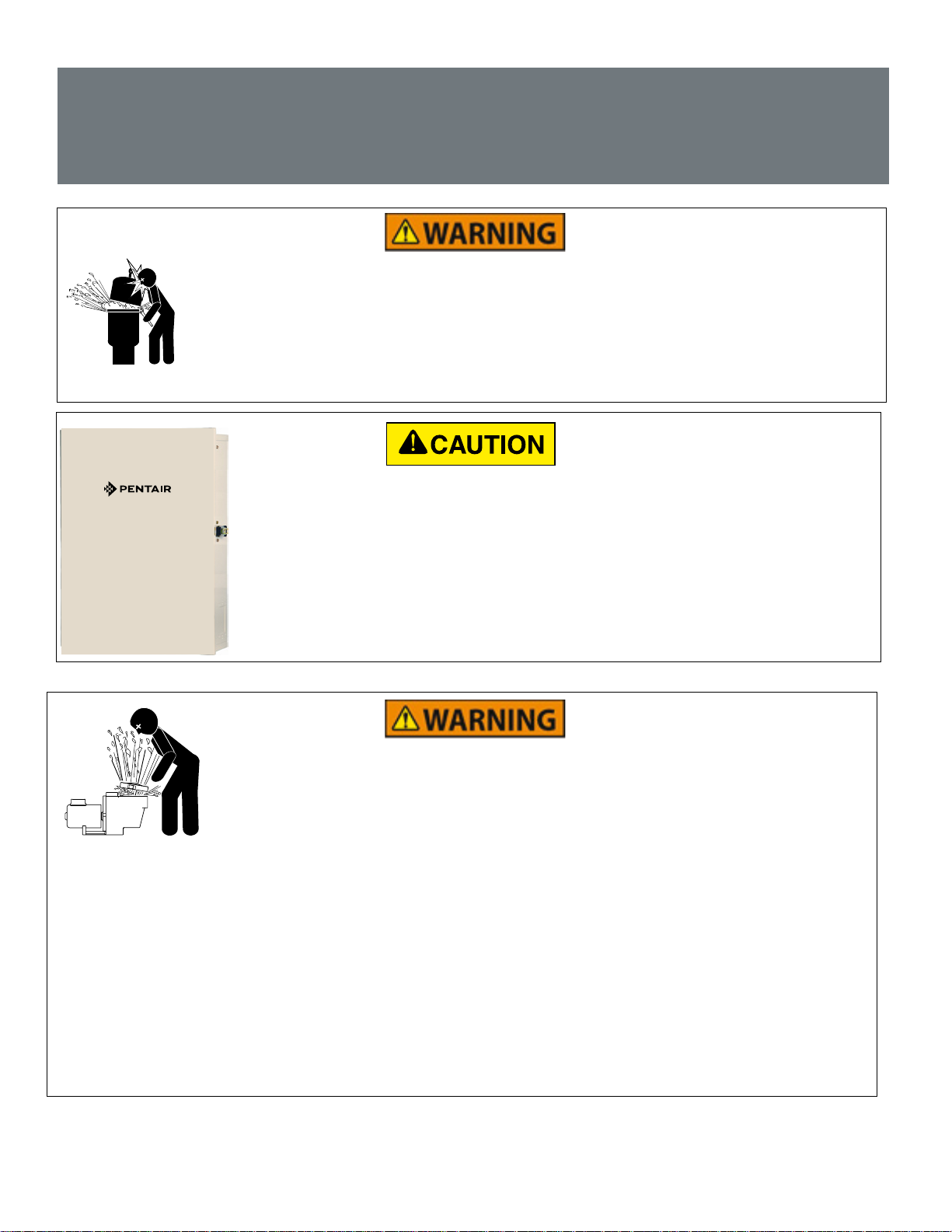
CAUTION! INSTALL POWER CENTER TO ALLOW USER ENOUGH SPACE TO
STAND CLEAR OF PUMP AND FILTER WHEN SERVICING.
HAZARDOUS PRESSURE: STAND CLEAR OF PUMP AND FILTER
DURING START-UP
Qualifications for Installers and Users
This product must be installed by a qualified pool technician in accordance with all applicable
local codes and ordinances. It must be serviced by someone who fully understands its operation.
Improper installation or servicing could result in death or serious injury to pool users, installers,
servicers, or others and may also cause damage to property.
If you are not familiar with your pool filtering system and/or heater, do NOT attempt to adjust or
service without consulting your dealer or a qualified pool technician.
Do not permit children to use this product.
IntelliCenter Control System Installation Guide
Page 7

v
Contents
IMPORTANT WARNING AND SAFETY INSTRUCTIONS .............................................................................i
General Installation Information ...................................................................................................................iii
Section 1: IntelliCenter Control System Overview .................................................................................1
Load Center and Power Center Installation Overview ................................................................................. 2
Load Center with bulit-in sub panel ..........................................................................................................3
Power Center without built-in sub panel ................................................................................................... 4
Preparing the Load Center and Power Center Enclosure ............................................................................7
Mounting the Load Center and Power Center .............................................................................................. 8
Load Center Conduit Knockout Locations ....................................................................................................9
Power Center Conduit Knockout Locations ..................................................................................................9
Installing Conduit and Conductors to the Enclosure .................................................................................. 11
Electrical Wiring High Voltage Connections ............................................................................................... 12
Main AC Power Connection (Load Center Circuit Breaker Sub panel) ..................................................12
Grounding and Bonding Connections .................................................................................................... 12
Circuit Breakers (Load Center with sub panel) ......................................................................................12
Load Center and Power Center High Voltage Connections ....................................................................... 13
GFCI and GFCB Connections ............................................................................................................... 13
Rewiring the IntelliCenter Control System Transformer for 240VAC .....................................................13-14
Accessing the IntelliCenter Control System Circuit Boards and Electronics .............................................. 15
Connecting IntelliCenter Control System Load Center Relays ..................................................................16
Installing V alve Actuators ......................................................................................................................18-20
Installing IntelliValve Valve Actuator ......................................................................................................21-25
Installing the Water Temperature Sensor ................................................................................................... 26
Installing the Ambient Air Temperature Sensor (for freeze protection) .......................................................26
Installing the Solar Temperature Sensor (Optional) ................................................................................... 27
Temperature vs. Resistance Data .......................................................................................................... 28
Connecting a Standard Gas Heater to the Load Center ............................................................................ 29
Connecting an IntelliFlo Pump to the Load Center .................................................................................... 30
Connecting a Pentair UltraTemp Heat Pump to the Load Center ............................................................... 31
Connecting a Pentair Hybrid Heat Pump to the Load Center ....................................................................31
Connecting the IntelliChlor (SCG) Power Cord to the Enclosure .............................................................. 32
Connecting the IntelliChlor (SCG) Communication Cable to a COM Port ................................................ 33
Connecting a Salt Chlorine Generator to the Load Center or Power Center ............................................. 34
Wiring Description (Hayward or Jandy Load Center COM Port) .......................................................... 34
Wiring the IntelliChem Controller to the Load Center ................................................................................ 34
Wiring the IntelliChlor SCG Transformer to Load Center Filter Pump Relay .............................................. 35
Rewiring the IntelliChlor SCG Transformer for 120VAC .............................................................................37
IntelliCenter Control System Installation Guide
Page 8

vi
Contents (continued)
Section 2: IntelliCenter Control System Start Up .................................................................................39
System Start-Up......................................................................................................................................... 39
Power on the Load Center and or Power Center .......................................................................................39
Start the Setup Wizard ............................................................................................................................... 39
IntelliCenter Control System Menu ............................................................................................................ 49
IntelliCenter Control System Test (Actuators/Pumps/Solar) ....................................................................... 50
Installing the Outdoor Control Panel in the Load Center or Power Center ................................................52
IntelliCenter Control System Personality Boards .......................................................................................53
IntelliCenter Control System Outdoor Control Panels ................................................................................54
IntelliCenter Control System Load Center Wiring Diagram ........................................................................55
IntelliCenter Control System Power Center Wiring Diagram ......................................................................56
IntelliCenter Control System Wireless Connections Diagram ....................................................................57
IntelliCenter Control System Personality Cards .........................................................................................58
IntelliCenter Control System Kits .............................................................................................................. 60
IntelliCenter Control System Components ................................................................................................. 61
Load Center or Power Center ................................................................................................................ 61
IntelliCenter Control System Personality Kit Descriptions .........................................................................61
IntelliCenter Control System Expansion Kits ............................................................................................ 62
Optional IntelliCenter Control System Expansion Enclosure ................................................................ 62
IntelliCenter Control System Personality Kit Contents ...............................................................................63
Optional IntelliCenter Control System Kit Contents ................................................................................... 63
IntelliCenter Control System Upgrade Kits .................................................................................................63
IntelliCenter Control System Replacement Parts List ................................................................................ 64
IntelliCenter Control System Accessory Equipment .................................................................................. 64
IntelliCenter Control System Configurations and Models .......................................................................... 65
Troubleshooting - Error Messages/Error Codes ...................................................................................66-77
Plumbing Requirements ............................................................................................................................ 78
Equipment Location ............................................................................................................................... 79
Over-The-Air (OTA) Firmware Updates ..................................................................................................... 81
Glossary .................................................................................................................................................... 84
CUSTOMER SERVICE / TECHNICAL SUPPORT
Customer Service
8 AM to 8 P M —
Phone: (800) 831-7133
Fax: (800) 284-4151
Visit www.pentair.com
P/N 522989 Rev. F 12/2020
IntelliCenter Control System Installation Guide
Technical Support
Sanford, North Carolina (8 AM to 8 PM ET)
Phone: (919) 566-8000
Fax: (919) 566-8920
Moorpark, California (8 AM to 5 PM PT)
Phone: (805) 553-5000
Fax: (805) 553-5515
Page 9

Section 1
IntelliCenter® Control System Overview
Welcome! Your Pentair IntelliCenter Control System will change the way you view pool and spa
controls. This innovation in pool and spa automation offers complete freedom for you while having full
automation control over your pool, spa, lights, heater, cleaners and much more. You can now schedule
multiple start and stop times to control your lights, heater, spa jets, and filter pumps. The historical
usage data feature provides a convenient way to help you conserve energy. Using an iPhone®, iPad®
mobile digital device or an Android® wireless device, you can now control your pool and spa from
anywhere inside or outside your home. The IntelliCenter Control System is a scalable system that can
be used with popular home automation systems.
This manual describes how to install the IntelliCenter Control System and associated equipment.
Features
1
• 4” x 3” capacitive touch sensitive color touch screen.
• Day Time and Night Time color screen modes
• Multifunction Schedules/Programs
• Adjustable schedule timer for easy system scheduling
• 100 Schedules/Programs
• 32 Feature Circuits: Allow additional speeds on a variable
speed pump or an actuator to be assigned without using
an existing auxiliary circuit.
• 16 Groups: Assign groups of lighting and AUX circuits to
be controlled by a single button
• Supports up to 16 IntelliFlo® VF and VS Pumps
• Supports up to four Spa Command® and iS10 Spa Side
Remotes, and two iS4 and one QuickTouch® II Wireless
Spa Side Remotes
• Supports up to two Indoor Control Panels
• Supports IntelliBrite® LED Color lights
• Valves: Intake/Return plus A and B valve circuits.
Expandable up to 10 valves (shared equipment).
• Indoor Control Panel, Wireless Hand-Held Remote,
Outdoor Control Panel
• IntelliChem® Controller: Supports one per body.
• IntelliChlor® Salt Chlorine Generator: Supports one per
bosy
Note: See page 63 for IntelliCenter Control System
models, part numbers, and replacement kits.
• 40 Auxiliary Circuits (up to three Expansion
Enclosures)
• Spa Manual Heat Function
• Support for two Bodies of Water
• Supports multiple heater connection capability
(starting from software release v1.047)
• Over-The-Air Software Updates: See page 84.
(starting from software release v1.047)
• Spa Side Control Enable/Disable
• Solar Heating Option/Support
• 16 Heat Pump Support: RS-485 Support, Heat
Pump Cooling Support.
• Real Time Clock
• Assignable Circuit Names and Custom Circuit
Names
• Special Circuit Types/Function
• Two Speed Pump Support
• English/Metric Support
• Sensor Calibration
• Passcode Protection
• USB port for use with a standard flash drive.
Save the system’s configuration and upgrade the
system’s firmware
• WiFi Wireless Connection: Supports wireless
Internet connection for remote system control
Note: See page 69 for IntelliCenter Control System
Troubleshooting Error Messages and Error Codes for heaters,
pumps, IntelliChem and IntelliChlor.
Page 10

2
Section 2
IntelliCenter® Control System Installation
Overview
RISK OF ELECTRICAL SHOCK. BEFORE REMOVING THE HIGH VOLTAGE
COVER PANEL FROM THE ENCLOSURE SWITCH OFF THE
MAIN POWER AT THE HOME AT THE MAIN CIRCUIT BREAKER BOX.
This manual describes how to install, configure and operate the IntelliCenter Control System.
Please take time to read through this manual to familiarize yourself with the IntelliCenter Control
System.
Please read the following guidelines carefully:
• The IntelliCenter Control System Load Center and/or Power Center must be installed at the
equipment pad.
• AC power for the Load Center must be provided from the main circuit breaker panel located at the
house.
• All electrical equipment, except for UL Listed spa-side remote switches, must be installed no
less than five (5) feet (1.5 m), (Canada, 3 mm (9.75 ft) from pool and/or spa, and comply with
all national, state, and local codes (UL Listed spa-side remote switches may be installed at near
waterline).
• Install the Load Center no less than five (5) feet (1.5 m) from pool, spa, and hot tub. Additionally,
the installation shall allow the user enough space to stand clear of the filter and pump during
system start-up, as explained on page vi.
• The TYPE 3R “Rainproof” enclosure can be mounted outside or inside of a pool equipment shed or
other enclosure.
• Before choosing the final location for the enclosure, consider the length of all of the conductors that
will have be connected to the enclosure. Make sure to consider cable lengths for the sensors to the
Load Center location. The air temperature sensor cable is three (3) feet (91.44 cm) long and the
water temperature sensor cable is 25 feet (7.62 m) long.
• Mount the Load Center on a flat vertical surface so the conduit knockouts are located at the bottom
of the enclosure. Upper and lower brackets are provided to mount the enclosure.
• DO NOT mount the enclosure horizontally. Water can enter the conduit knockouts and cause
damage to the system and an electrical shock hazard. Install with conduit knockouts down.
• Consider the Load Center location when routing conduit carrying the AC power to the Load Center,
and the conduit that will be run to the high voltage equipment.
• Install the Load Center so that drainage is provided for all electrical components.
• Motors should be listed for pool and spa applications and have built-in thermal protection.
• Allow at least 5 ft (1.5 m) of unobstructed access to the front of the Load Center for the owner or
service personnel.
• The Load Center provides grounding screw terminals for grounding all equipment. All equipment
including the Load Center enclosure must be bonded to earth ground.
IntelliCenter Control System Installation Guide IntelliCenter Control System Installation Guide
Page 11
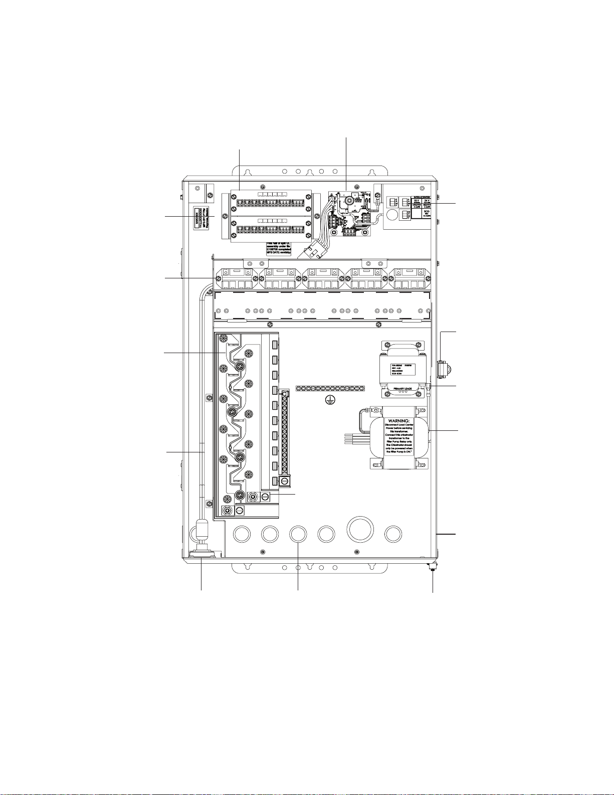
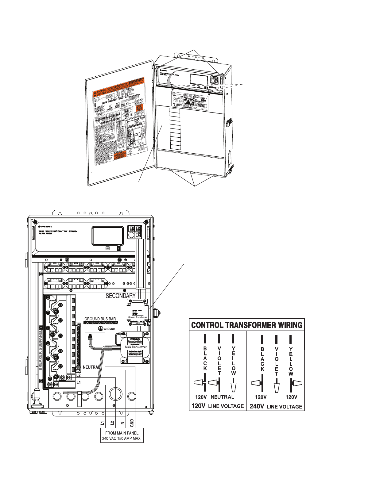
IntelliCenter® Control System Load Center (with built-in sub panel)
The IntelliCenter Control System load center should be installed at the equipment pad. The AC power to
the load center is provided from the main-panel circuit breaker located at the house.
3
Optional Serial COM Port Expansion Board
(Brackets support two boards)
Low voltage
compartment.
Outdoor Control
Panel with
Main Circuit Board
(not shown)
High V oltage Relays
(1-5) with additional
five (5 ) relays or
2-Speed Pump relay
(optional)
Circuit breaker
base 150 AMP
(Sub panel)
Low voltage raceway
(Air and water
temperature sensors,
motorized valves,
indoor control panel,
spa side
remote, and wireless
antenna)
IntelliChlor SCG circuit board (optional)
18 V, 5 AMPS ORG/
WHT (System).
24 V, 4 AMPS, RED/
WHT (Valves)
12 AMPS, SCG,RED
circuit breakers
Optional High Voltage Relays (5-10)
Door spring latch
(padlock optional)
Control System
transformer:
Ground buss bar
120VAC, 2.5A,
240VAC, 1.3A,
50/60 Hz
Optional IntelliChlor Salt
Low voltage raceway
Chlorine
Generator (SCG) and
power supply
transformer (SCG
AC Power
Connector
system only). 120VAC, 2A,
240VAC, 1A, 50/60 Hz
IntelliChlor (SCG)
cell connector socket
(optional)
Enclosure conduit knockouts
(see page 9): 1¼”, 1”, ¾” and
½” conduit knockouts (lower
and rear) for high voltage
Bonding lugs (two each)
No.8 AWG (US)
or
No.6 AWG (Canada)
output. 1” conduit
knockout (lower) for high
voltage input
IntelliCenter Control System Load Center
(26” H x 17” W x 5¼” D)
GFCI/GFCB
knockout (approved
rainproof cover required)
- Standard Single gang
box.
Page 12
4
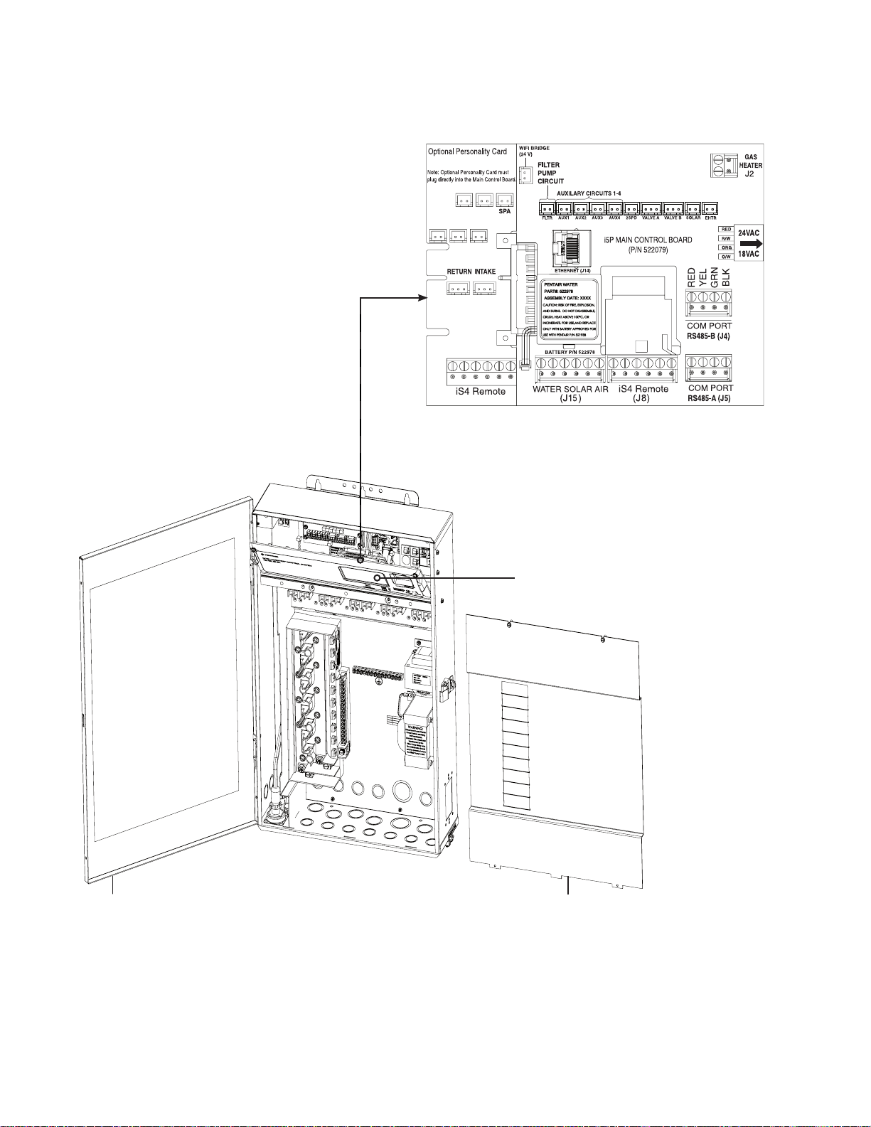
IntelliCenter® Control System Load Center (with built in sub panel) Continued
AUX 5 AUX 6
AUX 7 AUX 8 AUX 9
IntelliCenter Control System Main Circuit Board
(with i10PS optional expansion card shown)
Load Center
front door
IntelliCenter Control System
Outdoor Control Panel
(in open/fold down position)
High voltage
cover panel
IntelliCenter Control System Load Center
IntelliCenter Control System Installation Guide IntelliCenter Control System Installation Guide
Page 13
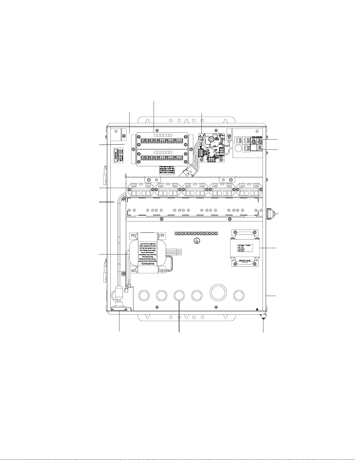
IntelliCenter® Control System Load Center (without built-in sub panel)
The IntelliCenter Control System Power Center (without sub panel) must be installed at the
equipment pad. AC power to the Power Center is provided from the electrical circuit breaker panel
(sub panel) installed at the equipment pad. The Power Center should be installed next to the sub
panel.
5
Low voltage compartment
Outdoor Control
Panel (not shown)
High V oltage Relays
(1-5) with additional
five (5 ) relays or
2-Speed Pump relay
(optional)
Low voltage raceway
(Air and water
temperature sensors,
motorized valves , indoor
control panel, spa side
remote, and wireless
antenna)
Optional IntelliChlor Salt
Chlorine
Generator power supply
transformer
(SCG system only).
120VAC, 2A,
240VAC, 1A,
50/60 Hz
Optional Serial COM Port Expansion Board
(Brackets support two boards)
IntelliChlor SCG circuit board (optional)
Optional High Voltage Relays (5-10)
Ground buss bar
Low voltage raceway
18 V, 5 AMPS ORG/
WHT
(System).
24 V, 4 AMPS, RED/
WHT (Valves)12
AMPS, SCG, RED
circuit breakers
12 AMP circuit
breaker for optional
IntelliChlor
®
Salt Chlorine
Generator
(24 V AC)
Door spring latch
(padlock optional)
System
transformer:
120VAC, 2.5A,
240VAC, 1.3A,
50/60 Hz
GFCI/GFCB
knockout
(approved
rainproof cover
required)
IntelliChlor (SCG)
cell connector socket
(optional)
IntelliCenter Control System Power Center (20” H x 17” W x 5¼” D)
(Front view with door and high voltage cover panel removed)
Enclosure conduit
knockouts: 1¼”, 1”,
¾” and ½” conduit
knockouts (lower and
rear) for high voltage
output. 1” conduit
knockout (lower)
for high voltage input
Bonding lugs (two each)
No.8 AWG (US)
or No.6 AWG (Canada)
Page 14
6
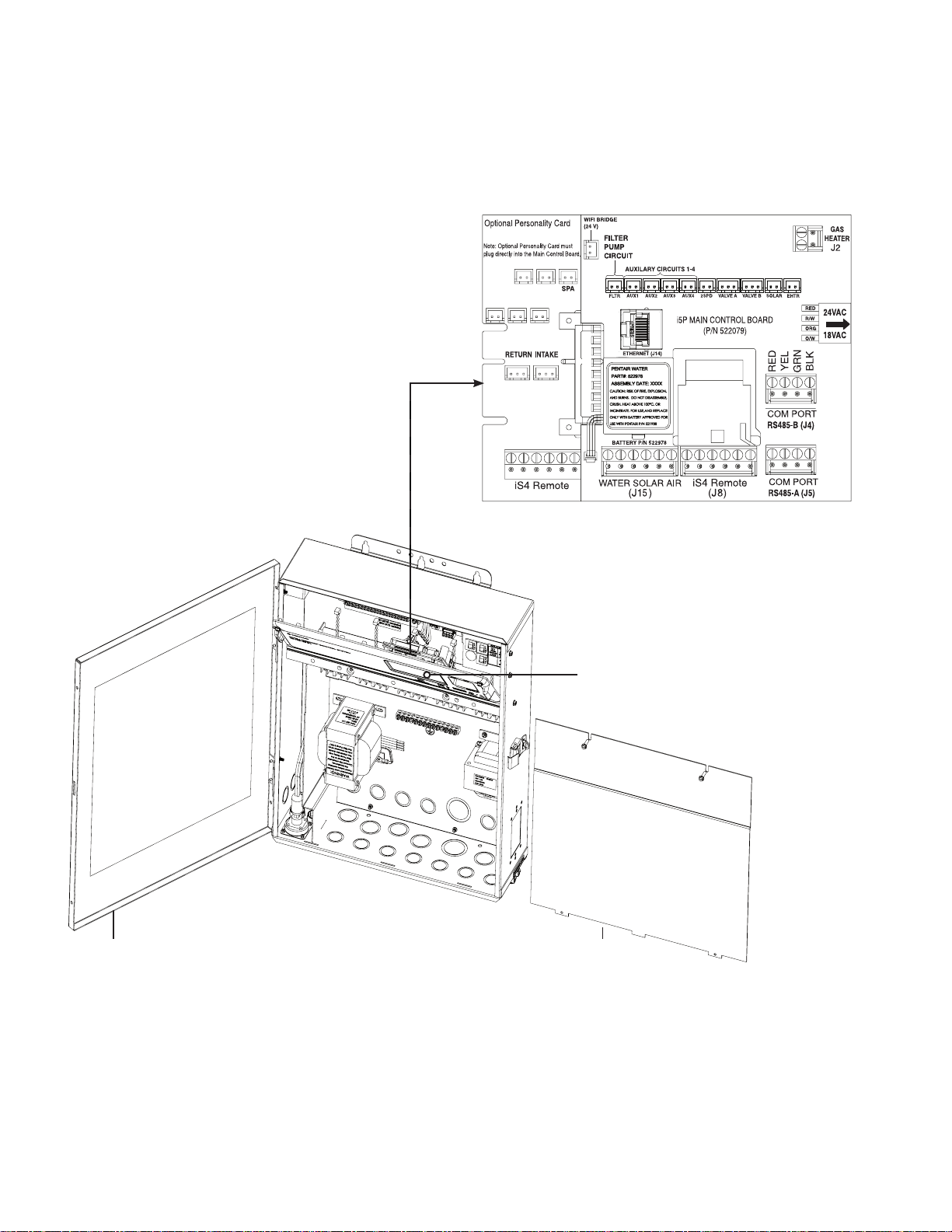
IntelliCenter® Control System Power Center (without sub panel) Continued
AUX 5 AUX 6
AUX 7 AUX 8 AUX 9
Power Center
front door
IntelliCenter Control System Main Circuit Board
(iS5 with optional Expansion Card shown)
IntelliCenter Control System
Outdoor Control Panel
(in open/fold down position)
High voltage
cover panel
IntelliCenter Control System Power Center
IntelliCenter Control System Installation Guide IntelliCenter Control System Installation Guide
Page 15
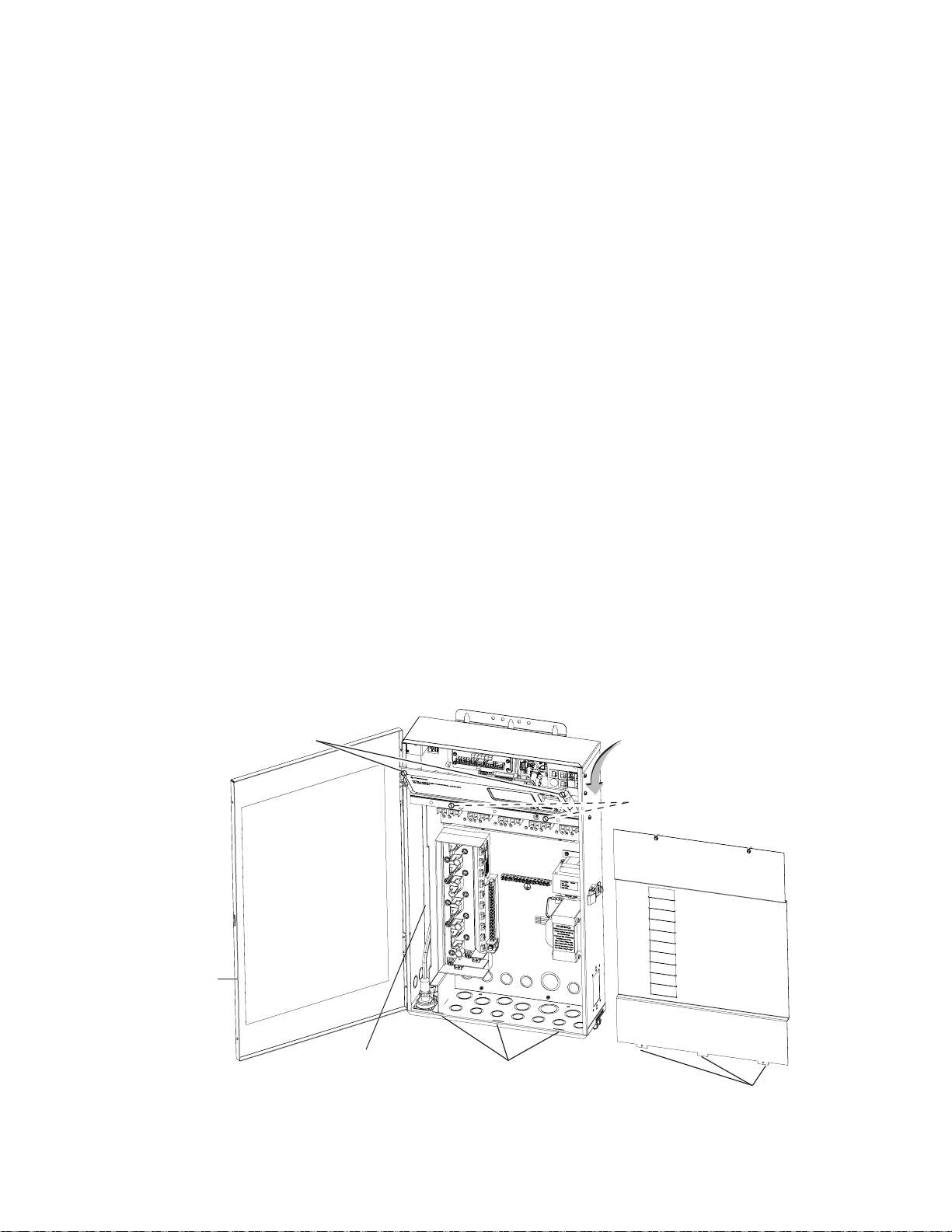
Preparing the IntelliCenter® Load Center and Power Center Enclosure
BEFORE INSTALLING THE LOAD CENTER AND POWER CENTER, ALWAYS
SWITCH OFF THE MAIN POWER into the home at the main circuit breaker box.
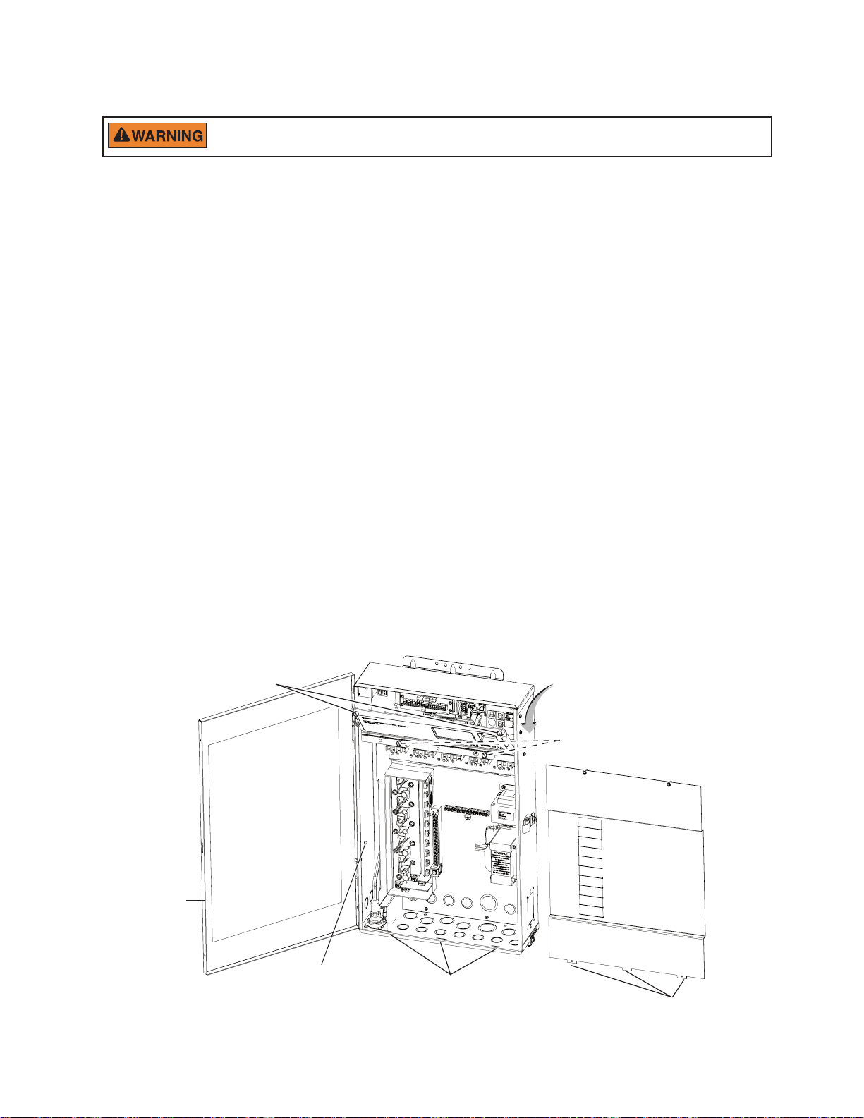
Before mounting the Load Center, first remove the front door and the high voltage cover panel to
access the enclosure conduit knockouts and low voltage raceway (see page 9 and 10).
To remove the Load Center or Power Center high voltage cover panel:
1. Unpack the Load Center from the shipping carton.
2. Unlatch the front door spring latch and open the front door.
3. Remove the two retaining screws from the High Voltage Cover Panel. Remove the panel from the
enclosure.
4. Loosen the two retaining screws securing from the top edge of the Outdoor Control Panel. Fold
down the Outdoor Control Panel to access the circuit board sockets connectors for the electrical
connections.
5. For new installation, proceed with:
• Mounting the Load Center / Power Center, page 7-8
• Load Center / Power Center Conduit Knockout Locations, page 9-11
• Installing Conduit and Conductors to the Enclosure, page 11
• Electrical Wiring and High Voltage Load Center Connections, page 12-14
• Electrical Wiring and High Voltage Connections, page 12-14
• Accessing the Control Circuit Boards and Electronics, page 15
• Connecting Relay Valve Actuators, Sensors, Gas Heater, Pumps, Sanitizers, page 16
6. After electrical connections have be completed; close the Outdoor Control Panel and tighten the
two retaining screws. Reinstall the High Voltage Panel: Insert the panel’s three tabs into the lower
slots on the enclosure. Secure the panel with the two (2) retaining screws. Close the front door and
secure with the latch.
7
Loosen Outdoor Control
Panel retaining screws
Front door
LOW VOLTAGE
RACEWAY
IntelliCenter Control System Load Center (Front View)
Flip down the Outdoor Control Panel to
access the Main Circuit Board and low
voltage compartment
Remove two (2) retaining screws
securing High Voltage Cover Panel
High Voltage Cover Panel slots (3)
High Voltage Cover Panel Tabs (3)
Page 16
8
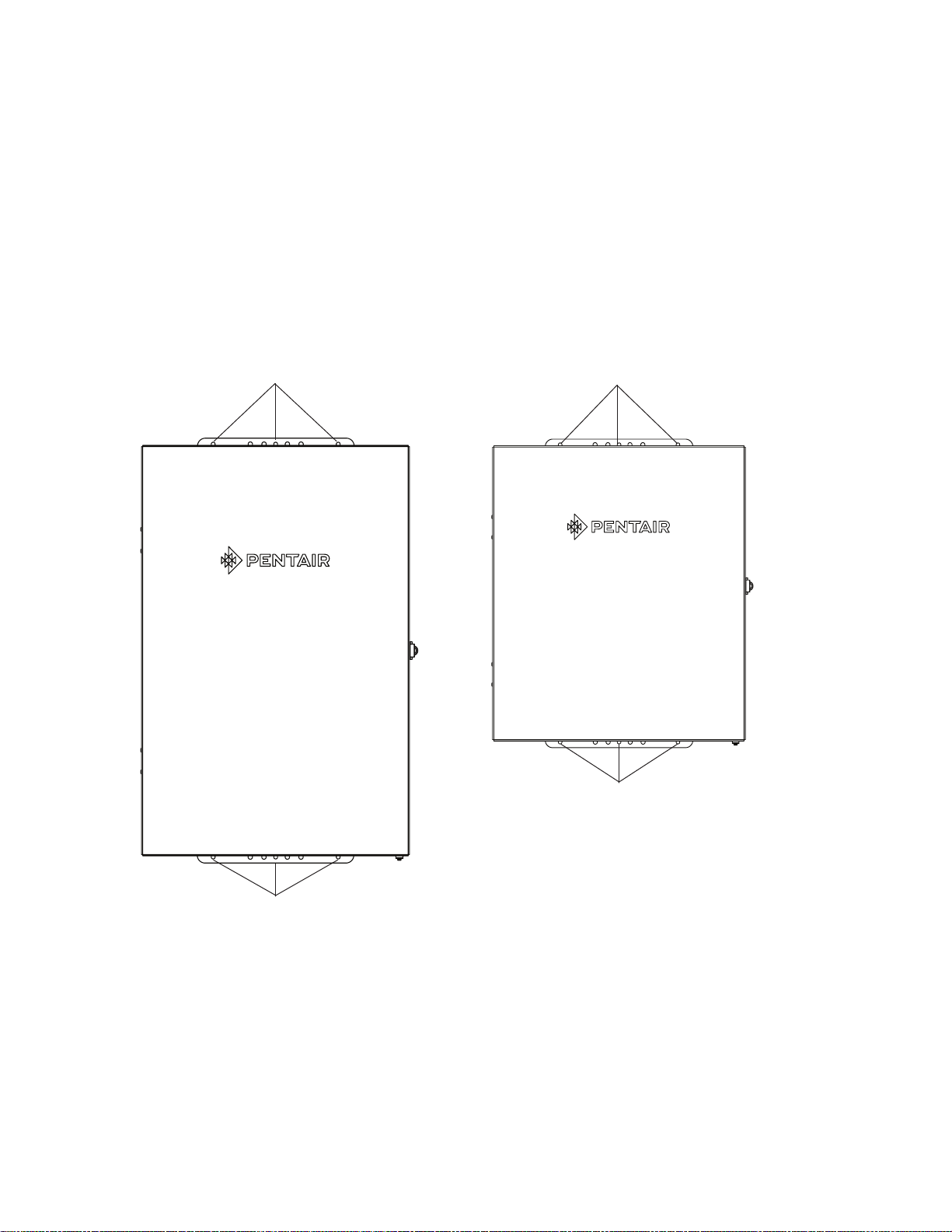
Mounting the IntelliCenter® Control System Load Center and Power Center
Mount the IntelliCenter Control System Load Center or Power Center on a flat vertical surface, such
as a wall or post at eye level, at least 5 ft. (1.5 m), (Canada 3 m (9.75 ft)) from the pool, spa or hot
tub.
To mount the Load Center or Power Center:
1. Position the enclosure against a vertical flat surface. If wall anchors are being used, support the
enclosure in position (horizontally level and square) against the surface and mark the bracket hole
pattern on the wall.
2. Secure the enclosure with three (3) screws in the top and lower mounting bracket holes. If using wall
anchors, drill and set the anchors and secure the enclosure with screws.
Top mounting bracket screw holes
Top mounting bracket screw holes
Lower mounting bracket screw holes
IntelliCenter Control System Power Center
(20” H x 17” W x 5¼” D)
Lower mounting bracket screw holes
IntelliCenter® Control System Load Center
(26” H x 17” W x 5¼” D)
IntelliCenter Control System Installation Guide IntelliCenter Control System Installation Guide
Page 17
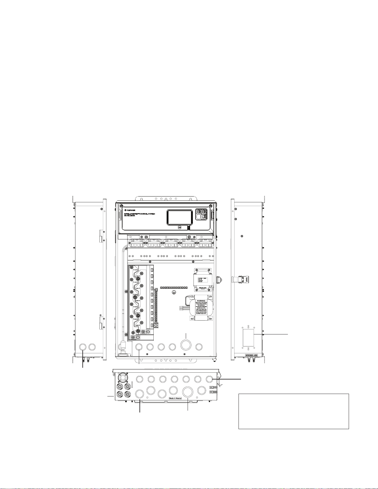
Load Center Conduit Knockout Locations
Before installing electrical conduits and connecting AC power to the IntelliCenter® Control System
Load Center or Power Center enclosure, read the following recommended guidelines:
• Determine the number of low and high voltage circuits being used in the Load Center or Power
Center. The conduit size and runs needed based on the conductor size, and the number of
conductors within the conduit. The enclosure conduit knockouts sizes are 1¼”, 1”, ¾” and ½”.
• Enclosure conduit knockouts for AC power are located on the sides, bottom and back of the
enclosure. Conduit knockouts sizes for AC power are: 1¼”, 1”, ½” and ¾”. It is recommended to use
1¼” x 1” conduit for the main AC power conductors.
• The Load Center and Power Center enclosure must be located a minimum of 5 ft. (1.5 m), (Canada
3 m (9.75 ft)) from the inside wall of pool or spa.
Remove the enclosure conduit knockouts as needed:
• Low voltage raceway has two ½” x ¾” conduit knockouts located on the left side and rear of the
enclosure.
• High voltage compartment has twelve ½” x ¾”, five ¾” x 1” and two 1¼” x 1” conduit knockouts
located on the bottom of the enclosure.
9
½” x ¾” conduit
knockout (2x) -
Low voltage only
¾” grommet fittings (4x)
(low voltage and
sensor conductors)
1¼” x 1”
½” x ¾” rear conduit knockout (5x)
¾” x 1” conduit
knockout (5x)
1¼” x 1”
conduit
knockout
Note: Sub panel
wiring: 14 AWG
minimum copper
conductors for relays
and other equipment
sized according to
the ampacity of the
load.
Optional GFCI/
GFCB Receptacle
knockout
(standard single
gang type 3R cover
required)
½” x ¾” conduit knockout (8x)
NOTE: DO NOT ROUTE LOW VOLTAGE
CONDUCTORS (VALVES, SENSORS etc.)
THROUGH THE HIGH VOL TAGE
KNOCKOUTS ON BOTTOM OF LOAD
CENTER.
IntelliCenter Control System Load Center (Lower, side and back panel knockout locations)
Page 18
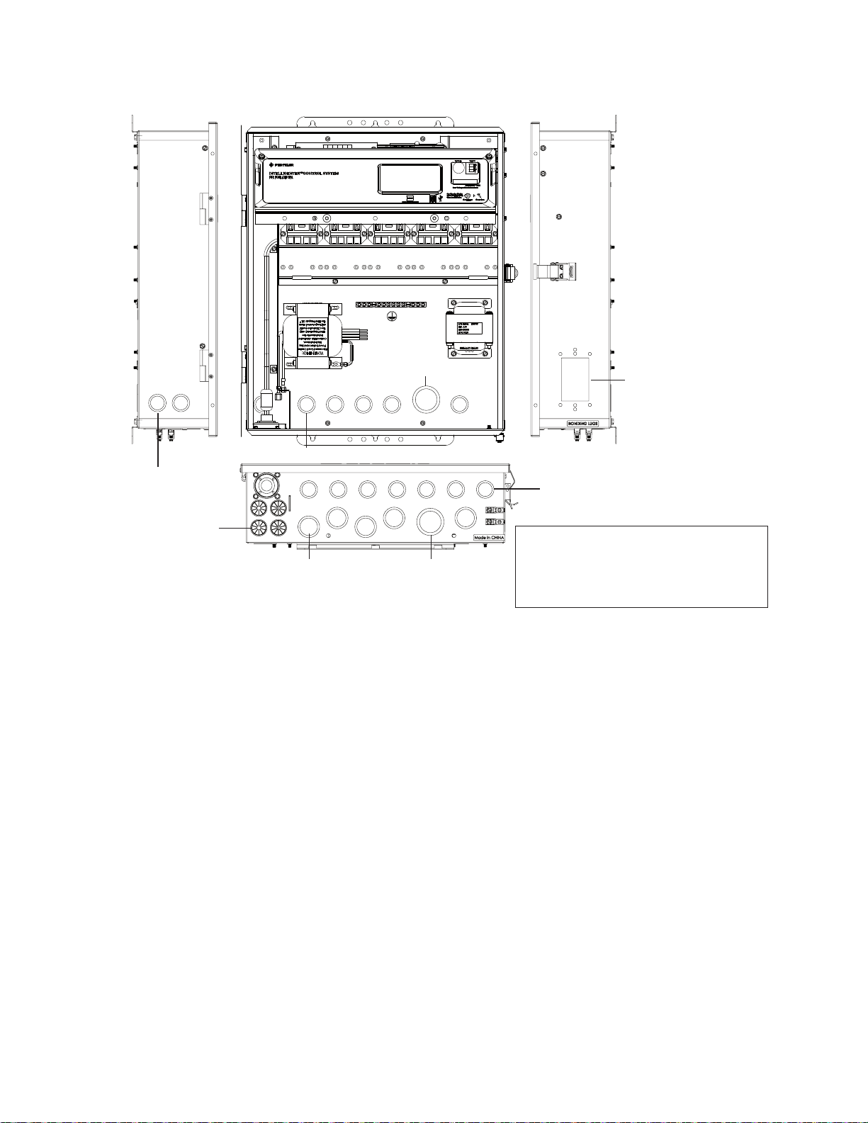
10
Power Center Conduit Knockout Locations
1¼” x 1”
½” x ¾” rear conduit knockout (5x)
½” x ¾” conduit
knockout (2x) -
Low voltage only
¾” grommet fittings
(4x) (low voltage and
sensor conductors)
¾” x 1” conduit
knockout (5x)
1¼” x 1”
conduit
knockout
Note: 14 AWG
minimum copper
conductors for relays
and other equipment
sized according to
the ampacity of the
load.
Optional GFCI/
GFCB Receptacle
knockout
(standard single
gang type 3R cover
required)
½” x ¾” conduit knockout (8x)
NOTE: DO NOT ROUTE LOW VOLTAGE
CONDUCTORS (VALVES, SENSORS etc.)
THROUGH THE HIGH VOL TAGE
KNOCKOUTS ON BOTTOM OF LOAD
CENTER.
IntelliCenter
®
Control System Power Center (Lower, side and back panel knockout locations)
IntelliCenter Control System Installation Guide IntelliCenter Control System Installation Guide
Page 19

Installing Conduit and Conductors to the Enclosure
Before installing electrical conduit to the enclosure, read the following recommended guidelines:
NOTE: All electrical installation, including electrical wiring methods and materials used to
complete the electrical installation of the IntelliCenter Control System MUST BE PERFORMED
BY A SERVICE PROFESSIONAL AND/OR UNDER DIRECT SUPERVISION OF A QUALIFIED
ELECTRICIAN in accordance with the National Electrical Code or the Canadian Electric Code, as
well as any local electrical codes in effect at the time of installation. Refer to NEC 680 (b) or CEC
687-060, 062, and 066 for further details.
11
• Determine the number of low and high voltage circuits being used in the IntelliCenter
®
Control
System Load Center or Power Center. The conduit length is based on the conductor size, and the
number of conductors within the conduit. The number of pieces of equipment to be controlled
will dictate the size of the conduit. DO NOT RUN HIGH VOLTAGE AND LOW VOLTAGE
CONDUCTORS IN THE SAME CONDUIT.
• Use 14 AWG minimum to 6 AWG maximum 140°/158° F (60°/70° C) or better copper conductors for
relay circuits depending on the load requirement. Be sure to follow all NEC regulation safety codes
for the number and size of conductors that can be installed in various sizes of conduit.
• Supply conductor must be sized to support all loads. The maximum supply current must NOT
exceed 150 AMP at 120 VAC/240 VAC.
• Supply circuit must be protected by suitable breaker rated no higher than 150 AMP. If one relay is
used for more than one device, verify that the total current draw (all equipment) does not exceed the
current rating of the circuit.
• The IntelliCenter Control System automation control circuit board requires 120 VAC, 3A power to
®
operate the control logic circuits and the optional IntelliChlor
Salt Chlorine generator. This power
should be connected to one of the circuit breakers in the sub panel.
• To avoid obstruction into the Load Center or Power Center, when using electrical conduit complete
the installation of the conduit before concrete is poured. Also, underground conduit should be
positioned in well compacted soil. Ensure that all conduit joints are well sealed and watertight.
Page 20

12
Electrical Wiring and High Voltage Connections
TO AVOID AN ELECTRICAL HAZARD - Do not connect the power
source conductors to the Load Center circuit breaker until all electrical
connections for all loads (heaters, pumps, motorized valves, and lights etc.)
have been completed.
Main AC Power Connection (Load Center Circuit Breaker Sub panel)
The IntelliCenter® Control System Load Center with circuit breaker sub panel is rated for 150 AMP
maximum Single Phase (3 conductor). Run properly rated conductors (L1,L2, N, and GROUND) from
the primary house electrical panel to the main AC power connections on the Load Center circuit breaker
base. The connection at the main house panel should be to a 240 VAC circuit breaker rated at 150 AMP
maximum.
Grounding and Bonding Connections
Connect a ground conductor from the primary house electrical panel to the Load Center or Power Center
GROUND BUS BAR (see page 3 and 5). Also ground each piece of high voltage (120 VAC or 240VAC)
equipment that is connected to the Load Center or Power Center relays or circuit breakers. Also connect
the Load Center and Power Center to the pool bonding system using 8 AWG (6 AWG for Canada)
conductor. There are two (2) GROUND LUGS provides on the bottom of the Load Center and Power
Center.
Circuit Breakers (Load Center with sub panel)
Circuit Breakers are to be supplied and installed by the site installer. For recommended circuit breaker
types, refer to the circuit breaker chart on the inside front door of the Load Center or Power Center. Be sure
to follow all manufacturer’s circuit breaker rating requirements. Some pool equipment require connection to
ground fault circuit breakers (GFCI). Check local and NEC (CEC) codes for these requirements.
Note: For recommended field conductor gauge usage, refer to conductor size listed on the circuit
breaker label.
Note: Wiring to Load Center: 14 AWG minimum copper conductors for relays and other equipment sized
according to the ampacity of the load.
IntelliCenter Control System Installation Guide IntelliCenter Control System Installation Guide
Page 21
Load Center and Power Center High Voltage Connections
TO AVOID AN ELECTRICAL HAZARD - Do not connect the power
source conductors to the Load Center circuit breaker until all electrical
connections for all loads (heaters, pumps, motorized valves, and lights etc.)
have been completed.
GFCI and GFCB Connections
• Use the rectangular knockout on the right side of the Load Center and Power Center
enclosure to mount an approved GFCI or GFCB with rainproof type 3R cover (supplied by
installer) for direct connection of underwater pool and spa lights.
• Use the one of the three low voltage raceway 3/4” holes located on the underside of the
enclosure for the temperature sensor conductors (see page 3 and 5).
NOTICE: For the AC supply conductor into the Load Center and Power Center from the main
circuit breaker at the house, use three conductors, one each for red, black, and white (or
red, red and black for 240 VAC). The maximum load is 150 AMP at 120 VAC/240 VAC 60 Hz/50
Hz. These conductors should be secured to supply side of circuit breaker base. For the
main AC power conduit, it is recommended to use the 1¼” x 1” conduit knockout located
directly under the enclosure circuit breaker (see page 3 and 5).
13
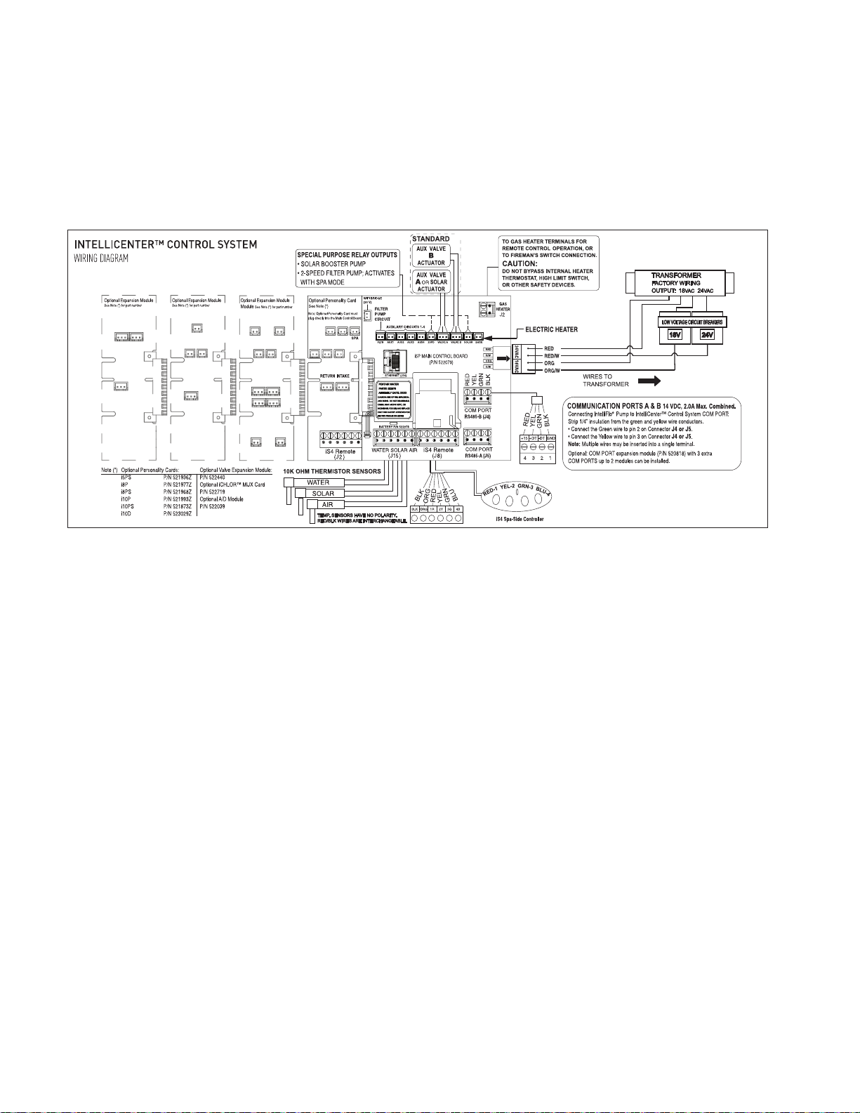
IntelliCenter® Control System Load Center and Power Center Wiring Diagram
• For InitelliCenter Control System wiring schematic, see page 60 and 61 (and inside front
door of Load Center and Power Center)
• For re-wiring the IntelliChlor
®
(SCG) transformer for 120V see page 37.
Rewiring the IntelliCenter Control System Transformer for 240VAC
The IntelliCenter® Control System Load Center/Power Center system transformer can be wired
for 120 VAC at 2AMP 50/60 Hz (factory installed) or 240 VAC at 1AMP 50/60 Hz. The system
transformer is pre-wired at the factory for 120 VAC service.
To rewire the system transformer for 240 VAC (see wiring diagram on next page):
BEFORE REMOVING THE HIGH VOLTAGE COVER PANEL FROM THE
LOAD CENTER OR POWER CENTER ENCLOSURE switch OFF the power at
the house main circuit breaker box.
1. SWITCH OFF AC POWER the Load Center and/or Power Center at the main circuit breakers.
2. Unlatch the front door latch and open the front door. Remove the two (2) retaining screws securing
the high voltage cover panel. Remove the HIGH VOLTAGE COVER PANEL from the enclosure.
3. Rewire the system transformer for 240 VAC as shown in the wiring diagram below.
4. Reinstall the High Voltage Panel: Insert the panel’s three tabs into the lower slots on the enclosure.
Secure the panel with the two (2) retaining screws.
5. Close the front door and secure with the latch.
Page 22
14
BREAKER SUBPANEL
AUX5AUX6
AUX7AUX8AUX9
*522612*
Wiring Diagram label for IntelliCenter Control System Upgrade Kit.
Rewiring the System Transformer for 240 VAC (Continued)
Loosen Outdoor Control Panel retaining screws
Front door
Remove two (2) retaining screws
securing High Voltage Cover Panel
Flip down the Outdoor Control
Panel to access circuit board and
low
voltage compartment
High Voltage Cover Panel
LOW VOLTAGE RACEWAY
(inside load center)
3 Tabs/Slots
IntelliCenter Control System Load Center (Front View)
Control System
transformer:
120VAC, 2.5A,
240VAC, 1.3A,
50/60 Hz
INPUT
INPUT
BONDING LUG
IntelliCenter® Control System Load Center Wiring Instructions
IntelliCenter Control System Installation Guide IntelliCenter Control System Installation Guide
Page 23
Accessing the IntelliCenter® Control System Circuit Boards
and Electronics
The IntelliCenter Control System Outdoor Control Panel is mounted on the front of the Load center
and Power Center. The system circuit boards and electronics are located behind the Outdoor
Control Panel. The circuit boards provides socket connectors for the auxiliary relays, valve
actuators, sensors, gas heater and related equipment. To access the circuit boards, fold down the
Outdoor Control Panel.
To access the main circuit board connectors:
1. Unlatch the front door spring latch and open the front door.
2. Remove the two retaining screws from the High Voltage Cover Panel. Remove the panel from the
enclosure.
3. Loosen the two retaining screws securing from the top edge of the Outdoor Control Panel. Fold
down the Outdoor Control Panel to access the circuit board sockets connectors for the electrical
connections.
4. Install the following:
• IntelliCenter Control System Load Center Relays, page 16
• Installing Valve Actuators, page 18
• IntelliValve® Valve Actuator, page 21
• Temperature Sensors, page 26-28
• Standard Gas Heater, page 29
• Connecting an IntelliFlo® Pump to the Load Center, page 30
• Pump and Heat Pump (UltraTemp®/Hybrid Heat Pump, page 31
• Connecting IntelliChlor® SCG, IntelliChem® Controller, page 32-38
5. After electrical connections have be completed, close the Outdoor Control Panel and tighten the
two retaining screws. Reinstall the High Voltage Panel: Insert the panel’s three tabs into the lower
slots on the enclosure. Secure the panel with the two (2) retaining screws. Close the front door and
secure with the latch.
15
Loosen Outdoor Control Panel
retaining screws
Front door
LOW VOLTAGE
RACEWAY
IntelliCenter Control System Load Center (Front view)
Flip down the Outdoor Control Panel to
access circuit board and low
voltage compartment
Remove two (2) retaining screws
securing High Voltage Cover Panel
High Voltage Cover Panel slots (3)
High Voltage Cover Panel Tabs (3)
(High Voltage Cover Panel removed)
Page 24

16
Connecting IntelliCenter® Control System Load Center Relays
For the IntelliCenter Control System (model i5PS) there are five high voltage relays pre-installed
in the Load Center (as shown on page 17); four auxiliary circuits (AUX) plus one relay for the filter
pump.
• Shared Equipment: Pool and spa combinations with shared filtration system – The Personality
Kit models are:
i5PS (P/N 521912) – Four auxiliary circuits plus filter pump operation. Five relays are included in the
Load Center.
i8PS (P/N 521913) – Seven auxiliary circuits plus filter pump operation. Three relays are included in
the personality kit and five in the Load Center.
i10PS (P/N 521914) – Nine auxiliary circuits plus filter pump operation. Five relays are included in
the personality kit and five in the Load Center.
• Dual Equipment: Pool and Spa with Dual Sets of Equipment – The IntelliCenter control system
i10D (P/N 521915) is designed to operate two sets of pool equipment. Each set of a equipment
(Pool or Spa) can control one temperature setting. This IntelliCenter control system Personality
Kit can control up to 10 pumps and/or lighting circuits, plus two heater circuits. The Personality Kit
includes, eight auxiliary circuits plus two filter pumps. Five relays are included in the personality kit
and five in the Load Center.
• Single Equipment: Pool Only or Spa Only – Single Equipment: Pool Only or Spa Only – This
system is designed to operate a single body of water (LO-TEMP and HI-TEMP). The Personality Kit
models are:
i5P (P/N 521909) – Four auxiliary circuits plus filter pump operation. Five relays are included in the
Load Center.
i8P (P/N 521910) – Seven auxiliary circuits plus filter pump operation. Three relays are included in
the personality kit and five in the Load Center.
i10D (P/N 521911) – Nine auxiliary circuits plus filter pump operation. Five relays are included in the
personality kit and five in the Load Center.
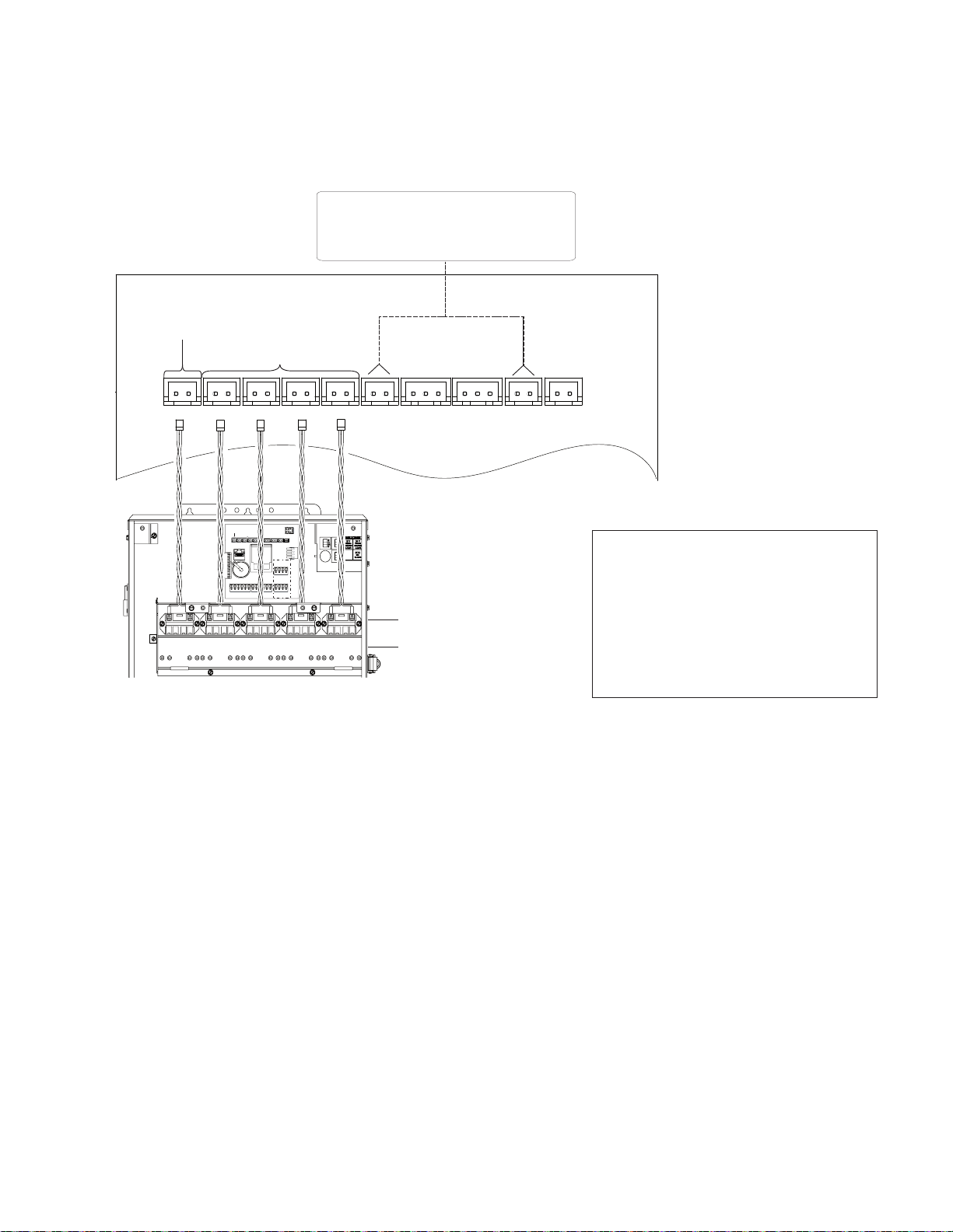
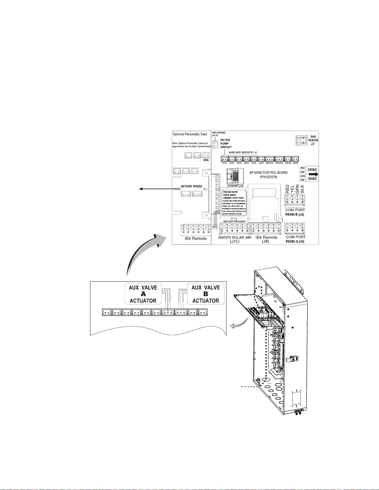
To connect the pre-installed relay cable plugs to the IntelliCenter Control System circuit board AUX
plugs:
• Route the power relay cable plugs up into the Low Voltage Compartment (as shown on page 17) to
the circuit board. Insert the plug into the two-pin sockets, beginning with FLTR PUMP, then AUX1,
AUX2, AUX3, and AUX4. For the two-pin socket locations, refer to the diagram shown below. For
IntelliCenter control System system wiring diagrams, see page 59-59.
Note: For optional relays; insert each optional auxiliary relay plug into the one of the two-pin
sockets, beginning with AUX5, AUX6, AUX7, AUX8 and AUX 9.
IntelliCenter Control System Installation Guide IntelliCenter Control System Installation Guide
Page 25
COM PORT
RS485-B (J16)
COM PORT
RS485-A (J15)
RS-485 COM PORT
TERMINALS
RED
YEL
GRN
BLK
J2
FLTR
AUX1 AUX2 AUX3 AUX4 2SPD VALVE A VALVE B SOLAR
ETHERNET
BATTERY
LHR2450
WATER SOLAR AIR
(J18)
iS4 Remote
(J17)
RED
R/W
ORG
O/W
AUXILARY CIRCUITS 1-4
FILTER PUMP
CIRCUIT
P/N 522061
GHTR
EHTR
ELECTRIC
HEATER
(J14)
FLTR
AUX1 AUX2 AUX3 AUX4 2SPD VALVE A VALVE B SOLAR
AUXILARY CIRCUITS 1-4
FILTER PUMP
CIRCUIT
SPECIAL PURPOSE RELAY OUTPUTS
• SOLAR BOOSTER PUMP
• 2-SPEED FILTER PUMP
EHTR
FLTR
AUX1 AUX2 AUX3 AUX4
PUMP
Connecting IntelliCenter® Control System Load Center Relays (Continued)
IntelliCenter Control System
Circuit Board (Model i5PS)
17
Note: Install the optional Two-Speed
Pump relay (P/N 520198) cable plug
into the 2SPD two-pin socket on the
High voltage auxiliary relay
locations
Optional high voltage relay
positions (2 SPD Relay
option)
IntelliCenter Control System Load Center relays AUX circuits connections (i5PS model)
Personality board (see page 36).
For installation and operation
information, refer to the
Two-Speed Relay User’s Guide
(P/N 520210).
Page 26
18
Installing V alve Actuators
The IntelliCenter® Control System can control multiple valve actuators. Two of the valve outputs
are dedicated to the pool/spa intake (INTAKE) and return (RETURN) valves. Valve A or Valve B
actuators are for general purpose use (solar, water-feature, in-floor cleaner, etc.). For IntelliCenter
Control System shared equipment systems there are two motorized valve actuators (CVA-24T, P/N
263045) provided in the kit.
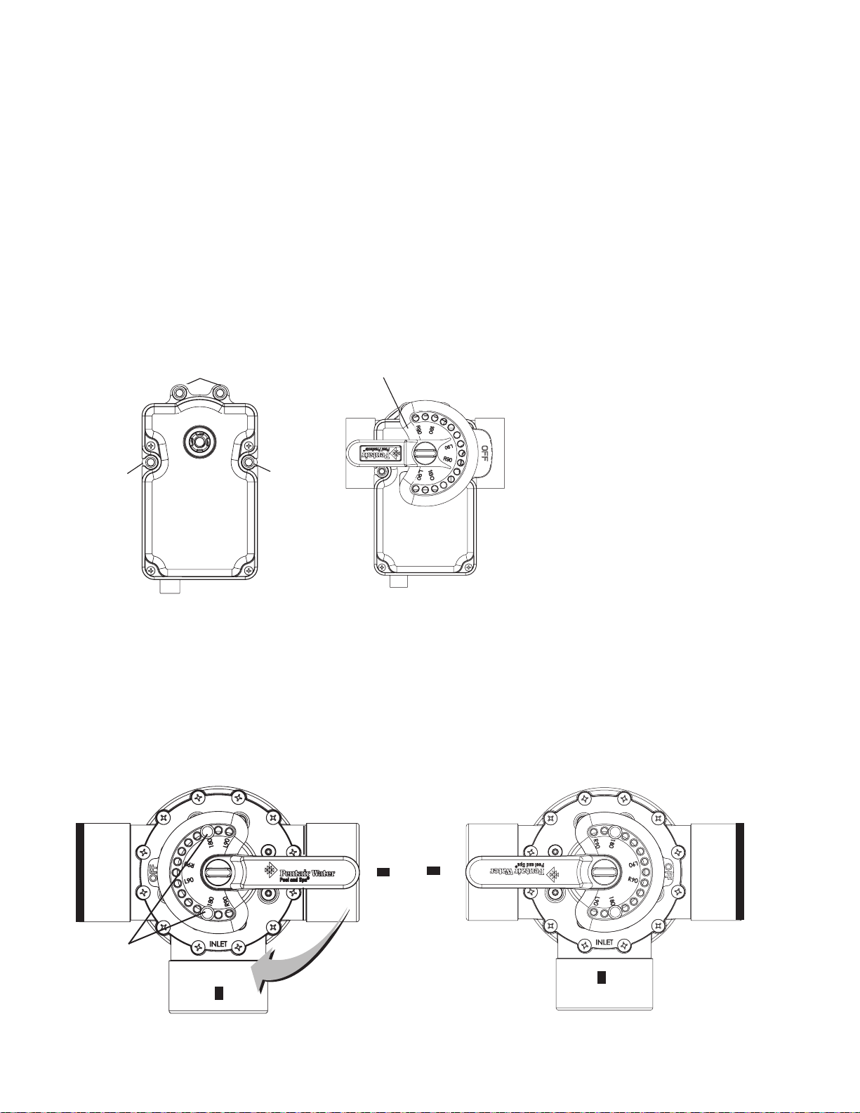
To install the valve actuator (two-way valve example shown):
1. Remove the valve knob, handle and the four screws, from the valve cover (indicated with arrows).
2. Align the splines of the actuator shaft over the shaft of the valve.
3. If the actuator is not aligned with the mounting holes on the valve cover, rotate the actuator (while
still attached to the valve) until the actuator is positioned correctly over the valve.
4. Secure the actuator with the screws provided. Only use self-tapping screws when required.
5. Mount the valve handle and knob onto the actuator.
Valve actuator
Adjusting the valve position
(3-way valve shown below)
If the valve rotates to the wrong position, adjust
the switch on the back of the actuator between
ON1 and ON2 positions. This will rotate the
valve to the correct position. The following
diagram shows the standard plumbing and
valve actuator position.
Screw
Screw
Screw
Valve Handle Operation: To reposition the valve handle: Rotate the handle to the desired “OFF” position.
The diverter valve handle OFF indicator, represents the current position of the valve’s internal diverter seal
which will stop the flow of water. The valve handle stop-pins determine the position of the diverter valve’s
internal seal to stop or allow water flow. Note: When a motorized valve actuator is installed, stop-pins are not
required.
Handle Stop-Pins Positions: The two movable stop-pins can be set to allow the valve handle’s position
to completely stop the flow of water, regulate a limited flow, or allow the maximum flow. To set the stoppins: Insert the stop-pins in the pin holes according to the corresponding “degree indicator” displayed
on top of the handle. The stop-pin positions can be set to 180°, L90° (left-side) and R90° (right side).
Repositioning of either stop-pins allows the handle to be set to any desired percentage of water flow.
PORT A
OFF
Stop Pins
Set for
180°
PORT C
OFF
PORT B (Common Port)
IntelliCenter Control System Installation Guide IntelliCenter Control System Installation Guide
Page 27
Installing V alve Actuators (Continued)
6. At the Load Center or Power Center, route the cable up through the 1” grommet and low voltage
raceway to the circuit board (as shown below).
19
7. Connect the Valve A actuator cable plug into the INTAKE (suction) 3-pin socket, and Valve B
®
actuator cable plug into the RETURN three-pin socket on the IntelliCenter
Control System
Personality circuit board. Excess cable can be coiled in the enclosure low voltage raceway
left side compartment (see page 7). Do not coil the conductor in Load Center upper low
voltage compartment. For valve actuator circuit board socket location see below. For plumbing
requirements, see Item 2 and 3 on page 69.
AUX 5 AUX 6
AUX 7 AUX 8 AUX 9
Valve RETURN and INTAKE
3-pin socket (i10PS model)
IntelliCenter Control System Main Circuit Board
(with i100PS optional expansion card shown)
AUX1 AUX2 AUX3 AUX4 2SPD VALVE A VALVE B SOLAR
FLTR
EHTR
IntelliCenter Control System Main Circuit Board
(Actuator A & B socket location)
To actuator: Three conductor cable
(Route up into low-voltage raceway to
main circuit board)
Page 28
20
AUX5 AUX6
AUX7 AUX8 AUX9
Installing V alve Actuators (Continued)
8. Optional Valve Module Expansion Boards: Using one Valve Module Expansion board (P/N
522038), six additional valve actuators (VALVE C, D, E, F, G, H) can be added to the system for a
total of 10 actuators. The expansion board attaches to the edge of the IntelliCenter Control System
circuit board. For installation and operation information, refer to the Valve Actuator Installation Guide
(P/N 270140).
IntelliCenter® Control System Circuit Board (Model i8PS shown)
IntelliCenter Control System Installation Guide IntelliCenter Control System Installation Guide
Page 29
Installing IntelliValve® V alve Actuator
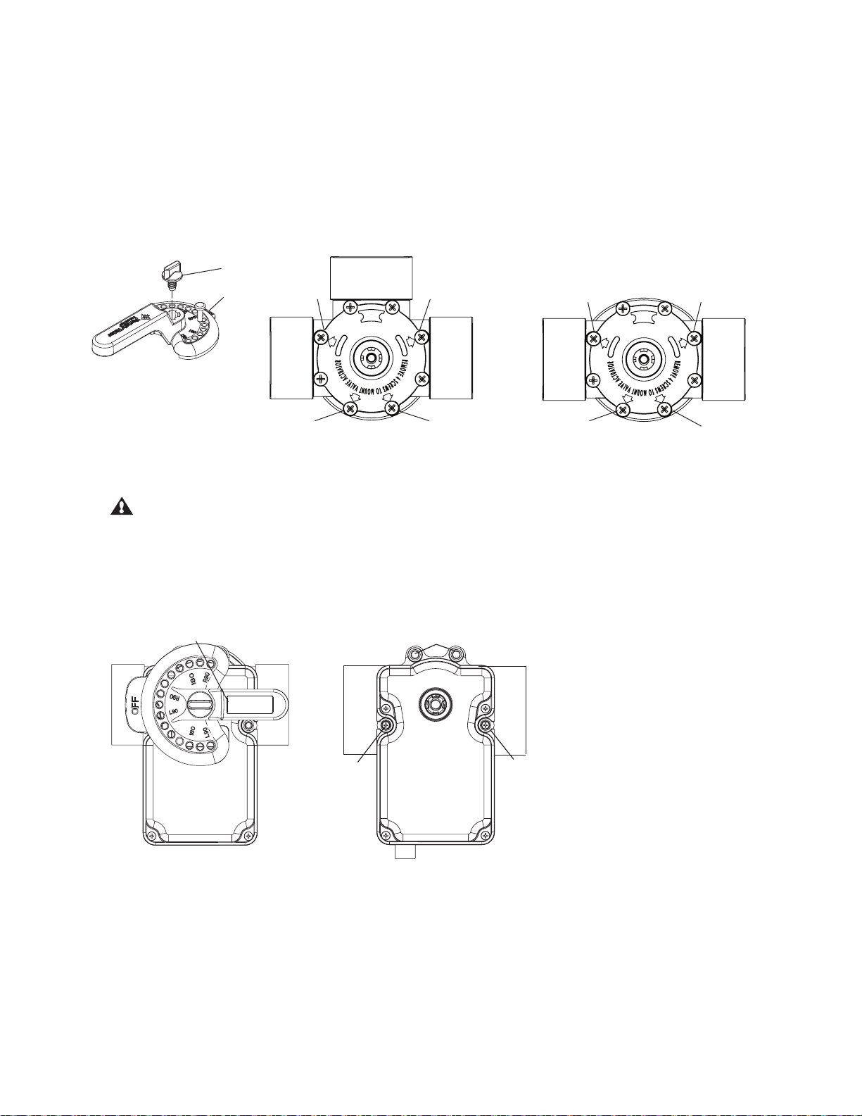
The IntelliValve Valve Actuator can be installed on a 2-way, 3-way or 3-way Y valve assembly.
Valve assembly without actuator:
• Unscrew and remove the diverter valve knob and handle. Remove the four screws from the
valve assembly top cover (embossed arrows indicate the screw locations as shown below).
Valve
knob
Valve
handle
Diverter Handle/Knob
screw
screw
screw
screw
21
screw
3-Way Valve Assembly
screw
screw
2-Way Valve Assembly
screw
Valve assembly with existing actuator:
1. CAUTION: Switch OFF the main system power at the circuit breakers.
2. Disconnect the valve actuator power cord from the control system.
3. Unscrew and remove the diverter valve knob and handle from the valve actuator.
4. Remove the four screws from the valve actuator assembly. Remove the actuator from the
valve, as shown below.
Remove handle
Remove
screw
Remove Screws
Remove
screw
Valve Assembly with Actuator
Page 30

22
Mount the IntelliValve® Valve Actuator onto the Valve:
1. Align the splines of the InitelliValve valve actuator shaft over the shaft of the valve. Note: The keyed
square spline notch (as shown below) indicates the position of the diverter. Note: End Point at 0
(OFF) is the default position of the IntelliValve Valve Actuator.
Note: There is silicone on the actuator assembly and spline. While mounting the IntelliValve valve
actuator be careful not to get silicone on the bottom of the IntelliValve assembly.
2. If the IntelliValve valve actuator does not align with the mounting holes on the valve cover, rotate
the actuator (while still attached to the valve) until the actuator manufacturers holes line up on the
valve.
Spline notch
arrow location
Arrow on actuator
indicates end
point 0 (OFF)
OUTLET
OFF
IntelliValve Actuator Spline Notch
(underside view)
Valve Assembly (top view) with
diverter at end point 0 OFF
INLET
3. Mount the IntelliValve valve actuator onto the valve assembly and secure it with the four 2¼ inch
mounting screws provided, as shown on the next page.
Note: DO NOT over tighten the mounting screws.
Mounting screw (x4)
20 ft. power cable plug (3-pin)
Connect to IntelliCenter
Control System circuit board
(Actuator A or B)
see page 25)
SPA RETURN
IntelliValve
Valve
Actuator
SPLINE
CAUTION: DO NOT
mount the IntelliValve
so that the suction or
return line of the pump
can be blocked. This
will cause permanent
pump damage.
INLET
IntelliValve Valve Actuator Mounted on a 3-Port Valve assembly
IntelliCenter Control System Installation Guide IntelliCenter Control System Installation Guide
POOL
RETURN
Page 31

Installing the IntelliValve® Valve Actuator (Continued)
20 ft. power cable plug (3-pin)
Connect to automation
control system circuit board (see
page 25)
INLET
IntelliValve
Valve
Actuator
SPLINE
OUTLET
IntelliValve Valve Actuator Mounted on a 2-Port Valve assembly
Operating the IntelliValve Valve Actuator (Basic Functions) - See IntelliValve User’s Guide
(P/N 522301) for more information.
Mode Button: Press the MODE button (press and release) to toggle between AUTO/OFF, SET and
SERVICE mode.
23
• AUTO Mode: Normal Operation
• OFF Mode: Disable IntelliValve Actuator function
• SET Mode: Set travel end points of valve diverter
• SERVICE Mode: Manual control - Temporary Settings
AUTO Mode (Green LED): The AUTO LED indicator is lit Green when the IntelliValve valve actuator is
in normal operation.
• The actuator will move the diverter via the pool and spa automation control system.
• Only the current diverter position LED is lit while the diverter is in motion.
• Reversing Home Position from one end point to the other can only be done in AUTO MODE.
OFF Mode:
• (Red LED): OFF mode can only be enabled while in AUTO or SERVICE mode.
• Press and hold SAVE until AUTO LED turns Red.
• All other buttons are disabled during OFF mode.
• To return to ON, press and hold SAVE again until AUTO LED turns Green.
Position 0
(Default
diverter
position)
AUTO/OFF
(Green LED)
AUTO Mode
AUTO/
OFF
(Red LED)
OFF Mode
Page 32

24
Connecting Power to the IntelliValve® V alve Actuator
After the IntelliValve Valve Actuator is mounted on to each of the valve assemblies, connect each
IntelliValve Valve Actuator 24 V power cable to the 3-pin power sockets on the automation control
system circuit board. The IntelliCenter
valve actuators via a RS-485 four conductor connection. for more information, see the IntelliCenter®
Control Panel User’s Guide (P/N 522990). Two of the standard valve outputs are dedicated to the
pool/spa INTAKE and RETURN valves. Valve A or Valve B actuators are for general purpose use
(solar, water-feature, in-floor cleaner, etc.).
Note: This de vice must be installed by a licensed or certified electrician or a qualified pool professional
in accordance with the National Electrical Code (NEC), NFPA 70 or the Canadian Electrical Code
(CEC), CSA C22.1.
BEFORE INST ALLA TION OR SER VICING THE INTELLIVALVE
Always disconnect power at the cir cuit breaker before servicing. Failure to do
so could result in death or serious injury to service person, pool users or
others due to electric shock.
To connect the IntelliValve Actuator Power Cable:
Control System can control up to four IntelliValve automatic
®
VAL VE ACTUA TOR
1. At the Load Center route the 20 ft. IntelliValve Valve Actuator power cable up through the Load
Center 1” grommet and low voltage raceway to the IntelliCenter main circuit board (as shown on
page 3).
2. Connect the Valve A actuator cable plug into the INTAKE (suction) 3-pin socket, and Valve B
actuator cable plug into the RETURN three-pin socket on the IntelliCenter Control System circuit
board. Excess cable can be coiled in the enclosure low voltage raceway left side compartment (see
page 7). Do not coil the conductor in Load Center upper low voltage compartment. See IntelliValve
Valve Actuator circuit board socket location below. For plumbing requirements, see Item 2 and 3 on
page 54.
Note: IntelliCenter Control System Optional Valve Module Expansion Board: Using a Valve
Module Expansion board (P/N 522038), three additional valve actuators (VALVE C, D and E) can
be added to the system. The expansion board attaches to the edge of the IntelliCenter main circuit
board. For installation and operation information, refer to the Valve Actuator Installation Guide (P/N
520294).
Test the IntelliValve Valve Actuator: Switch on power to the IntelliCenter Control System at the
circuit breaker and verify that the IntelliValve valve actuator is operating correctly.
AUX 5 AUX 6
AUX 7 AUX 8 AUX 9
Valve RETURN and INTAKE
3-pin socket (i5PS model)
Model i5PS IntelliCenter Control System Main Circuit Board
IntelliCenter Control System Installation Guide IntelliCenter Control System Installation Guide
Page 33

FLTR
AUX1 AUX2 AUX3 AUX4 2SPD VALVE A VALVE B SOLAR
EHTR
Connecting Power to the IntelliValve® V alve Actuator
AUTO
OFF
SERVICE
MODE
0
24
2
4
6
8
101214
16
18
20
22
LR
SET
CCW/CW
SAVE
X
CW
X
CCW
i5PS IntelliCenter Control System Main Circuit Board
(Actuator A & B socket location)
RS-485 COM Port
(J4/J5)
25
Optional Expansion
Board (P/N 520818)
Standard Valv e Actuator
Connecting a Standard Actuator and IntelliValve Valve Actuator: Connect the three conductor cable connector from
the actuator to Valve A or Valve B three-pin socket on the IntelliCenter Control System Personality circuit board. Route
the cable into low-voltage raceway to the IntelliCenter Control System main circuit board.
RS-485 COM Port (J4/J5) Connection for Automation Control: Use the GREEN and YELLOW conductors on the
IntelliValve actuator (remove the tie wraps from the wires). Connect the Green/Yellow conductors to the Green and
Yellow screw terminals on RS-485 COM Port (J4 or J5) located on the Personality board. Route the IntelliValve cable into
low-voltage raceway to the Expansion board mounted on the back of the Load Center.
Note: If there are no RS-485 COM Ports available, install the optional Expansion Board, see below.
Note: Optional Expansion Board (P/N 520818): Use the GREEN and YELLOW conductors on the IntelliValve
actuator (remove the tie wraps from the wires). Connect the Green/Yellow conductors to one of the 2-pin Green and
Yellow screw terminals located on the Expansion board. Route the IntelliValve cable into low-voltage raceway to the
Expansion board mounted on the back of the Load Center.
IntelliValve Valve Actuator
IntelliValve conductors
(Green/Yellow)
Optional Expansion Board
(Located in the Load Center)
Page 34

26
AIR
SOLAR
WATER
AIR
SOLAR
WATER
(J15)
Installing Water T emperature Sensor
To install the water sensor:
1. Select a convenient location to mount the water sensor in the plumbing system between the filter
pump and filter. Drill a 3/8” diameter hole in one side of the pipe,
2. Insert tip of sensor into the hole. Use the band clamp to secure the sensor to the pipe. Tighten the
clamp just enough so that the o-ring begins to flatten. Do not overtighten
3. Fasten the cable to the plumbing with cable ties.
4. Run 22 AWG two-conductor cable (included in kit) between the sensor and the Load Center and
Power Center. Route the cable up through the low voltage raceway to the circuit board, as shown
below.
5. Cut off the excess conductor and the strip conductors ¼ inch.
6. Insert the conductors into the WATER SENSOR screw terminals (J15) on the main IntelliCenter
Control System circuit board. For sensor circuit board screw terminal location see page 26.
Installing Ambient Air Temperature Sensor (for freeze protection)
To install the air sensor:
1. Mount the sensor in the open air, in a shaded area, away from air conditioners. During the winter
months, to avoid freeze damage to pool and spa equipment, mount the air sensor in a shaded
area to assure proper temperature readings. The Home screen displays the current ambient air
temperature.
Run 22 AWG two-conductor cable (included in kit) between the sensor and the Load Center or
Power Center. Route the cable up through the low voltage raceway to the circuit board (as shown
below.
3. Cut off the excess conductor and the strip conductors ¼ inch.
®
4. Insert the conductors into the AIR screw terminals (J15) on the IntelliCenter
Control System main
circuit board. For sensor circuit board screw terminal location.
IntelliCenter Control System Circuit Board
(Air, Water and Solar sensor location)
To valve actuator
IntelliCenter Control System Installation Guide IntelliCenter Control System Installation Guide
Page 35

Installing the Solar Temperature Sensor (Optional)
Solar Panels Installation
• Be sure the maximum flow of water through the solar panels, a solar booster pump should be added
if panels are installed at a very high elevation.
• It is recommended that the solar panels are mounted in a way that gravity will allow draining
whenever the filter pump is not on.
• For systems with glazed panels, damage can occur from overheating if the filter pump is still running
after the solar has turned off. To enable glazed panels to automatically drain whenever the solar
turns off (even if the filter pump is still running), a 1/2” motorized solar drain valve should be plumbed
from the solar feed line, through a check valve, to a zero psi point (such as pool fill line or jet air
intake).
Solar Temperature Sensor Installation (as shown on page 26)
Run a two-conductor cable between the sensor and the IntelliCenter® Control System circuit board
in the Load Center.
To install the solar sensor:
27
CAUTION! DO NOT DRILL HOLE AND CLAMP SENSOR INTO SOLAR PIPE.
1 Mount the sensor on a flat surface, with the same exposure to sun as the solar collectors (next to
the collectors is recommended) or any sunny location. Do not let the sensor touch the panels. For
glazed panels, install the sensor between collector and glazing.
2 If necessary, splice a two-conductor extension conductor to the sensor. Run two-conductor cable
between the sensor and the enclosure. Use waterproof connectors to connect the sensor to the
cable. Use twisted pair 20 AWG outdoor rated sensor wiring and be sure the conductor connections
are protected from the environment. Use shielded cable for long runs or runs near other electrical
wiring.
3. Cut off the excess conductor and the strip back conductors ¼ inch.
4. Insert the conductors into the SOLAR SENSOR screw terminals (J15) on IntelliCenter Control
System circuit board. For sensor circuit board screw terminal location see page 26.
Page 36

28
Temp
(
o
C )
Temp
( oF )
Resistance
(Ω)
Temp
( oC )
Temp
( oF )
Resistance
(Ω)
Temp
( oC )
Temp
( oF )
Resistance
(Ω)
-50 -58 669,500 25 77 10,000 95 203 787
-45 -49 471,500 27 80 9,298 96 205 761
-40 -40 336,200 29 85 8,250 99 210 701
-35 -31 242,500 30 86 8,056 100 212 679
-37 -35 280,100 32 90 7,331 102 215 646
-34 -30 234,100 35 95 6,530 104 220 596
-32 -25 196,300 38 100 5,826 105 221 587
-29 -20 165,100 40 104 5,326 107 225 552
-30 -22 176,800 41 105 5,209 110 230 510
-26 -15 139,300 43 110 4,663 113 235 472
-25 -13 130,300 45 113 4,367 115 239 444
-23 -10 118,000 46 115 4,182 116 240 438
-21 -5 100,200 49 120 3,757 120 248 389
-20 -4 97,000 50 122 3,602 125 257 341
-18 0 85,350 52 125 3,381 130 266 300
-15 5 72,910 54 130 3,047 135 275 264
-12 10 62,480 55 131 2,985 140 284 234
-9 15 53,640 57 135 2,750 145 293 208
-10 14 55,300 60 140 2,487 150 302 185
-7 20 46,230 63 145 2,251
-5 23 42,300 65 149 2,083
-4 25 39,910 66 150 2,041
-1 30 34,560 68 155 1,854
0 32 32,600 70 158 1,752
2 35 30,000 71 160 1,686
5 40 26,100 74 165 1,535
5 41 25,400 75 167 1,480
7 45 22,760 77 170 1,400
10 50 19,900 79 175 1,278
13 55 17,440 80 176 1,256
15 59 15,700 82 180 1,168
16 60 15,310 85 185 1,071
18 65 13,480 88 190 980
20 68 12,500 90 194 916
21 70 11,880 91 195 900
24 75 10,500 93 200 827
Temperature vs. Resistance Data
The IntelliCenter® Control System use 10k Ohm thermistor sensors. When the solar sensor is
disconnected from the control system, the sensor will read 10k Ohm at 77º F (25ºC). Refer to
the following table for the resistance at other temperatures. An accurate reading should give a
temperature setting that is accurate to ±0.2º C from 0 to 70 º C.
IntelliCenter Control System Installation Guide IntelliCenter Control System Installation Guide
Page 37

Connecting a Standard Gas Heater to the Load Center
J2
FLTR
AUX1 AUX2 AUX3 AUX4 2SPD VALVE A VALVE B SOLAR
GHTR
EHTR
ELECTRIC
HEATER
GAS HEATER
(two-screw terminals (J2)
The IntelliCenter® Control System heater control uses low voltage dry contacts that can be connected to
most gas heaters or heat pumps with 24 VAC control circuits. The following connection instructions are for
gas heaters and heat pumps with low voltage thermostats. To connect the heater thermostat cable plug to
the IntelliCenter Control System circuit board:
1. Switch OFF power to the heater.
CAUTION IMPORTANT: DO NOT disconnect or conductor around the thermostat, pressure
switch, high limit switch, or other safety devices.
2. Remove the factory installed jumper from the heater’s Fireman’s Switch connector. At the
heater, connect the conductors in accordance with heater manufacturer’s instructions. For older
heaters without instructions for remote operation, connect the conductors to the Fireman’s switch
connections in series with the thermostat, pressure switch, and other safety switches.
3. Run a two-conductor cable from the heater Fireman’s Switch connector through the low voltage
raceway to the Load Center or Power Center circuit board, as shown below.
NOTE: Use 221° F (105° C) temperature rated conductor for connection to the heater. When
connecting conductors inside the heater, be cautious of HOT internal parts of the heater. Refer to
the minimum temperature rating for conductors recommended by the manufacturer. See the heater
owners manual for details.
29
4. Strip back the conductors ¼ in.
5. Insert the conductors into the GAS HEATER two-screw terminals (J2) on the motherboard. For
heater circuit board screw terminal location see below.
CAUTION: Be sure that the conductors from the heater to the IntelliCenter Control System Load
Center are not near or touching any line voltage conductors in the heater. Failure to follow these
instructions may cause the heater to malfunction.
6. Set the Power (Thermostat Select) switch to either Pool or Spa.
7. Set the heater’s Pool and Spa thermostats to their maximum position.
IntelliCenter Control System Circuit Board
(Gas heater connection terminal location)
To gas heater
IntelliCenter Control System Circuit Board
(Heater connection terminal (J2) location)
Page 38

30
Connecting an IntelliFlo® Pump to the Load Center
A 50 ft 22 AWG four conductor low voltage RS-232 communication cable is provided with IntelliFlo
pump. The IntelliCenter® Control System filter pump output is rated at 120 VAC, 15 AMP maximum.
NOTE: Check the electrical rating marked on the pump motor before connecting it to the system.
To connect the IntelliFlo pump communication cable to the Load Center:
1. Switch AC power OFF to the Load Center at the main house circuit breakers.
2. Run the communication cable from the pump to the Load Center or Power Center.
3. Insert the cable conductors into the one of the plastic grommet fittings, located on the lower left side
of the enclosure and pull the cable up through the low voltage to the circuit board, as shown below.
4. Strip back the outer jacket four inches. Strip back each conductor a ¼-inch.
5. IntelliCenter Control System COM Port (J4 or J5): Insert the conductors into the COM Port
screw terminals located on the top of the IntelliCenter Control System circuit board (see diagram
below). Secure the conductors with the screws. For wiring details, refer to the pin configuration
shown below. Note: Multiple conductors may be inserted into a single screw terminal.
Connecting IntelliFlo® Pump to IntelliCenter™ Control System COM PORT:
Strip 1/4” insulation from the green and yellow wire conductors.
• Connect the Green wire to pin 2 on Connector J4 or J5.
• Connect the Yellow wire to pin 3 on Connector J4 or J5.
Note: Multiple wires may be inserted into a single terminal.
Optional: COM PORT expansion module (P/N 520818) with 3 extra
COM PORTS up to 2 modules can be installed.
14 VDC, 2.0A Max. Combined.
IntelliCenter Control System
COM PORT (J5 or J6)
Screw Terminal
COM Port
screw
terminal
connector
2 (GRN) GREEN (Pin 6)
Note: COM PORT A& B
14 VDC, 2.0A Max.
Combined
+15 +DT -DT GND
4 3 2 1
TO HEATER
To pump
CONTROL PANEL
RS-485 COM PORT
IntelliFlo Pump
(2-wire cable)
3 (YEL) YELLOW (Pin 7)
IntelliFlo pump communication cable pin out
IntelliCenter Control System Installation Guide IntelliCenter Control System Installation Guide
Page 39

Connecting a Pentair UltraTemp® and Hybrid™ Heat Pump to the Load Center
Be sure to check the UltraTemp Heat Pump terminal block conductor colors and pinouts (located on
the back of the Auto Set board) before connecting it to the Load Center COM port. The See the wiring
table below for the pin configuration.
IMPORTANT: On the UltraTemp Heat Pump AutoSet circuit board ONLY CONNECT PIN 3 (YELLOW) and
PIN 2 (GREEN) to the IntelliCenter Control System COM port pins YELLOW and GREEN respectively. Do
not connect pin 1 or pin 4 on the AutoSet board or the COM port. These pins are not used.
Wiring Description
31
COM Port Wire Color (J4 / J5) Description
PIN 4 (RED) (DO NOT USE) +15 VDC
PIN 3 (YELLOW) + DATA PIN 3 (YELLOW)
PIN 2 (GREEN) - DATA PIN 2 (GREEN)
UltraTemp Heat Pump/UltraTemp and Hybrid Heat Pump
(J1) Pin Number and Wire Color
PIN 4 (DO NOT USE)
Connecting a Pentair Hybrid Heat Pump to the Load Center
Be sure to check the Hybrid Heat Pump terminal block conductor colors and pinouts before
connecting it to the Load Center COM port. The See the Hybrid Heat Pump wiring table below for the
pin configuration.
IMPORTANT: On the Hybrid Heat Pump circuit board (J1) ONLY CONNECT PIN 3 (YELLOW) and PIN 2
(GREEN) to the IntelliCenter® Control System COM port pins YELLOW and GREEN respectively. Do not
connect pin 1 or pin 4 on the AutoSet board or the COM port. These pins are not used.
Wiring Description
1/4 in. “Spade”
Connectors
Page 40

32
Connecting the IntelliChlor® SCG Power Cord to the Enclosure Socket
The IntelliChlor SCG cell power cord is connected to the socket on the bottom of the IntelliCenter®
Control System Load Center (shown below) and Power Center enclosure.
BEFORE REMOVING THE HIGH VOLTAGE COVER PANEL FROM THE LOAD
CENTER OR POWER CENTER, switch the main power OFF into the home at the
main circuit breaker box and also switch OFF the main power to the Load Center/
Power Center.
TO AVOID AN ELECTRICAL HAZARD AND EQUIPMENT DAMAGE TO THE ENCLOSURE AND
INTELLICHLOR SCG CELL: FIRST DISCONNECT AC POWER TO THE ENCLOSURE BEFORE
CONNECTING THE INTELLICHLOR SCG CELL POWER CABLE TO THE ENCLOSURE SOCKET.
To connect the IntelliChlor SCG power cord to the Load Center or Power Center:
1. Switch OFF AC power to the enclosure at the main house panel circuit breaker.
2. Unlatch the front door latch and open the front door. Remove the two retaining screws from the High
Voltage Cover Panel and remove the panel.
3. Loosen the two retaining screws securing from the top edge of the Outdoor Control Panel. Fold
down the Outdoor Control Panel to access the circuit board sockets connectors for the electrical
connections.
4. Align the four pins of the IntelliChlor cell power cord connector with the socket on the bottom of the
enclosure and insert the cord connector into the socket.
5. Rotate the socket nut until it locks the connector in place. Do not over tighten the nut (hand tighten
only).
®
6. Proceed to “Connecting IntelliChlor
SCG COM Port Cable” on next page.
Loosen Outdoor Control
Panel retaining screws
Front door
LOW VOLTAGE
RACEWAY
Sots (3)
Connector
socket nut
Flip down the Outdoor Control Panel to
access circuit board and low
voltage compartment
Remove two (2) retaining screws
securing High Voltage Cover Panel
High Voltage Cover Panel Tabs (3)
IntelliChlor
SCG Power
Cable
Connector
To IntelliChlor SCG cell
IntelliCenter Control System
IntelliCenter Control System Installation Guide IntelliCenter Control System Installation Guide
(Load Center with IntelliChlor SCG option)
Page 41

33
Connecting the IntelliChlor
®
SCG Communication Cable to a COM Port
The IntelliChlor SCG communicates from the IntelliCenter® Control System circuit board to the
IntelliChlor SCG circuit board via an RS-485 communications four conductor, 22 AWG or larger
cable. This cable (provided in kit) connects to both the IntelliChlor (SCG) circuit board COM port
terminal and the IntelliCenter Control System circuit board COM port.
TO AVOID AN ELECTRICAL HAZARD AND EQUIPMENT DAMAGE TO THE ENCLOSURE
AND INTELLICHLOR CELL: FIRST DISCONNECT AC POWER TO THE ENCLOSURE BEFORE
CONNECTING THE INTELLICHLOR COMMUNICATION CABLE.
To connect the IntelliChlor SCG COM port cable (see page 34 for connector pinouts/color match):
7. First, connect the cable to COM port J4 on the IntelliChlor SCG circuit board, then connect
the other end of the cable to the IntelliCenter Control System COM port (J4 of J5) screw terminal
located on the IntelliCenter Control System circuit board (see screw terminal location below). Note:
Any of the three COM ports on the IntelliCenter Control System circuit board can be used for the
IntelliChlor SCG communications cable.
8. After electrical connections have be completed. close the Outdoor Control Panel and tighten the
two retaining screws. Reinstall the High Voltage Panel: Insert the panel’s three tabs into the lower
slots on the enclosure. Secure the panel with the two retaining screws. Close the front door and
secure with the latch. See page 34.
9. Switch ON AC POWER to the load center at the circuit breaker.
IntelliChlor SCG circuit board
COM Port J4
AUX 5 AUX 6
AUX 7 AUX 8 AUX 9
COM Port J4
IntelliCenter Control System main circuit board
(with i10PS optional expansion card shown)
IntelliCenter Control System Load Center/Power Center
(with IntelliChlor SCG option) (Control Panel not shown)
Page 42

34
Connecting a Salt Chlorine Generator to the Load Center or Power Center
Be sure to check each conductor color between the salt chlorine generator and the IntelliCenter
Control System Load Center (with SCG option) as shown in the following wiring tables.
Commonly used salt chlorine generator wiring is shown below. However, but you should still verify
with the manufacturers documentation. Failure to connect the salt chlorine generator properly can
permanently damage the IntelliCenter Control System and/or the salt chlorine generator.
Wiring Description
®
(IntelliChlor
SCG Circuit board COM Port to IntelliCenter Control System COM Port J4/J5)
®
SCG COM Port wiring
color connection
RED +15 VDC RED
YELLOW + DATA YELLOW
GREEN - DATA GREEN
BLACK GROUND BLACK
Description
From IntelliChlor SCG Power
Center COM Port #1
Wiring Description (Hayward® or Jandy® Load Center COM Port)
Hayward® or Jandy®
Load Center COM port
wiring color connection
RED +15 VDC RED
YELLOW + DATA BLACK
GREEN - DATA YELLOW
BLACK GROUND GREEN
Description
IntelliChlor Salt Chlorine
Generator
Wiring the IntelliChem® Controller to the Load Center
Be sure to check each conductor color between IntelliChem Controller and the IntelliCenter Control
System Load Center and/or Power Center as shown in the following wiring table.
Wiring Description (IntelliChem COM Port to IntelliCenter Control System COM Port)
IntelliChem Controller
COM Port (J7) wiring
color connection
RED (DO NOT USE) +15 VDC RED (DO NOT USE)
YELLOW + DATA YELLOW
GREEN - DATA GREEN
BLACK GROUND BLACK
IntelliCenter Control System Installation Guide IntelliCenter Control System Installation Guide
Description
From IntelliCenter Control
System COM Port (J4 / J5)
Page 43

35
Wiring the IntelliChlor
IMPORTANT! IntelliChlor SCG AC transformer wiring Instructions: When using the IntelliCenter®
Control System with the IntelliChlor SCG option, be sure the IntelliChlor SCG AC transformer
conductors are connected to the LOAD SIDE OF THE FILTER PUMP RELAY located in the load center
(see page 36). This ensures that the IntelliChlor SCG cell produces chlorine only when the pool/spa
filter pump is on.
®
SCG Transformer to Load Center Filter Pump Relay
BEFORE REMOVING THE HIGH VOLTAGE COVER PANEL FROM THE LOAD
CENTER OR POWER CENTER, switch OFF the power at the house main circuit
breaker box.
TO AVOID AN ELECTRICAL HAZARD AND EQUIPMENT DAMAGE TO THE ENCLOSURE
AND INTELLICHLOR CELL: FIRST DISCONNECT AC POWER TO THE ENCLOSURE BEFORE
CONNECTING THE INTELLICHLOR SCG COMMUNICATION CABLE.
To connect the IntelliChlor (SCG) transformer conductor to the main filter pump relay:
1. Switch OFF AC power to the enclosure at the main house panel circuit breaker.
2. Unlatch the front door latch and open the front door. Remove the two retaining screws from the High
Voltage Cover Panel and remove the panel.
3. Loosen the two retaining screws securing from the top edge of the Outdoor Control Panel. Fold
down the Outdoor Control Panel to access the circuit board sockets connectors for the electrical
connections. Remove the panel from the enclosure, as shown below.
4. Locate the FILTER PUMP RELAY. Connect the IntelliChlor SCG transformer conductors to the
LOAD SIDE of the relay as shown on the next page.
5. After electrical connections have be completed, reinstall the High Voltage Panel: Insert the panel’s
three tabs into the lower slots on the enclosure. Secure the panel with the two (2) retaining screws.
Close the front door and secure with the latch.
6. SWITCH ON AC power to the load center.
Loosen two (2) retaining
screws to remove HIGH
VOLTAGE COVER
PANEL
CONNECT SCG TRANSFORMER
TO FILTER PUMP RELAY
HIGH VOLTAGE
COVER PANEL
CONNECT SCG TRANSFORMER
TO FILTER PUMP RELAY
IntelliCenter® Control System
Load Center (with SCG option)
IntelliCenter Control System
Power Center (with SCG option)
Page 44

36
TO FLTR (FILTER PUMP) SOCKET
(ON INTELLCENTER™ CONTROL SYSTEM
CIRCUIT BOARD)
FILTER PUMP RELAY
(IN POWER CENTER)
LOAD SIDE (VOLTAGE)
LOAD SIDE
LOAD SIDE
LINE SIDE
Source voltage:
120 VAC or 240 VAC
to circuit breaker sub-panel
IntelliChlor® SCG Transformer
IntelliCenter™ Control System Load Center
LOAD SIDE (VOLTAGE)
IntelliCenter™ Control
System Circuit Board
FILTER PUMP
CIRCUIT
WhisperFlo® 2-Speed Pump AC power
cord connect to LOAD SIDE of Filter
Relay (wired for 120 or 240 VAC)
TO AUX SOCKET ON
CIRCUIT BOARD
TO PUMP SOCKET
ON CIRCUIT BOARD
120 VAC
120 VAC
2-SPEED PUMP OPTION
TO PUMP MOTOR TERMINALS
Connect IntelliFlo® Pump AC power
cord to 240 Volt 20 AMP direct circuit
breaker in IntelliCenter load center or
separate sub-panel.
IntelliFlo
®
Pump communication cable
connects to RS-485 COM port on
IntelliCenter load center circuit board.
Pool Features Lights
Air Temp 65° F
ScheduleUsageChemistry Status
2 3
84°
78°
8:00 A.M.
LINE SIDE
AUX5
Wiring the IntelliChlor
®
SCG Transformer to Load Center Filter Pump Relay
IntelliCenter Control System Installation Guide IntelliCenter Control System Installation Guide
IntelliCenter® Control System Load Center - IntelliChlor® SCG Connection Diagram
Page 45

Rewiring the IntelliChlor® SCG Transformer for 120VAC
The IntelliChlor SCG power supply transformer is located in the IntelliCenter® Load Center and
Power Center can be wired for 240 VAC at 1AMP (factory installed) or 120 VAC at 2AMP 50/60 Hz.
The IntelliChlor SCG transformer is pre-wired at the factory for 240 VAC service.
To rewire the IntelliChlor SCG transformer and for 120 VAC:
BEFORE REMOVING THE HIGH VOLTAGE COVER PANEL FROM THE
LOAD CENTER OR POWER CENTER ENCLOSURE switch OFF the power at
the house main circuit breaker box.
1. Switch OFF AC power to the enclosure at the main house panel circuit breaker.
2. Unlatch the front door latch and open the front door. Remove the two retaining screws from the High
Voltage Cover Panel and remove the panel.
3. Loosen the two retaining screws securing from the top edge of the Outdoor Control Panel. Fold
down the Outdoor Control Panel to access the circuit board sockets connectors for the electrical
connections. Remove the panel from the enclosure, as shown below.
4. Rewire the SCG transformer for 120 VAC as shown in the wiring diagram on next page.
5. Reinstall the High Voltage Panel: Insert the panel’s three tabs into the lower slots on the enclosure.
Secure the panel with the two (2) retaining screws. Close the front door and secure with the latch.
37
6. SWITCH ON AC power to the load center.
Loosen Outdoor Control Panel
retaining screws
Front door
LOW VOLTAGE
RACEWAY
High Voltage Cover Panel slots (3)
Flip down the Outdoor Control Panel to
access circuit board and low
voltage compartment
Remove two (2) retaining screws
securing High Voltage Cover Panel
High Voltage Cover Panel Tabs (3)
Page 46
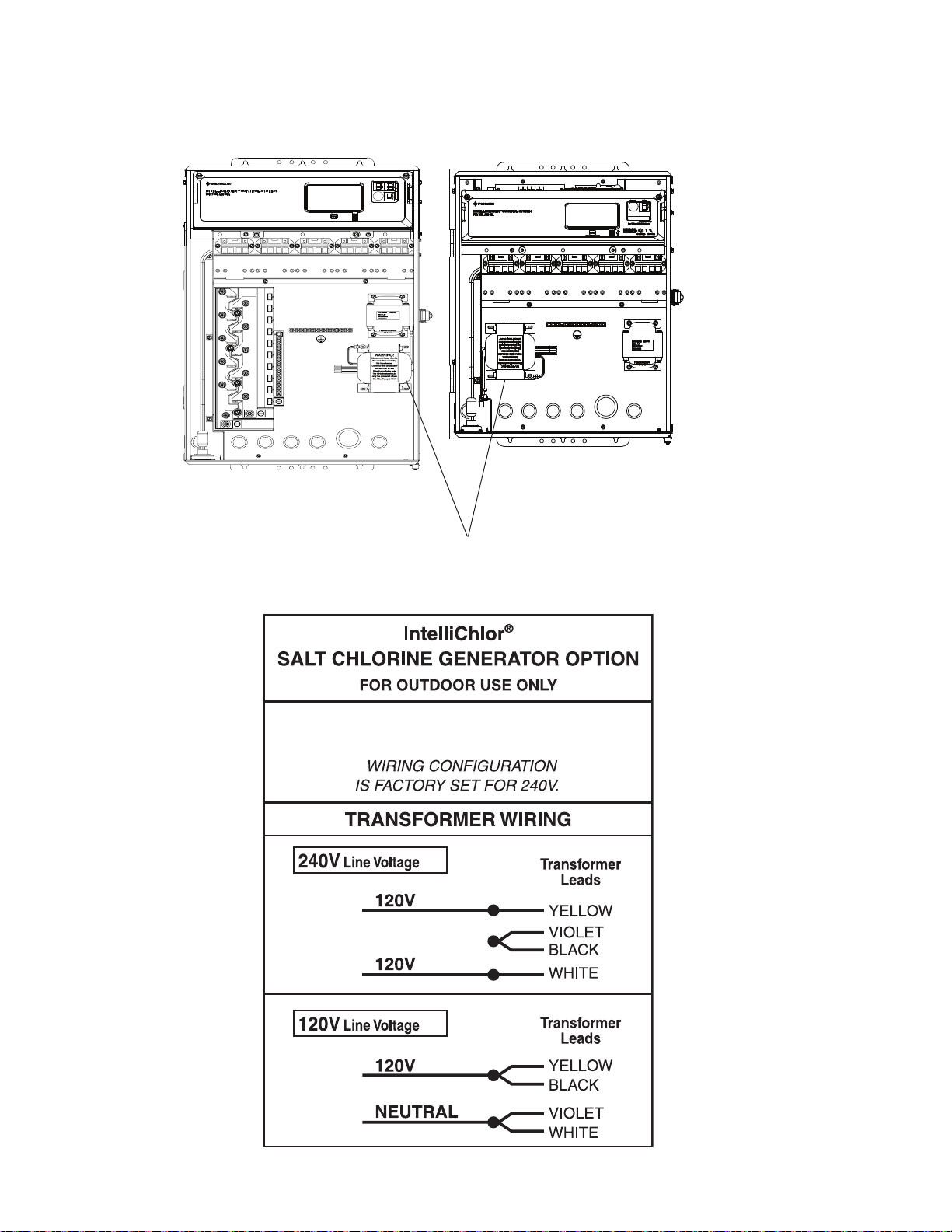
38
INPUT: 120 VAC AT 2.5 A, 50/60 Hz
240 VAC AT 1.3 A, 50/60 Hz
Rewiring the IntelliChlor® SCG Transformer for 120VAC (Continued)
IntelliCenter Control
IntelliCenter Control System
Load Center (with SCG option)
System Power Center
(with SCG option)
IntelliChlor (SCG)
Transformer
IntelliCenter Control System Installation Guide IntelliCenter Control System Installation Guide
Page 47
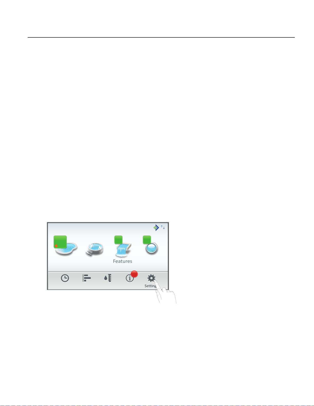
Section 2
Pool Spa Features Lights
Air Temp 77°F
Schedule Usage Chemistry Status
3
3 3
84°
78°
°
08:00 am
Freeze Protect Active
IntelliCenter® Control System Start Up
System Start-Up
Note: The following information describes how to configure the IntelliCenter Control System using
the step-by-step Setup Wizard. For more detailed information refer to the IntelliCenter® Control
System User’s Guide (P/N 522990).
Power On the Load Center and/or Power Center
1. After all the necessary pool and spa equipment has been connected to the Load Center/Power
Center, replace and secure the High Voltage Panel on to the front of the Load Center and/or Power
Center.
2. Switch on the main circuit breakers to apply power to the Load Center and/or Power Center.
Start the Setup Wizard
39
1. The IntelliCenter® Control System Outdoor Control Panel will be powered on.
2. From the Home screen tap Settings > Advanced system Configuration > Wizard.
3. Follow the screen prompts to configure the system. When finished save the system configuration.
The system is now ready for operations. For more information refer to the IntelliCenter
User’s Guide.
4. Continue on next page. See Initial System Power Up.
About the Setup Wizard: The
IntelliCenter Control System Setup
Wizard provides step-by-step screens
to assist in setting up the pool/spa
equipment. To complete the Setup
Wizard takes about 10 minutes. If you
are unsure how to answer a question,
you can skip the question and continue
with the setup, then go back to the
Wizard later to change or edit the setup
information.
Internet Connection and adding a new account for www.intellicenter.com: After the Setup
Wizard has been successfully completed, go to Settings > Pentair User Portal. From there you can
setup either a Wireless or Ethernet connection to connect to the Internet and add a new account or
login using an existing account, which includes setting up a password, pool system's owner's name,
address and contact information. This account allows access to www.intellicenter.com for remote
access to the pool system via a smartphone or PC.
®
Systems
Page 48
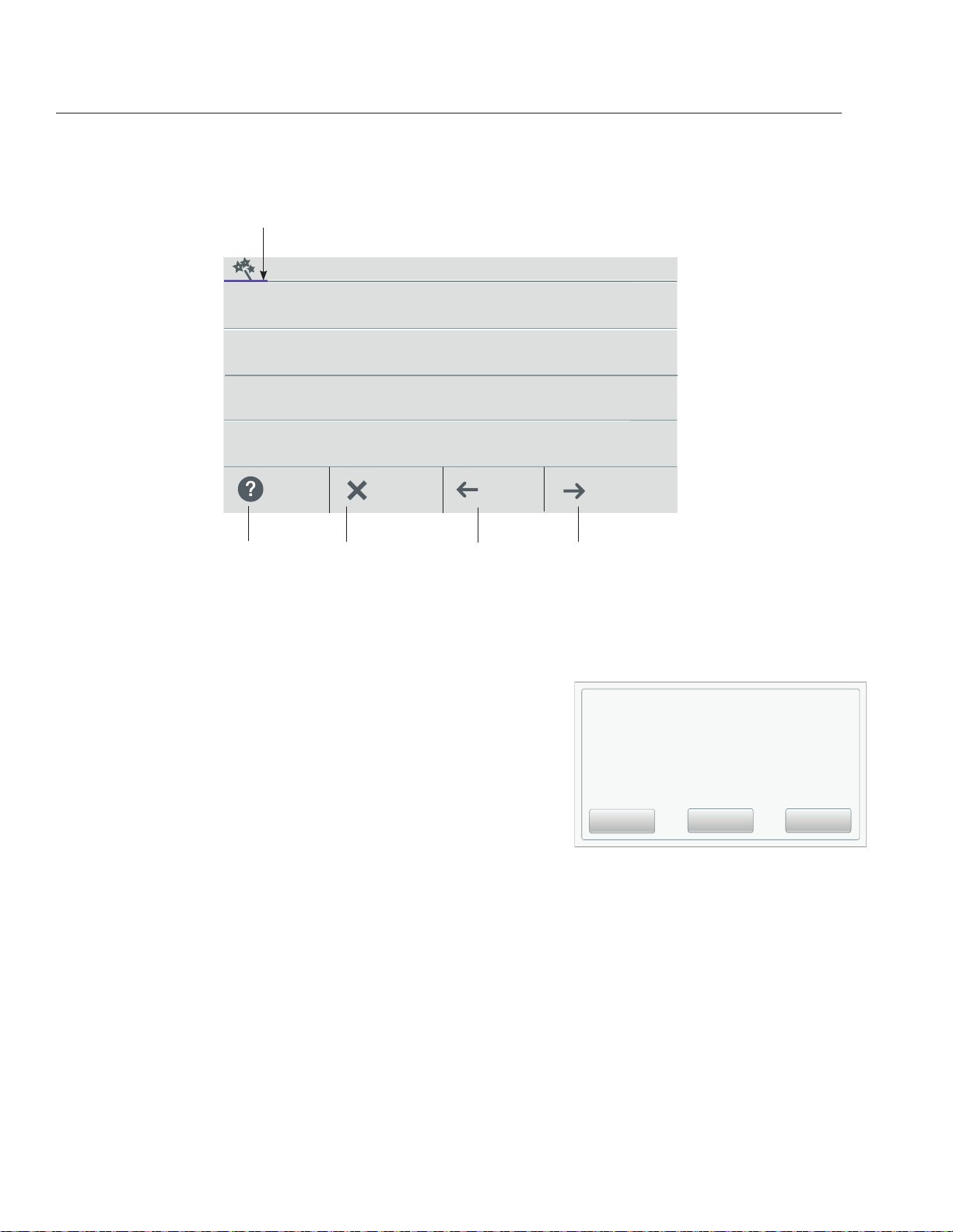
40
What is your Zip code / Locaon
Home
Setup Wizard [Advanced System Conguration]
Setup Wizard Screen Navigation:
Note: While in the Configuration Wizard, if a power outage occurs or the screen times out, the
system will display the Home Screen. Any changes made in the Wizard up to that occurrence will
be saved.
Zip Code
11220
Brooklyn, NY
United States
Latude
Y Coordinate
40.65°
Longitude
Y Coordinate
-73.94°
Time Zone
Eastern Time (US & Canada)
Help/ Exit
Back/
Menu
Progress Bar Indicator: The Blue Configuration Wizard progress bar indicates how many option
have been completed.
Help ?: Brief informative information for the current Setup Wizard screen.
Cancel (Exit Wizard?): Tap the Cancel button while in the
Setup Wizard to display the following dialog screen:
No to remain in the Setup Wizard and return to previous
Wizard screen and continue with the Setup Wizard
configuration.
Yes to save any changes made up to this point,
exit the Setup Wizard and return to the Home Screen.
Discard: Discard all changes made in the Setup Wizard, exit
the Setup Wizard and return to the Home screen.
UTC/GMT -5
Next/
SummaryWizard
Exit Wizard?
No: Remain in the Setup Wizard and return to
previous Wizard screen and continue with the Setup
Wizard configuration.
Yes: Save any changes made up to this point, exit the
Setup Wizard and return to the Home screen.
Discard: Discard all changes made in the Setup Wizard,
exit the Setup Wizard and return to the Home screen.
No
Yes Discard
Back: Return to the previous screen.
Next: Move to the next Wizard screen or item settings.
Example: Before each Wizard configuration screen a YES/NO option screen is displayed. Tap
YES then NEXT to enter the item configuration screen. Tap NO then NEXT to continue to the
next option.
Note: Number of Configured Devices: Displayed on the first of each Wizard option screen is the number of devices
that have been configured. As you progress through the Wizard the device message corresponds to how many options
have been updated.
IntelliCenter Control System Installation Guide IntelliCenter Control System Installation Guide
Page 49

Setup Wizard [Advanced System Configuration]
Menu Home
Summary
Wizard
Wizard
Initial System Power Up
After all required pool/spa equipment has been connected to the IntelliCenter Control System, apply
power to the system at the main panel circuit breaker. Upon the initial system power up, the outdoor
LCD control panel will display the PENTAIR END USER LICENSE AGREEMENT. Please read this
agreement. To continue, tap the Down arrow on the right side of the screen to scroll down to the end
of the agreement and tap I Accept to accept the agreement. The Home screen is then displayed.
Note: The Pentair End User License Agreement is displayed only one time after the initial system
power up.
PENTAIR END USER LICENSE AGREEMENT
IntelliCenter Control System
I Accept
41
Wizard Setup: To start the Wizard system setup, from the Home screen, tap Settings > Advanced
System Configuration > Wizard. The following screen is displayed.
IntelliCenter™ Control System Setup
IntelliCenter Control System Setup
Wizard: The first Setup Wizard configuration
Welcome!
screen, Displays the current system
firmware version.
The IntelliCenter™ Control System Setup Wizard
will guide you through the system
configuraon for your pool/spa equipment.
Next: Tap Next to continue with the Setup
Wizard and display the Detected Hardware
screen.
Help/
Menu
Exit
Firmware version 1.0
Next
Cancel: Tap Cancel to exit the Setup
Wizard and return to the Home screen.
Import System Configuration:
Import a System Configuraon?
Yes: Use this option to Import a system
configuration file (.CFG) from a USB device
plugged into the USB Port on the front of the
Import Configuraon?
Cauon! If you import a system configuraon
file, this opon will overwrite the current
configuraon.
Help/ Back/
Exit
YES
Next/
IntelliCenter Control System Outdoor control
panel. Note: This option will overwrite the current
system configuration.
No: Tap No then Next to continue with the Setup
Wizard.
Note: See page 84 for information about OverThe-Air IntelliCenter Control System softwars
updates.
Page 50

42
Menu Home
SummaryWizard
Menu Home
Summary
Wizard
What is your Zip code / Locaon
Home
Setup Wizard [Advanced System Configuration]
Import for USB: Insert a USB device into the USB Port on the IntelliCenter
Indoor control panel. Tap Import from USB and navigate to the system configuration file (.CFG). Follow the
on screen instructions to import the system configuration files plugged into the USB Port on the Outdoor or
Indoor control panel.
Local or copy from Remote: These options will overwrite the system configuration using a
configuration file. Navigate to the appropriate folder and select the Configuration file (.cfg) to import.
®
Control System Outdoor or
Detected Hardware
Setup had detected the following hardware:
Personality: i5PS
Expansion Module1: None
Expansion Module2: None
Expansion Module3: None
Expansion Module4: None
Help/ Back/
Zip Code
11220
Latude
Y Coordinate
Longitude
Y Coordinate
Time Zone
Eastern Time (US & Canada)
Help/ Exit
Menu
Would you like to set the Date & Time?
Update Date & Time
Help/ Back/
Exit
Brooklyn, NY
United States
UTC/GMT -5
Back/
Jan. 12, 2018 6:60 pm
YES
Exit
Next/
40.65°
-73.94°
Next/
SummaryWizard
Next/
Detected Hardware: Displays the installed IntelliCenter
Control System Personality main circuit board and Expansion
Cards (if applicable).
Next: Tap Next to continue to the Zip Code / Location
settings screen.
Back: Tap Back to go to the previous screen.
Cancel: Tap Cancel to exit the Setup Wizard and display the
Exit Wizard screen (No, Yes, Discard options).
Update date & Time: Tap Yes and Next to update the system
date and time.
Clock Mode: Select either 12 hour or 24 hour mode.
Daylight Saving Time: Select ON to automatically set the
yearly daylight saving time for your location. Select NO to
manually change the daylight savings time for your location.
Converting a 12 hr. time to 24 hr. (Military time) is from 1:00 PM
to 11:59 PM, then add 12 hours, and from 12:00 AM (midnight)
to 12:59 AM subtract 12 hours.
Zip Code / Location Screen: After the IntelliCenter Control
System has verified the login information successfully, the
Location screen is displayed. Tap any setting to update the
location information. Tap Zip Code to enter your Zip code for
your location. The US Zip code information will automatically
populate the Latitude and Longitude coordinates and Time
Zone via a Broadband Internet connection.
Note: If the PC time and date do not match the time and date
displayed on the Home screen. Match the PC time and date to the
IntelliCenter Control System.
Location: The US Zip code, Latitude, and Longitude coordinates and Time Zone information will
automatically populate via a Broadband Internet connection. You can also enter the information manually.
Time Zone (UTC): UTC−05:00 (Brooklyn New York) is a time offset that subtracts five hours from
Coordinated Universal Time (UTC). In North America, it is observed in the Eastern Time Zone during
standard time, and in the Central Time Zone during the other eight months (see Daylight saving time). The
western Caribbean uses it year round.
Note: Time and date synchronization for all systems may take a few minutes.
IntelliCenter Control System Installation Guide IntelliCenter Control System Installation Guide
Page 51

AUX Circuits-OCP
Menu
Home
Sumary
Wizard
Configure Circuits
Menu Home
Summary
Wizard
Menu Home
Summary
Wizard
Setup Wizard [Advanced System Configuration]
Update Date & Time
Menu Home
Summary
Wizard
Time Set: Tap the Time Set time button and set the
current time for your location. Tap Check to save and
Time Set
4:00 pm
return to the previous page.
43
Date Set
Jan 12, 2018
Date Set: Tap the Date Set time button and set the
current date. Tap Check to save and return to the
Offset (min/month)
OFF
previous page.
Offset (min/month: Select ON to offset the current
Help/ Back/
Exit
Next/
time (minutes) and month
.
Configure AUX CIRCUITS: Setup system AUX circuits.
Create an AUX Circuit?
Spa
Generic
AUX1
Configure
AUX Circuits?
Help/ Back/
Exit
YES
Next/
Generic
AUX2
Generic
AUX3
Generic
Help/
Create AUX Circuit: Tap Yes then Next to configure an AUX Circuits. Tap No then Next to continue to
Configure Feature Circuits.
Circuit Funcon: Booster Pump
Circuit Funcon: Generic
Circuit Funcon: Generic
Circuit Funcon: Generic
Exit
Back/
Next/
Select an AUX Circuit: Tap on an AUX Circuit name. From the next screen
configure the AUX settings:
Circuit Function: Select the Circuit Function.
Circuit Name: Select a Circuit name from the pre-defined list of custom circuits names, then tap Check to
save and return to the previous screen.
Visible in Features: Yes/No. Select Yes to display the selected circuits in the
Feature screen on Home screen.
Egg Timer: Select ON to select a manual time-out of 0-12 hours for this circuit. The Egg Time is a specified
time delay (hrs/mins) for the circuit, once it is turned on.
Freeze Protection: Assign freeze protection for this circuit.
Create / Modify: Tap Next after the first AUX Circuit
has been configured. The Configure Circuits screen is
displayed. Select either Create or Modify to
create a new circuit or modify an existing AUX Circuit.
Create Modify
After you have configured all of the available AUX
Circuits, tap Next to continue to Feature Circuits.
1 AUX Circuit has been configured.
Tap Next to modify an exisng AUX Circuit seng.
Help/ Back/
Exit
Next/
Page 52

44
Menu Home
Summary
Wizard
Menu Home
Summary
Wizard
Setup Wizard [Advanced System Configuration]
Configure Feature Circuits: Configure Feature circuits (maximum 32).
Create a Feature Circuit?
Configure Circuits
Configure
Feature Circuits?
Help/ Back/
Exit
YES
Next/
1 AUX Circuit has been configured.
Tap Next to modify an exisng AUX Circuit seng.
Help/ Back/
Create Modify
Exit
Next/
Create / Modify: Tap Next after the first AUX Circuit has been configured. The Configure Circuits screen
is displayed. Select either Create or Modify to create a new circuit or modify an existing AUX Circuit. After
you have configured all of the available AUX Circuits, tap Next to continue to Configure Valves.
Create Feature Circuit: Tap Yes then Next to configure Feature Circuits. Tap No then Next to continue to
Configure Feature Circuits.
Select a Circuit Function: Tap on either Generic or Spillway for the circuit function. From the next screen
configure the Feature Circuit settings:
Circuit Function: Select either Generic or Spillway.
Circuit Name: Select a Circuit name from the predefined list of custom circuits names, then tap Check to
save and return to the previous screen.
Visible in Features: Yes/No. Select Yes to display the selected circuits in the
Feature screen on Home screen. Tap Next to continue.
Egg Timer: Select ON to select a manual time-out of 0-12 hours for this circuit. The Egg Time is a
specified time delay (hrs/mins) for the circuit, once it is turned on.
Freeze Protection: Assign freeze protection for this circuit.
VALVES
Configure Valves: Tap Yes then Next to configure a new valve type. Tap No then Next to continue to
Configure IntelliChlor SCG.
Intake (standard), Return (standard): To change the valve name, tap Intake or Return. Tap Valve name,
enter the new valve name then tap Check to save and return to the previous screen.
Valve A and Valve B (Model i10D): If the optional Valve Module installed, Valve A and Valve B are
displayed. To change the valve name, and assign a circuit to Valve A and Valve B, tap Valve A or Valve B on
this screen.
Valve Name: To change the valve name, tap Intake or Return. Tap Valve name, enter the new valve name
then tap Check to save and return to the previous screen.
Assigned Circuit for Valve A or Valve B: Tap unassigned, and select an AUX circuit for the valve. Tap
Check to return to the previous screen. Tap Valve name, enter the new valve name then tap Check to save
and return to the previous screen.
IntelliCenter Control System Installation Guide IntelliCenter Control System Installation Guide
Page 53

Setup Wizard [Advanced System Configuration]
PUMPS
45
Tap Yes then Next to configure a new pump (Tap No then Next to continue to Configure Heaters.
®
Create: Tap Create then Next to select a new pump type (IntelliFlo
VF pump, IntelliFlo VS pump, IntelliFlo
VSF pump, Single Speed, Dual Speed) and configure the pump settings.
Modify: Tap Modify then Next to display the list of configured pumps. Tap New Pump to add a pump. From
this screen you can add or delete pumps from the list. When finished with setting up pump settings, tap
Next to continue to the Configure Heaters screen.
IntelliFlo VF Settings: Tap Settings: Pump Type (select a different type of pump), Pump Name (enter
a name for the pump), Pump Address: select an address for the pump (1-16). Tap Back twice. Tap Flow
Circuits. Tap New Flow Circuits (to change the pump circuit). Flow (GPM): Tap the -/+ button to set the flow
rate (15-134 GPM). Tap Next twice to add another pump or tap Next twice to configure a heater.
IntelliFlo VS Settings: Tap Settings: Pump Type (select a different type of pump), Pump Name (enter a
name for the pump), Pump Address: select an address for the pump (1-16). Tap Back twice. Tap Speed
Circuits. Tap Speed Circuits. Tap New Speed Circuits (to change the pump circuit). Speed (RPM): Tap the
-/+ button to set the pump speed (450-3450 RPM). Tap Next three times to configure a heater.
IntelliFlo VSF Settings: Tap Settings: Pump Type (select a different type of pump), Pump Name (enter a
name for the pump), Pump Address: select an address for the pump (1-16). Tap Back twice. Tap Speed/
Flow Circuits. Tap New Speed/Flow Circuits (to change the pump circuit).
Type: GPM/RPM): Select either GPM (40-134) or RPM (450-3450). Tap the -/+ button to set the speed
(RPM) or Flow Rate GPM). Tap Next twice to add another pump or tap Next twice to configure a heater.
Single Speed Pump Settings: Pump Type (select a different type of pump), Pump Name, and Body (pool,
spa or pool/spa). Tap Return then Next to continue and add another pump or tap No twice to configure a
heater.
Two Speed Pump Settings: Tap Settings: Pump Type (select a different type of pump), Pump Name,
Low Speed Circuit and High Speed Circuits. Select a circuit for the low speed and the high speed. You can
choose up to (4) four high speed circuits.
HEATERS
Tap Yes then Next to configure a new heater (Tap No then Next to continue to Configure Pumps).
Create: Tap Create then Next to select a new heat source type (Gas, Solar, Heat Pump, UltraTemp or
Hybrid) and configure the selected heat source settings.
Heater Name: Enter a name for the heater.
Affiliated Body: Pool, Spa, or Pool and Spa.
Modify: Tap Modify then Next to display the list of configured heaters. Tap New Pump to add a heat source.
From this screen you can add or delete a heat source from the list. When finished with setting up heater
source settings, tap Next to continue to the Configure Valves screen.
+ Add Heater: Tap Add Heater to display the available heaters. When finished configuring up the heater
settings. Tap Next to continue to the Configure Remotes screen.
Page 54

46
Setup Wizard [Advanced System Configuration]
REMOTES
QuickTouch® Remote:
• To setup a QuickTouch remote, select Yes. If there is no QuickTouch remote installed, select No and tap
Next to continue.
• Remote Name: You can change the name of the remote and assign the remote's four buttons equipment
functions to control.
• Enable Remote ON/OFF): To enable the remote select ON. Tap Next to continue.
• Button Assignments: Tap Configure. Tap Button 1, then tap the AUX circuit button for this circuit. Tap Back
and repeat for buttons 2-4. When all buttons have been assigned, tap Return arrow until SpaCommand
remote screen is displayed. Tap Next to continue.
iS4 Remote
• To setup a iS4 remote, select Yes. If there is no iS4 remote installed, select No and tap Next to continue.
• Remote Name: If needed, you can change the name of the remote.
• Enable Remote ON/OFF): To enable the remote select ON. Tap Next to continue.
• Button Assignments: Tap Configure. Tap Button 1, then tap the AUX circuit button for this circuit.
Tap Back and repeat for buttons 2-4. When all buttons have been assigned, tap Return arrow until
SpaCommand remote screen is displayed. Tap Next to continue.
iS10 Remote: To setup a iS10 remote, select Yes. If there is no iS10 remote installed, select
No and tap Next to continue.
• Remote Name: If needed, you can change the name of the remote.
• Enable Remote (ON/OFF): To enable the remote select ON. Tap Next to continue.
• Remote Channel: Asign a channel from 1-4. Tap Return.
• Affected Pump: Select pump assigned to this remote.
• Button Assignments: Tap Configure. Tap Button 1, then tap the AUX circuit button for this circuit.
Tap Back and repeat for buttons 2-9. When all buttons have been assigned, tap Return arrow until
SpaCommand remote screen is displayed. Tap Next to continue.
SpaCommand® Remote: To setup a SpaCommand remote, select Yes. If there is no
SpaCommand remote installed, select No and tap Next to continue.
• Remote Name: If needed, you can change the name of the remote.
• Enable Remote (ON/OFF): To enable the remote select ON. Tap Next to continue.
• Remote Channel: Asign a channel from 1-4. Tap Return.
• Affected Pump: Select pump for this remote.
• Button Assignments: Tap Configure. Tap Button 1, then tap the AUX circuit button for this circuit.
Tap Back and repeat for buttons 2-9. When all buttons have been assigned, tap Return arrow until
SpaCommand remote screen is displayed. Tap Next to continue.
Chemical Controllers: IntelliChem® Controller and IntelliChlor® SCG
Note: One IntelliChem Controller and one IntelliChlor® SCG can be installed one IntelliCenter Control
System.
IntelliChem Controller: Tap Yes then Next to configure one IntelliChem. Tap No for no IntelliChem
Controller installed. IntelliChem Settings: Select the Channel (1-16) for the device.
Body 1 is assigned Pool/Spa for shared equipment or choose pool or spa for single body systems, Body 2
is assigned to Spa for shared equipment systems. This screen displays the body of water assigned to the
device.
IntelliChlor SCG: Tap Yes then Next to configure one IntelliChlor SCG. Tap No for no IntelliChlor SCG
installed.
Body 1 is assigned Pool/Spa for shared equipment or choose pool or spa for single body systems, Body 2
is assigned to Spa for shared equipment systems. This screen displays the body of water assigned to the
device.
Chlorination Output Levels: Pool /Spa Output Levels: Set the Pool and Spa chlorine output levels.
The system can only generate chlorine while the filter pump is operating. Set the run time percentage to
produce chlorine. The higher the percentage the more chlorine is produced. Lower the percentage for less
chlorine production.
IntelliCenter Control System Installation Guide IntelliCenter Control System Installation Guide
Page 55

Setup Wizard [Advanced System Conguration]
Menu Home
Summary
Wizard
Setup Wizard Summary
SCHEDULES
Create Schedules?
Create Schedules?
YES
If Yes then Next to configure system schedules.
If no schedules are required at this time, tap No then Next to continue
to the Setup Wizard Summary screen.
47
Help/ Back/
Exit
Next/
Create / Modify: Tap Create then Next and choose a circuit to schedule. Tap Modify to change an existing
schedule.
Create a Schedule: Tap Create then Next. From the Schedules screen, tap Add Schedule and choose the
circuit. Tap Next. From the Schedule Settings screen, tap the Schedule name button (Weekly or One Time)
and select the days to run the schedule. Tap Check when finished to save the schedule.
Start Time: From the Select Start Time screen, tap the Up/Down arrow button to set the Start time for
the schedule. Tap Check to save and return to the previous screen. Tap Next to continue to the Stop Time
screen.
Stop Time: From the Select Start Time screen, tap the Up/Down arrow button to set the Start time for the
schedule. Tap Check to save and return to the previous screen. Tap Next to continue to the next scree. Tap
Yes to add more schedules, if not tap No to continue to the Setup Wizard Summary screen.
SUMMARY
Setup Wizard Summary (Edit Screen)
From the Setup Summary screen you can review the changes you have made to the system. If
modifications are necessary, tap the option name and make the changes. If everything appears to be
correct, press Next to continue to the Setup Wizard Complete screen.
Date & Time
United States 11220
Zip Code
Time Zone
AUX Circuits
Help/ Back/
Menu Home
East Time (US & Canada) UTC-4
4 Circuits are configured
Exit
Wizard
Brooklyn, NY
11220
Next
Page 56

48
Pool Spa Features Lights
Air Temp 65° F
Schedule Usage Chemistry Status
3 3
10:10 am
6.50
0
4
84°
78°
Setup Wizard [Advanced System Conguration]
Setup Wizard Complete
The Setup Wizard configuration has been successfully
completed.
Back: Return to the previous screen and continue with
the Setup Wizard.
Export: Exit the Setup Wizard and go to the IMPORT /
EXPORT screen to save the configuration to a USB.
Finish: Save the configuration and go to the Home
screen.
Setup Wizard is Complete
Back
Export to USB
Export Finish
Back: Return to the previous screen and continue with the Setup
Wizard.
Export: Go to the Export System configuration screen. Tap Yes then
Next, select a folder location, tap Check to save the export file. Tap
OK to return to Wizard Complete screen. Tap No then Next to return
to the Wizard Complete screen. Tap No IMPORT / EXPORT screen
to save the configuration to a USB.
Export System Configuration: Tap Export to USB flash drive to
export the current system configuration.
Export to Local: Tap Export to Local to save the current system
configuration.
Save Locally
Export Local Configuraon to USB
Back: Return to the Create Schedule screen.
Finish: Save the configuration and go to the Home screen. "Applying Settings" is displayed, then the
Home screen is displayed. The Setup Wizard has been successfully completed.
Home Screen
Screen Settings
To access the screen settings, from the Home screen, tap Settings > Advanced System Configuration >
General > Day/Night Theme,
Back Light: Brightness Level: Adjust the screen brightness level from 33 to 100%.
Dimness Level: Adjust the contrast level from 10 to 100%.
Dim Display (min): While in other screens, sets the time to return to the Home screen (from 0 to 240
minutes (20 hrs).
Turn Off Display (min): Set the time to turn off the screen from 0 to 240 minutes (20 hrs).
Note: The time set to turn off the screen also affects the start time of the Deep Sleep feature (Wireless
Remote only), see below for details.
Battery Conservation Mode (Deep Sleep): Tap Deep Sleep Mode to turn on this feature. The default setting is ON. This
feature allows you to save the battery life while the wireless remote is in its cradle. Deep Sleep (Hr): Deep Sleep time
can be set from 1 to 3 hours (Default 3 hrs.). Select when you want the device to go to sleep to conserve battery life.
IntelliCenter Control System Installation Guide IntelliCenter Control System Installation Guide
Page 57

IntelliCenter® Control System Menu
Home Screen
Pool Screen
Spa Screen
Features (Individual/Groups)
Lights (Individual/Groups)
Schedule (Weekly, One Time Only Schedule)
Usage
®
Chemistry (IntelliChem
Controller/IntelliChlor® SCG)
Status
Settings
Service Mode
Vacation Mode
Support
General: Location, Date & Time, Units (Fahrenheit/Celsius), Features
and Lights List Order, General List Order, Backlight (Deep Sleep): Wireless
Control Panel only, Temperature Sensor Calibration, Day / Night Themes,
Manual Operation Priority, Manual Heat, Chemistry Readings Badge, Badge
Colors.
Alerts and Notifications: Choose which system status, alerts and warnings
badges to display on the Home screen Status icon.
Security (Passcode Protect)
Pentair User Portal (intellicenter.com)
Groups: Configure groups of AUX circuits, Light circuits and Feature circuits.
System Reboot: Reboot the panel
Advanced System Configuration
Installation Setup:
49
Body Configuration,Circuits, Pumps, Heaters, Valves,
Chemistry, Pool/Spa Cover.
Remotes Setup: iS4, QuickTouch II, iS10, SpaCommand remotes
Network and WiFi Setup: (Not required for Wireless 900MHz High Power Wireless
Link Kit (P/N 523434). Please refer to the provided installation instructions (P/N 523445)
when installing the 900 MHz Wireless antenna. Configure Ethernet, Connect to a Wireless
Network, Adjust Wireless Transmit Power, Internet Connection Test, Reboot Wireless
Device.
IntelliCenter Wireless Remote Setup: Configure the Address and Panel #
for wireless remote.
Delays: Valve Delay, Heater Cool Down, Freeze Cycle Time (min), Spa Freeze
Override (min), Override Delays.
System: System Information, Detected Hardware, System Diagnostic
Information, Firmware Update (Update from Panel, Update from USB,
Update from Ethernet), Factory Diagnostics.
Import/Export: Import System Configuration, Export System Configuration.
Restore Factory Defaults: Restore system to factory configuration.
Setup Wizard: Step-by-step system configuration.
Page 58

50
Pool Spa Features Lights
Air Temp 65° F
Schedule Usage Chemistry Status
3 3
10:10 am
6.50
0
4
84°
78°
Select Heat Mode
OFF
Heater
Solar Preferred
Solar Only
Heat Pump
Heat Pump Preferred
Pool
Temp
77
Pool
°
Heang
Set Point
78
°
Heater
Heat Mode
Pool
Spa
Heang
Set Point
87
°
Spa
Heater
Pool
Temp
77
°
Heat Mode
Flame: Snow Flake: Sun:
Heat Source Nocturnal Solar
Active Cool Down Heat Source
IntelliCenter® Control System Test
The following describes how to test the IntelliCenter Control System Outdoor Control Panel to
activate the heater, valves and pumps. This test assumes that all system equipment has been
properly installed and connected to the IntelliCenter Control System Load Center.
Testing Valve Actuators and Pumps
Use the following steps to test the valve actuators (CVA24T) for proper rotation for i5PS IntelliCenter
Control System (shared equipment).
To test the valve actuators and pump:
1. Switch on the main circuit breakers to apply power to the IntelliCenter Control System Load Center.
2. Pool and Spa Pump and Heater Test: From the Home screen, tap Pool > Pool (or tap Spa >
Spa) to activate the pool pump (or Spa pump) and heater. Tap the Heat Mode button and select
a different heat source. The Heat Mode button indicator is Red to indicate the heater is on, Blue is
heater cool down mode. When the heater is on a flame indicator is shown on the Home screen pool
Green badge. Tap Return to return the Home screen.
Heat Mode button indicator:
IntelliCenter Control System Installation Guide IntelliCenter Control System Installation Guide
Spa Manual Heat ON/OFF Feature: Spa Manual Heat ON/OFF Feature: If the Heat Enabled
(Default ON)feature is selected (see Spa Body Configuration >Spa Settings) when the Spa pump
button (or from the Spa-Side remote, or Wireless Controller) is manually turned on, the pump will
turn on and the heater will begin to heat the spa (even if the heater is set to OFF). This feature
allows you to program the pool pump to filter daily with the heater set to off, and then be ready to
heat whenever the Spa button is pressed.
Pool Badge Icons: A Flame icon is displayed with the current
heat set point temperature. The Spa badge icon indicates that the
heat source has been called for.
UltraTemp Heat Pump, Hybrid Heater or Solar Heat (if enabled) is in
cooling mode. A Sun icon indicates solar heat is active. Select the
heat source from the Select Heat Source screen.
A Snow Flake icon indicates the
Page 59

51
Service Mode
Enabling Service Mode will disable all circuits that are
currently acve.
Auto Service Timer
Manual Circuit Control
Testing Valve Actuators and Pumps
(Continued)
3. Testing equipment auxiliary circuits: From the Home screen, tap Settings > Service Mode >
Service. Note: Service Mode is displayed on the Home screen.
4. Tap Manual Circuit Control. To test the equipment, tap the displayed circuits (pump, aux, solar,
heater) to confirm proper operation. When the pool circulation pump is on water will flow from the
pool and returned into the pool. The Green radio button is lit when equipment is manually switched
on. Grey indicates the circuit is off.
5. After testing the auxiliary circuits, tap the Return arrow to return to the Service Mode screen. Tap
Auto to return the system to operating mode. Tap and hold the Return arrow to return to the Home
screen.
6. Manual Test V alve Actuators: Set both valve actuators (CVA-24T) for suction and return. Use the
toggle switch on the rear of the CVA-24 to withdraw and return water from the pool.
Note: With the circulation pump operating, if the water is not being removed and returned to the
pool, it may be necessary to toggle the valve ON1 and ON2 switch (or vice versa).
Solar Valve T est
1. Switch on the main circuit breakers to apply power to the IntelliCenter® Control System load center.
2. Check that Solar Valve is in solar bypass position, diverting water away from solar panels. If Solar
Valve is staged incorrectly (diverting water to the solar panels), reverse switch on back of Valve
Actuator (change from ON1 to ON2, or vice-versa). The Valve Actuator will automatically rotate to
the correct position.
3. Check that Solar Valve has rotated from the “solar bypass” position to the “solar” position, diverting
water through the solar panels.
4. The system is now ready to be operated as desired.
HEATER CONNECTIONS: Note: iS5PS/i10D: Pool/Spa Heater Connections - It does not matter which body of water is connected to each heater
connector. The heater on the main i5P board is for body 1 (pool or spa), and the heater on the i10D board is for body 2 (pool or spa).
Page 60

52
Installing the Outdoor Control Panel in the Load Center or Power Center
BEFORE INSTALLING THE OUTDOOR CONTROL PANEL IN THE LOAD CENTER,
ALWAYS SWITCH OFF AC POWER AT THE MAIN HOUSE CIRCUIT BREAKERS.
The IntelliCenter
®
Control System Outdoor Control Panel installs in the top part of the Load Center
enclosure. The control panel controls and distributes high voltage power to the valve actuators,
control pumps, lights, and heater operations. The optional IntelliCenter Control System Indoor
Control Panel, Wireless Controller, SpaCommand®, iS10, iS4 and QuickTouch® Remote Controllers
also controls these and other functions, such as pool and spa lights.
To install the Outdoor Control Panel:
1. Unlatch the front door spring latch and open the front door of the Load Center enclosure.
2. Loosen the two (2) retaining screws securing the high voltage cover-panel. Remove the HIGH
VOLTAGE COVER PANEL from the enclosure (as shown on below).
3. Remove the Outdoor Control Panel from its packaging.
4. Mount the Outdoor Control Panel in the top part of the Load Center. Secure the lower edge of the
control panel with the two retaining screws. Once secured, the Control Panel can hinge out and
down to access the circuit board and the low voltage connections.
5. When finished connecting the low voltage connections on the circuit board, close the hinged control
panel and secure it with the two retaining screws. Reinstall the High Voltage Panel: Insert the
panel’s three tabs into the lower slots on the enclosure. Secure the panel with the two (2) retaining
screws. Close the front door and secure with the latch.
Loosen Outdoor Control
Panel retaining screws
Front door
LOW VOLTAGE
RACEWAY
Flip down the Outdoor Control Panel to
access circuit board and low
voltage compartment
Remove two (2) retaining screws
securing High Voltage Cover Panel
High Voltage Cover Panel slots (3)
High Voltage Cover Panel Tabs (3)
IntelliCenter® Load Center Control System Load Center (front view)
(High Voltage Cover Panel removed)
IntelliCenter Control System Installation Guide IntelliCenter Control System Installation Guide
Page 61
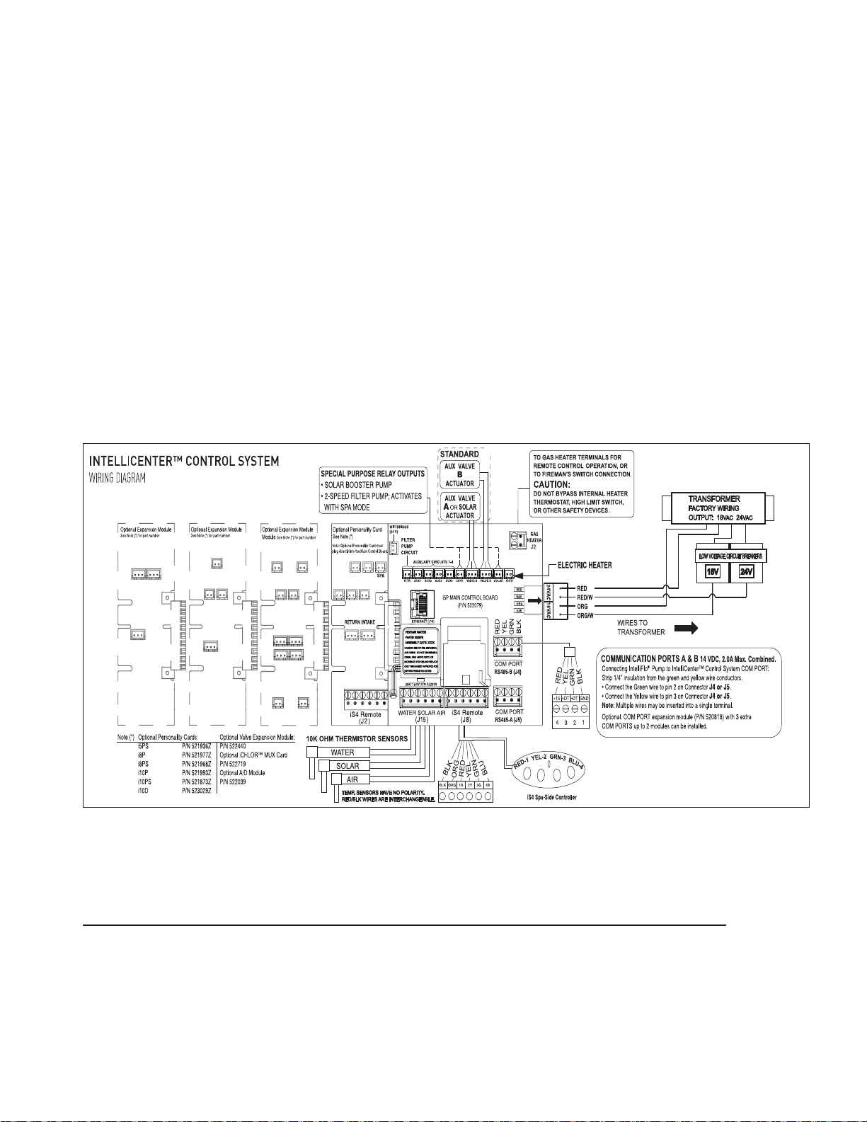
IntelliCenter® Control System Personality Boards
AUX5 AUX6
AUX7 AUX8 AUX9
For IntelliCenter Control System can be configured for single body or dual body (shared equipment).
The base configuration is the i5P (five auxiliary pool circuits plus a filter pump circuit for a single
body of water). By adding a Personality circuit board the system can be expanded to support pool
and spa (i5PS - shared equipment, dual body of water) or dual equipment.
The following are IntelliCenter Control System Personality Models:
P/N 521909 IntelliCenter Control System i5P, Single Body
P/N 521910 IntelliCenter Control System i8P, Single Body
P/N 521911 IntelliCenter Control System i10P, Single Body
P/N 521912 IntelliCenter Control System i5PS, Shared Equipment
P/N 521913 IntelliCenter Control System i8PS, Shared Equipment
P/N 521914 IntelliCenter Control System i10PS, Shared Equipment
P/N 521915 IntelliCenter Control System i10D, Dual Equipment
P/N 522033 IntelliCenter Control System i5X Expansion
P/N 522034 IntelliCenter Control System i10X Expansion
53
IntelliCenter Control System Circuit Board
(with optional Expansion Boards shown)
Note: iS5PS/i10D: Pool/Spa Heater Connections - It does not matter which body of water is connected to each heater connector. The heater on the main i5P board is for body 1 (pool or spa), and the heater on the i10D board is for body 2 (pool or spa).
Page 62
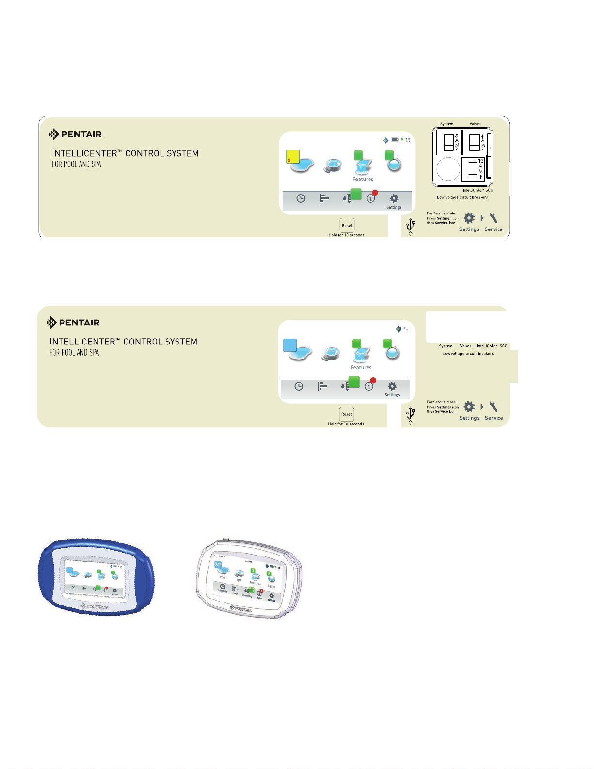
54
Pool Spa
Features Lights
Air Temp 65° F
Schedule Usage Chemistry Status
3
3
8:00 A.M.
6.50
0
4
78
°
Air Temp 65° F
10:10 am
IntelliCenter® Control System Outdoor Control Panels
For IntelliCenter Control System Outdoor Control Panel Wiring Diagrams, see pages 58-59.
Air Temp 65° F
78°
84°
8:00 A.M.
Pool Spa Features Lights
6.50
Schedule Usage Chemistry Status
IntelliCenter Control System Outdoor Control Panel (see page 63 for part numbers)
°
78
Pool Spa Features Lights
6.50
Schedule Usage Chemistry Status
3 3
4
0
3 3
4
0
IntelliCenter Control System Outdoor Control Panel (Retrofit for EasyTouch® or IntelliTouch® Control System Load Center)
IntelliCenter Control System
Wireless Controller
P/N 522036 (Optional)
IntelliCenter Control System
Indoor Control Panel
P/N 522035 (Optional - Maximum of two per system))
IntelliCenter Control System Installation Guide IntelliCenter Control System Installation Guide
Page 63

14.900 in
*522992*
IntelliCenter® Control System Load Center Wiring Diagram
55
IntelliCenter Control System Load Center Wiring Diagram
Page 64

56
14.25”
*522991*
IntelliCenter® Control System Power Center Wiring Diagram
IntelliCenter Control System Power Center Wiring Diagram
IntelliCenter Control System Installation Guide IntelliCenter Control System Installation Guide
Page 65

n
2-Pin 24VDC Socket
(to Power Module)
57
POWER ADAPTER CABLE
Power Module
900 MHz Wireless
Link to indoor
Transceiver
(home user)
I
Intellicenter.com
AUX 5AUX 6
AUX 7AUX 8AUX 9
From LAN Port
To Ethernet Port
Attach to back panel of load
center with adhesive double
backed tape (provided)
Ethernet (Cat5) Cable
(from wireless antenna)
(J14)
IntelliCenter™ Load Center Circuit Board
Control System Wireless Connections
®
ScreenLogic2
program
RJ45
IntelliCenter
234
1
LAN PORTS
Wireless Router
WAN
RJ45
RJ11 for DSL
Coax for Cable
RJ11
DSL or
Cable Modem
(RJ45 - CAT 5)
to Wireless Router
LAN Port
Ethernet Cable
Transceiver
Link to outdoor
900 MHz Wireless
AC Power Adapter
(Indoor wall outlet)
Page 66
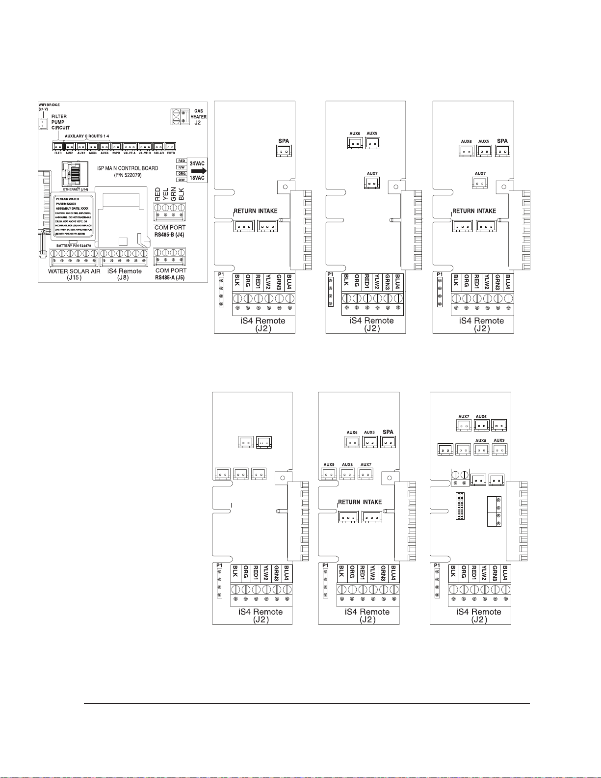
58
AUX7AUX8AUX9
AUX6AUX5
FLTR22SPD
SOLAREHTR
J3
SENSORS
WATER
SOLAR
AUX5
IntelliCenter® Control System Optional Personality Cards
i5P, Single Body
(P/N 521909)
i5PS, Shared
Equipment
(P/N 521912)
i10P, Single Body
(P/N 521911)
i8P, Single Body
(P/N 521910)
i10PS, Shared Equip.
(P/N 521914)
i8PS, Shared
Equipment
(P/N 521913)
i10D, Dual Equip.
(P/N 521915)
Note: iS5PS/i10D: Pool/Spa Heater Connections - It does not matter which body of water is connected to each heater connector. The heater on the main i5P board is for body 1 (pool or spa), and the heater on the i10D board is for body 2 (pool or spa).
IntelliCenter Control System Installation Guide IntelliCenter Control System Installation Guide
Page 67

IntelliCenter® Control System Optional Personality Cards
VLVGVLVF
VLVE
VLVH
VLVC VLVD
i10X Card
(P/N 522996)
AUX6 AUX7
AUX10 AUX9 AUX8
i5X Expansion
(P/N 522080)
59
AtoD Pool Cover Card
(P/N 522975)
ON C&K SDA 04
1 2 3 4
i10X Expansion
(P/N 522996)
(Requies i5X)
Valve Expansion
Module
(P/N 522038Z)
Analog to Digital
Pool Cover Card
(P/N 522039Z)
Page 68

60
IntelliCenter® Control System Kits
521903 IntelliCenter Kit i8PS, IC40, CLC (w/ Salt) -- Model Code: 8PSIC40
521904 IntelliCenter Kit i8PS, CLC (no Salt) -- Model Code: 8PS
521905 IntelliCenter Kit i5P, IC40, CLC (w/ Salt) -- Model Code: 5PIC40
521906 IntelliCenter Kit i5PS, IC40, CLC (w/ Salt) -- Model Code: 5PSIC40
521907 IntelliCenter Kit i5PS, CLC (no Salt) -- Model Code: 5PS
521908 IntelliCenter Kit i10PS, IC40, CLC (w/ Salt) -- Model Code: 10PSIC40
IntelliCenter Control System Personality Kits Only
521909 IntelliCenter i5P, Single Body
521910 IntelliCenter i8P, Single Body
521911 IntelliCenter i10P, Single Body
521912 IntelliCenter i5PS, Shared Equipment
521913 IntelliCenter i8PS, Shared Equipment
521914 IntelliCenter i10PS, Shared Equipment
521915 IntelliCenter i10D, Dual Equipment
522080 IntelliCenter i5X Expansion Panel
522996 IntelliCenter i10X Expansion Card (requies i5X)
IntelliCenter Control System Load Center (CLC) & Power Center (CPC) with Personality Kits
522041 CLC w/ IntelliCenter wiring Label), with IntelliChlor Transformer.
522042 CPC w/ IntelliCenter wiring Label), with IntelliChlor Transformer.
522043 CLC w/ IntelliCenter wiring Label), without IntelliChlor Transformer.
522044 CPC w/ IntelliCenter wiring Label), without IntelliChlor Transformer.
IntelliCenter Control System Upgrade Kits
522045 IntelliTouch/EasyTouch To IntelliCenter Upgrade Kit - i10P, for CLC/CPC
522046 IntelliTouch/EasyTouch To IntelliCenter Upgrade Kit - i10PS, for CLC/CPC
522047 IntelliTouch/EasyTouch To IntelliCenter Upgrade Kit - i10P, for CLC/CPC
522048 IntelliTouch/EasyTouch To IntelliCenter Upgrade Kit - i10PS, for CLC/CPC
IntelliCenter Control System Accessories
522035 IntelliCenter Indoor Control Panel Kit (MSaximum of two per system)
522036 IntelliCenter Wireless Kit
522038 IntelliCenter Valve Expansion Card (PCBA)
522039 IntelliCenter Pool Cover A/D Card (PCBA)
IntelliCenter Control System Installation Guide IntelliCenter Control System Installation Guide
Page 69

IntelliCenter® Control System Components
The required components of an IntelliCenter Control System is a Load Center and/or a Power
Center, IntelliCenter Control System Personality Kit, and Interface:
Load or Power Center
• Load Center: Footprint (26” H x 17” W x 5-1/4” D) Includes built-in sub panel (150 AMPS)
capable of holding up to eight 1” breakers. Also includes five 25 AMP three HP relays, 110/240 V
transformer with secondary side circuit protection. Multiple knockouts for different sizes of conduit
are supplied as well as a GFCI side knockout. The Load Center provides space for all high and low
voltage wiring needs.
• Power Center: Footprint (20” H x 17” W x 5-1/4” D). The Power Center does not include a circuit
breaker base. This enclosure is used with the Load Center.
IntelliCenter Control System Personality Kit Descriptions
The following lists types of IntelliCenter Control Systems available for different pool/spa
configurations:
• Shared Equipment: Pool and spa combinations with shared filtration system – Pool owners
can enjoy the convenience of motorized valves for water flow separation between pool and spa.
The Personality Kit models are:
61
i5PS (P/N 521912) – Four auxiliary circuits plus one dedicated filter pump relay (five relays total).
Five relays are included in the Load Center. Create a Feature circuit for valve actuators without
using an existing output auxiliary circuit, and special light functions for color lighting.
i8PS (P/N 521913) – Seven auxiliary circuits plus one dedicated filter pump relay (eight relays total).
Two relays are included in the Personality kit plus five relays in the Load Center. Create a Feature
circuit for valve actuators without using an existing output auxiliary circuit, and special light functions
for color lighting).
i10PS (P/N 521914) – Nine auxiliary circuits plus one dedicated filter pump relay (10 relays total).
Three relays are included in the Personality kit plus five relays in the Load Center. Create a Feature
circuit for valve actuators without using an existing output auxiliary circuit, and special light functions
for color lighting).
• Dual Equipment: Pool and Spa with Dual Sets of Equipment (i10D P/N 521915) – This system
is designed to operate two sets of pool equipment. Each set of a equipment (Pool or Spa) can
control one temperature setting.
i10D (P/N 521915) – Eight auxiliary circuits plus two dedicated filter pump relays (10 relays total).
Five relays are included in the personality kit and five in the Load Center.
• Single Equipment: Pool Only or Spa Only – This system is designed to operate a single body of
water (LO-TEMP and HI-TEMP). The Personality Kit models are:
i5P (P/N 521909) – Four auxiliary circuits plus one dedicated filter pump relay (five relays total).
Five relays are included in the Load Center.
i8P (P/N 521910) – Seven auxiliary circuits plus one dedicated filter pump relay (eight relays total).
Two relays are included in the Personality kit plus five relays in the Load Center.
i10P (P/N 521911) – Nine auxiliary circuits plus one dedicated filter pump relay (10 relays total).
Four relays are included in the Personality kit plus five relays in the Load Center.
Page 70

62
IntelliCenter® Control System Expansion Kits
• Expansion Kits: Models i5X (P/N 521033) and i10X (P/N 521034), offer five or ten additional
Auxiliary Circuits. Each IntelliCenter Control System Expansion Kit requires a Load Center (P/N
521213) or Power Center (P/N 521214). Up to three Expansion Kits and Load or Power Centers
may be added to a system, for control of up to 38 Auxiliary Circuits (40 auxiliary circuits i10x).
Optional IntelliCenter Control System Expansion Enclosures
Expansion enclosures can support all of the same high voltage connections as the main load to the
Load Center or Power Center. A total of three enclosures can be added for a total of 40 auxiliary
circuits that can support a maximum of four bodies of water. The Expansion enclosure supports
the same COM port connections, and includes two actuators and a Load Center or Power Center.
The Expansion enclosure can be expanded to include up to five actuators (with valve module P/N
520285). Refer to the IntelliCenter Control System Expansion Kit Installation Guide (P/N 520471) for
more information.
RS-485
Main IntelliCenter
Control System
Load Center
(i5P, i5PS, i8P,
i8PS, i10P, i10PS,
and i10D)
1 or 2 bodies of water (3 Expansion enclosures):
OCP0: Main Circuit board - i5P capability
EXP1: Exp Motherboard - i5X or i10X
EXP2: Exp Motherboard - i5X or i10X
EXP3: Exp Motherboard - i5X or i10X
Power Center
(with Expansion
Enclosure
Personality Kit i5x
or i10x),
(P/N 521041 with
IntelliChlor SCG
transformer)
(P/N 5212043 without
IntelliChlor SCG
transformer)
Connection via RS-485 COM Port
Additional
Expansion
Enclosure
3 or 4 bodies of water (3 Expansion enclosures):
OCP0: Master Motherboard - i5P capability.
Has to use one of the following Personality
Cards: i5PS, i8PS, i10PS or i10D
OCP1: Motherboard - i5P + any Personality Card.
Can use any of the 6 Personality
Cards. Note: Motherboard in OCP1 same as
OCP0 (OCP0 is Master)
EXP1: Exp Motherboard - i5X or i10X
Additional
Expansion Enclosure
(3 maximum - 40 circuits)
EXP2: Exp Motherboard - i5X or i10X
• Main Load Center or Power Center (all models) = 2 (A & B)
• There are six (6) valves = 6 (C, D, E, F, G, H)
• Three (3) Expansion enclosures total
• One Valve module on Main Load Center (valve expansion card)
IntelliCenter Control System Installation Guide IntelliCenter Control System Installation Guide
Page 71

IntelliCenter® Control System Personality Kit Contents
The following items are included in the IntelliCenter Control System Personality Kit. If any item
is missing or damaged in the IntelliCenter kit, contact your authorized dealer, or contact Pentair
Technical Support (800.831.7133).
• An IntelliCenter interface Outdoor Control Panel. Includes a motherboard and a Personality circuit
board.
• Power Relays - i5P, i5PS, Qty. 0, i8P, i8PS, Qty. 3, i10P, i10PS, i10D, Qty 5, i5x, Qty. 0, i10x, Qty. 5 NOTE: 5 relays are provided in the Common Load Center or Power Center
• Valve Actuators – Qty. 2 (Models i5PS, i8PS, i10PS)
• Temperature Sensors – Water Sensor (25 foot cable, o-ring and hose clamp), Qty. 1, For i10D only,
Qty. 2 are provided. Air Sensor (with short cable).
• Wiring Diagram Label
• Common Load Center or Power Center parts bag: Includes relay screws.
• Label Sheet - A set of adhesive labels for custom identification (used to label the outdoor control
panel buttons). Use a pair of fine-tip tweezers to remove the labels from the sheet.
• IntelliCenter Personality Kit Installation Guide (this manual)
63
Optional IntelliCenter Control System Kit Contents
The following items are included in the IntelliCenter Control System kit which may also include the
optional IntelliChlor® SCG.
• IntelliCenter Control System Outdoor Control Panel (mounted in the load center)
• IntelliCenter Control System Common Load Center enclosure
• Motorized valve actuators (P/N 263045), Qty. 2 (not included with single-body system or dual
equipment)
• Temperature Sensors: Water Sensor (25 foot cable, o-ring and hose clamp), Qty. 1, For i10D only,
Qty. 2 are provided. Air Sensor (with short cable).
• IntelliCenter Control System Installation Guide (this manual)
Optional Equipment
• IntelliChlor
Salt Chlorine Generator model IC20 (P/N 520554) or
IC40 (P/N 520555), Power Center (P/N 520556 – if not integrated into the Common Load Center)
• IntelliChlor SCG User’s Guide (P/N 520589)
®
• IntelliChem
Controller no-pump (P/N 521357), one-pump (P/N 522621), two-pump (P/N 522622)
• IntelliChem Controller Installation and User’s Guide (P/N 521363
IntelliCenter Control System Upgrade Kits
• P/N 523472 - Easytouch® / Intellitouch® Control System Upgrade To IntelliCenter Control System
(For Legacy Systems 2003-2012)
®
• P/N 522455 - Easytouch
/ Intellitouch® Control System Upgrade To IntelliCenter Control System
(For Systems 2012 or Newer)
Page 72

64
Pool Spa
Features Lights
Air Temp 65° F
Schedule Usage Chemistry Status
3
3
8:00 A.M.
6.50
0
4
78
°
IntelliCenter® Control System Replacement Parts List
Kit Next Gen i5P OCP PCBA w/ Faceplate CLC/CPC P/N 523050
Kit Next Gen i5X Expansion PCBA w/ Faceplate CLC/CPC P/N 523051
NG i5PS Personality PCBA P/N 521936Z
NG i8P Personality PCBA P/N 521977Z
NG i8PS Personality PCBA P/N 521968Z
NG i10P Personality PCBA P/N 521993Z
NG i10PS Personality PCBA P/N 521873Z
NG i10D Personality PCBA P/N 523029Z
NG i10X Expansion Card PCBA P/N 522997Z
NG Faceplate, OCP, for CLC/CPC (with overlay) P/N 522004Z
NG Faceplate, IT/ET OCP Upgrade, for CLC/CPC P/N 522005Z
IntelliCenter Control System Accessory Equipment
IntelliCenter Control System Indoor Control Panel kit P/N 522035
IntelliCenter Control System Wireless Control Panel kit P/N 522036
IntelliCenter Control System Valve Expansion Card (PCBA) P/N 522038Z
IntelliCenter Control System Pool Cover Interface Card (PCBA) P/N 522039Z
SpaCommand® 10 Ten-Function Spa-Side remote, 150 ft. cable P/N 521176
Two-Speed Three HP Relay up to three additional valve actuators P/N 520198
Three HP Power Relay P/N 520106
®
QuickTouch
four-function wireless remote kit with transceiver assembly P/N 520148
QuickTouch II four-function wireless remote kit with transceiver assembly P/N 521245
IntelliChem
IntelliChlor
®
Controller P/N 521356
®
Acid Cleaning Kit P/N 520670
IntelliChlor Spacer pass-through cell for new pool start-up P/N 520588
IntelliCenter Control System
Indoor Control Panel (P/N 522035)
(maximum of two per system)
IntelliCenter Control System
Wireless Control Panel (P/N 522036)
SpaCommand
®
Spa-Side
QuickTouch
Controller (P/N 521176)
IntelliCenter Control System Installation Guide IntelliCenter Control System Installation Guide
®
Wireless Controller
(P/N 521245)
IntelliChem® Controller (P/N 521356)
Page 73

IntelliCenter® Control System Configurations and Models
65
PANEL: TYPE: CAPABILITY:
OCP0 i5P i5P Capabilities:
Single body of water (Pool or Spa)
Filter pump relay + 4 AUX relays
Valve A & B
Heater control (Gas & Electric)
Solar relay output
2-speed relay output
Water, Air, Solar Sensor
Two COM ports
Ethernet port
iS4 port
OCP0 i5PS i5PS Capabilities:
Shared equipment (Pool and Spa)
Intake & Return valves
Same as i5P (see above for details)
OCP0 i8P i8P Capabilities:
Single body of water (Pool or Spa)
Filter pump relay + 7 AUX relays
Same as i5P (see above for details)
OCP0 i8PS i8PS Capabilities:
Shared equipment (Pool and Spa)
Filter pump relay+ 7 AUX relays
Intake & Return valves
Same as i5P (see above for details)
OCP0 i10P i10P Capabilities:
Single body of water (Pool or Spa)
Filter pump relay+ 9 AUX relays
Same as i5P (see i5P for details)
OCP0 i10PS i10PS Capabilities:
Shared equipment (Pool and Spa)
Filter pump relay+ 9 AUX relays
Intake and Return valves
Same as i5P (see i5P for details)
OCP0 i10D i10D Capabilities:
Dual Bodies of water with separate
Pumps, Filters and Heaters
Note: Pool/Spa Heater
Connections - It does
not matter which body
of water is connected
to each heater connector. The heater on the
main i5P board is for
body 1 (pool or spa),
and the heater on the
i10D board is for body
2 (pool or spa).
Note: Pool/Spa Heater Connections - It does not matter which body of water is
connected to each heater connector. The heater on the main i5P board is for
body 1 (pool or spa), and the heater on the i10D board is for body 2 (pool or spa).
PANEL: CAPABILITY:
1 or 2 bodies of water:
OCP0: Main Circuit board - i5P capability
EXP1: Exp Motherboard - i5X or i10X
EXP2: Exp Motherboard - i5X or i10X
EXP3: Exp Motherboard - i5X or i10X
3 or 4 bodies of water:
OCP0: Master Motherboard - i5P capability.
Has to use one of these Personality.
Cards: i5PS, i8PS, i10PS or i10D
OCP1: Motherboard - i5P + any Personality.
Card. Can use any of the 6 Personality
Cards. Note: Motherboard in OCP1 same
as OCP0 (OCP0 is Master)
EXP2: Exp Motherboard - i5X or i10X
EXP3: Exp Motherboard - i5X or i10X
OCP1-4
VALVEXP Valve Expansion Card:
6 extra valve outputs (C, D, E, F, G, H)
OCP1-4 Allows external input for system control
A TO DXP (eg. Pool Cover)
Analog/Digital
Expansion
Card:
Page 74

66
Troubleshooting - Error Messages/Error Codes
Device Type: Heater Device Name: Gas Heater Alert Type: Error
Alert Message Note
5 Alarms in an
hour
Brownout Note: Check input voltage to the heat pump, supply voltage should be between
Communication
Lost
Defrost Temp
Sensor Open
defrost Temp
Sensor Shorted
High Refrigerant Note: Check to be sure that water circulation pump is on. If pump is on, verify
High Water
Temperature
Low Ambient
Temperature
Low Refrigerant Note: Air and water temperatures may be too cold to operate the heat pump.
Low Water Flow Note: Check to be sure that water circulation pump is on. If pump is on, verify
Low Water
Temperature
Pool and Spa
remote inputs
are both
enabled
Water Temp
Sensor Open
Water Temp
Sensor Shorted
Note: Indicates 5 faults have occurred in 1 hour. This fault will automatically
reset in one hour or can be manually reset by pressing the ON/OFF button.
Press the ON/OFF button to clear the alarm. Check Heat Pump over the next
few minutes/hours to see if alarm appears again. This alarm most likely caused
the five alarms in one hour.
208 and 260 Volts. Or have technician inspect heat pump for bad transformer.
Note: This usually indicates that the communication cable between UltraTemp
and the automation system has been disrupted in some manner. Please check
this wiring.
Note: Call technician to verify condition and connection of defrost temp sensor
and/or control board.
Note: Call technician to verify condition and connection of defrost temp sensor
and/or control board.
flow rate is adequate. If equipped with an external bypass plumbing loop,
ensure that the bypass valve is closed allowing water to flow through the
heat pump. If these troubleshooting steps do not resolve the problem, call
technician.
Note: Water temp is above 107°F. Call technician to verify operation of
thermistor and/or control board.
Note: **Automation Team: Which error code in the Heat Pump triggers this
alarm?
Wait until temperatures warm up and see if unit operates. Also check to be
sure that the area around the heat pump is not blocking air flow around the air
coil of the heat pump. Check fan for proper operation. If these troubleshooting
steps do not resolve the problem, call technician.
flow rate is adequate. If equipped with an external bypass plumbing loop,
ensure that the bypass valve is closed allowing water to flow through the
heat pump. If these troubleshooting steps do not resolve the problem, call
technician.
Note: Call technician to verify operation of thermistor and/or control board.
Note: Pool and Spa remote inputs are simultaneously energized. Call technician
to correct wiring error.
Note: Verify connection to water temp sensor. Call technician to verify
condition and connection of water temp sensor.
Note: Verify connection to water temp sensor. Call technician to verify
condition and connection of water temp sensor.
IntelliCenter Control System Installation Guide IntelliCenter Control System Installation Guide
Page 75

Troubleshooting - Error Messages/Error Codes
Device Type: Heater Device Name: Solar Heater Alert Type: Error
Alert Message Note
5 Alarms in an
hour
Brownout Note: Check input voltage to the heat pump, supply voltage should be between 208
Communication
Lost
Defrost Temp
Sensor Open
defrost Temp
Sensor Shorted
High
Refrigerant
High Water
Temperature
Low Ambient
Temperature
Low Refrigerant Note: Air and water temperatures may be too cold to operate the heat pump. Wait
Low Water Flow Note: Check to be sure that water circulation pump is on. If pump is on, verify flow
Low Water
Temperature
Pool and Spa
remote inputs
are both
enabled
Water Temp
Sensor Open
Water Temp
Sensor Shorted
Note: Indicates 5 faults have occurred in 1 hour. This fault will automatically reset in
one hour or can be manually reset by pressing the ON/OFF button. Press the ON/
OFF button to clear the alarm. Check Heat Pump over the next few minutes/hours
to see if alarm appears again. This alarm most likely caused the five alarms in one
hour.
and 260 Volts. Or have technician inspect heat pump for bad transformer.
Note: This usually indicates that the communication cable between UltraTemp and
the automation system has been disrupted in some manner. Please check this
wiring.
Note: Call technician to verify condition and connection of defrost temp sensor and/
or control board.
Note: Call technician to verify condition and connection of defrost temp sensor and/
or control board.
Note: Check to be sure that water circulation pump is on. If pump is on, verify flow
rate is adequate. If equipped with an external bypass plumbing loop, ensure that
the bypass valve is closed allowing water to flow through the heat pump. If these
troubleshooting steps do not resolve the problem, call technician.
Note: Water temp is above 107°F. Call technician to verify operation of thermistor
and/or control board.
Note: **Automation Team: Which error code in the Heat Pump triggers this alarm?
until temperatures warm up and see if unit operates. Also check to be sure that the
area around the heat pump is not blocking air flow around the air coil of the heat
pump. Check fan for proper operation. If these troubleshooting steps do not resolve
the problem, call technician.
rate is adequate. If equipped with an external bypass plumbing loop, ensure that
the bypass valve is closed allowing water to flow through the heat pump. If these
troubleshooting steps do not resolve the problem, call technician.
Note: Call technician to verify operation of thermistor and/or control board.
Note: Pool and Spa remote inputs are simultaneously energized. Call technician to
correct wiring error.
Note: Verify connection to water temp sensor. Call technician to verify condition
and connection of water temp sensor.
Note: Verify connection to water temp sensor. Call technician to verify condition
and connection of water temp sensor.
67
Page 76

68
Troubleshooting - Error Messages/Error Codes
Device Type: Heater Device Name: Hybrid Alert Type: Error
Alert Message Note
5 Alarms in an
hour
Air Flow Switch Note: Call technician to troubleshoot UltraTemp ETi Hybrid. CAUTION: High
Automatic Gas
Shut Off
Brownout Note: Check input voltage to the heat pump, supply voltage should be between 208
Communication
Lost
Condensate
Filter
Condensate
Float Switch
Freeze W arning Note: Ambient air temperature is too low for gas heater operation. Shut down
High Limit
Switch
High Refrigerant Note: Check to be sure that water circulation pump is on. If pump is on, verify flow
High Water
Temperature
ICM Fault Note: Call technician to troubleshoot UltraTemp ETi Hybrid. CAUTION: High
Low Ambient
Temperature
Note: Indicates 5 faults have occurred in 1 hour. This fault will automatically reset in
one hour or can be manually reset by pressing the ON/OFF button. Press the ON/
OFF button to clear the alarm. Check Heat Pump over the next few minutes/hours
to see if alarm appears again. This alarm most likely caused the five alarms in one
hour.
Voltage Checks. Observe extreme caution or call dealer or factory for advice before
attempting to troubleshoot Electrical Box.
Note: Check to be sure that water circulation pump is on. If pump is on, verify flow
rate is adequate. If these troubleshooting steps do not resolve the problem, call
technician.
and 260 Volts. Or have technician inspect heat pump for bad transformer.
Note: This usually indicates that the communication cable between UltraTemp ETi
Hybrid and the automation system has been disrupted in some manner. Please
check this wiring.
Note: Condensate neutralizer cartridge’s effective lifetime has expired. Heater run
time has met service interval for condensate neutralizer cartridge. Check pH of gas
heater condensate. Replace as necessary and reset alarm/counter.
Note: Condensate float switch detects water in exhaust stack. Verify proper hose
routing from heater base. Ensure there are no loops, kinks or elevated portions
between hose exit and heater base. Correct as necessary. If checking the hose
routing does not solve problem, call technician to troubleshoot.
and properly winterize heater. If ambient air temp is not low, call technician to
troubleshoot.
Note: Check to be sure that water circulation pump is on. If pump is on, verify flow
rate is adequate. If these troubleshooting steps do not resolve the problem, call
technician.
rate is adequate. If equipped with an external bypass plumbing loop, ensure that
the bypass valve is closed allowing water to flow through the heat pump. Check fan
for proper operation. If these troubleshooting steps do not resolve the problem, call
technician.
Note: Water temp is above 107°F. Call technician to verify operation of thermistor
and/or control board.
Voltage Checks. Observe extreme caution or call dealer or factory for advice before
attempting to Troubleshoot Electrical Box.
Note: **Automation Team: Which error code in the UltraTemp ETi Hybrid triggers this
alarm?
IntelliCenter Control System Installation Guide IntelliCenter Control System Installation Guide
Page 77

Troubleshooting - Error Messages/Error Codes
Device Type: Heater Device Name: Hybrid Alert Type: Error
Alert Message Note
Low Refrigerant Note: Air and water temperatures may be too cold to operate the heat pump. Wait
until temperatures warm up and see if unit operates. Also check to be sure that the
area around the heat pump is not blocking air flow around the air coil of the heat
pump. Check fan for proper operation. If these troubleshooting steps do not resolve
the problem, call technician.
Low Water Flow Note: Check to be sure that water circulation pump is on. If pump is on, verify flow
rate is adequate. If these troubleshooting steps do not resolve the problem, call
technician.
Low Water
Temperature
Stack Flue High
Temp
Stack Flue Open/
Short
Stack Flue
Runaway
Suction
Temperature
Sensor Open/
Short
Thermal Fuse Note: Thermal fuse is open. Call technician to troubleshoot.
Water Temperature
Sensor Open/
Short
Note: Call technician to verify operation of thermistor and/or control board.
Note: Check exhaust vent for obstruction. Verify proper water flow to heater. If
these troubleshooting steps do not resolve the problem, call technician.
Note: Call technician to verify condition and connection of stack flue sensor and/or
control board.
Note: **Automation Team: Which error code in the Heat Pump triggers this alarm?
Note: Call technician to verify operation of defrost temp sensor and/or control
board.
Note: Call technician to verify operation of thermistor and/or control board.
69
Page 78

70
Troubleshooting - Error Messages/Error Codes
Device Type: Heater Device Name: UltraTemp Alert Type: Error
Alert Message Note
Brownout Note: [Description Alert] Brownout
High Refrigerant Level Note: [Description Alert] High Refrigerant Level
Low Refrigerant Level Note: [Description Alert] Low Refrigerant Level
Five Alarms in an hour Note: [Description Alert] Five Alarms in an hour
Low Ambient T emperature Note: [Description Alert] Low Ambient Temperature
High Water T emperature Note: [Description Alert] High Water Temperature
Low Water Temperature Note: [Description Alert] Low Water Temperature
Low Water Flow Note: [Description Alert] Low Water Flow
Pool and Spa remote inputs
are both enabled
Water Temperature Sensor
Open
Water Temperature Sensor
shorted
Defrost Temperature Sensor
Open
Defrost Temperature Sensor
shorted
Communication Lost Note: [Description Alert] Communication Lost
Note: [Description Alert] Pool and Spa remote inputs are both
enabled
Note: [Description Alert] Water Temperature Sensor Open
Note: [Description Alert] Water Temperature Sensor shorted
Note: [Description Alert] Defrost Temperature Sensor Open
Note: [Description Alert] Defrost Temperature Sensor shorted
IntelliCenter Control System Installation Guide IntelliCenter Control System Installation Guide
Page 79

Troubleshooting - Error Messages/Error Codes
Device Type: Heater Device Name: Max-E-Therm Alert Type: Error
Alert Message Note
Water Pressure Switch Note: [Insufficient water flow rate. Please increase the water flow.
Inspect the pump basket to remove debris. Eliminate other obstructions
for water to flow] Water Pressure Switch
High Limit Switch Note: [Water outlet has exceed 135°F. Verify water flow rate is above
minimum. Service pump and filter to restore proper flow. Verify water
inlet temperature is below 104°F. Verify internal bypass valve, thermal
governor and heat exchanger for blockage] High Limit Switch
Air Flow Switch Note: [Insufficient blower air flow. Verify blower operation]. Check for
any blockage in the blower intake, heat exchanger, and exhaust. Air
Flow Switch
Auto Gas Shutoff Switch Note: [Water outlet has exceed 135°F. Verify water flow rate is above
minimum. Service pump and filter to restore proper flow. Verify water
inlet temperature is below 104°F. Verify internal bypass valve, thermal
governor and heat exchanger for blockage] Auto Gas Shutoff Switch
Ignition Control Error Note: [Contact your pool professional] Ignition Control Error
Stack Flu Sensor Error Alarm Note: [Excessive stack flue temperature. Contact your pool
professional] Stack Flu Sensor Error Alarm
Stack Flu Sensor Open
Alarm
Stack Flu Sensor Short
Alarm
Water Sensor Open Alarm Note: [Contact pool professional to verify condition and connection of
Water Sensor Short Alarm Note: [Contact pool professional to verify condition and connection of
Air Flow Fault Alarm Note: [[Insufficient blower air flow. Verify blower operation. Check
Flame No Call For Heat
Alarm
Ignition Lockout Alarm Note: [Contact your pool professional] Ignition Lockout Alarm
Weak Flame Alarm Note: [Flame strength is low. Contact pool professional] Weak Flame
Communication Lost Note: [Description Alert] Communication Lost
Note: [Contact pool professional to verify condition and connection of
flue gas sensor] Stack Flu Sensor Open Alarm
Note: [Contact pool professional to verify condition and connection of
flue gas sensor] Stack Flu Sensor Short Alarm
water sensor ] Water Sensor Open Alarm
water sensor] Water Sensor Short Alarm
for any blockage in the blower intake, heat exchanger, and exhaust.
Contact pool professional to verify condition and connection of air flow
switch] Air Flow Fault Alarm
Note: [Contact your pool professional] Flame No Call For Heat Alarm
Alarm
71
Page 80

72
Troubleshooting - Error Messages/Error Codes
Device Type: Heater Device Name: MasterTemp Alert Type: Error
Alert Message Note
Water Pressure Switch Note: [Insufficient water flow rate. Please increase the water flow.
Inspect the pump basket to remove debris. Eliminate other obstructions
for water to flow] Water Pressure Switch
High Limit Switch Note: [Water outlet has exceed 135°F. Verify water flow rate is above
minimum]. Service pump and filter to restore proper flow. Verify water
inlet temperature is below 104°F. Verify internal bypass valve, thermal
governor and heat exchanger for blockage] High Limit Switch
Air Flow Switch Note: [Insufficient blower air flow. Verify blower operation. Check for any
blockage in the blower intake, heat exchanger, and exhaust] Air Flow
Switch
Auto Gas Shutoff Switch Note: [Water outlet has exceed 135°F. Verify water flow rate is above
minimum. Service pump and filter to restore proper flow. Verify water
inlet temperature is below 104°F. Verify internal bypass valve, thermal
governor and heat exchanger for blockage] Auto Gas Shutoff Switch
Ignition Control Error Note: [Contact your pool professional] Ignition Control Error
Stack Flu Sensor Error Alarm Note: [Excessive stack flue temperature. Contact your pool
professional] Stack Flu Sensor Error Alarm
Stack Flu Sensor Open
Alarm
Stack Flu Sensor Short
Alarm
Water Sensor Open Alarm Note: [Contact pool professional to verify condition and connection of
Water Sensor Short Alarm Note: [Contact pool professional to verify condition and connection of
Air Flow Fault Alarm Note: [[Insufficient blower air flow. Verify blower operation. Check
Flame No Call For Heat
Alarm
Ignition Lockout Alarm Note: [Contact your pool professional] Ignition Lockout Alarm
Weak Flame Alarm Note: [Flame strength is low. Contact pool professional] Weak Flame
Communication Lost Note: [Description Alert] Communication Lost
Note: [Contact pool professional to verify condition and connection of
flue gas sensor] Stack Flu Sensor Open Alarm
Note: [Contact pool professional to verify condition and connection of
flue gas sensor] Stack Flu Sensor Short Alarm
water sensor ] Water Sensor Open Alarm
water sensor] Water Sensor Short Alarm
for any blockage in the blower intake, heat exchanger, and exhaust.
Contact pool professional to verify condition and connection of air flow
switch] Air Flow Fault Alarm
Note: [Contact your pool professional] Flame No Call For Heat Alarm
Alarm
IntelliCenter Control System Installation Guide IntelliCenter Control System Installation Guide
Page 81

Troubleshooting - Error Messages/Error Codes
Device Type: ICHEM Device Name: IntelliChem Alert Type: Error
Alert Message Note
Auto Calibration Failed Auto Calibration Failed
Check ORP Container Note: IntelliChem has indicated that your ORP chemical tank is
running low. It may be time to refill it.
Check pH Container Note: IntelliChem has indicated that your pH chemical tank is running
low. It may be time to refill it.
Communication Lost Note: IntelliChem has lost communication with the outdoor control
panel. Please check that the filter pump relay is active and that the
communication cable is wired properly.
Invalid Settings Invalid Settings
ORP Feed Limit Note: IntelliChem has several safe guards built into it to prevent too
much chlorine from being dispensed into your pool. One of them is a
daily maximum feed limit (usually in ounces). If IntelliChem reaches
this limit, it will stop allowing chlorine from being dispensed. You may
need to increase IntelliChem’s daily ORP feed limit to prevent this
alarm.
Peripheral Com Error Peripheral Com Error
pH Feed Limit Note: IntelliChem has several safe guards built into it to prevent too
much muriatic acid from being dispensed into your pool. One of
them is a daily maximum feed limit (usually in ounces). If IntelliChem
reaches this limit, it will stop allowing muriatic acid or CO2 from being
dispensed. You may need to increase IntelliChem’s daily pH feed limit
to prevent this alarm.
pH Lockout Note: This means that IntelliChem is not able to keep your pH level at
a low enough level (usually below 7.8) to not have a suppressive effect
on your ORP level. To prevent IntelliChem from adding too much
chlorine to your pool, IntelliChem has stopped adding chlorine until
your pH level is decreased. This usually happens when your pH tank
has run out of muriatic acid or your CO2 tank is empty.
73
Page 82

74
Troubleshooting - Error Messages/Error Codes
Device Type: ICHEM Device Name: IntelliChem Alert Type: Warning
Alert Message Note
pH Low Note: IntelliChem pH reading is below 7.2 (typical good range is 7.2 to 7.6).
It’s rare for pools to stay below the 7.2 pH level. You may need to add a pH up
chemical to your pool if the level doesn’t rise over time. Please consult your pool
professional for a recommended action.
No Flow Note: The IntelliChem flow switch has indicated there is no flow to the flow cell
where the pH and ORP probes are located. This can be caused by a dirty/
clogged pool filter or IntelliChem prefilter or too slow of a pump speed.
ORP High Note: IntelliChem ORP reading is above 750. If your pool consistently measures
above 750 ORP and a manual chlorine reading is above 3ppm, you should
decrease your ORP set point to get your chlorine PPM into the desired 1-3 ppm
range.
ORP Low Note: IntelliChem will alert when the ORP level is below 650. If your pool
consistently measures below 650 and a chlorine PPM reading is below 1 ppm,
you may consider increasing your ORP set point to get your chlorine PPM into
the recommended 1-3 ppm range. Also note that ORP probes take at least an
hour before the reading stabilizes. It is perfectly normal to start the day at a very
low 400-600 ORP reading. Similarly, the probe will read on the high side in the
late afternoon and evening hours after the sun stops hitting the pool.
pH High Note: IntelliChem will alert when the pH is above the 7.6 pH level (typical good
range is 7.2 to 7.6). This could be temporary as IntelliChem signals your muriatic
acid or CO2 feeder to add more to your pool to lower the pH level. If the pH
level doesn’t lower, this usually means that your acid or CO2 tank may be empty.
Otherwise, you may need to increase IntelliChem’s dose amount, lower the
mixing time, or change the sensitivity to High.
IntelliCenter Control System Installation Guide IntelliCenter Control System Installation Guide
Page 83

Troubleshooting - Error Messages/Error Codes
Device Type: ICHEM Device Name: IntelliChlor Alert Type: Error
Alert Message Note
Clean & Inspect Cell Note: IntelliChlor has indicated that it senses buildup on its chlorine
generating cell blades which is hampering its ability to make chlorine. This
is a normal occurrence that happens over time. This calcium buildup can
be eliminated by turning off your filter pump, removing your salt cell from
the plumbing, and spraying a garden hose on the jet setting to remove the
excess calcium buildup inside the cell. You can also do an acid wash per
the instructions in the IntelliChlor manual.
Cold Water Cutoff Note: IntelliChlor won’t produced chlorine in water temperatures below 52F
degrees. When the water is this cold, you should manually add chlorine to
your pool, if needed.
Communication Lost Note: This usually indicates that the 4-wire communication cable between
IntelliChlor and IntelliChem has been disrupted in some manner. Please
check this wiring.
Very Low Salt Note: IntelliChlor’s salt level reading is below 2650. IntelliChlor’s optimum
salt level is 3,450 ppm, so salt needs to be added to your pool to raise the
PPM to the IntelliChlor target. One 40 lb bag of salt will raise your salt ppm
by approximately 500 in a 10,000 gallon pool and by 200 in a 25,000 gallon
pool. Tip: Salt and stabilizer only decrease from splash out or dilution. So
if your salt level is low, your stabilizer level is probably low also
75
Low Salt Note: IntelliChlor’s salt level reading is below 2850. IntelliChlor’s optimum
salt level is 3,450 ppm, so salt needs to be added to your pool to raise the
PPM to the IntelliChlor target. One 40 lb bag of salt will raise your salt ppm
by approximately 500 in a 10,000 gallon pool and by 200 in a 25,000 gallon
pool. Tip: Salt and stabilizer only decrease from splash out or dilution. So
if your salt level is low, your stabilizer level is probably low also.
Page 84

76
Troubleshooting - Error Messages/Error Codes
Device Type: PUMP Device Name: VF Alert Type: Error
Alert Message Note
Communication Lost Note: This indicates that IntelliCenter is not able to communicate with
IntelliFlo via the 50 foot pump communication cable. Please check the
pump cable’s green and yellow wires are inserted correctly in one of the
IntelliCenter COM ports. Also make sure the cable is securely attached
into the side of the IntelliFlo pump.
Drive Over T emper ature Note: The IntelliFlo pump has sensed that it is getting too hot. Please
make sure that the back of the pump is clear of debris and dirt. In very
hot climates like Arizona, it may help to shield the pump from direct
sunlight.
Over Current Note: IntelliFlo has sensed that it is receiving too much current. It is
recommended that you contact your pool professional and/or electrician.
Over V oltage Note: IntelliFlo has sensed that it is receiving too much voltage. It is
recommended that you contact your pool professional and/or electrician.
Power Outage Note: IntelliFlo has sensed that a power outage occurred.
Priming Alarm Note: The IntelliFlo pump is having trouble priming. Ensure that the water
level of the pool is high enough to fill the skimmer basket. Also check to
make sure your skimmer baskets and pump basket are not clogged with
leaves or debris. Make sure to bleed air out of the top of your filter as the
pump is priming or when running. Always exercise caution when your are
working in close proximity to working pool pumps and filters that are under
pressure.
Drive Temperature Note: The IntelliFlo pump has sensed that it is getting too hot. Please
make sure that the back of the pump is clear of debris and dirt. In very
hot climates like Arizona, it may help to shield the pump from direct
sunlight.
IntelliCenter Control System Installation Guide IntelliCenter Control System Installation Guide
Page 85

Troubleshooting - Error Messages/Error Codes
Device Type: PUMP Device Name: VS Alert Type: Error
Alert Message Note
Over Current Note: IntelliFlo has sensed that it is receiving too much current. It is
recommended that you contact your pool professional and/or electrician.
Over V oltage Note: IntelliFlo has sensed that it is receiving too much voltage. It is
recommended that you contact your pool professional and/or electrician.
Power Outage Note: IntelliFlo has sensed that a power outage occurred.
Priming Alarm Note: The IntelliFlo pump is having trouble priming. Ensure that the water
level of the pool is high enough to fill the skimmer basket. Also check to make
sure your skimmer baskets and pump basket are not clogged with leaves
or debris. Make sure to bleed air out of the top of your filter as the pump is
priming or when running. Always exercise caution when your are working in
close proximity to working pool pumps and filters that are under pressure.
77
Drive Temperature Note: The IntelliFlo pump has sensed that it is getting too hot. Please make
sure that the back of the pump is clear of debris and dirt. In very hot climates
like Arizona, it may help to shield the pump from direct sunlight.
Over Current Note: IntelliFlo has sensed that it is receiving too much current. It is
recommended that you contact your pool professional and/or electrician.
Over V oltage Note: IntelliFlo has sensed that it is receiving too much voltage. It is
recommended that you contact your pool professional and/or electrician.
Power Outage Note: IntelliFlo has sensed that a power outage occurred.
Priming Alarm Note: The IntelliFlo pump is having trouble priming. Ensure that the water
level of the pool is high enough to fill the skimmer basket. Also check to make
sure your skimmer baskets and pump basket are not clogged with leaves
or debris. Make sure to bleed air out of the top of your filter as the pump is
priming or when running. Always exercise caution when your are working in
close proximity to working pool pumps and filters that are under pressure.
Drive Temperature Note: The IntelliFlo pump has sensed that it is getting too hot. Please make
sure that the back of the pump is clear of debris and dirt. In very hot climates
like Arizona, it may help to shield the pump from direct sunlight.
Page 86

78
1
234
567
8
Plumbing Requirements
It is important that the pool and spa plumbing system be in accordance with local codes and the
Recommended Hydraulic Schematics (page 55 and 56). Before starting, please review the diagrams
and the following recommended guidelines:
The spa should be at or above the level of the pool.
If the spa is attached to the pool, provide a dam between the two bodies of water to allow the
spa to overflow into the pool. If the spa is not attached to the pool, an overflow, sufficient in size
to carry a full pump-flow, must be installed at the water level in the spa.
Plumb a three-port Intake Valve on the suction-side of the filter pump, so that the center port of
the valve is connected to the pump inlet. Connect the spa suction to one side of the Intake Valve,
and the pool suction to the other side.
Plumb a three-port Return Valve on the return-side of the heater, so that the return water will
enter the valve through the center port.
Connect the spa return to one side of Return Valve, and the pool return to the other side.
If required, install a spa makeup line (consisting of a manual gate or ball valve, for elevated spas
install a check valve) to bypass the pool return line. This will enable some of the chemicallybalanced water from the pool to cycle through the spa. The manual valve will allow the amount
of bypass to be adjusted.
If the spa is to be constructed in concrete, special provision should be made at this time for the
installation of the Spa-Side remote control.
Select a convenient location in the deck or above water level in the spa wall (where the
Spa-Side remote will not be submerged by the spa water), and install a 6 in to 12 in length of
one inch PVC pipe to provide a receptacle for the Spa-Side remote. The pipe should be level
and protrude beyond the finished surface of the spa. It will be cut back later at installation time.
Reduce the pipe size down to ½ in or ¾ in conduit, and run it to the proposed Load/Power
Center location at the equipment pad. Use sweep elbows for turns.
The Spa-Side remote will not be installed until the spa construction is completed.
For systems which incorporate a skimmer, it is possible to balance the amount of suction
between the skimmer and main drain for maintenance purposes. This is easily accomplished by
installing a manual three-port mixing valve at the suction line. Plumb one port to the skimmer
and the other to the main drain.
If a “non-booster pump” pressure-side pool cleaner is being used, plumb a manual three-port
valve between the filter pump and filter, with the third port plumbed to the pool cleaner line,
and install a motorized two-port Pool Cleaner V alve at this line. The motorized valve will
automatically open whenever the Control System activates the pool cleaner.
If a booster pump pool cleaner is being used, plumb the booster pump so that its suction-side is
connected to the pool return, after the heater, and as close to the ground as practical.
IntelliCenter Control System Installation Guide IntelliCenter Control System Installation Guide
Page 87

Plumb the solar feed and return lines between the filter and the heater. Install a three-port valve
91011
INTELLICHLOR® SCG
Wireless Controller
Wireless
Transceiver
Indoor Control Panel
IntelliCenter® Control System
Load Center with
Outdoor Control Panel
Pool Spa Features Lights
air 77° F
Schedule Usage Chemistry Status
3
3 3
84°
78°
92°
85°
Saturday Jan. 24, 2015 08:00 AM
FRZ ON
12
at the feed line. Use a solar valve (model SOL-2T), to allow automatic draining of the panels.
A solar booster pump should be used when the distance to the panels exceed 200 ft., or the
panels are elevated higher than 25 ft.
Glazed solar panels require a drain valve (model HW-5B) to allow draining of the panels. This
prevents damage from overheating water. Install a drain valve at the solar feed line and connect
to the pool fill line.
79
SCG systems only: IntelliChlor
®
IC40 or IC20 Salt Chlorine Generator cell with check valve at
the heater output. Refer to IntelliChlor Salt Chlorine Generator User’s Guide (P/N 520589) for
plumbing requirements.
Equipment Location
All equipment, with the exception of the spa-side remote, must be located at least 10 ft. from the
water’s edge.
Recommended Hydraulic Schematic for Shared Equipment System
Page 88
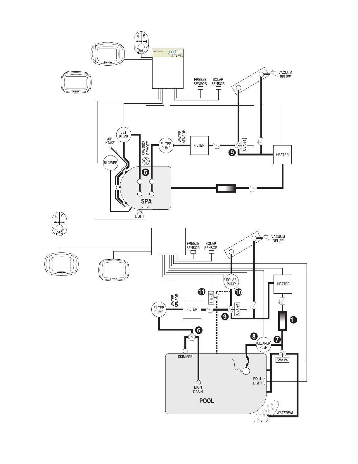
80
INTELLICHLOR® SCG
2
INTELLICHLOR® SCG
Check Valve
Wireless
Transceiver
IntelliCenter
Control System
Outdoor Control
Panel
Wireless Controller
Wireless
Transceiver
Indoor Control Panel
IntelliCenter™ Control System
Load Center with
Outdoor Control Panel
Pool Spa Features Lights
air 77° F
Schedule Usage Chemistry Status
3
3 3
84°
78°
92°
85°
Saturday Jan. 24, 2015 08:00 AM
FRZ ON
Wireless Controller
Indoor Control Panel
Recommended Hydraulic Schematic for Single Body Systems
IntelliCenter Control System Installation Guide IntelliCenter Control System Installation Guide
Page 89

Over-The-Air (OTA) Firmware Updates
The IntelliCenter® Control System can receive firmware updates via your WiFi home wireless router.
When available, firmware updates will automatically be downloaded to the Indoor and outdoor control
panel, wireless remote and Expansion panels in silent mode. Once this process has been completed, in
background while the system is operating, all Sub-Panels will display a message dialog indicating a new
software update is ready to install. See below for more information.
Note: For system firmware versions before version 0.20, be sure to configure (enable) all system
Sub-Panels as described on page 86 to receive over-the-air software updates.
Home Screen (Outdoor Control Panel (OCP) master panel:
Firmware
install icon
When an IntelliCenter Control System firmware update
message dialog is displayed on the panels, it indicates that
the firmware update has been downloaded to the system
and is now ready to install. You can accept or reject the
update:
During the firmware download process to the Outdoor
Control Panel (OCP) master panel, the download
firmware version icon and the completion percentage is
displayed (top right of OCP screen). After the download
process has been competed the following dialog boxes
are displayed.
No: Do not accept the specific firmware update at this time. This update will not occur again until the
next time new a firmware version update is available.
Yes: Accept and start the firmware update for all configured panels. Note: If needed, see page 86
for panel configuration instructions. Note: Pumps and other equipment operating on schedules will
momentary reset after the firmware update is completed.
Firmware
download icon
1.047 10%
1.047 10%
81
Manual Firmware Update Option (USB) Update Later: If you chose not to install the latest firmware
update, you can copy it to a USB device from the outdoor panel and install it onto other panels that are
mismatched and not yet updated.
Download Firmware Updates from: http://www.pentair.com/poolsoftwaredownloads
If you chose not to install the latest firmware update when it was available, you can download the latest
version from the link shown above, then copy it to a USB device from the outdoor panel and install it onto
other Expansion panels that were not updated. Note: If needed, be sure to configure (enable) all system
Sub-Panels. See “Configure Expansion Panel” below.
Page 90

82
Over-The-Air (OTA) Firmware Updates (Panel Mismatch)
Mis-Match Firmware detected (on Sub-Panels): If a Firmware update was unsuccessfully installed on a
sub-panel, a MIS-MATCH message is displayed (“Version Mismatch Detected”) on the panel that does not
match the firmware version on the Outdoor Control Panel (OCP) master panel.
Note: If for example the wireless remote was asleep when a firmware update was attempted, the system
will indicate there is a firmware mis-match between the main OCP and wireless remote.
Firmware Update Dialog Box (manual USB option): From this dialog box update the mismatch panel as
follow:
Download the latest firmware version from: Firmware Updates from http://www.pentair.com/
poolsoftwaredownloads. Copy thsi update file to a USB device.
Tap “Update from USB” to install the latest firmware onto the mismatched panel.
Configure Expansion Panel: Use this option to configure a Sub-Panel that is not configured to accept OTA
firmware updates.
IntelliCenter Control System Installation Guide IntelliCenter Control System Installation Guide
Page 91

Enabling All System Panels (for software versions up to 1.047)
For software versions up to 1.047 the IntelliCenter Control System can receive sofware updates via your
WIFi home wireless router. Sofware updates will automatically occur to the Indoor and outdoor control
panel, wireless remote and Expansion panels in background while the system is operating. Note: to receive
over-the-air software updates, be sure to configure all the system panels as described below:
Enable all System Panels: Outdoor Control Panel (OCP), (Indoor Control Panel (ICP), Expansion Panel (XCP)
and Wireless Control Panel (WCP):
1. Configure the ICP on both OCP and ICP: From the Main Outdoor Control Panel Home
screen, tap Settings > Advanced System Configuration > IntelliCenter Indoor Panel Setup >
Indoor Panel #1 (Repeat if a second ICP (#2) is connected). Repeat this procedure again for
the ICP, starting from the ICP Home Screen. Select Assign this Panel to Indoor Panel #1 (on
the Indoor Panel Enable screen). If configuring a second ICP (#2), then select Assign this
Panel to Indoor Panel #2.
2. Configure the WCP on both OCP and WCP: From the Main OCP Home screen, tap Settings
> Advanced System Configuration > IntelliCenter Wireless Remote Setup. The IntelliCenter
Wireless Remote Setup screen is displayed. Tap Enable Panel (On). Use the Wireless
Channel button to select an address (default is 15). Note: Be sure to match the same
Channel # for the WCP and OCP. Repeat this procedure again for the WCP, starting from
the WCP Home Screen. Note: If the wireless channel number is changed, be sure to
change the Wireless Repeater channel to the same channel number.
83
3. Configure the XCP from the OCP Home Screen (#1, #2, or #3 if system has more than 1
XCP):
a) tap Settings > Advanced System Configuration > Installation Setup > Body Configuration.
b) Select Expansion 1 (disabled) XCP1 (for XCP#1).
c) On the Panel Identification screen, select Enable/Disable and tap the Enable button.
d) Tap the Return button, then select i5x (5 Relays).
e) If the i10x kit is installed, select i10x on the Expansion Panel Daughter Card screen
instead of i5x.
f) On the Expansion Panel Daughter Card screen, tap Return.
4. Configure Expansion Panels (XCP #1, #2, or #3):
a) Tap Settings > Advanced System Configuration > Installation Setup > Body Configuration.
Repeat steps 3a to 3f above, except for 3c:
b) After selecting Enable/Disable select Assign this Panel to Expansion 1 (if this is XCP #1)
and tap the Return button.
c) Repeat Steps 4a to 4b to configure XCP #2 and XCP #3
5. Once all the Panels are configured (enable), check that the system panels have the same
firmware version and are fully functional.
IntelliCenter Control System App: This free app is available for Apple iOS and Android devices.
Important Note: Use following IntelliCenter Firmware V1.040 update instructions for a FIRST TIME SYSTEM
INSTALL or after a SYSTEM FACTORY RESET. Enable all System Panels: Outdoor Control Panel (OCP), (Indoor
Control Panel (ICP), Expansion Panel (XCP) and Wireless Control Panel (WCP): IntelliCenter® CONTROL SYSTEM FIRMWARE V1.040 UPDATE AVAILABLE ONLINE AT: http://www.pentair.com/poolsoftwaredownloads.
Page 92

84
Glossary
The Control Panel: The IntelliCenter® Control System Outdoor Control Panel with flexible hinge.
Installed in upper portion of IntelliCenter Control System Load Center.
EMI (Electromagnetic interference) filter: Protective circuit element that must be used between
the IntelliChlor transformer and supply lines.
Expansion Kit: A kit that includes additional auxiliaries to an existing Personality Kit. Requires a
Load Center or Power Center for each expansion kit.
Feature Circuits: Programmable circuits that may control relays and/or valve actuators. For details,
see the IntelliCenter Control System Systems User’s Guide (P/N 522461)
High V oltage Panel/Compartment: Removable panel for the high voltage compartment of
IntelliCenter Load Center. The high voltage wiring including circuit breakers, relays, GFCI and
optional IntelliChlor transformer/filter.
Indoor Control Panel: This 9 or 13 button remote controller with LCD (liquid crystal display) is
wired to the control circuit board in the IntelliCenter Control System Load Center. The control panel
can be wall mounted inside a house to control the IntelliCenter system.
IntelliChlor
®
(SCG): Salt Chlorine Generator. Uses a process known as electrolysis to produce
sodium hypochlorite (liquid chlorine) from a low concentration of salt added to the pool water.
Model IC 20 Cell (P/N 520554) for pools up to 20,000 U.S. gallons (75 liters) and model IC 40 Cell
(P/N 520555) for pools up to 40,000 U.S. gallons (151 liters). The external IntelliChlor Salt Chlorine
Generator Load Center (P/N 520556).
iS4 Remote Controller: Four function spa-side remote. Spa wall or deck mounted.
Load Center: Metal enclosure with power relays, transformer, and circuit breakers. Used for
distributing power for controlling IntelliCenter Control System. Also known as the sub panel.
Low V oltage Compartment: Top compartment of Load Center or Power Center for all low voltage
wiring.
Low V oltage Raceway: Vertical space in the left side of Power/Load Center for low voltage cabling.
Mud Box: Enclosure to provide mounting features for SpaCommand controller or iS10 spa-side
remote that is cast into gunite, concrete, or other spa wall/deck construction.
Outdoor Control Panel: Control panel with flexible hinge installed in upper portion of Power/Load
Center to control IntelliCenter Control System.
Personality Board: The circuit board mounted on top of the Outdoor Control Panel motherboard.
The Personality board defines the system capabilities.
Personality Kit: Set of parts to define the capability of a system; may include: Outdoor Control
Panel, temperature sensors, actuators, control panel, additional relays, actuators.
Power Center: Same as Load Center with the exception of the circuit breaker base.
Relay Circuits: The circuits that control the relays on the IntelliCenter Control System circuit board.
Salt Chlorine Generator (SCG): Automated pool chlorinator that sanitizes using salt water (see
IntelliChlor Salt Chlorine Generator).
IntelliCenter Control System Installation Guide IntelliCenter Control System Installation Guide
Page 93

Glossary (continued)
Screw T erminal Connector: Removable connector that may attach to circuit board with multiple
sockets to receive conductors from controllers and sensors; conductors held by screw terminals;
multiple conductors of a small enough gauge (usually 22 AWG) may be coupled to a single socket
of a terminal connector.
85
SpaCommand
®
Controller: Up to ten function spa-side remote with temperature changing
capability. Can be spa wall or deck mounted. Connects to the Load center via RS-485 COM port.
Transceiver: Circuit board with attached antenna that can send and receive radio frequency
(wireless) transmissions. Used with QuickTouch
Wireless Controller: Wireless controller for the IntelliCenter
®
II remote, and Wireless Control Panel.
®
Control System with all the
functionality of the Indoor and Outdoor Control Panel. Connects to the Load center via RS-485 COM
port.
Page 94

86
Notes
IntelliCenter Control System Installation Guide IntelliCenter Control System Installation Guide
Page 95

Notes
87
Page 96

88
1620 HAWKINS AVE., SANFORD, NC 27330 • (919) 566-8000
1095
1 WEST LOS ANGELES AVE., MOORPARK, CA 93021 • (805) 553-5000
www.pentair.com
All indicated Pentair trademarks and logos are property of Pentair Inc. or its global aliates in the U.S.A. and/or other countries. Third
party registered and unregistered trademarks and logos are the property of their respective owners
© 2020 Pentair. All rights reserved. This document is subject to change without notice.
*522989*
P/N 522989 Rev. F 12/2020
 Loading...