

Page 1
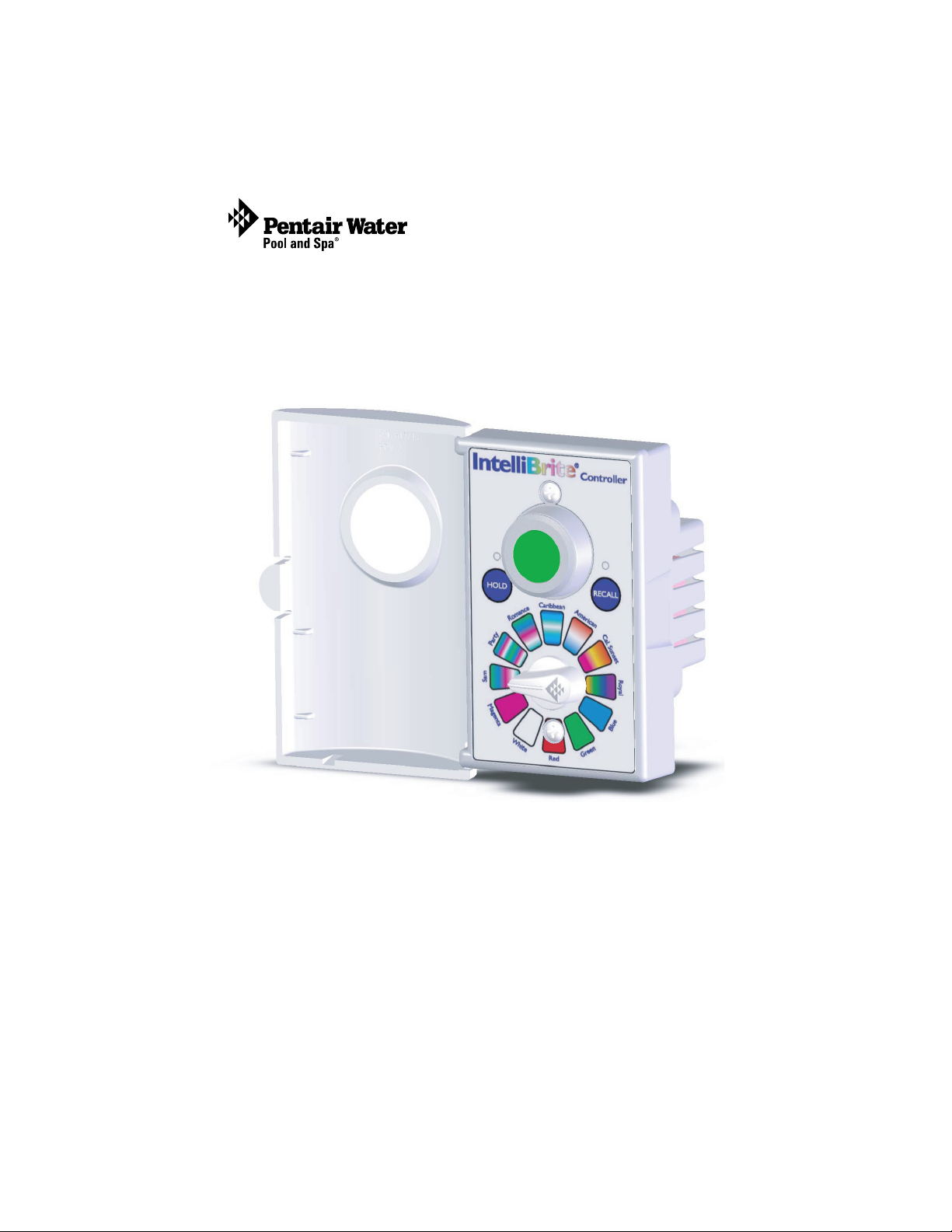
IntelliBrite
(For IntelliBrite Pool, Spa and
Landscape Lighting Fixtures)
®
Controller
Installation and User’s Guide
IMPORTANT SAFETY INSTRUCTIONS
READ AND FOLLOW ALL INSTRUCTIONS
SAVE THESE INSTRUCTIONS
IntelliBrite Controller Installation and User’s Guide
Page 2

i
This product may be protected by the following U.S. patent and all corresponding
foreign conterparts:
US Patents Pending.
© 2009 Pentair Water Pool and Spa, Inc. All rights reserved.
1620 Hawkins Ave., Sanford, NC 27330
(800) 831-7133 • (919) 566-8000
10951 West Los Angeles Ave., Moorpark, CA 93021
(800) 831-7133 • (805) 553-5000
IntelliBrite®, SAm®, IntelliTouch®, EasyTouch®, and Pentair Water Pool and Spa® are
trademarks and/or registered trademarks of Pentair Water Pool and Spa, Inc. and/
or its affiliated companies in the United States and/or other countries. Unless noted,
names and brands of others that may be used in this document are not used to
indicate an affiliation or endorsement between the proprietors of these names and
brands and Pentair Water Pool and Spa, Inc. Those names and brands may be the
trademarks or registered trademarks of those parties or others.
P/N 619751 - Rev C - 07/30/2009
IntelliBrite Controller Installation and User’s Guide
Page 3
WARNINGS AND IMPORTANT SAFETY PRECAUTIONS
IMPORTANT NOTICE
Attention Installer: This manual contains important information
about the installation, operation and safe use of this product.
This information should be given to the owner and/or operator
of this equipment. When installing and using this electrical
equipment, basic safety precautions should always be followed,
including the following:
IMPORTANT SAFETY INSTRUCTIONS PERTAINING TO A
RISK OF FIRE, ELECTRIC SHOCK, OR INJURY TO PERSONS.
READ AND FOLLOW ALL INSTRUCTIONS.
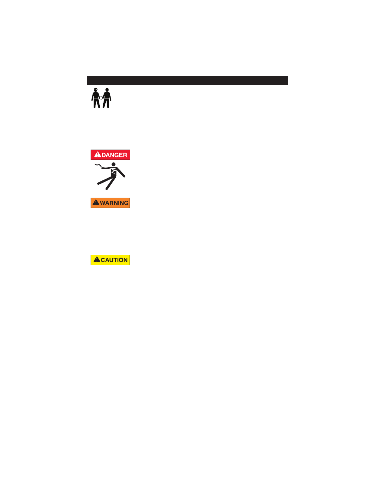
DANGER! RISK OF ELECTRIC SHOCK, WHICH CAN
RESULT IN SERIOUS INJURY OR DEATH. Before
attempting installation or service, ensure that all power to
the circuit supplying power to the system is disconnected/
turned off at the circuit breaker.
Grounding (earth bonding) is required. The IntelliBrite
Controller should be installed by a qualified professional
and grounded.
Read Safety Precautions and Important Instructions.
Before attempting any electrical wiring, be sure to read
and follow Safety Instructions. Wiring should only be
performed by a qualified professional.
Ii
Before installing this product, read and follow all warning
notices and instructions which are included. Failure to follow
safety warnings and instructions can result in severe injury,
death, or property damage. Call (800) 831-7133 for additional
free copies of these instructions.
Do not use this product to control an automatic pool cover.
Swimmers may become entrapped underneath the cover.
IntelliBrite Controller Installation and User’s Guide
Page 4

iIi
WARNINGS AND IMPORTANT SAFETY PRECAUTIONS
Be sure the pool electrical system conforms with all requirements of the
National Electrical Code (NEC), and all local codes and ordinances. A
licensed or certified electrician must install the electrical system to meet or
exceed those requirements before the IntelliBrite Controller is installed. The
electrician should also consult the local building department regarding local
codes. Some of the NEC requirements are listed below:
• The IntelliBrite Controller must be installed by a qualified
electrician, according to the National Electrical Code (including
article 680) or Canadian Electrical Code (including section 68)
and, local code requirements. For Canadian installations, supply
circuit must be protected by a ground fault circuit interrupter.
• The IntellilBrite Controller must be provided with a fail-proof
ground as required by NEC, Article 680 and any applicable local
codes For Canadian installations, the supply circuit must be
protected by a ground fault circuit interrupter.
• Do not install the IntelliBrite Controller within 5 feet (3 meters for
Canadian installations) of any body of water. USE COPPER
CONDUCTORS ONLY.
• The IntelliBrite Controller should be mounted at least 1 foot
above the water and ground level.
• Do not exceed the maximum ratings of individual components,
wiring devices, and current carrying capacity of conductors.
• For grounding and bonding the IntelliBrite Controller and the
installation, refer to section 680 of the National Electrical Code or
section 68 of the Canadian Electrical Code.
• The lighting circuit must have a Ground Fault Circuit Interrupter
(GFCI), and an appropriately rated circuit breaker.
• The light fixture and all metal items within five (5) feet of the pool
must be properly electrically bonded.
• The IntelliBrite Controller must be properly electrically bonded and
grounded.
• Do not submerge the IntelliBrite Controller.
• Do not connect two or more IntelliBrite Controller together.
IntelliBrite Controller Installation and User’s Guide
Page 5

Contents
IntelliBrite Controller Overview ......................................................................... 1
Controls and Buttons ..................................................................................... 1
Selecting a Light Show or Fixed Color ............................................................. 2
Hold and Recall Feature................................................................................... 2
Powering on the IntelliBrite light(s) ................................................................... 3
Troubleshooting ................................................................................................3
Outlet Box Specifications ................................................................................. 3
Installing an Outlet box for the IntelliBrite Controller ...................................... 4
Wiring an IntelliBrite Controller to IntelliBrite LED Lights ............................... 5
12 VAC IntelliBrite LED Landscape Lights ......................................................5
IntelliBrite Controller System Wiring Diagram ................................................. 7
Installing the IntelliBrite Controller in the Outlet box ....................................... 8
Wiring IntelliBrite Landscape LED Lights ........................................................ 9
IntelliBrite Controller kit contents
The following items are included in the IntelliBrite Controller kit:
• IntelliBrite Controller, P/N 600054
• Gasket, P/N 619763
• Knob, P/N 690026
• Door, P/N 690027
• Screw kit, P/N 619764
• Installation and User’s Guide (this manual)
iV
Note: Outlet box purchased separately (see page 3)
Technical Support
Sanford, North Carolina (8 A.M. to 5 P.M. ET)
Moorpark, California (8 A.M. to 5 P.M. PT)
Phone: (800) 831-7133 - Fax: (800) 284-4151
Related manuals - Download the IntelliBrite LED Pool Light Installation and
User’s Guide (P/N 619675) at:
http://www.http://www.pentairpool.com/pdfs/IntelliBritePoolOM.pdf
IntelliBrite Controller Installation and User’s Guide
Page 6

1
IntelliBrite Controller Overview
The IntelliBrite™ Controller provides complete control of Pentair Water Pool
and Spa® IntelliBrite underwater LED (light-emitting diode) lights, and
IntelliBrite LED landscape lights. It’s easy to select a lighting feature, just dial
in any one of the pre-programmed color light shows or fixed colors. Using the
Hold and Recall buttons you can also create endless unique lighting effects.
The IntelliBrite Controller can control individual or multiple IntelliBrite LED
lights. Multiple IntelliBrite LED lights can be connected via a junction box to
an IntelliBrite Controller so that all lights can be switched on and off together.
IntelliBrite LED lights are fully compatible with Pentair IntelliTouch
EasyTouch® automation system. For more information about using IntelliBrite
lights with IntelliTouch systems, refer to the IntelliTouch User’s Guide (P/N
520102) and the EasyTouch User’s Guide (P/N 520584).
The IntelliBrite controller is a 120 VAC device, DO NOT connect
12 VAC IntellilBrite pool/spa LED lights or IntelliBrite LED
landscape lights directly to the IntelliBrite controller, use an appropriate step
down transformer between the controller and lights. For more information see
page 5 - 9.
Controls and Buttons
The IntelliBrite Controller controls, buttons and LEDs are shown below:
®
and
Door
HOLD
button
and
LED
IntelliBrite Controller
IntelliBrite Controller Installation and User’s Guide
Power
ON/OFF Switch
RECALL button
and LED
Color show
Selections
Dial
(for selecting color
light shows and
fixed colors)
Page 7

Selecting a Light Show or Fixed Color
Note: When the IntelliBrite LED light(s) are powered on, a white light will
momentarily illuminate, followed by the selected color, unless the HOLD or
RECALL feature was previously enabled.
To select a color light show mode or fixed color mode, rotate the dial so that it
points to the desired selection.
The color mode selections are described below starting clockwise from the
9 o’clock position:
Light Show Mode
2
• SAm Mode: Cycles through white, magenta, blue and green colors
(emulates the Pentair Water Pool and Spa SAm
®
light).
• Party Mode: Rapid color changing building energy and excitement.
• Romance Mode: Slow color transitions creating a mesmerizing and
calming effect.
• Caribbean Mode: Transitions between a variety of blues and greens.
• American Mode: Patriotic red, white and blue transition.
• California Sunset Mode: Dramatic transitions of orange, red and
magenta tones.
• Royal Mode: Richer, deeper color tones.
Fixed Colors
• Blue: Fixed color.
• Green: Fixed color.
• Red: Fixed color.
• White: Fixed color.
• Magenta: Fixed color.
Hold and Recall Feature
Note: When the IntelliBrite LED light(s) are powered on, a white light will
momentarily illuminate, followed by the selected color, unless the HOLD or
RECALL feature was previously enabled.
Hold button/LED: Press this button (LED on) to capture and save a color
effect while displaying one of the light show modes. When the button is
pressed, the LED will be on, indicating that the color effect is captured.
Recall Button/LED: Use this button (LED on) to activate the last saved
color effect. When the button is pressed, the LED will be on, indicating
that the color effect is being displayed.
IntelliBrite Controller Installation and User’s Guide
Page 8

3
Powering on the IntelliBrite light(s)
When the IntelliBrite LED light is powered on, a momentarily white light
will illuminate, followed by the dial selected color.
Troubleshooting
Use the following tips to help to resolve problems that might occur while
operating the IntelliBrite Controller.
melborPnoitcA/esuaC
.gnihsalferasDELehtfohtoB dedeecxesahdaolehttahtdetcetedsahrellortnoCetirBilletnIehT
.trohsro
.gnihsalfregnolonerasDELehttahterusnE
.etanimullitonlliwthgilehT
.ylreporpnoitcnuftonseodthgiL
gehtkcehC
.rekaerbtiucricniamehtotdna
Outlet Box Specifications (purchased separately)
.yrassecenfiteserdnagniriwtluafdnuor
htotdeilpparewopCAreporpsierehttahteruseB
tuodetrohssituptuoehtroegattawelbawollamumixameht
daolevissecxeevomeR.FFOrellortnoCetirBilletnIehtfohctiwS.1
.tinuehtnorewopothctiwsrewoprellortnoCetirBilletnIehtsserP.2
edisloopehttaxobnoitcnujehtotnoitcennocgniriwthgilehtkcehC
.thgile
The IntelliBrite Controller requires a standard outlet box which is purchased
separately. The outlet box must meet the following specifications:
• Outlet box type: 22.5 cubic inches (minimum) - Suitable for wet
locations with UL/CSA approval listings. Check the inside of
outlet box for specification label.
• A minimum of one 3/4” steel conduit.
4.50”
1.60”
2.75”
Outlet Box (22.5 cubic inches minimum)
IntelliBrite Controller Installation and User’s Guide
Page 9

Installing an Outlet box for the IntelliBrite Controller
The IntelliBrite Controller mounts onto a standard outlet box (22.5 cubic
inches). See page 3 for outlet box specifications.
RISK OF ELECTRICAL SHOCK OR ELECTROCUTION
TURN power OFF at circuit breaker - Always
disconnect power to the pool light at the circuit
breaker before servicing the light. Failure to do
so could result in death or serious injury to
installer, service person, pool users, or others due
to electrical shock.
To install the outlet box:
1. Position the IntelliBrite Controller and outlet box to meet National
Electrical Code requirements, and to prevent hazard to personnel.
2. Run conduit from the IntelliBrite light niche to the junction box.
Note: The outlet box must be located a minimum distance of five (5)
feet measured horizontally from the inside wall of the pool and not
less than one (1) foot above the maximum pool water level
measured to the top of the outlet box.
3. Remove the lower conduit plug from the outlet box.
4. Mount the outlet box onto the conduit.
4
Lower
Outlet Box
IntelliBrite Controller Installation and User’s Guide
conduit
plug
Page 10

5
Wiring an IntelliBrite Controller to IntelliBrite LED Lights
Maximum wattage when using multiple lights with controller
When using multiple IntelliBrite LED lights, the total allowable light wattage is
300 Watts maximum. The following example combination of IntelliBrite LED
lights can be connected to the IntelliBrite Controller:
• Two (2) IntelliBrite LED pool lights (each light 70 Watt maximum)
• One (1) IntelliBrite LED spa light (40 Watt maximum)
• Eight (8) Landscape LED lights (each light 15 Watt maximum)
RISK OF ELECTRICAL SHOCK OR ELECTROCUTION
TURN power OFF at circuit breaker - Always
disconnect power to the pool light at the circuit
breaker before servicing the light. Failure to do
so could result in death or serious injury to
installer, service person, pool users, or others due
to electrical shock.
To wire multiple 120 Volt IntelliBrite LED Lights to an IntelliBrite Controller:
1. Route the IntelliBrite LED Light cord and the three wires (white,
green and black) from the GFCI, up through the conduit opening,
and into the outlet box.
2. Strip the ends of the three light conductors, and the three GFCI
Note: Use underwater lights with water resistant cord only.
wires.
3. Using the ground screw in the outlet box, secure the green ground
wire from the light, and the GFCI to the back of the outlet box.
4. Connect the red wire from the Controller, to the red wire, which is
attached to the black wire of the light at the junction box.
5. Connect the white wire from the Controller to the white wire from
the light cord, and the white wire from the GFCI (neutral).
6. After the wiring has been completed and checked, proceed to
“Installing the Controller in the Outlet Box” on page 10.
12 VAC IntelliBrite LED and Landscape Lights
IMPORTANT! When installing 12 VAC IntelliBrite LED and Landscape lights,
connect the lights to the secondary 12 VAC output of the step down
transformer, then connect the IntelliBrite controller to the 120 VAC primary
input of the step down transformer.
IntelliBrite Controller Installation and User’s Guide
Page 11

6
BLACK
(INTELLIBRITE
CONTROLLER)
RED
(INTELLIBRITE
CONTROLLER)
WHITE
(INTELLIBRITE
CONTROLLER)
WHITE
(NEUTRAL)
WHITE
(NEUTRAL)
BLACK
(HOT)
CONNECTION TO THE
LIGHT’S BLACK WIRE
OR 12 VAC Transformer
(SWITCHED HOT)
GROUND
GROUND CONNECTION
TO THE JUNCTION BOX
BLACK
(HOT)
WHITE
(NEUTRAL)
GREEN
(GROUND)
From GFCI or
Transformer
GROUND
BLOCK
NEUTRAL
BLOCK
THREE
LIGHT
WIRES
SWITCHED HOT
FROM THE
INTELLIBRITE
CONTROLLER
Wiring Diagram
(from Light to Junction Box
and GFCI or Transformer)
IMPORTANT! When installing 12 VAC IntelliBrite LED and Landscape lights,
connect the lights to the secondary 12 VAC output of the step down transformer,
then connect the IntelliBrite controller to the 120 VAC primary input of the step
down transformer.
IntelliBrite Controller Installation and User’s Guide
Page 12

7
LIGHTS
GND
HOT
J-BOX
GND
HOT NEUTRAL GND
AC POWER (CIRCUIT BREAKER)
NEUTRAL
NEUTRAL
SWITCHED HOT WIRE
OPTIONAL GND
CONDUIT
(or RIGID)
PVC
OUTLET BOX
22.3 CU. INCHES MINIMUM
IntelliBrite Controller
FRONT
IntelliBrite Controller Installation and User’s Guide
HOT
POWER CIRCUIT
BOARD
CONTROL
PANEL
NEUTRAL
FUSE
SWITCHED HOT WIRE
IntelliBrite Controller System Wiring Diagram
GND
METAL OUTLET BOX ONLY
Page 13

Installing the IntelliBrite Controller in the Outlet box
The IntelliBrite Controller mounts onto a standard outlet box (22.5 cubic
inches minimum). See page 3 for outlet box specifications.
After wiring the IntelliBrite Controller, check all wiring connections before
mounting the controller into the outlet box.
To install the IntelliBrite Controller:
1. Neatly arrange the wires in the back of the outlet box.
2. Align the Controller with the screw holes of the outlet box. Secure
the Controller to the outlet box with the two (2) retaining screws.
3. Close the front door of the Controller.
Arrange
wires neatly
behind
Controller
8
Retaining
Screw
Retaining
Screw
Screw hole
Screw hole
Retaining Screw
Retaining Screw
IntelliBrite Controller Installation and User’s Guide
Page 14

9
WIRING INTELLIBRITE LANDSCAPE LED LIGHTS
Using the IntelliBrite Controller to control IntelliBrite
landscape LED lights
Using an IntelliBrite® Controller (p/n 600054, sold separately) to operate the
IntelliBrite® landscape LED lights makes it easy to dial in any of the various
color light shows or fixed color. The controller’s Hold and Recall buttons also
allows you to create endless unique lighting effects. The IntelliBrite® Controller can control individual or multiple IntelliBrite® LED landscape lights.
Multiple IntelliBrite® landscape lights can be connected via a junction box to
the IntelliBrite® Controller so that all lights can be switched on and off
together.
Maximum wattage when using multiple IntelliBrite LED lights
with the IntelliBrite Controller
When using multiple IntelliBrite LED lights, the total allowable light wattage is
300 Watts maximum. The following example combination of IntelliBrite LED
lights can be connected to the IntelliBrite Controller:
• Two (2) IntelliBrite LED pool lights (each light 70 Watt maximum)
• One (1) IntelliBrite LED spa light (each light 40 Watt maximum)
• Six (6) IntelliBrite LED landscape lights (each light 20 Watt maximum)
Wiring the IntelliBrite Controller to a 12 VAC Transformer
The following diagram shows how to connect the IntelilBrite LED lights to a
120 VAC wall outlet using a 12 Volt transformer.
wire nut
GREEN
WHITE
BLACK
Extension cord
IntelliBrite Controller
BLACK
RED
GREEN
WHITE
BLACK
WHITE
Intermatic
AC Power cord
12 Volt
Intermatic
Transformer
12O VAC
GFCI Wall
IntelliBrite
Controller
Outlet
IntelliBrite Controller Installation and User’s Guide
Page 15

NOTES
10
IntelliBrite Controller Installation and User’s Guide
Page 16

*619751*
P/N 619751 - Rev C
IntelliBrite Controller Installation and User’s Guide
 Loading...