

Pentair HYPRO 9910-D70, HYPRO 9910-D115GR3, HYPRO 9910-D115, HYPRO 9910-D70GR, HYPRO 9910-D160 Installation, Operation, Repair And Parts Manual
...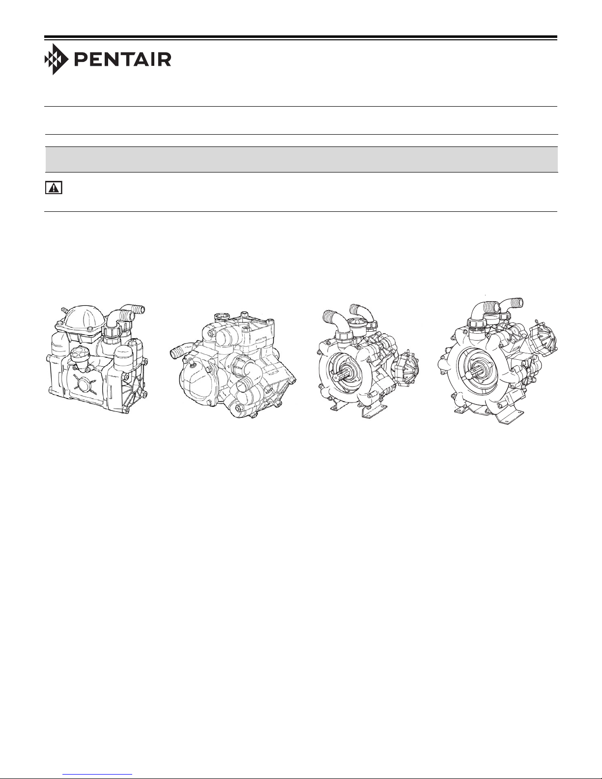
Low Pressure Diaphragm Pumps
HYPRO
®®
Installation, Operation, Repair and Parts Manual
Description
California Proposition 65 Warning -- This product and related accessories contain chemicals known to the
State of California to cause cancer, birth defects or other reproductive harm.
Hypro low pressure diaphragm pumps are recommended
for ground and low-level spraying of herbicides,
pesticides, liquid fertilizers and many other hard-tohandle fluids. Low-cost maintenance and almost wearfree operation make these pumps ideal for a wide variety
of spraying jobs. Pressure and output are designed for
optimum performance of medium to large-sized sprayers.
Hypro low pressure diaphragm pumps can be adapted for
splined shaft, hollow shaft, and solid shaft drive options.
Pumps include a pulsation dampener.
Form L-1381
Rev. C
Model 9910-D70
Model 9910-D70GR
Max flow: 19 gpm
Max pressure: 290 psi
2 diaphragms
Model 9910-D115
Model 9910-D115GR34
Max flow: 30.1 gpm
Max pressure: 290 psi
3 diaphragms
Model 9910-D135
Max flow: 34.8 gpm
Max pressure: 290 psi
3 diaphragms
Model 9910-D160
Max flow: 42.5 gpm
Max pressure: 290 psi
4 diaphragms
Model 9910-D250
Max flow: 66 gpm
Max pressure: 290 psi
6 diaphragms
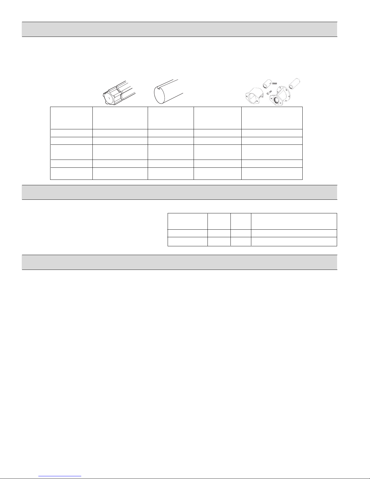
Drive Options
Order appropriate Shaft Adapter Kit for drive option
requirements. Refer to adjoining chart for proper
selection. For proper installation, refer to Page 5.
NOTE: Model 9910-D135 is supplied with a 1-3/8" male
PTO splined shaft as standard. Models 9910-D160 and
Pump 1-3/8" Male 1" Solid Shaft 1-3/8" Female Hydraulic
Model Splined PTO w/Keyway Splined PTO Motor Mounting
Shaft Coupler Flange Kits
9910-D70 9910-KIT1710 9910-KIT1711 9910-KIT1708 9910-HYD2495
9910-D115 9910-KIT1710 9910-KIT1711 9910-KIT1708 9910-HYD2495
9910-D135 Std. 1-3/8"
male-splined shaft N/A N/A N/A
9910-D160 Std. thru shaft N/A N/A 9910-HYD1570
9910-D250 Std. thru shaft N/A N/A 9910-HYD1570
Control Units
Control units are available for easy flow and pressure
control of your spraying system. These units include
a pressure relief valve to control pressure, an oil-filled
pressure gauge to monitor pressure, and multiple outlet
shut-off valves to control boom flow. Refer to the
adjoining chart to select the proper control unit for
your pump.
9910-D250 are supplied with a splined thru shaft. These
models can be adapted for belt and pulley drive with the
use of a split taper bushing (Hypro part number 3115-
0011). Use of this bushing allows a Browning Q2 sheave
to be mounted on the bushing.
Control Max Max
Unit Model GPM PSI
3300-0087 42.5 290
3300-0088 42.5 290
Type
D70, D115, D135, D160, D250
D70, D115, D135, D160, D250
General Safety Information
1. Use of a pressure relief device on the discharge side of pump
is required to prevent damage from pressure build up if the
discharge is closed or blocked while the power source is still
running.
2. WARNING: DO NOT pump flammable or explosive fluids
such as gasoline, fuel oil, kerosene, etc. DO NOT use in
explosive atmospheres. The pump should be used only
with liquids that are compatible with the pump
component materials. DO NOT pump asphalt, asphalt
sealer, roofing compounds, concrete sealers or any twostep curing products. Personal injury may result, and the
warranty will be void. If there are any questions, call the
Hypro Applications toll-free number: 800-445-8360.
3. Do not operate pump above recommended rpm.
4. Do not pump at pressures higher than the maximum
recommended pressures for the pump (see Specifications).
5. Operate pump between temperature range of 45˚ to 140˚ F.
6. Make certain that the power source conforms to the
requirements of your equipment.
7. Provide adequate protection in guarding around the moving
parts, such as the shaft and pulleys.
8. Disconnect power before servicing.
9. Release all pressure within the system before servicing any
component.
10. Drain all liquids from the system before servicing.
11. Secure the discharge lines before starting the pump. An
unsecured discharge line may whip, causing personal injury
and/or property damage.
12. Check hoses for weak or worn condition before each use.
Make certain that all connections are tight and secure.
13. Periodically inspect the pump and the system components.
Perform routine maintenance as required (see Maintenance
section).
14. When wiring an electrically-driven pump, follow all electrical
and safety codes, as well as the most recent National
Electrical Code (NEC) and the Occupational Safety and
Health Act (OSHA).
15. WARNING: Because of the risk of electrical shock, all
wiring should be done by a qualified electrician.
WARNING: DO NOT handle a pump or pump motor with
wet hands, when standing on a wet or damp surface, or
while standing in water.
16. Do not operate a gasoline engine in an enclosed area. Be
sure the area is well ventilated.
17. Use only pipe, hose and fittings rated for maximum rated
pressure of pump or pressure at which pressure relief valve is
set at. Check with local supplier for proper pressure rating. Do
not use used pipe!
18. Do not use these pumps for pumping water or other liquids for
human or animal consumption.
2
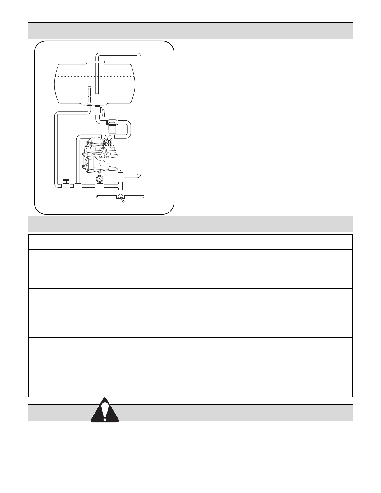
Diaphragm
Pump Connection
Agitator
Tank
Shut-off
Installation
1. Always mount the pump with oil sight tube in the upright
position.
2. Proper selection of type and size of hose is vital to good
performance:
a. Use suction line of spiral wire braid reinforced suction
hose to prevent collapse. Diameter of inlet hose
should be at least that of the pump inlet hose barb or
greater.
Agitation Line
Pressure
Gauge
Control
Valve
To Spray Gun
Boom Shut-off
or Selector
Symptom
The pump does not draw water.
The liquid flow is irregular.
Bypass Line
Pump
Relief Valve
To Boom Nozzles
b. Use only approved high pressure hose on discharge
side of pump.
3. All ports are provided with hose barb connections. Use
good quality hose clamps, and tighten securely.
NOTE: Use only pipe, fittings, accessories, hose, etc.
rated for the maximum pressure rating of the pump.
Troubleshooting
Probable Cause(s)
One or more valves are seating
improperly.
Suction line is plugged or
collapsed. Clogged strainer.
The charge in the pulsation
damper is incorrect.
One or more valves are seating
improperly.
Corrective Action
Remove valve and check
for debris.
Examine suction line.
Clean strainer.
Check pressure in pulsation
dampener (20% working pressure).
Remove valve and check for
debris. Examine the valve seatings
and clean them.
Output drops and the pump is noisy.
Oil comes out of the discharge port
or oil is a milky color.
1. Always drain and flush pump before servicing or
disassembling for any reason (see instructions).
2. Always drain and flush pumps prior to returning unit
for repair.
3. Never store pumps containing hazardous chemicals.
Oil level is too low.
One or more diaphragms split.
Hazardous Substance Alert
4. Before returning pump for service/repair, drain out all
liquids and flush unit with neutralizing liquid. Then, drain
the pump. Attach tag or include written notice certifying
that this has been done. Please note that it is illegal to
ship or transport any hazardous chemicals without United
States Environmental Protection Agency Licensing.
3
Add oil to correct level (halfway up
the sight tube).
Remove manifold and heads. Drain
oil and clean crankcase of water.
Replace diaphragms, heads and
manifold. Refill with Hypro Oil
(Part No. 2160-0038).
Maintenance Instructions for All Models
Maintenance
1. After use, flush the pump with clean water.
2. Hypro diaphragm pumps come with oil in the
crankcase. Hypro recommends changing oil after
40 hours of break-in operation and every three
months or 500 hours, whichever comes first. Use
Hypro Oil (Part Number 2160-0038). Hypro Oil is a
specially formulated, high-grade, nondetergent, SAE
30 weight oil designed to prolong pump life.
To drain oil from the pump, remove the oil drain plug,
and rotate the shaft until the oil stops flowing out. To
fill the pump with oil, slowly pour the oil into sight
tube while turning the pump shaft. Turning the pump
shaft purges all the air out of the crankcase. Always
change oil when replacing diaphragms.
3. For winter storage or if a freezing condition will be
encountered, flush pump with a 50/50 mixture of
water and antifreeze.
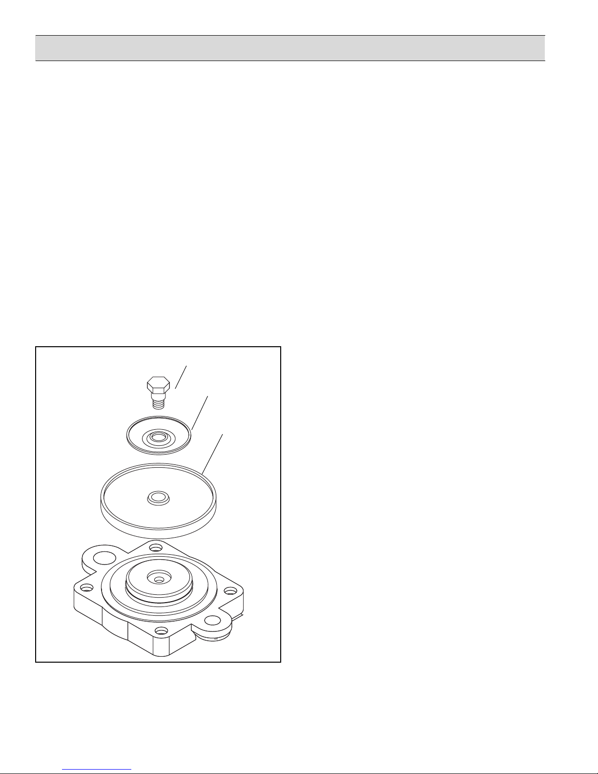
Bolt
Washer
Diaphragm
Diaphragm and Valve Replacement
I. Valve and O-Ring Replacement
1. Occasionally debris can cause the valves to not
seat properly or damage the o-rings. To check
for this problem, follow these steps.
2. Remove the pump manifold. (See parts list for
your model.) Use a 17 mm box wrench (or
adjustable wrench) to remove manifold nuts.
(Use a 13 mm for Models D160, D250.) With
manifold removed, valves can readily be
removed and checked for debris or wear. To
replace valves or o-rings, refer to parts list for
appropriate kits.
II. Diaphragm Replacement
Hypro recommends changing diaphragms every 500
hours or three months, whichever comes first.
1. Drain the oil from the pump by removing drain
plug. Rotate the shaft to remove excess oil.
2. Remove the pump manifold according to Step 2
in Section I: Valve and O-ring Replacement.
3. Use a 19 mm box wrench (or adjustable wrench)
to remove the diaphragm retaining bolt, support
washer and diaphragm. To replace the
diaphragms, order the appropriate repair kit.
See the parts list.
Figure 1. Diaphragm Replacement
4. Turn the crankshaft to bring the piston to its
upstroke to replace the diaphragm. Use the
downstroke to seat the new diaphragm into the
sleeve groove. Install retaining washer and
tighten nut.
5. Replace the pulsation dampener diaphragm by
first bleeding the air from the dampener. (See
parts list for your model.) Use a 13 mm box
wrench to remove the bolts holding the
dampener assembly together, then replace
diaphragm. Recharge dampener to 20% of
operation pressure.
6. Refill crankcase with Hypro Oil (Part No. 2160-
0038). Rotate the shaft slowly forward and
reverse to distribute oil, and fill to the proper
level.
4
17
Parts List for 9910-KIT1708, 9910-KIT1710 and 9910-KIT1711
2
7
8
11
1
12
15
13
14
9
10
Included in
KIT1710
2
3
4
16
5
6
4
3
9
10
1
5
9
9
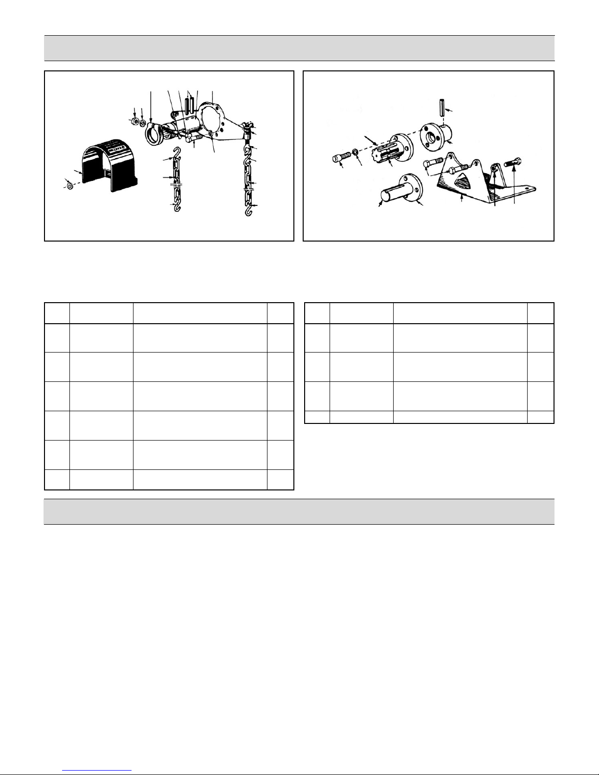
Figure 2. Coupler Kit 9910-KIT1708 Installation
9910-KIT1708: 1-3/8" Female PTO Adapter, Safety
Shield, Torque Arm and Chains
Parts List for 9910-KIT1708
REF. PART DESCRIPTION QTY.
NO. NUMBER REQ’D
1 9910-380271 Torque Arm 1
2 9910-550290 Roll Pin 2
3 9910-320130 Nut 1
4 9910-320131 Washer 1
5 9910-500160 Collar 1
6 9910-500171 Lock Retaining Washer 1
7 9910-320170 12MAx75 Bolt 1
8 9910-550250 Female Splined Shaft 1
9 9910-320650 Chain “S” Hook 4
10 9910-320640 Chain 2
11 9910-620472 M10 x 20 Bolt 2
12 9910-200231 Washer 5
13 N/A Washer (7/16”; 10.5 mm) 1
14 N/A Eye Bolt 1
15 9910-320610 Wing Nut 1
16 2840-0028 Safety Shield (with KIT1708) 1
17 2270-0004 Washer 4
Included in
KIT1711
6
7
9
8
Figure 3. Coupler Kit 9910-KIT1710 Installation
9910-KIT1710: 1-3/8" Male PTO Shaft and Base Kit
9910-KIT1711: 1" Solid Shaft and Base Kit
Parts List for 9910-KIT1710 & 1711 Shaft Kit
REF. PART DESCRIPTION QTY.
NO. NUMBER REQ’D
1 9910-550290 Roll Pin 2
2 9910-620470 M10 x 20 Bolt 3
3 9910-200231 Washer 3
4 9910-620240 1-3/8" Male 6 Spline PTO Shaft 1
5 9910-550510 Adapter 1
6 9910-621600 1" Solid Shaft 1
7 9910-580080 Base 1
8 9910-180150 Nut 1
9 9910-540300 10MAx30 Bolt 1
10 9910-620472 M10 x 20 Bolt 2
Shaft Adapter Kit Installation
Order appropriate shaft kit according to chart on page 2.
Female Splined Coupler Kit 9910-KIT1708 (see Fig. 2).
To install the 1-3/8" female splined shaft coupler:
1. Place the torque bracket (Ref. 1) onto pump and
secure with bolts (Ref. 11).
2. Slide female coupler (Ref. 8) onto pump shaft. Align
holes in coupler with holes in pump shaft and press
in pins (Ref. 2).
3. Make sure clamp (Ref. 5) is over groove in the
coupler. Slide the pump onto the PTO shaft of
power source and tighten clamp.
4. Attach chains (Ref. 10) to tractor to prevent rotation
of the pump.
Solid Shaft Kit 9910-KIT1711, Male Splined Shaft Kit
9910-KIT1710 (see Fig. 3).
To install the 1-3/8" male splined shaft coupler:
1. Slide shaft adapter flange (Ref. 5) over pump shaft.
Align adapter hole with hole on the pump shaft and
press in pin (Ref. 1).
2. Bolt shaft adapter (Ref. 4 or 6) onto flange with three
bolts (Ref. 2) and washers (Ref. 3).
3. Place base (Ref. 7) on pump, and secure with bolts
and washers. Secure opposite side of base with bolt
(Ref. 9) and nut (Ref. 8).
5
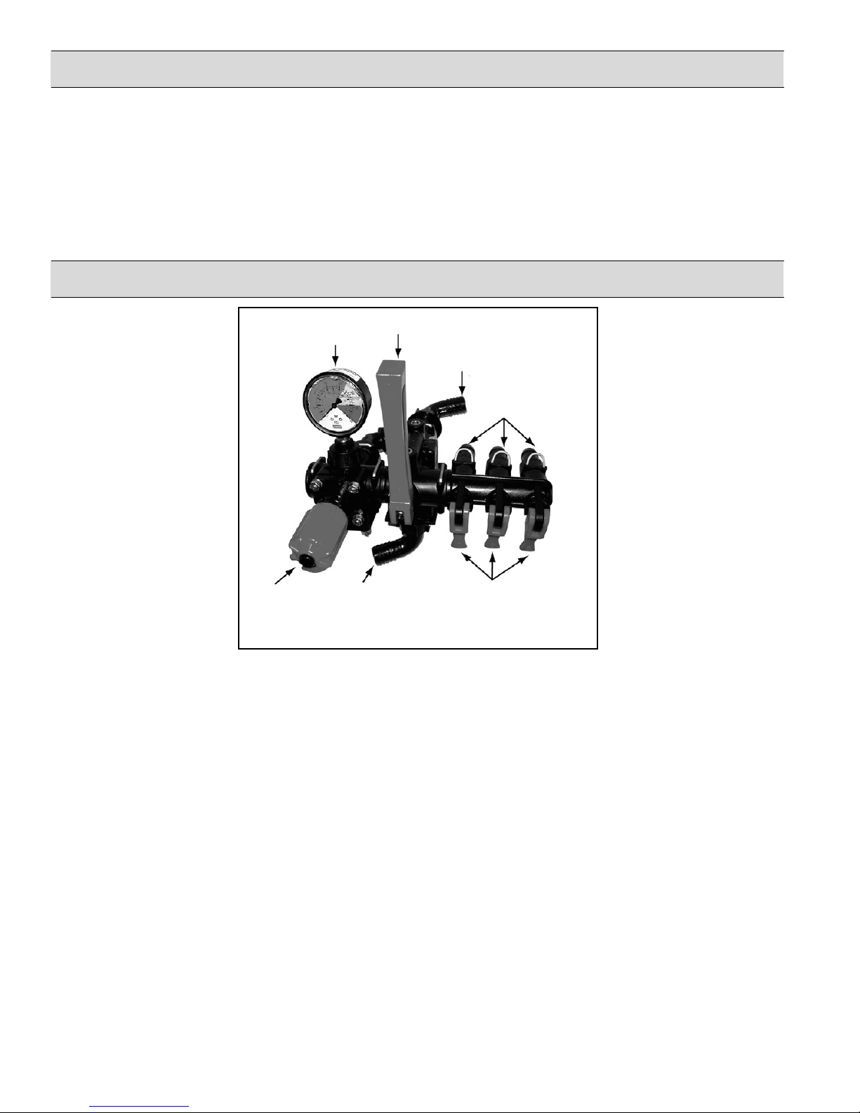
Control Units 3300-0082, 3300-0087 and 3300-0088
Description
The 3300-0087 and 3300-0088 control units are
designed for the control of pressure and output from 0 to
290 PSI. They are supplied with mounting brackets for
mounting separately from the pump. They consist of a
main pressure regulating valve and 3 on-off outlet valves.
For individual boom section control, model 3300-0088
includes a main on-off lever that can be put in the off
position for complete bypass to the tank.
Installation and Operation
6. Main
Pressure Gauge
On-Off Lever
Safety Note: Main relief valve bypass must be
connected to the tank directly without restrictions (such
as ball valves).
2. Main Bypass
3. Outlets
to Boom
Sections
Pressure
Adjustment Knob
1. Main Inlet
5. Outlet Valve Levers
Figure 5. Model 3300-0087 and 3300-0088
flush with clean water.
Model 3300-0087 and 3300-0088 Installation
Locate mounting bracket and secure in desired position. The
pressure line from the pump is connected to main inlet hose
barb (1). The return line is connected unrestricted to the main
bypass hose barb (2). Boom sections are connected to the outlet
boom hose barb (3).
Operation
1. Before starting pump, adjust relief valve for the lowest
possible pressure by screwing the pressure adjustment knob
(4) all the way counterclockwise.
2. On Model 3300-0088, turn the main on-off lever (6) to the full
bypass (up) position.
3. Open all boom feed lines by lifting lever(s) to the up position.
4. Start pump and allow liquid to flow through the control unit.
5. Turn main on-off valve lever (6) to on position (down) and
adjust to the desired spraying pressure by turning the
pressure adjustment knob (4). Turning the knob clockwise
will increase the pressure.
6. The 3300-0087 or 3300-0088 control unit is now ready for
use. After each use, flush the unit with water. For extended
or winter storage, drain the unit completely.
6
 Loading...