

Page 1

IGNITION CONTROL MODULE (ICM) REPLACEMENT KIT
USA (P/N 476224) AND AUSTRALIA (P/N 476223)
FOR MASTERTEMP® AND MAX-E-THERM® POOL AND SPA HEATERS
INSTALLATION INSTRUCTIONS
FAILURE TO FOLLOW ALL INSTRUCTIONS AND WARNINGS CAN RESULT IN SERIOUS BODILY INJURY OR DEATH. THIS PRODUCT SHOULD BE
INSTALLED AND SERVICED ONLY BY A QUALIFIED POOL SERVICE
PROFESSIONAL. INSTALLERS, POOL OPERATORS AND OWNERS MUST READ
THESE WARNINGS AND ALL INSTRUCTIONS IN THE HEATER
INSTALLATION AND USER’S GUIDE BEFORE USING THIS PRODUCT.
THESE INSTRUCTIONS MUST BE LEFT WITH THE POOL OWNER.
Pentair Water Pool and Spa heater related products are available at:
https://www.pentair.com/en/products/pool-spa-equipment/pool-heaters.html
Call (800) 831-7133 for additional free copies of these instructions.
IMPORTANT SAFETY INSTRUCTIONS
READ AND FOLLOW ALL INSTRUCTIONS - SAVE THESE INSTRUCTIONS
Fenwal® Ignition Control Model (ICM)
The following instructions describe how to replace an existing Ignition Control Module (ICM) into a
MasterTemp or Sta-Rite pool and spa heater (USA and Australia models) that doesn’t have RS-485
communication capability.
Contents
ICM Replacement (USA) page 2-5
ICM Replacement (Australia) page 6-9
P/N 476249.A 9/2020
1
Page 2
HEATER ICM REPLACEMENT INSTRUCTIONS (USA)
P/N 476223 Parts List
P/N Description Qty.
476221 ICM F/FLAME SENSE DOM 1
476206 ADAPT 6 PIN FOR DOM ICM AFTR RS485 1
476208 ADAPT F1-F2 FOR DOM ICM AFTER RS485 1
476202 ADAPT 5PIN FOR DOM ICM AFTER RS485 1
476213 LED WIRE ADAPTER 1
476249 INSTALLATION INSTRUCTIONS 1
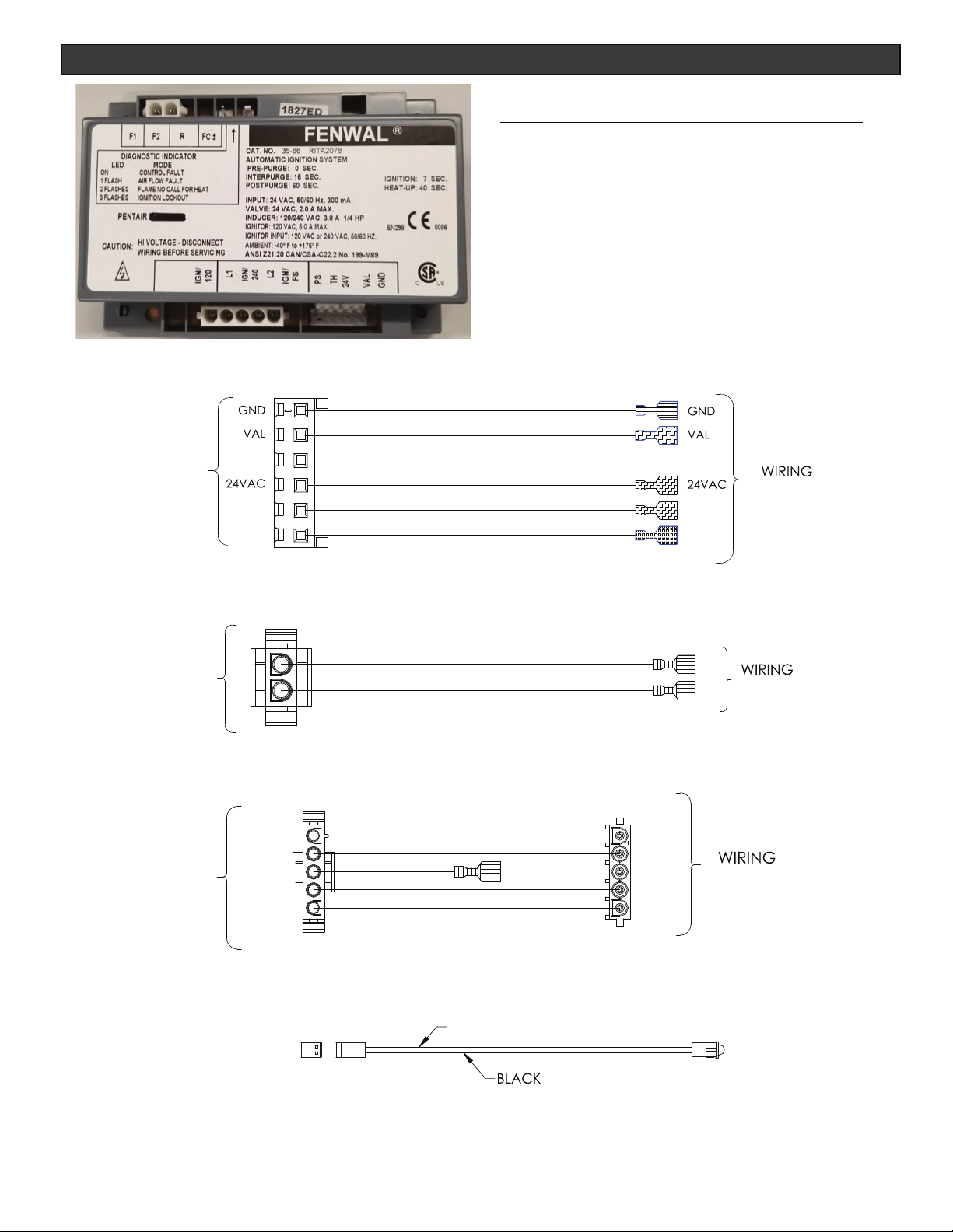
ICM Fenwal
®
(USA) P/N 476221
ICM
FENWAL
ICM
FENWAL
F2
F1
N/A
IND
TH
P/N: 476206
P/N: 476208
IND
TH
F2
F1
HARNESS
HARNESS
ICM
FENWAL
FENWAL
ICM
S2
L2
S1/240
L1
S1/120
S2
L2
S1/240
N/A
L1
S1/120
HARNESS
P/N: 476202
RED
2 1
P/N: 476213
2
Page 3
HEATER ICM REPLACEMENT INSTRUCTIONS (USA)
FIGGGGG. 3
. 3
. 3. 3
. 3aa
a
33. 3
. 3333b
. 44. 4
. 4
scscwswsws
.
.
When installing this kit, basic safety precautions should always be followed. Read and follow all instructions.
Required installation tools:
• Powered socket/nut driver
• 1/4” nut driver bit
• 5/16” socket and nut driver
• 3/8” nut driver
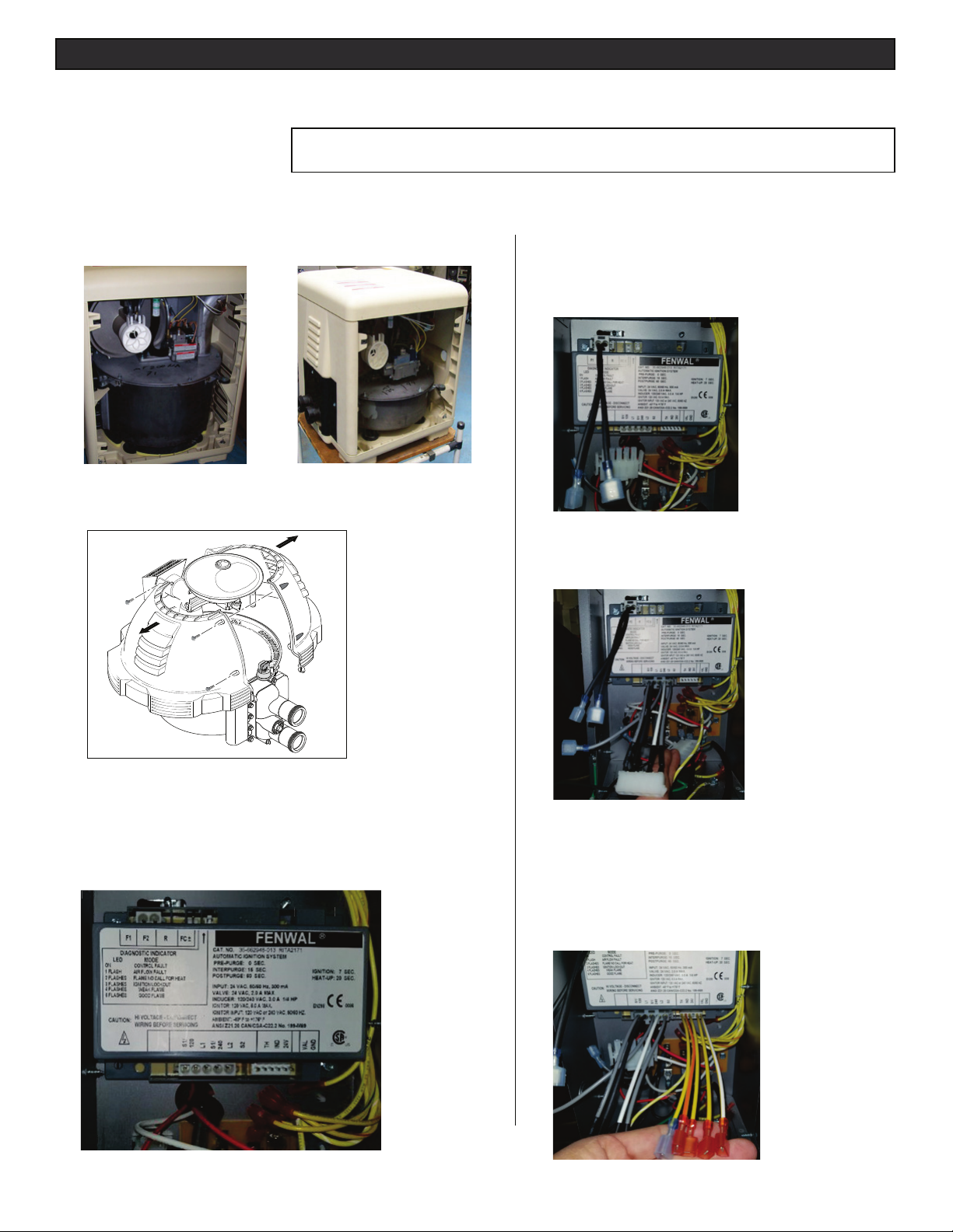
To replace the ICM on a MasterTemp® or Max-E-Therm® Heater:
1. MasterTemp Heater: Remove left side panel from the heater (Fig. 1
and Fig. 2).
CAUTION!: Before unplugging ICM connector plugs, be sure to match
the wire label on both the existing and replacement wire harnesses.
5. Connect the ICM to wire adapter (P/N 476208) for F1
and F2 as shown in Fig. 5. One end of the adapter is
a two position Molex
ICM. The other end of the adapter is a ¼” male quick
connect terminal.
F1/F2
WIRE
ADAPTER
®
connector that connects to the
FIG. 1.
MasterTemp
STD Heater
FIG. 2.
MasterTemp 125 Heater
2. Max-E-Therm Heater: Remove the four (4) bolts from the heater
jackets. Remove, see Fig. 3.
FIG. 3.
Max-E-Therm Heater
3. LEGACY ICM (P/N 42001-0100): Disconnect all connector
plugs and wires from the legacy ICM. Remove the two (2)
mounting screws from the legacy ICM. Remove the legacy ICM
unit from the heater.
4. Install the ICM (P/N 476221): Install the ICM into the heater
Junction Box compartment. Secure the unit with the two (2)
screws.
FIG. 3a
FIG. 3b
FIG. 5.
6. Connect the wire adapter (P/N 476202) with five
position connector housing to the ICM (see Fig. 6).
Leave the female connector header on the other end.
FIG. 6.
7. Connect the last wire adapter (P/N 476206) to the
lower right side of the ICM (see Fig. 7.). Notice that
the new ICM no longer has the 24V or R connection
of the ICM in the upper left side. The 24 V is now in
the multi pin connector header. Additionally, one
location of the multi-pin connector is not in use,
which is in between 24V and VAL.
FIG. 4
FIG. 4.
FIG. 7.
3
Page 4
HEATER ICM REPLACEMENT INSTRUCTIONS (USA)
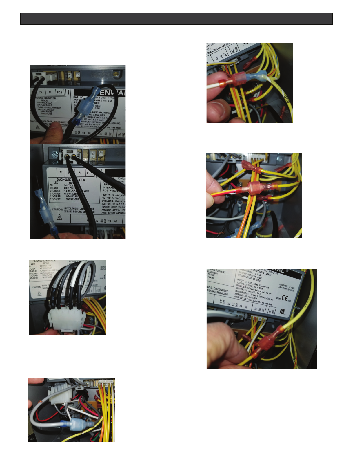
Now that the wire adapters are connected to the ICM.
Proceed connecting each end of the wire adapters to
the existing wire harness as follow:
8. Connect the male terminals from F1 and F2 to the corresponding F1 and F2 cables of the wire harness as
shown in Fig. 8 and Fig. 9.
11. Connect the yellow/white wire coming from GND in the
ICM to the GND cable as shown in Fig. 12.
FIG. 12.
FIG. 8.
FIG. 9.
9. Connect the Molex connector as shown in Fig. 10. Be
sure the two end flat connections mate properly.
12. Connect the red/yellow wire coming out of the multi-pin
connector to the red/yellow wire coming from the PCBA
as shown in Fig. 13.
FIG. 13.
13. Connect the yellow wire labeled 24V from the multi-pin
connector to the yellow wire labeled 24V coming from
the PCBA as shown in Fig. 14.
FIG. 10.
FIG. 10.
10. The new ICM does not have a 240-spade terminal; this
connection is now in the middle of the Molex connector.
The wire adapter has a cable coming out of the Molex that
needs to be connected to the 240 gray cable as show in
Fig. 11.
FIG. 11.
FIG. 14.
FIG. 7.
14. Reassemble the heater control panel assembly. Be
sure that the control panel can be adjusted without
having to lean over the exhaust vent.
4
Page 5

HEATER ICM REPLACEMENT INSTRUCTIONS (USA)
14. Connect the Orange/yellow wire labeled IND to the
Orange/yellow wire labeled IND that comes from the
PCBA as shown in Fig. 15.
FIG. 15.
16. Connect the Red and Black cable from the PCBA to
the ICM if you have the Flame sense cable. Otherwise, connect the wire adapter 476213 with Red
and Black cable and LED to the ICM as shown in
Fig 17.
15. Connect the Blue/Yellow wire labeled TH to the
Blue/Yellow wire labeled TH that comes from the
PCBA as shown in Fig. 16.
FIG. 16.
FIG. 17.
5
Page 6

HEATER ICM REPLACEMENT INSTRUCTIONS (AUSTRALIA)
P/N 476224 Parts List
P/N Description Qty.
476222 ICM W/ FLAME SENSE AUS 1
476207 ADAPT 5 PIN FOR AUS ICM AFTER RS485 1
476213 ADAPTER LED WIRE ADAPTER 1
476249 INSTALLATION INSTRUCTIONS 1
ICM Fenwal
ICM
FENWAL
®
(Australia) 2020 P/N 476222
S1/120
L1
N/A
L2
S2
ICM
FENWAL
S1/120
L1
HARNESS
L2
S2
P/N: 476207
RED
2 1
P/N: 476213
6
Page 7

HEATER ICM REPLACEMENT INSTRUCTIONS (AUSTRALIA)
When installing this kit, basic safety precautions should always be followed. Read and follow all instructions.
Required installation tools:
• Powered socket/nut driver
• 1/4” nut driver bit
• 5/16” socket and nut driver
• 3/8” nut driver
To replace the ICM on a MasterTemp® or Max-E-Therm® Heater:
1. MasterTemp Heater: Remove left side panel from the heater
(Fig. 1 and Fig. 2).
CAUTION!: Before unplugging ICM connector plugs, be sure to match
the wire label on both the existing and replacement wire harnesses.
5. Connect the F1 and F2 plug as shown in Fig. 5.
FIG. 1
MasterTemp STD Heater MasterTemp 125 Heater
2. Max-E-Therm Heater: Remove the four (4) bolts from the heater
jackets. Remove, see Fig. 3.
FIG. 3.
Max-E-Therm Heater
3. LEGACY ICM (P/N 474103): Disconnect all connector plugs and
wires from the legacy ICM. Remove the two (2) mounting screws
from the legacy ICM. Remove the legacy ICM unit from the
heater.
4. Install the ICM (P/N 476222): Install the ICM into the heater
FIG. 2.
FIG. 5.
6. Connect the connector (P/N 467207) to the lower left
side of the ICM (see Fig. 6).
FIG. 4
FIG. 6.
7
Page 8

HEATER ICM REPLACEMENT INSTRUCTIONS (AUSTRALIA)
7. Connect 240VAC gray cable with ¼” female terminal to ¼”
tab at the lower left side of ICM as shown in Fig. 8.
FIG.8.
8. Connect the Blue/Yellow wire to TH ¼” tab at ICM as
shown in Fig. 9.
10. Connect the Red/yellow wire to VAL ¼” tab at the ICM,
as shown in Fig. 11.
FIG. 11.
11. Connect the White/Yellow wire to GND ¼” tab at the ICM
as shown in Fig. 12.
FIG. 9.
TH Connection
9. Connect the Orange/Yellow wire to IND ¼” tab at ICM as
shown in Fig. 10.
FIG. 10.
FIG. 11.
FIG. 12.
12. Connect the Red and Black cable from the PCBA to
the ICM if you have the Flame sense cable. Otherwise,
connect the wire adapter 476213 with Red and Black
cable and LED to the ICM as shown in Fig 13.
FIG. 13.
8
Page 9

HEATER ICM REPLACEMENT INSTRUCTIONS (AUSTRALIA)
13. Connect the 24 VAC plug at the upper right side as
shown in
FIG. 14.
Connect 24VAC plug.
14. Connect L1, L2, 120 VAC and S2 as shown in
FIG. 15.
15. Reassemble the heater control panel assembly. Be
sure that the control panel can be adjusted without
having to lean over the exhaust vent.
FIG. 15.
Connect L1, L2, 120 VAC and S2 as shown in Fig 15.
9
Page 10

NOTES
10
Page 11

NOTES
11
Page 12

1620 HAWKINS AVE., SANFORD, NC 27330 • (919) 566-8000
10951 WEST LOS ANGELES AVE., MOORPARK, CA 93021 • (805) 553-5000
Technical Support: 800.831.7133
www.pentair.com
All indicated Pentair trademarks and logos are property of Pentair Inc. or its global aliates in the U.S.A. and/or other countries.
Third party registered and unregistered trademarks and logos are the property of their respective owners. Fenwal® is a registered
trademark of Kidde-Fenwal, Inc. in the United States and/or other countries.
© 2020 Pentair. All rights reserved. This document is subject to change without notice.
* 476249*
P/N 476249.A 9/2020
 Loading...