

Page 1
F2000-B2B, F2000-B2M FILTRATION SYSTEM
INSTRUCTION MANUAL
waterpurification.pentair.com
Page 2

WARNING:
SPECIFICATIONS
WARNING:
CAUTION
Temperature Range: ..................................40-100°F (4.4-37.8°C)
Pressure Range: ..................................40-100 psi (2.75-6.89 bar)
Service Flow Rate @ 60 psi (4.1 bar):
Model: F2000-B2B .......................................0.6 gpm (2.27 L/min)
Model: F2000-B2M .......................................0.6 gpm (2.27 L/min)
Rated Service Life:
Model: F2000-B2B ........................................675 gallons (2555 L)
Model: F2000-B2M ........................................675 gallons (2555 L)
Dimensions: .......................................................12.5" x 8" x 5.25"
(317mm x 203mm x 133mm)
Weight:
Model: F2000-B2B (system only) ..............................4.5 lbs (2 kg)
Model: F2000-B2M (system only) .............................4.5 lbs (2 kg)
PARTS INCLUDED
• Filter System with Cartridges
• Installation Hardware Kit
• Lead-free drinking water faucet
• 3/8" (white and blue) plastic tubing
PRECAUTIONS
Do not use with water that is microbiologically
unsafe or of unknown quality without adequate
disinfection before or after the system.
Systems certified for cyst reduction may be
used on disinfected waters that may contain
filterable cysts. Chemical and mechanical
reduction unit.
TOOLS AND MATERIALS REQUIRED
• Safety glasses
• Adjustable wrench
• Tube cutter or utility knife
• Hand or electric drill (cordless recommended)
• File
• 1/4" drill bit
If sink does not have hole for separate faucet:
• Center punch
• 3/4" drill bit or hole saw
• 3/32" drill bit
System must be protected against freezing, which
can cause cracking of the filter and water leakage.
NOTE:
• For cold water use only.
• Make certain that installation complies with all state and
local laws and regulations.
• The system must be maintained according to
manufacturer’s recommendations, including
replacement of filter cartridges. The contaminants or
other substances removed or reduced by the selected
cartridge are not necessarily in your water. Ask your
local water municipality for a copy of their water
analysis, or have your water tested by a reputable water
testing lab.
• After prolonged periods of non-use (such as during a
vacation) it is recommended that the system be flushed
thoroughly. Let water run for 5–6 minutes before using.
• The filter cartridges used with this system have a
limited service life. Changes in taste, odor, and/or flow
of the water being filtered indicate the cartridge should
be replaced.
CALIFORNIA PROPOSITION 65 WARNING
This product contains chemicals known to the
State of California to cause cancer or birth
defects or other reproductive harm.
2 • F2000-B2B, F2000-B2M Filtration Systems Instruction Manual
Page 3
INSTALLATION
CAUTION
CAUTION
CAUTION
CAUTION
CAUTION
NOTE:
• For standard under-sink installation on 1/2" 14 NPS
threads or 3/8" x 3/8" compression
• Please read all instructions and precautions before
installing and using your Filtration System
• Numbered diagrams correspond with numbered steps
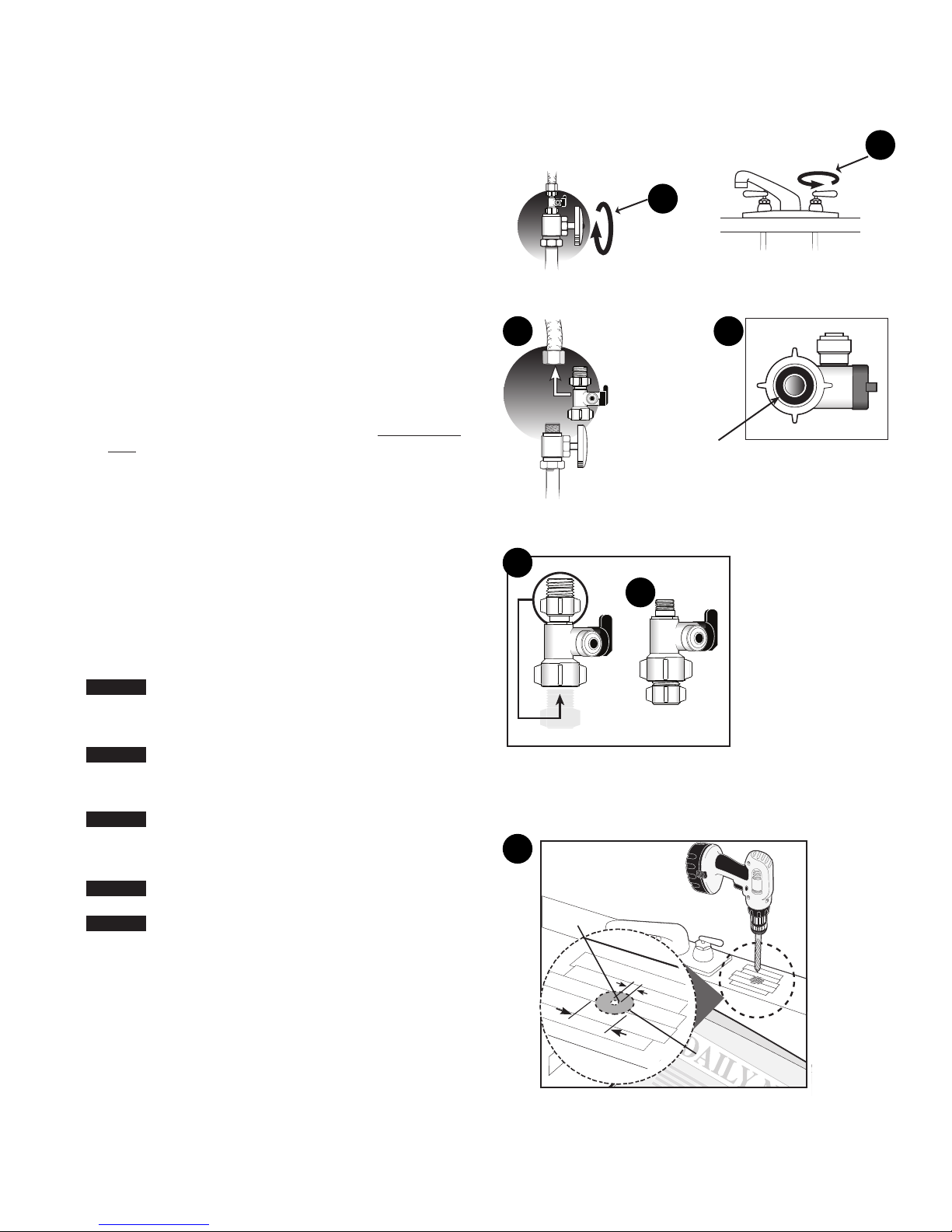
1. Installing the Water Supply Adapter
The supply adapter fits 1/2"-14 NPS supply threads or
3/8" x 3/8" compression. If local codes permit, it may be used
to connect the system to the cold water supply line. If local
codes do not permit the use of the supply adapter, alternate
connectors can be obtained from your local supplier.
A. Turn off cold water supply line. If cold water line does not
have a shut-off valve under the sink, you should install one.
B. Turn on the cold water faucet and allow all water to drain
from line.
C. Disconnect riser cold water supply valve.
D. Ensure the sealing gasket is fully seated into the feed
adapter valve female thread.
E. Install feed adapter valve onto supply valve. Hand tighten
only.
F. Connect the riser to the feed adapter valve.
NOTE: See Figures 1G-1H for configuring the feed adapter to
3/8" x 3/8" compression connections.
2. Selecting the Faucet Location
NOTE: The drinking water faucet should be positioned with
function, convenience, and appearance in mind. An
adequate flat area is required to allow faucet base to
rest securely. The faucet fits through a 3/4" hole. Most
sinks have pre-drilled 1-3⁄8" or 1-1⁄2" diameter holes
that may be used for faucet installation. If these predrilled holes cannot be used or are in an inconvenient
location, it will be necessary to drill a 3/4" hole in the
sink to accommodate the faucet.
This procedure may generate dust which can cause
severe irritation if inhaled or come in contact with
the eyes. The use of safety glasses and respirator
for this procedure is recommended.
DO NOT ATTEMPT TO DRILL THROUGH AN ALL-
PORCELAIN SINK. If you have an all-porcelain sink,
mount the faucet in pre-drilled sprayer hole or drill
through countertop next to sink.
When drilling through a countertop, make sure the
area below the drilled area is free of wiring and
piping. Make certain you have ample room to make
the proper connections to the bottom of the faucet.
Do not drill through a countertop that is more than
1" thick.
Do not attempt to drill through a tiled, marble,
granite or similar countertop. Consult a plumber
or the countertop manufacturer for advice or
assistance.
A. Line bottom of sink with newspaper to prevent metal
shavings, parts, or tools from falling down the drain.
B. Place masking tape over the area to be drilled to prevent
scratches if drill bit slips.
C. Mark hole with center punch. Use a 1/4" drill bit to drill
pilot hole.
D. Use a 3/4" drill bit and drill a hole completely through sink.
E. Smooth rough edges with a file.
1C
1G
2
1B
1A
1D
Sealing Gasket
1H
C
1
4”
D
11⁄4”
⁄
F2000-B2B, F2000-B2M Filtration Systems Instruction Manual • 3
Page 4

INSTALLATION CONTINUED
WARNING:
7” (178 mm)
16.25” (413mm)
10.75” (273 mm)
Inlet
Outlet
3. Mounting the Faucet
A. Apply 3-5 wraps of plumber tape to faucet stem.
B. Assemble faucet as shown in Figure 3.
C. Screw quick connector onto threaded end of faucet stem.
D. Place a mark 5/8" from one end of the blue tubing. Wet the
end of the 3/8" tube and push into bottom of connector. The
5/8" mark should be flush with the collar of the connector.
NOTE: To remove the tube, push on the fittings' collar and pull
the tube out.
E. Holding the faucet, feed the tubing through the hole in the
sink. Position the faucet handle at a desired location.
F. Center the faucet and slip slotted disc between the bottom
of the counter or sink and lock washer. Tighten the stem
nut with a wrench until it is tight.
G. Firmly insert spout into faucet base.
4. Mounting the System
A. Select a location under the sink, or other suitable area
where the system will be installed.
NOTE: The system carton can be used to determine the
operational footprint required for installation of the
system and replacement cartridges. (Figure 4a)
B. Mount the system vertically. Ensure mounting is level.
Place a pencil mark in the upper slots of the bracket
mounting holes. (Figure 4b). Alternate mounting option: If
mounting the system near the floor, place the pencil marks
above each of the mounting holes on the bracket to ensure
enough space resides below the cartridge and the floor for
cartridge replacement (Figure 4c). Use the 3/32" drill bit to
create pilot holes for mounting.
The system should be mounted to a firm, solid
surface that is able to support the weight of the
system.
3
4a
Faucet Stem
Chrome
Plate
Rubber
Washer
Slotted
Disk
Lock Washer
Stem Nut
Quick
Connector
3/8” Tubing
Count er Top
4b
Filter
4c
Filter
4 • F2000-B2B, F2000-B2M Filtration Systems Instruction Manual
Page 5

CAUTION
INSTALLATION CONTINUED
5. Connecting the Faucet to the System
A. Determine the length of plastic blue tubing needed to
connect to the outlet (right) side of the filter from the
faucet. Be sure to allow enough tubing to prevent kinking
and cut the tubing squarely. Use a marker to mark one end
of the tubing 5/8" from the end (Figure 5). Wet the end of
the 3/8" tube and push into the outlet (right) connection of
the system up to the mark.
Do not bend or crimp tube inserting.
B. Gently pull back on the tube to ensure it is connected
properly.
6. Connecting the Supply Adapter
A. Determine the length of plastic white tubing needed
to connect the inlet (left) side of the filter with the feed
adapter installed on the cold water supply line. Be sure to
allow enough tubing to prevent kinking and cut the tubing
squarely. Place a mark 5/8" from one end of the tubing. Wet
the end of the tubing. Insert the end of the tubing into the
3/8" fitting of the inlet supply adapter. The 5/8" mark should
be flush with the collar of the fitting located on the inlet
supply adapter (Figure 6a).
B. Mark the remaining end of the tubing. Use a marker to
mark 5/8" from the end. Wet the end of the tube. Insert the
end into the feed connection on the inlet side (left) of the
system. The tube should go in up to the mark. (Figure 6b).
7. Placing the System into Operation
A. Slowly turn on the cold water supply. Ensure that the feed
adapter valve is also open.
B. Open faucet and flush filter for 10 minutes. Discard water.
C. Check for leaks at all fittings before leaving installation. If
leaks appear, see Troubleshooting.
NOTE: A drinking water cartridge may contain carbon fines
(very fine black powder). If carbon fines appear in
the water, discard water. More flushing is required if
carbon fines are present.
NOTE: Initially, filtered water may appear cloudy. If
cloudiness in a glass of water disappears from the
bottom; fine air bubbles are present. This air within
the water will disappear within a few weeks after
installation.
5
6b
7
6a
INSTALLATION IS NOW COMPLETE.
F2000-B2B, F2000-B2M Filtration Systems Instruction Manual • 5
Page 6

FILTER CARTRIDGE REPLACEMENT
NOTE: The life of the filter cartridges depends on water
volume used and the quality of the feed water. It is
recommended that the filter cartridges be replaced
every 6-12 months, or when there is a noticeable
change in taste, odor, or flow of filtered water.
Ensure the correct cartridge set is purchased for
the system.
Model F2000-B2B and F2000-B2M use F2B2-RC2 Replacement
Cartridge set
8. Cartridge Replacement
A. Relieve pressure by turning off the water supply to the
system and opening a faucet until water flow stops. Place a
bucket or towel under the system to catch any water drips
(Figure 8a).
B. Remove the cover and lift the locking bar upward until the
filter cartridge disengages from the filter head assembly
(Figure 8b).
C. Pull the cartridge away from the filter head assembly
(Figure 8c).
D. Ensure the locking bar is fully in the up position (Figure 8c).
E. Align the posts on the filter cartridge with the ports in the
filter head assembly. Slide the cartridge filter towards into
the filter head assembly engaging with the locking bar
causing it to drop forward and down. (Figure 8d).
F. Pull down the locking bar until it snaps into place
(Figure 8e)
G. Install cover.
NOTE: See Placing the System into Operation section for
remaining steps.
8a
8b
8c
TROUBLESHOOTING
Leaks between filter head assembly and filter
cartridge
1. Relieve pressure by turning off the water supply to the
system and opening faucet until water flow stops. Place a
bucket or towel under the system to catch any water drips.
2. Remove cartridge and inspect O-rings to make sure they
are seated and clean.
3. Install filter cartridge. Place system into operation and
check for leaks. If leaks persist, turn off the water supply
and contact Technical Support at 1-800-279-9404.
Leaks from tubing fittings
1. Relieve pressure by turning off the water supply to the
system and opening faucet until water flow stops. Place a
bucket or towel under the system to catch any water drips.
2. Depress collet on system or inlet supply adapter tubing
fittings and pull tubing from fitting. Inspect surface of
tubing for scratches or debris. Clean or cut back tubing to
access clean surface.
3. Wet the end of the inlet tubing and press into the inlet
fitting of the system. Ensure the tubing is fully pushed past
the fitting O-rings. Place system into operation and check
for leaks. If leaks persist, turn off the water supply and
contact Technical Support at 1-800-279-9404.
8d
8e
6 • F2000-B2B, F2000-B2M Filtration Systems Instruction Manual
Page 7

CARTRIDGE TIMER PROCEDURE
Metal
Blinks red 1x after 11 months
Blinks red 3x after 12 months
FILTER CARTRIDGE TIMER
(MONITORED SYSTEMS ONLY)
The filter cartridge timer can be installed to the systems
decorative cover by peeling away the adhesive backing on the
metal plate included with the cartridge timer. The timer can
also be attached to a metal magnetic surface using the magnet
that is factory installed on cartridge timer.
INSTALLATION AND ACTIVATION
Once the installation location has been selected, activate the
timer by pulling the plastic tab out from the side of the timer.
Press and release the key to verify the battery is operational.
The light will blink green three times. (Figure 9a)
NOTE: The timer operates on 12 month schedule. The timer
uses a coin cell type 2023 battery.
The Filter Cartridge Timer is Operational
Operation
1. The timer will begin to blink red once every three minutes
after 11 months, and will blink red three times every three
minutes after 12 months. (Figure 9b)
NOTE: Timer status of the cartridge life can also be
viewed immediately by pressing and releasing the
key.
Reset Timer
1. To reset the timer after filter cartridge replacement, press
the key and hold for 5 seconds. The timer is now reset to 12
months. (Figure 9c)
Battery Replacement
1. Replace the battery every 12 months. To replace the battery,
locate the slot on the side of the timer body and carefully
remove the front of the timer. The battery is now accessible.
(Figure 9d)
2. Slide the new battery under the battery retention bracket
with the positive + side of the battery facing up towards the
battery retention bracket. Align the tab on the timer back
to the slot on the timer front and press and snap both timer
halves together. Battery replacement will not reset the 12
month timer. If reset is required, press and hold key for 5
seconds.
9a
9b
9c
9d
Magnet
Press and hold for 5 seconds
Blinks
Greeen 3x
Key
F2000-B2B, F2000-B2M Filtration Systems Instruction Manual • 7
Page 8

REPLACEMENT PARTS
ITEM
NUMBER
1 655126-96 Cartridge Set, F2B2-RC2 1
2
3 4003596 Installation Kit 2 & 3 Stage 1
4 244960* Faucet 1
5 4003530 Cover, 2 Stage 1
6 4003641 Cartridge Timer 1
*Image may be different than actual faucet
PART
NUMBER
4004603 Filter Head, Model F2000-B2B 1
4004605 Filter Head, Model F2000-B2M 1
DESCRIPTION
5
5
QUANTITY
REQUIRED
4
4
6
6
2
2
3
3
1
1
For replacement parts, contact your nearest Pentair distributor or call
800.279.9404
8 • F2000-B2B, F2000-B2M Filtration Systems Instruction Manual
Page 9

PERFORMANCE DATA
Important Notice: Read performance data and compare the
capabilities of the system with your actual water treatment
requirements. It is recommended that the supply water be tested,
before installing a water treatment system, to determine your water
treatment needs.
Test Conditions
Flow Rate
F2000-B2B = 0.60 gpm (2.27 L/min)
F2000-B2M = 0.60 gpm (2.27 L/min)
Filter Capacity
F2000-B2B = 675 gallons (2555 L)
F2000-B2M = 675 gallons (2555 L)
Inlet Pressure = 60 psi (4.1 bar)
Temperature = 68°F +/- 5°F (20°C+/- 2.5°F)
Testing was performed under standard laboratory conditions, actual
performance may vary.
Operating Requirements for F2000-B2B and F2000-B2M Systems:
Pressure = 40-100 psi (2.75-6.89 bar)
Temperature = 40-100°F (4.4–37.8°C)
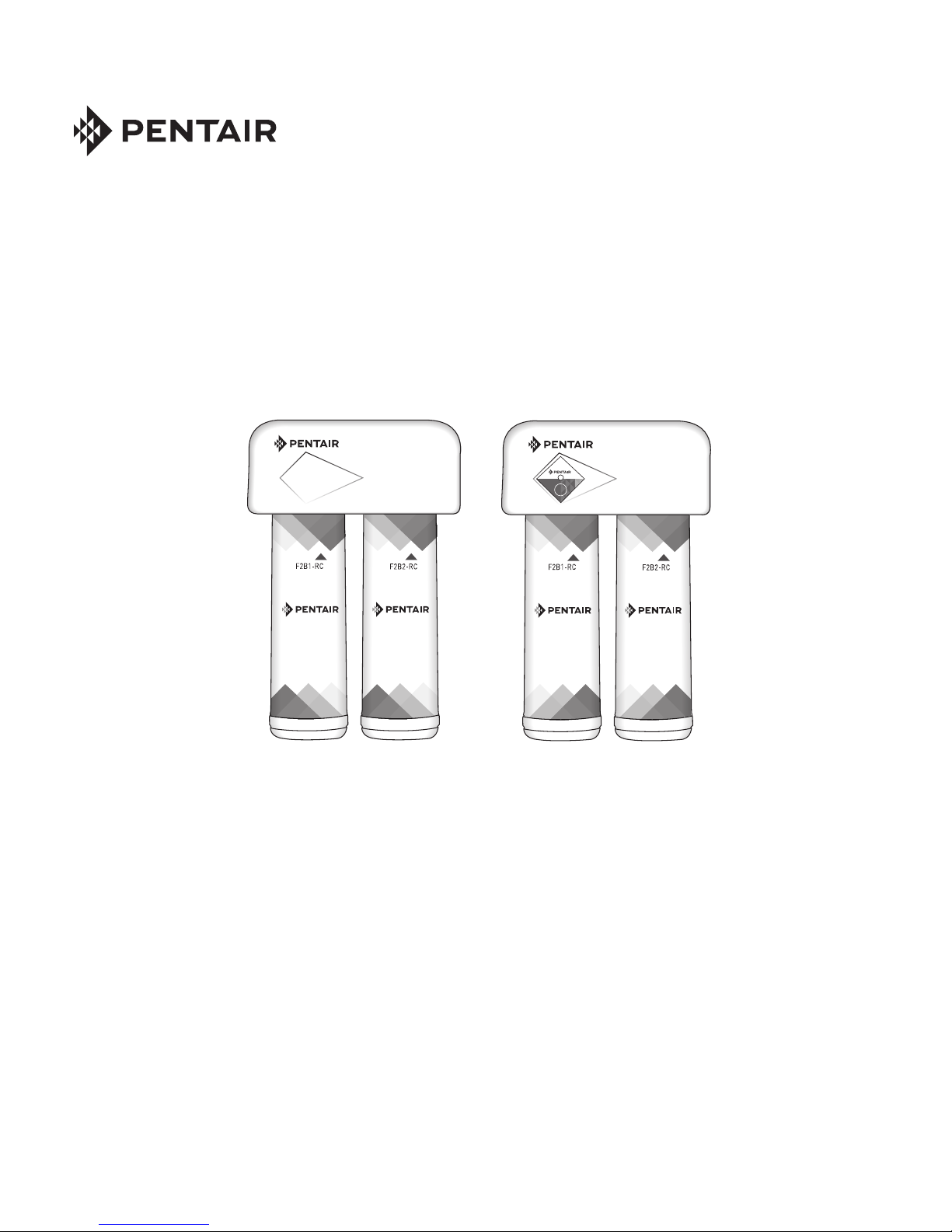
CARTRIDGE SEQUENCE
F2000-B2B F2000-B2M
F2000B2B, F2000B2M SYSTEMS
INSTALLED WITH F2B2RC2 FILTER
CARTRIDGE SET
This system has been tested according to NSF/ANSI 42 and 53 for
reduction of the substances listed below. The concentration of the
indicated substances in water entering the system was reduced to
a concentration less than or equal to the permissible limit for water
exiting the system, as specied in NSF/ANSI 42 and 53.
Conforms to NSF/ANSI 53 for VOC reduction. See performance data
sheet for individual contaminant and reduction performance.
Model F2000-B2B, F2000-B2M Systems
Max. Permissible
Product Water
Concentration
Reduction
Requirements
Minimum
Reduction
>85% 97.9%
Average
Reduction
6.5)
8.5)
(VOC
Influent Challenge
Concentration
2.0 mg/L±10% ≥50% 95.9%
at least 10,000
particulates/mL
0.15 mg/L ± 10% 0.010 mg/L 99.3% 99.9%
0.15 mg/L ± 10% 0.010 mg/L 99.3% 99.6%
0.300mg/L ± 10% 96.5% 98.8%
Substance
Standard 42
Chlorine
Taste & Odor
Particulates
(0.5-<1uM)
Class 1*
Standard 53
Cysts ** Minimum 50,000/L 99.95% 99.97% 99.99%
Atrazine 0.009 mg/L ± 10% 0.003 mg/L 90.5% 93.7%
Lead (pH
Lead (pH
Lindane 0.002 mg/L ± 10% 0.0002 mg/L 94.8% 97.4%
Chloroform
surrogate
chemical)
Flow Rate = 0.6 gpm (2.2 L/min); Capacity = 675 gallons (2555 L) or 12
months
Testing was performed under standard laboratory conditions, actual
performance may vary.
* Reduces particles as small as 0.5-1 micron in size by mechanical
means
** NSF/ANSI Standard 53 certified to reduce cysts such as
Cryptosporidium and Giardia by mechanical means.
The Model F2000-B2B and F2000-B2M are Tested and Certified by
NSF International aganist NSF/ANSI Standard 42 and 53 for the
reduction of substances specified on the Performance Data Sheet.
EPA Est. 082989-CHN-001
F2000-B2B, F2000-B2M Filtration Systems Instruction Manual • 9
Page 10

10 • F2000-B2B, F2000-B2M Filtration Systems Instruction Manual
Page 11

Page 12

For Pentair Product Warranties visit:
Pentair para las garantías de los productos visite:
Pour Pentair garanties produit visitez le site :
waterpurification.pentair.com
}
WATER QUALITY SYSTEMS
5730 NORTH GLEN PARK ROAD, MILWAUKEE, WI 53209
P: 262.238.4400 | WATERPURIFICATION.PENTAIR.COM | CUSTOMER CARE: 800.279.9404 | tech-supportpentair.com
§
For a detailed list of where Pentair trademarks are registered, please visit waterpurification.pentair.com/brands.
Pentair trademarks and logos are owned by Pentair plc or its affiliates. Third party registered and unregistered
trademarks and logos are the property of their respective owners.
4003610 REV B SE16 © 2016 Pentair Residential Filtration, LLC All Rights Reserved.
 Loading...