

Pentair EVOLIO-560 15, EVOLIO-560 8, EVOLIO-560 20, EVOLIO-560 30, EVOLIO-580 8 Operation Manual
...Page 1
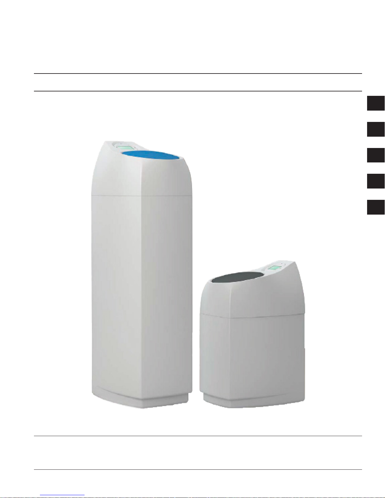
EVOLIO-560
Water Softener System
Operations manual
EN
IT
FR
DE
ES
EVOLIO-560 8 - EVOLIO-560 15 - EVOLIO-560 20 - EVOLIO-560 30
MODELS:
Page 2

EN
TABLE OF CONTENTS
INTRODUCTION ....................................................................1
SOFTENER SPECIFICATIONS .............................................2
GENERAL PRECAUTIONS ...................................................2
PROPER ORDER TO INSTALL WATER TREATING
EQUIPMENT ..........................................................................2
PRE-INSTALLATION CHECKLIST ......................................... 3
INSTALLATION ...................................................................... 3
PIPING DETAILS ....................................................................4
DRAIN REQUIREMENTS ......................................................4
SYSTEM START-UP .............................................................. 5
DISINFECTION OF WATER SOFTENERS ............................6
ADDING SALT ........................................................................6
MAINTENANCE AND REPAIR ...............................................6
TROUBLESHOOTING ...........................................................7
INTRODUCTION
Your new softener will provide years of trouble free operation
and lengthen the life of your water using appliances, such as
your washer, hot water heater, and dishwasher.
Tools Required for instalation
• Pipe wrenches
• Screw driver
• Safety glasses
• Measuring tape
• Level
• File
• Utility knife or tube
cutter
Materials Required for installation
• Pipe
• Teon® tape
• Grounding straps
(optional)
• Overow and valve drain
pipe 1/2”
• Valves
NOTE: Not all tools may be necessary for installation. Read
installation procedures before starting to determine if
additional tools are necessary
Materials Included
• Inox By-pass
EVOLIO-560
Demand Water Softener
Installation and Operating Instructions
Sys-EV-560-Man August2016 REV A • 1
Page 3

Sys-EV-560-Man August2016 REV A • 32 • Sys-EV-560-Man August2016 REV A
ENEN
EVOLIO-560 SOFTENER SPECIFICATIONS
Characteriscs
EVOLIO-560 8 EVOLIO-560 15 EVOLIO-560 20 EVOLIO-560 30
Resin liters (L) 8 15 20 30
Nominal ow
rate (m³/h)*
@10°f
0.42 0.6 0.8 1.2
Peak ow rate
(m³/h)* @10°f
0.83 1.56 2.08 3.12
Exchange
capacity (°f/m³)
40 75 100 150
Salt
consumpon
per regen. (kg)
0.96 1.8 2.4 3.6
Approx. water
consumpon
per regen (L)**
47 83 189 279
Salt storage (kg) 25 50 50 50
Width (cm) 31 31 31 31
Depth (cm) 42.5 42.5 42.5 42.5
Height (cm) 76 120 120 120
Approx. ship
weight (kg)
12 20 30 35
Note: All calculations are based on a salt dosage setting at 120g/l of resin. The softener
installation takes into account a pre-lter made of a 10” lter housing (Pentair ref.
150543) and a 10” 100micron Wound cartridge (Pentair ref. WWP100P10).
* Indicative data. Maximum ow rate to produce in order to respect the required service
velocity for an optimal ion exchange upon resin manufacturers recommendation,
regardless of the inlet pressure.
** Values may vary upon local condition and programming. All consumptions are given
for an inlet pressure of 3.44 bar (50 psi).
GENERAL PRECAUTIONS
Before you begin installation, read the entire manual. Gather
all materials and tools needed. Improper installation voids
warranty.
WARNING
Do not use with water that is microbiologically
unsafe or of unknown quality without adequate
disinfection before or after the softener.
WARNING
SODIUM INFORMATION: Water softeners using
sodium chloride for regeneration will add sodium
to the water. Persons who are on sodiumrestricted diets should consider the added
sodium as part of their overall sodium intake.
NOTE: Sodium Chloride or Potassium Chloride are
recommended for regeneration.
NOTE: The efciency of this softener shall be valid only at the
stated salt dosage calculation is made on 120g.
RECOMMENDATION: We recommend that a qualied plumber
be contracted to make all difcult piping installations.
CAUTION:
Softener must be protected against freezing, which
can cause cracking of the softener and water
leakage.
CAUTION:
Do not treat water over 43°C because hot water
will damage the softener and void warranty.
CAUTION:
Locate the softener within 500 cm of drain.
Drain must be capable of handling a maximum
backwash ow rate of 19 liters of water per minute.
PRE-INSTALLATION CHECKLIST
Installation by a licensed plumber is recommended.
1. Valves, grounding straps, wire, clamps and wall pipe, are
not supplied with the water softener.
NOTE: Ball or globe valves are recommended.
2. Electrical Requirements: AC 220V, 50 or 60HZ current
supply is required.
CAUTION:
Make certain the electrical supply cannot be turned
off accidentally.
3. Location of Softener and Drain: We recommend that the
softener be installed on a sound plumbing system within
500 cm from the drain.
NOTE: Outside faucet should be bypassed and left on
hard water.
4. Bypass Valves: Bypass valves allow you to turn off the
water to your unit but not the water service to your home.
Figure 2
5. Pre-Filtration: To prevent your softener from incoming
sediment and iron particles we recommend the installation
of a pre-lter on the water line going to the unit
INSTALLATION
RECOMMENDATION: We recommend that a qualied plumber
be contracted to make all difcult piping installations.
1. SHUT OFF FUEL SUPPLY TO WATER HEATER. See
manufacturer’s instructions.
2. Shut off all water at main supply valve.
3. Open faucet nearest pump or water meter to relieve
pressure and drain system.
CAUTION:
The water lter system should be installed
with the inlet, outlet and drain connections
made in accordance with the manufacturer’s
recommendations and to meet applicable
plumbing codes.
4. Set the water lter in place.Place in a rm concrete oor or
slab base. Be sure unit is reasonably level.
NOTE: Do not shim the tank directly for leveling. If
necessary to shim, fabricate a platform base to
set the tank on and then shim under the platform
base.
5. Shut off the water to the home. Open the highest faucet
in the plumbing system and then the lowest (you cannot
work on pipes with water in them). Make necessary piping
changes for connection of the lter to the plumbing of the
home (see Figure 5).EVOLIO-560 softeners are suplied
with 1”BSP connection
6. It is highly recommended that the bypass valve accessory
be installed
Make certain the untreated water piping connects to
the control valve on the right and the softened water is
connected on the left (Figure 4).
Figure 4
7. Connect the inlet and outlet piping. The valve connection
threads are 1” BSP. Be sure you have the incoming water
connected to the right side (Figure 4).
NOTE: Do not use pipe joint compound or plumber’s
putty on the backplate threads. Use only Teon®
Tape.
NOTE: Do not over-tighten tting to backplate.
8. Make certain proper piping alignment is maintained. Do
not apply heat to any tting connected to the conditioner or
damage to the valve may occur.
9. Move conditioner into position and level. Check all
connections for tightness.
CAUTION:
To prevent water leaks, connections to softener
must be straight when the tank is leveled
CAUTION:
Review Drain Requirements section before
connecting drainlines.
10. Carefully attach valve drain line to drain on the back of the
valve.
CAUTION:
Do not raise drain line over 2m from oor
Out In
Yoke
CAUTION:
Maximum allowable inlet water pressure is
8 Bars if daytime pressure is around 8 Bars,
nighttime pressure may exceed the maximum.
Use a pressure-reducing valve if necessary. Use a
pressure-reducing valve if necessary.
NOTE: Handle softener with care. Do not turn upside down,
drop, or set on sharp objects.
NOTE: The valve requires a minimum inlet pressure of 2 Bar
at 1.2 m3/h.
NOTE: If you are on a private well system, check minimum
water pressure with an accurate gauge. (Gauges on
older water systems are often inaccurate). Pressure
that is less than 2 Bar may cause low ow rate and
inadequate regeneration, but depending by the
pressure droop of the system.
CAUTION:
When connecting your unit, take note that the
inlet, outlet, and drain connections are made in
accordance with state and local plumbing codes.
CAUTION:
Do not over-tighten pipe to piping boss.
CAUTION:
Due to some homes using piping as a source of
electrical grounding, a grounding strap must be
installed where required.
CAUTION:
Do not heat piping if it is in contact with the control
valve.
NOTE: Do not put excessive force on the inlet/outlet drain
connections of the control valve.
NOTE: Do not use pipe joint compound or plumber’s putty
when threading pipe into the piping boss. Use only
Teon® Tape.
WARNING
Do not use any chemical substance (out off
suggested in Pg. 6) to clean resin or softener
component with out the approval of the producer
Electrical Precautions
WARNING
The unit must be plugged into an outlet.
WARNING
Do not use any extension cords.
WARNING
Locate cord where it cannot be accidentally
unplugged or cause any bodily harm.
WARNING
Electrical components are not waterproof.
CAUTION:
Make sure power source matches the rating on
the unit.
CAUTION:
Make certain the electrical supply cannot be
turned off accidentally.
NOTE: The outlet you select must not be controlled by a wall
switch.
Page 4

Sys-EV-560-Man August2016 REV A • 54 • Sys-EV-560-Man August2016 REV A
ENEN
PIPING DETAILS
Soft Water
VALVE DRAIN
LINE
1/2” Diameter
Minimum Size
OVERFLOW CABINET LINE
1/2” Diameter Minimum size
Sanitary drain, oor drain, or laundry
tubs are acceptable. Do not make a
direct connection to the drain. An air
gap must be present.
POWER
SUPPLY
CABINET
ASSEMBLY
INSTALLATION continued
11. Install salt storage tank overow line to salt tank elbow and
then run overlfow drain line to drain. DO NOT CONNECT
VALVE DRAIN LINE AND OVERFLOW DRAIN LINES
TOGETHER BY TEEING.
12. Pressure Test the Installation: The plumbing installation can
now be checked for possible leaks. Open the main water
supply valve and hot and cold water faucets. When all air
is purged from system, close faucets. Check system for
leaks over the next hour. Any leaks should be corrected
immediately.
CAUTION:
Do not reheat ttings with conditioner connected
to plumbing.
13. Plug in transformer.
14. Drain Water Heater: You can now drain the hard water
from the water heater. Let it drain until the water is
cold, then shut off the drain and RELIGHT PILOT. (See
manufacturer’s instructions).
15. Make sure that the Bypass is left in the “IN SERV” position
after installation.
16. Proceed with System Startup.
DRAIN REQUIREMENTS
If at all possible, locate the softener for optimum drain line
conditions as follows:
WARNING
To prevent electrical shock, do not place
electrical equipment or electrical cords over or
near the drain.
CAUTION:
When running the drain line to a oor drain the
area around the drain may become wet during
the regeneration process. Keep oor drain area
clean at all times to prevent any damage.
NOTE: Some states and/or counties have restrictions when
connecting the drain line to your septic system. Check
with your local authorities rst.
• Drain line should be as short as possible.
• If available, a oor drain or sump drain is most desirable.
• An elevated drain installation requires precautions as
detailed under Special Drain Line Situations below.
Typical Drain Hookups (Figure 6)
• Floor drain in basement or utility room. (Holes in drain
cover MUST be kept open.)
• Sump pit. (Sump must NOT discharge to surface watering
of lawn, shrubs, trees, etc.)
• Dry well (if legal).
• Laundry tub or clothes washer drain.
• Sanitary sewer line with sink type trap.
DRAIN REQUIREMENTS continued
Drain Adapter (Figure 7)
A drain adapter should be use to accommodate 1/2” tubing
drain line material.
On tube or hose drain line, use a hose clamp to secure drain
line to barbed tting. Also, select a rm hose that will not
soften and collapse or kink at high temperature, at suspension
points or at sharp bends. Plumbing codes do not permit a
direct connection into any sanitary or storm drain. An air gap
of at least 5cm is usually required so sewer backup will not
contaminate the system. Clamp the drain line securely to a rigid
surface to prevent it from moving during regeneration. Entire
drain system must be able to handle maximum regeneration
ow of 19 l/min. Drain should not be elevated more than
1.5 m a bove the control valve. If conditions mandate that the
drain must be higher, see discussion of special drain situations
below.
Figure 7
Special Drain Line Situations
On some installations it may be necessary to have the drain
line rise more than 1.5 m above the control valve. Explained
below are special modications for improving performance
under these adverse conditions.
Figure 8
In cases where drain line empties into an “overhead” sewer
line, a “sink” type trap must be used. Do not connect or seal
drain line to trap. Secure drain line to provide an air gap or use
an air gap device.
Figure 8
SYSTEM START-UP
Setting the Timer - Typical Residential Application To program,
set the time, set the hardness and the meter automatically
monitors system needs and regenerates only when necessary.
NOTE: During shipping the cable from the back of the timer
to the meter assembly may have been disconnected.
If it has, insert the end of the cable into the top of the
meter assembly.
Setting the Time of Day
1. Press and hold either the Up or Down buttons until the
programming icon replaces the service icon and the
parameter display reads DO.
2. Adjust the displayed time with the Up and Down buttons.
3. When the desired time is set, press the Extra Cycle button
to resume normal operation. The unit will also return to
normal operation after 5 seconds if no buttons are pressed.
User Programming Mode Steps
1. Press the Up and Down buttons for ve seconds while in
service, and the time of day is NOT set to 12:01 PM.
2. Use this display to adjust the Day Override. This option
setting is identied by “DO” in the upper left hand corner of
the screen.
3. Press the Extra Cycle button. Use this display to adjust the
Regeneration Time. This option setting is identied by “RT”
in the upper left hand corner of the screen.
4. Press the Extra Cycle button. Use this display to adjust the
Feed Water Hardness (°tH).This option setting is identied
by “H” in the upper left hand corner of the screen. Use
the hardness Kit included in the softener to set up this
parameter
Range: 1-199 (°tH) hardness
5. Press the Extra Cycle button. Use this display to adjust the
Fixed Reserve Capacity. This option setting is identied by
“RC” or “SF” in the upper left-hand Corner of the screen.
6. Press the Extra Cycle button. Use this display to set the
Current Day of the Week. This option setting is identied by
“CD” in the upper left hand corner of the screen.
7. Press the Extra Cycle button to end User Programming
Mode.
Figure 5
Valve Drain Line
Overow Drain Line
Sanitary Drain, Floor
Drain, or Laundry Tubs
are acceptable. Do not
make a direct connection
to the drain. An air gap
must be present.
Overow Drain Line 1/2”
diameter minimum size
(gravity ow)
Floor Drain
Floor Drain
Laundry Tubs
Softener
Figure 6
INCORRECT
Construct air gap as shown or purchase air
gap device as used with clothes washers.
CORRECT
5cm AIR GAP
Valve Drain Line to
Overhead Sewer
Sewer Line
Valve Drain Line
Funnel Drain
or Air Gap
Device
Trap
Page 5

Sys-EV-560-Man August2016 REV A • 76 • Sys-EV-560-Man August2016 REV A
ENEN
TROUBLESHOOTING
Problem Cause Correction
Softener fails to regenerate. Electrical service to unit has been
interrupted.
Assure permanent electrical service (check fuse,
plug, pull chain, or switch).
Timer is defective. Replace timer.
Power failure. Reset time of day.
Meter not counting liters. Check to see if cable is inserted into meter
assembly.
Softener delivers hard water. By-pass valve is open. Close by-pass valve.
No salt is in brine tank. Add salt to brine tank and maintain salt level
above water level.
Injector screen plugged. Clean injector screen.
Insufcient water owing into brine tank. Check brine tank ll time and clean brine line ow
control if plugged.
Hot water tank hardness. Repeated ushings of the hot water tank is
required.
Leak at distributor tube. Make sure distributor tube is not cracked. Check
O-ring and tube pilot.
Internal valve leak. Replace seals and spacers and/or piston.
Unit used too much salt. Improper salt setting. Check salt usage and salt setting.
Excessive water in brine tank. See “Excessive water in brine tank”.
Loss of water pressure.
Insufcient backwash ow rate
or Backwash cycle to short to
clean the resin bed
Iron buildup in line to water conditioner. Clean line to water conditioner.
Iron buildup in water conditioner. Clean control and add mineral cleaner to mineral
bed. Increase frequency of regeneration.
Inlet of control plugged due to foreign
material broken loose from pipes by recent
work done on plumbing system.
Remove piston and clean control.
Insufcient backwash ow rate or
Backwash cycle to short to clean the resin
bed.
Increase backwash cycle duration.
Check the DLFC size match with the tank size
and that it is not partially plug.
Check that drain line is not partially plugged
Loss of resin through drain
line.
Air in water system. Assure that well system has proper air eliminator
control. Check for dry well condition.
Upper and/or lower screen damaged. Check and replace damaged parts.
Iron in conditioned water. Fouled resin bed. Check backwash, brine draw, and brine tank
Increase frequency of regeneration. Increase
backwash time.
Excessive water in brine tank. Plugged drain line ow control. Clean ow control.
Incorrect brine setting. Check valve settings.
SYSTEM START-UP continued
Manually Initiating a Regeneration
1. When timer is in service, press button for 5 seconds on
the main screen.
2. The timer advances to Regeneration Cycle Step #1
(backwash), and begins programmed time count down.
3. Press the button once to advance valve to Regeneration
Cycle Step #2 (brine draw & slow rinse ).
4. Press the button once to advance valve to Regeneration
Cycle Step #3 (rapid rinse)
5. Press the button once to advance valve to Regeneration
Cycle Step #4 (brine rell full cycle).
NOTE: A queued regeneration can be initiated by pressing
the button. To clear a queued regeneration,
press the button again to cancel. If regeneration
occurs for any reason prior to the delayed
regeneration time, the manual regeneration request
shall be cleared.
Cycle Step #
EVOLIO560 8EVOLIO560 15EVOLIO560 20EVOLIO560
30
1. Backwash
2 min 3 min 3 min 4 min
2. Brine draw
& Slow rinse
20 min 38 min 76 min 114 min
3. Rapid Rinse
4 min 7 min 5 min 8 min
4. Brine
Tank Rell
3 min 5 min 7 min 11 min
DISINFECTION OF WATER SOFTENERS
NOTE: Every water softener should be disinfected after
installation; some will require periodic disinfection
during their normal life. In a few cases, disinfection with
every regeneration is recommended.
NOTE: Depending upon the conditions of use, the style of
softener, the type of ion exchanger, and the disinfectant
available, a choice can be made among the following
methods:
Sodium or Calcium Hypochlorite
5.25% Sodium Hypochlorite
IMPORTANT: Do not use any other chemical substance with
out manufacturer approval.
1. Dosage: 0.022 uid liters
2. Proceed with the normal regeneration.
ADDING SALT
NOTE: Your softener comes pre-charged and will supply you
with a day or two of soft water. Salt must be added to
the salt tank for the system to regenerate properly. This
must be done within the rst 24 - 28 hours. For the
start up use the 10Kg salt bag included
Types of Salt
Any pellet type salt is recommended due to its cleanliness
and availability. Other salts such as block, solar and rock salt
can be used; however, they may alter performance or cause
maintenance problems.
Amount of Salt
One tank units have a salt capacity of (see table pag 2).
You are not required to ll your salt tank to capacity. It is
recommended that the salt level in the salt tank always be
above the water level in the tank. This will assure that the unit
always has the correct salt dosage when it regenerates.
MAINTENANCE AND REPAIR
This unit is designed and constructed to treat the most difcult
of water. Various screens have been included in the system to
protect orices.
BEFORE doing any service work, be sure all screens are clean
and will pass water. Periodic cleaning of the screens will insure
long-term unit performance.
Lack of treated (soft) water is constant.
1. No salt in tank — Add salt to tank
2. Dirty screens — Clean screens
3. Faulted timer motor — Replace
Lack of treated (soft) water is intermittent.
Intermittent is often indicated by untreated water from the
heater (hot water) while the cold water tastes good. Intermittent
indicates excess water usage, a change in water chemistry,
or an improper frequency of regeneration. Review entire
application.
1. Low salt setting — Adjust brine value
2. Water consumption increased — Check for household leaks
3. Too infrequent regenerations — Review sizing and
reprogram timer
Brine tank overow
1. Plugged screens or injector — Clean
2. Defective Brine Valve — Clean or replace
3. Defective timer or timer motor — Replace
Service
Icon
Parameter Display
Programming Icon
Extra Cycle
Button
Down ButtonUp Button
Data Display PM Indicator
Flow Indicator
x1000 Indicator
Figure 9
Error/
Information
Icon
Page 6

CE CERTIFICATION
EVOLIO-560 softener satises all requirements of European Directive for pressure equipment 92/23/
EC following Module A(internal production control) as conformity assessment procedure; EVOLIO-560
satises all requirements of Eletromagnetic compatibility 2004/108/EC and 2006/95/EC.
Lausanne 18/08/2016
EN
8 • Sys-EV-560-Man August2016 REV A
 Loading...