

Pentair Evolio 255 Installer Manual

EVOLIO
255
INSTALLER
MANUAL
WATER PURIFICATION

Installer Manual Evolio 255 - Table of content
Table of content
1. Generalities . . . . . . . . . . . . . . . . . . . . . . . . . . . . . . . . . . . . . . . . . . 7
1.1. Scope of the documentation . . . . . . . . . . . . . . . . . . . . . . . . . . . . . . . . 7
1.2. Release management . . . . . . . . . . . . . . . . . . . . . . . . . . . . . . . . . . . . . 7
1.3. Manufacturer identifier, product . . . . . . . . . . . . . . . . . . . . . . . . . . . .7
1.4. Intended use . . . . . . . . . . . . . . . . . . . . . . . . . . . . . . . . . . . . . . . . . . . . . 7
1.5. Abbreviations used and glossary . . . . . . . . . . . . . . . . . . . . . . . . . . . . 8
1.6. Norms . . . . . . . . . . . . . . . . . . . . . . . . . . . . . . . . . . . . . . . . . . . . . . . . . . 8
1.6.1. Applicable norms . . . . . . . . . . . . . . . . . . . . . . . . . . . . . . . . . . . . . . . . . . . . 8
1.6.2. Available certificates . . . . . . . . . . . . . . . . . . . . . . . . . . . . . . . . . . . . . . . . . 8
1.7. Procedure for technical support . . . . . . . . . . . . . . . . . . . . . . . . . . . . 9
1.8. Copyright . . . . . . . . . . . . . . . . . . . . . . . . . . . . . . . . . . . . . . . . . . . . . . . 9
1.9. Limitation of liability . . . . . . . . . . . . . . . . . . . . . . . . . . . . . . . . . . . . . . 9
2. Safety . . . . . . . . . . . . . . . . . . . . . . . . . . . . . . . . . . . . . . . . . . . . . . 10
2.1. Safety pictograms definition . . . . . . . . . . . . . . . . . . . . . . . . . . . . . . . 10
2.2. Serial and safety tags location . . . . . . . . . . . . . . . . . . . . . . . . . . . . . 10
2.3. Hazards . . . . . . . . . . . . . . . . . . . . . . . . . . . . . . . . . . . . . . . . . . . . . . . . 11
2.3.1. Personnel . . . . . . . . . . . . . . . . . . . . . . . . . . . . . . . . . . . . . . . . . . . . . . . . . 11
2.3.2. Transport . . . . . . . . . . . . . . . . . . . . . . . . . . . . . . . . . . . . . . . . . . . . . . . . . . 11
2.3.3. Material . . . . . . . . . . . . . . . . . . . . . . . . . . . . . . . . . . . . . . . . . . . . . . . . . . . 11
2.4. Hygiene and sanitization . . . . . . . . . . . . . . . . . . . . . . . . . . . . . . . . . . 12
2.4.1. Sanitary issues . . . . . . . . . . . . . . . . . . . . . . . . . . . . . . . . . . . . . . . . . . . . . 12
2.4.2. Hygiene measures . . . . . . . . . . . . . . . . . . . . . . . . . . . . . . . . . . . . . . . . . . 12
3. Description . . . . . . . . . . . . . . . . . . . . . . . . . . . . . . . . . . . . . . . . . 14
3.1. Introduction to softeners . . . . . . . . . . . . . . . . . . . . . . . . . . . . . . . . . 14
3.1.1. Softening principles . . . . . . . . . . . . . . . . . . . . . . . . . . . . . . . . . . . . . . . . . 14
3.1.2. System service & regeneration cycles (7-cycles operation). . . . . . . . . 16
3.2. Technical specifications . . . . . . . . . . . . . . . . . . . . . . . . . . . . . . . . . . 18
3.2.1. General . . . . . . . . . . . . . . . . . . . . . . . . . . . . . . . . . . . . . . . . . . . . . . . . . . . 18
3.2.2. Performance flow rate characteristics. . . . . . . . . . . . . . . . . . . . . . . . . . 18
3.3. Outline drawing . . . . . . . . . . . . . . . . . . . . . . . . . . . . . . . . . . . . . . . . . 20
3.4. Description and components location . . . . . . . . . . . . . . . . . . . . . . . 21
3.5. Softener’s available options . . . . . . . . . . . . . . . . . . . . . . . . . . . . . . . 22
3.5.1. Chlorine generator and check salt led . . . . . . . . . . . . . . . . . . . . . . . . . . 22
3.5.2. Safety brine valve . . . . . . . . . . . . . . . . . . . . . . . . . . . . . . . . . . . . . . . . . . . 23
2 / 90 Ref. MKT-IM-037 / B - 17.12.2018

Installer Manual Evolio 255 - Table of content
4. Installation . . . . . . . . . . . . . . . . . . . . . . . . . . . . . . . . . . . . . . . . . .24
4.1. Warnings . . . . . . . . . . . . . . . . . . . . . . . . . . . . . . . . . . . . . . . . . . . . . . 24
4.2. Safety notices for installation . . . . . . . . . . . . . . . . . . . . . . . . . . . . . 24
4.3. Installation environment . . . . . . . . . . . . . . . . . . . . . . . . . . . . . . . . . 24
4.3.1. General. . . . . . . . . . . . . . . . . . . . . . . . . . . . . . . . . . . . . . . . . . . . . . . . . . . 24
4.3.2. Water . . . . . . . . . . . . . . . . . . . . . . . . . . . . . . . . . . . . . . . . . . . . . . . . . . . . 24
4.3.3. Electrical . . . . . . . . . . . . . . . . . . . . . . . . . . . . . . . . . . . . . . . . . . . . . . . . . 25
4.3.4. Mechanical. . . . . . . . . . . . . . . . . . . . . . . . . . . . . . . . . . . . . . . . . . . . . . . . 26
4.4. Integration constraints . . . . . . . . . . . . . . . . . . . . . . . . . . . . . . . . . . 26
4.5. Softener connection to piping . . . . . . . . . . . . . . . . . . . . . . . . . . . . . 27
4.5.1. Block diagram . . . . . . . . . . . . . . . . . . . . . . . . . . . . . . . . . . . . . . . . . . . . . 27
4.5.2. Installation layout . . . . . . . . . . . . . . . . . . . . . . . . . . . . . . . . . . . . . . . . . . 28
4.5.3. Tools and material required for installation. . . . . . . . . . . . . . . . . . . . . 28
4.5.4. Inspection/preliminary assembly . . . . . . . . . . . . . . . . . . . . . . . . . . . . . 29
4.5.5. Softener installation . . . . . . . . . . . . . . . . . . . . . . . . . . . . . . . . . . . . . . . . 29
4.5.6. Water supply line and bypass connections . . . . . . . . . . . . . . . . . . . . . . 31
4.5.7. Drain line connection . . . . . . . . . . . . . . . . . . . . . . . . . . . . . . . . . . . . . . . 33
4.5.8. Overflow line connection . . . . . . . . . . . . . . . . . . . . . . . . . . . . . . . . . . . . 35
4.5.9. Electrical connection . . . . . . . . . . . . . . . . . . . . . . . . . . . . . . . . . . . . . . . 36
5. Programming . . . . . . . . . . . . . . . . . . . . . . . . . . . . . . . . . . . . . . . .38
5.1. Display . . . . . . . . . . . . . . . . . . . . . . . . . . . . . . . . . . . . . . . . . . . . . . . . 38
5.2. Commands . . . . . . . . . . . . . . . . . . . . . . . . . . . . . . . . . . . . . . . . . . . . 40
5.3. Quick program guide . . . . . . . . . . . . . . . . . . . . . . . . . . . . . . . . . . . . 41
5.4. Basic programming . . . . . . . . . . . . . . . . . . . . . . . . . . . . . . . . . . . . . 43
5.4.1. Program system size . . . . . . . . . . . . . . . . . . . . . . . . . . . . . . . . . . . . . . . 43
5.4.2. Time setting and winter time - summer time change . . . . . . . . . . . . . 43
5.4.3. Day of week . . . . . . . . . . . . . . . . . . . . . . . . . . . . . . . . . . . . . . . . . . . . . . . 43
5.4.4. Regeneration time. . . . . . . . . . . . . . . . . . . . . . . . . . . . . . . . . . . . . . . . . . 44
5.4.5. Calendar override . . . . . . . . . . . . . . . . . . . . . . . . . . . . . . . . . . . . . . . . . . 44
5.4.6. Salt setting. . . . . . . . . . . . . . . . . . . . . . . . . . . . . . . . . . . . . . . . . . . . . . . . 44
5.4.7. Estimated capacity . . . . . . . . . . . . . . . . . . . . . . . . . . . . . . . . . . . . . . . . . 45
5.4.8. Hardness . . . . . . . . . . . . . . . . . . . . . . . . . . . . . . . . . . . . . . . . . . . . . . . . . 46
5.5. Advanced programming . . . . . . . . . . . . . . . . . . . . . . . . . . . . . . . . . . 46
5.5.1. Regeneration cycles time . . . . . . . . . . . . . . . . . . . . . . . . . . . . . . . . . . . . 47
5.5.2. History value . . . . . . . . . . . . . . . . . . . . . . . . . . . . . . . . . . . . . . . . . . . . . . 48
5.5.3. Resetting the controller . . . . . . . . . . . . . . . . . . . . . . . . . . . . . . . . . . . . . 49
Ref. MKT-IM-037 / B - 17.12.2018 3 / 90

Installer Manual Evolio 255 - Table of content
6. Commissioning . . . . . . . . . . . . . . . . . . . . . . . . . . . . . . . . . . . . . . 50
6.1. Softener commissioning . . . . . . . . . . . . . . . . . . . . . . . . . . . . . . . . . . 50
6.1.1. Water filling, draining and waterproofness inspection . . . . . . . . . . . . . 50
6.1.2. Quick cycling . . . . . . . . . . . . . . . . . . . . . . . . . . . . . . . . . . . . . . . . . . . . . . . 51
6.1.3. Startup . . . . . . . . . . . . . . . . . . . . . . . . . . . . . . . . . . . . . . . . . . . . . . . . . . . . 52
6.1.4. Additional tips . . . . . . . . . . . . . . . . . . . . . . . . . . . . . . . . . . . . . . . . . . . . . . 53
6.2. Cleaning, disinfection and sanitization . . . . . . . . . . . . . . . . . . . . . . 53
6.2.1. Cleaning of softeners . . . . . . . . . . . . . . . . . . . . . . . . . . . . . . . . . . . . . . . . 53
6.2.2. Disinfection with sodium or calcium hypochlorite. . . . . . . . . . . . . . . . . 53
6.2.3. Sanitization by electrochlorination process . . . . . . . . . . . . . . . . . . . . . . 54
7. Operation . . . . . . . . . . . . . . . . . . . . . . . . . . . . . . . . . . . . . . . . . . . 55
7.1. Display . . . . . . . . . . . . . . . . . . . . . . . . . . . . . . . . . . . . . . . . . . . . . . . . 55
7.1.1. During operation . . . . . . . . . . . . . . . . . . . . . . . . . . . . . . . . . . . . . . . . . . . . 55
7.1.2. During regeneration . . . . . . . . . . . . . . . . . . . . . . . . . . . . . . . . . . . . . . . . . 55
7.2. Manual regeneration . . . . . . . . . . . . . . . . . . . . . . . . . . . . . . . . . . . . . 56
7.2.1. Manual delayed regeneration . . . . . . . . . . . . . . . . . . . . . . . . . . . . . . . . . 56
7.2.2. Immediate regeneration. . . . . . . . . . . . . . . . . . . . . . . . . . . . . . . . . . . . . . 56
7.2.3. To advance regeneration cycles . . . . . . . . . . . . . . . . . . . . . . . . . . . . . . . 56
7.2.4. To cancel a regeneration . . . . . . . . . . . . . . . . . . . . . . . . . . . . . . . . . . . . . 56
7.2.5. Second delayed regeneration . . . . . . . . . . . . . . . . . . . . . . . . . . . . . . . . . 57
7.2.6. Second immediate regeneration . . . . . . . . . . . . . . . . . . . . . . . . . . . . . . . 57
7.3. Operation during a power failure . . . . . . . . . . . . . . . . . . . . . . . . . . .57
4 / 90 Ref. MKT-IM-037 / B - 17.12.2018

Installer Manual Evolio 255 - Table of content
8. Maintenance . . . . . . . . . . . . . . . . . . . . . . . . . . . . . . . . . . . . . . . . .58
8.1. General system inspection . . . . . . . . . . . . . . . . . . . . . . . . . . . . . . . 58
8.1.1. Water quality . . . . . . . . . . . . . . . . . . . . . . . . . . . . . . . . . . . . . . . . . . . . . . 58
8.1.2. Mechanical Checks . . . . . . . . . . . . . . . . . . . . . . . . . . . . . . . . . . . . . . . . . 58
8.1.3. Regeneration test . . . . . . . . . . . . . . . . . . . . . . . . . . . . . . . . . . . . . . . . . . 59
8.2. Recommended maintenance plan . . . . . . . . . . . . . . . . . . . . . . . . . 59
8.2.1. Maintenance instructions . . . . . . . . . . . . . . . . . . . . . . . . . . . . . . . . . . . . 60
8.3. Adding salt . . . . . . . . . . . . . . . . . . . . . . . . . . . . . . . . . . . . . . . . . . . . 61
8.4. Recommendations . . . . . . . . . . . . . . . . . . . . . . . . . . . . . . . . . . . . . . 62
8.4.1. Use original spare parts . . . . . . . . . . . . . . . . . . . . . . . . . . . . . . . . . . . . . 62
8.4.2. Use original approved lubricants. . . . . . . . . . . . . . . . . . . . . . . . . . . . . . 62
8.5. Cleaning and maintenance . . . . . . . . . . . . . . . . . . . . . . . . . . . . . . . 62
8.5.1. First steps . . . . . . . . . . . . . . . . . . . . . . . . . . . . . . . . . . . . . . . . . . . . . . . . 62
8.5.2. Covers removal (softener and valve) . . . . . . . . . . . . . . . . . . . . . . . . . . . 63
8.5.3. Brine tank and brine well cleaning . . . . . . . . . . . . . . . . . . . . . . . . . . . . 64
8.5.4. Cleaning the injector screen . . . . . . . . . . . . . . . . . . . . . . . . . . . . . . . . . 66
8.5.5. Cleaning the injector. . . . . . . . . . . . . . . . . . . . . . . . . . . . . . . . . . . . . . . . 67
8.5.6. Controller replacement . . . . . . . . . . . . . . . . . . . . . . . . . . . . . . . . . . . . . 68
8.5.7. Other wear and tear parts . . . . . . . . . . . . . . . . . . . . . . . . . . . . . . . . . . . 69
9. Troubleshooting . . . . . . . . . . . . . . . . . . . . . . . . . . . . . . . . . . . . . .78
9.1. Controller . . . . . . . . . . . . . . . . . . . . . . . . . . . . . . . . . . . . . . . . . . . . . 78
9.2. Valve . . . . . . . . . . . . . . . . . . . . . . . . . . . . . . . . . . . . . . . . . . . . . . . . . 79
9.3. System . . . . . . . . . . . . . . . . . . . . . . . . . . . . . . . . . . . . . . . . . . . . . . . . 80
Ref. MKT-IM-037 / B - 17.12.2018 5 / 90

Installer Manual Evolio 255 - Table of content
10. Spare parts . . . . . . . . . . . . . . . . . . . . . . . . . . . . . . . . . . . . . . . . . 82
10.1. Softener . . . . . . . . . . . . . . . . . . . . . . . . . . . . . . . . . . . . . . . . . . . . . . . 82
10.2. Valve . . . . . . . . . . . . . . . . . . . . . . . . . . . . . . . . . . . . . . . . . . . . . . . . . . 84
10.2.1. Valve body parts list . . . . . . . . . . . . . . . . . . . . . . . . . . . . . . . . . . . . . . . . . 84
10.2.2. Evolio 255 controller. . . . . . . . . . . . . . . . . . . . . . . . . . . . . . . . . . . . . . . . . 86
10.2.3. Meters . . . . . . . . . . . . . . . . . . . . . . . . . . . . . . . . . . . . . . . . . . . . . . . . . . . . 86
10.3. Piping . . . . . . . . . . . . . . . . . . . . . . . . . . . . . . . . . . . . . . . . . . . . . . . . . 87
10.3.1. Bypass & connections . . . . . . . . . . . . . . . . . . . . . . . . . . . . . . . . . . . . . . . 87
11. Disposal . . . . . . . . . . . . . . . . . . . . . . . . . . . . . . . . . . . . . . . . . . . . 88
6 / 90 Ref. MKT-IM-037 / B - 17.12.2018
Installer Manual Evolio 255 - Generalities
1. Generalities
1.1. Scope of the documentation
This documentation provides the necessary information for appropriate use of the product and
informs users to ensure efficient execution of the installation, operation or maintenance procedures.
The content of this document is based on the information available at the time of publication. The
original version of the document was written in English.
For safety and environmental protection reasons, the safety instructions given in this documentation
must be strictly followed.
This manual is a reference and will not include every system installation situation. The person
installing this equipment should have:
• training in the 255 valves with 700 Logix series controllers and water softener installation;
• knowledge of water conditioning and how to determine proper controller settings;
• basic plumbing skills.
This document is available in other languages on https://www.pentairaquaeurope.com/product-
finder/product-type/softeners.
1.2. Release management
Revision Date Authors Description
A 14.05.2018 BRY/FLA First edition.
B 17.12.2018 BRY/FIM Security instructions
1.3. Manufacturer identifier, product
Manufacturer: Pentair International LLC
Avenue de Sevelin 18
1004 Lausanne
Switzerland
Product: Evolio 255
1.4. Intended use
• For domestic use only;
• the water softener series Evolio 255 may only and exclusively be used for residential water
softening under specified conditions, see 4.3.2. Water, page 24;
• the water softener series Evolio 255 protects water pipes and connected water-carrying systems
from scaling, respectively from malfunctions and damage caused by scaling;
• the water softener series Evolio 255 is designed for continuous supply of water for different
family sizes depending on the chosen model.
Ref. MKT-IM-037 / B - 17.12.2018 7 / 90

Installer Manual Evolio 255 - Generalities
1.5. Abbreviations used and glossary
Refill Controller...................................... Brine Line Flow Controller
DLFC ....................................................... Drain Line Flow Controller
Regen...................................................... Regeneration
1.6. Norms
1.6.1. Applicable norms
Comply with the following guidelines:
• 2006/42/EC: Machinery Directive;
• 2014/35/UE: Low Voltage Directive;
• 2014/30/UE: Electromagnetic compatibility;
• 2011/65/EC: Restriction of use of certain hazardous substances in electrical and electronic
equipment (RoHS);
• UNI EN ISO9001 (certificate no. 95.022 SSG ICS).
Meets the following technical standards:
• IEC/EN 60335-1;
• IEC 61010-1;
• EN 55014-1;
• EN 55014-2;
• EN 61000-3-2: 2006 + A1: 2009 + A2: 2009;
• EN 61000-3-3: 2008;
• EN 61000-6-2: 2005;
• EN 61000-6-3: 2007 + A1: 2011;
• EN 61326-1.
1.6.2. Available certificates
•CE;
•DM174;
•ACS.
8 / 90 Ref. MKT-IM-037 / B - 17.12.2018
Access to all certifications:

Installer Manual Evolio 255 - Generalities
1.7. Procedure for technical support
Procedure to follow for any technical support request:
A Collect the required information for a technical assistance request.
→ Product identification (see 2.2. Serial and safety tags location, page 10 and
8.1.2. Mechanical Checks, page 58);
→ Problem description.
B Please refer to the "Troubleshooting" chapter, page 78. If the problem persists contact your
supplier.
1.8. Copyright
© 2018 Pentair International Sàrl All rights reserved.
1.9. Limitation of liability
Pentair Quality System EMEA products benefit, under specific conditions, from a manufacturer
warranty that may be invoked by Pentair’s direct customers. Users should contact the vendor of this
product for applicable conditions and in case of a potential warranty claim.
Any warranty provided by Pentair regarding the product may become invalid in case of:
• installation done by a non-water-professional;
• improper installation, improper programming, improper use, improper operation and/or
maintenance leading to any kind of product damages;
• improper or unauthorized intervention on the controller or components;
• incorrect, improper or wrong connection/assembly of systems or products with this product and
vice versa;
• use of a non-compatible lubricant, grease or chemicals of any type and not listed by the
manufacturer as compatible for the product;
• failure due to wrong configuration and/or sizing.
Pentair accepts no liability for equipment installed by the user upstream or downstream of Pentair
products, as well as for process/production processes which are installed and connected around or
even related to the installation. Disturbances, failures, direct or indirect damages that are caused by
such equipment or processes are also excluded from the warranty. Pentair shall not accept any
liability for any loss or damage of profits, revenues, use, production, or contracts, or for any indirect,
special or consequential loss or damage whatsoever. Please refer to the Pentair List Price to know
more about terms and conditions applicable to this product.
Ref. MKT-IM-037 / B - 17.12.2018 9 / 90
Installer Manual Evolio 255 - Safety
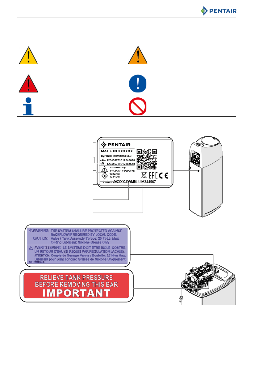
Model
Electrical rating
Part number
Serial number
Production date
Production order
2. Safety
2.1. Safety pictograms definition
CAUTION
Warns of a risk of minor injury or
major material damage to the device
or environment.
DANGER
Warns against serious personal injury
or death.
NOTE
Comment.
2.2. Serial and safety tags location
WARNING
Warns against serious personal injury
and damage to health.
MANDATORY
Standard or measure to apply.
PROHIBITION
Restriction to be observed.
10 / 90 Ref. MKT-IM-037 / B - 17.12.2018

Installer Manual Evolio 255 - Safety
NOTE
Ensure that the serial label and the safety tags on the device are completely legible and
clean. If necessary, replace them with new tags and put them in the same places.
2.3. Hazards
All the safety and protection instructions contained in this document must be observed in order to
avoid temporary or permanent injury, damage to property or environmental pollution.
At the same time, any other legal regulations, accident prevention and environmental protection
measures, as well as any recognized technical regulations relating to appropriate and risk-free
methods of working which apply in the country and place of use of the device must be adhered to.
Any non-observation of the safety and protection rules, as well as any existing legal and technical
regulations, will result in a risk of temporary or permanent injury, damage to property or
environmental pollution.
2.3.1. Personnel
Only qualified and professional personnel, based on their training, experience and instruction as well
as their knowledge of the regulations, the safety rules and operations performed, are authorized to
carry out necessary work.
2.3.2. Transport
The following points must be observed to ensure proper operation of the system:
• do not lay down or flip over the softener at any time. The media may paste to the upper
distributor thus obstructing its slots or enter the valve and may therefore compromise the
softener operation;
• pay attention not to hit the softener;
• use all the safety lifting systems to move the softener;
• do not lift the softener by the valve or bypass.
2.3.3. Material
The following points must be observed to ensure proper operation of the system and the safety of
user:
• do not remove the locking bar while system is pressurized;
• beware of high voltages present on the transformer (220-230VAC);
• do not put your fingers in the system (risk of injuries with moving parts and shock due to electric
voltage).
Ref. MKT-IM-037 / B - 17.12.2018 11 / 90
Installer Manual Evolio 255 - Safety
2.4. Hygiene and sanitization
2.4.1. Sanitary issues
Preliminary checks and storage
• Check that the brine tank and the brine well are clean and free from burr, debris or any scraps;
• check the integrity of the packaging. Check that there is no damage and no signs of contact with
liquid to make sure that no external contamination occurred;
• the packaging has a protective function and must be removed just before installation. For
transportation and storage appropriate measures should be adopted to prevent the
contamination of materials or objects themselves.
Assembly
• Assemble only with components which are in accordance with DM 174 and ACS or any local
norm/certification;
• after installation and before use, perform one or more manual regenerations in order to clean
the media bed. During such operations, do not use the water for human consumption. Perform a
disinfection of the system in the case of installations for treatment of drinking water for human
use.
NOTE
This operation must be repeated in the case of ordinary and extraordinary maintenance. It
should also be repeated whenever the system remains idle for a significant time.
NOTE
Valid only for Italy
signs and obligations arising from the DM25.
2.4.2. Hygiene measures
DANGER
Do not use with water that is micro-biologically unsafe or of unknown quality without
adequate disinfection before or after the softener.
WARNING
Water softeners using sodium chloride for regeneration will add sodium to the water.
Person who are on sodium-restricted diets should consider the added sodium as part of
their overall sodium intake.
: In case of equipment used in accordance with the DM25, apply all the
12 / 90 Ref. MKT-IM-037 / B - 17.12.2018

Installer Manual Evolio 255 - Safety
Disinfection
• The materials used for the construction of our products meet the standards for use with potable
water; the manufacturing processes are also geared to preserving these criteria. However, the
process of production, distribution, assembly and installation, may create conditions of bacterial
proliferation, which may lead to odour problems and water contamination;
• it is therefore strongly recommended to sanitize the products. See 6.2. Cleaning, disinfection and
sanitization, page 53;
• maximum cleanliness is recommended during the assembly and installation;
• for disinfection, use sodium or calcium hypochlorite and perform a manual regeneration.
Ref. MKT-IM-037 / B - 17.12.2018 13 / 90
Installer Manual Evolio 255 - Description
Hardness Resin bead Exhausted resin
bead
Soft water
Saturated
brine
Exhausted
resin bead
Regenerated
resin bead
Waste Excess
salt
3. Description
3.1. Introduction to softeners
3.1.1. Softening principles
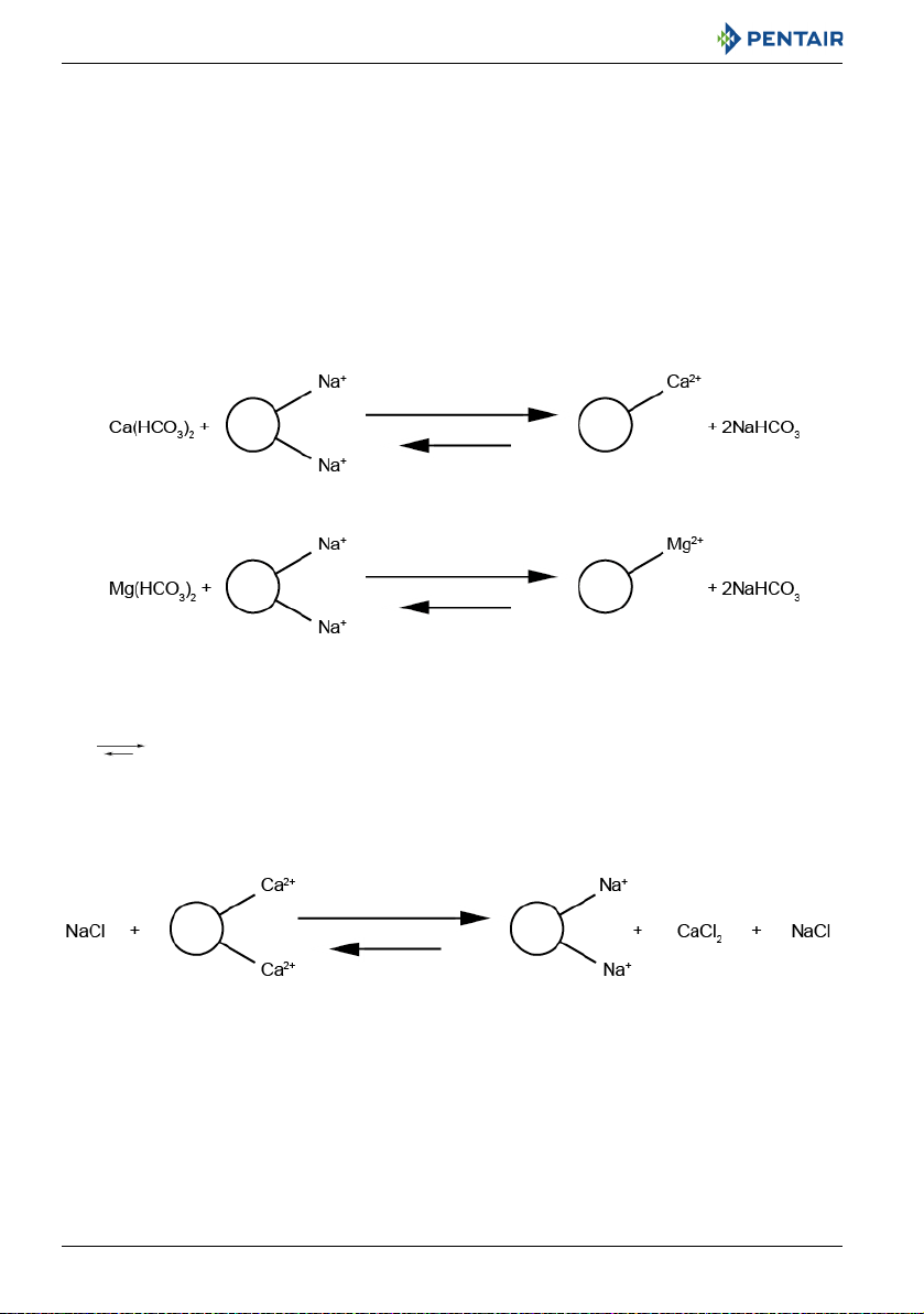
Softening is an ion exchange process where the hard ions are getting exchange by soft ions, typically
sodium or potassium. This is achieved by placing the water in contact with an ion exchange resin and
ensuring the contact time is appropriate for the flow rate to produce.
The basic chemistry of softening resins is very simple: the resin is made of small polymer beads with
chemical functionality that selectively captures the divalent ions (such as Ca
ions) and releases in exchange less tightly held monovalent ions, usually sodium (Na
frequently potassium. Here below is shown the chemical reactions mechanism for softening:
2+
and Mg2+ - hardness
+
) or less
The means that under certain conditions, the reactions can be reversed. This is due to the
equilibrium between the water composition and the amount of hardness that can be removed. This
reverse reaction is observed at different kinetics and at high monovalent ions concentration. Usually
for softening this conditions are obtained using concentrated NaCl (or KCl) solutions that are put in
contact with the resin. This is called regeneration:
14 / 90 Ref. MKT-IM-037 / B - 17.12.2018

Installer Manual Evolio 255 - Description
The service and regeneration reaction can be done over and over, so softening systems last years.
A softener consists of different components:
• a tank, filled with softening resin;
• a valve, that will direct the inlet water flow on the resin bed so that the softening or regeneration
reaction can take place;
• a timer, that will control when the regeneration phases have to be done;
• a brine tank, where saturated brine solution is prepared for the regenerations.
The present softener will simply allow the previously described reaction to happen, alternating
softening period of few days with regeneration that may last up to few hours depending on setting
done. The softener is equipped with a controller that will trigger automatically the different phases of
service and regeneration upon the programming done.
The valve configuration has been chosen to be in accordance with the volume of resin contained in the
tank. Do not intend to modify it or you may cause kinetics changes and may cause regeneration
malfunction.
In order to ensure proper softener function, make sure it always contains salt in the brine tank and
remains electrically powered. Softener installation, start up and programming must be done by
trained professional water treatment specialist. Incorrect installation or wrong programming may
cause softener malfunctions or even damage the softener and its components.
Respect programming recommendations for each softener size in order to achieve best optimized
softener performances.
Softener requires periodical cleaning/maintenance operations to ensure proper function over years.
Those are described in the present manual on chapter 8. Maintenance, page 58.
Ref. MKT-IM-037 / B - 17.12.2018 15 / 90

Installer Manual Evolio 255 - Description
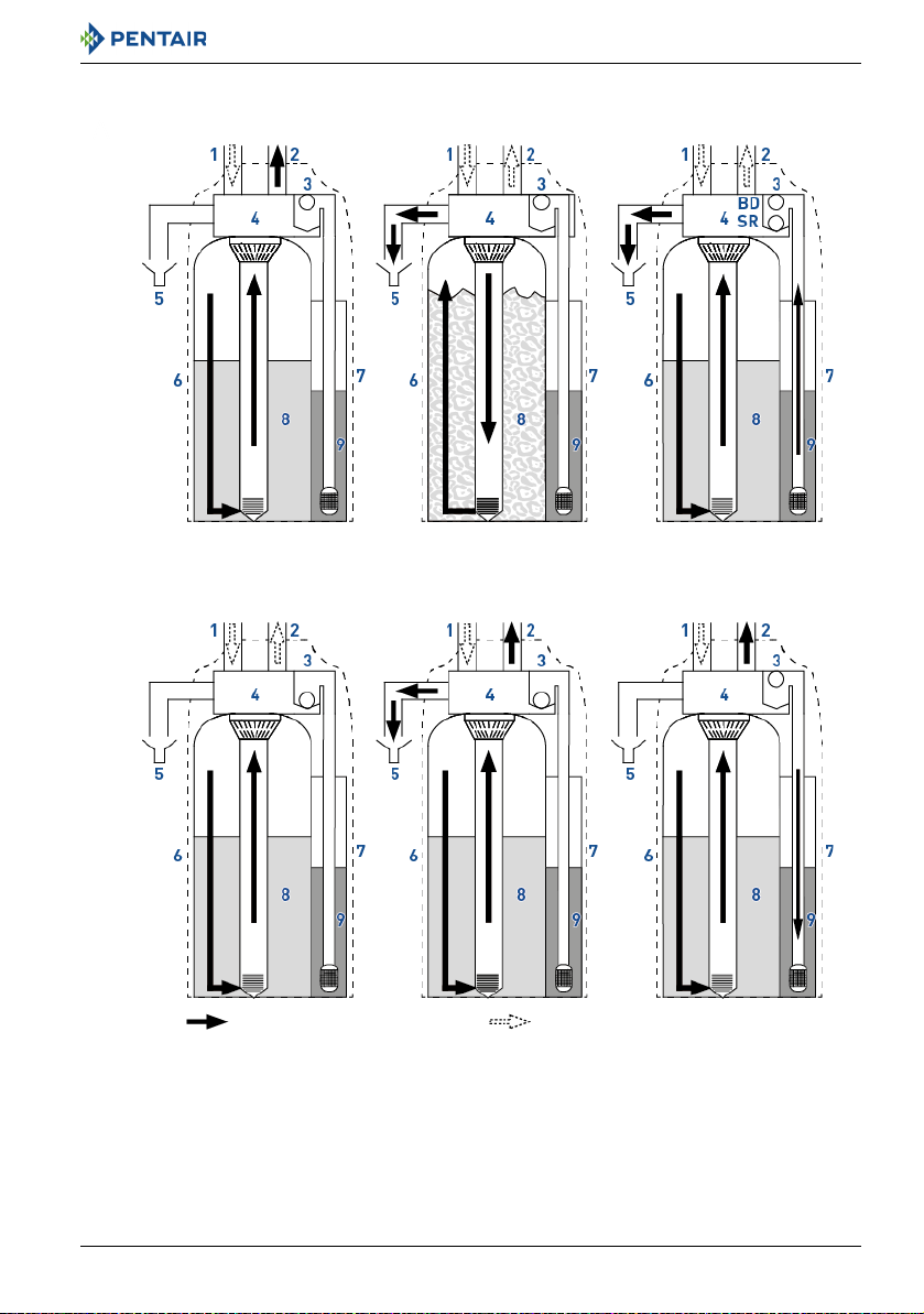
3.1.2. System service & regeneration cycles (7-cycles operation)
Service — cycle C0
Untreated water is directed down through the resin bed and up through the riser tube. The hardness
ions attach themselves to the resin and are removed from the raw water being exchanged on the resin
beads towards sodium ions. The water is conditioned as it passes through the resin bed.
Backwash — cycle C1
The flow of water is reversed by the valve and directed down the riser tube and up through the resin
bed. During the backwash cycle, the bed is expanded and debris is flushed to the drain, while the
media bed is remixed.
Brine draw & slow rinse — cycle C2-C3
The controller directs water through the brine injector and brine is drawn from the brine tank. The
brine is then directed down through the resin bed and up through the riser tube to the drain. The
hardness ions are displaced by sodium ions and are sent to the drain. When the air check valve closes
brine drawing finishes, and then the slow rinse phase starts. The resin is regenerated during the brine
draw and slow rinse cycles.
Repressurize cycle (hard water bypass flapper open) — cycle C4
This cycle allows the air and water to hydraulically balance in the valve before continuing the
regeneration.
Rapid rinse — cycle C5
The controller value directs water down through the resin bed and up through the riser tube to the
drain. Any residual brine is rinsed from the resin bed, while the media bed is re-compacted.
2nd Backwash — cycle C6
2nd Rapid rinse — cycle C7
Brine refill — cycle C8
Water is directed to the brine tank at a rate controlled by the refill controller, to create brine for the
next regeneration. During brine refill, treated water is already available at the valve outlet.
NOTE
For illustration purpose only. Always verify inlet and outlet marking on the softener.
16 / 90 Ref. MKT-IM-037 / B - 17.12.2018
Installer Manual Evolio 255 - Description
BRINE DRAW/SLOW RINSE
C2-C3
BACKWASH
C1 and C6
SERVICE
C0
BRINE REFILL
C8
RAPID RINSE
C5 and C7
REPRESSURIZE
C4
7 Brine tank
8Media bead
9Brine
4Valve
5Drain
6Media tank
1Inlet
2Outlet
3Air check
Soft water Hard water
Ref. MKT-IM-037 / B - 17.12.2018 17 / 90
Installer Manual Evolio 255 - Description
Drain
Inlet
Outlet
Overflow
3.2. Technical specifications
3.2.1. General
Softener type
Evolio....................................................... 255 10L.............255 15L.............255 20L ............ 255 30L
Design specifications/ratings
Softener cabinet ..................................... ABS
Tank body................................................ Dowex
Valve body ............................................... Glass-filled Noryl
Rubber components ............................... Compounded for cold water - NSF listed material
Valve material certification .................... WQA Gold Seal Certified to ORD 0902, NSF/ANSI 44, CE, ACS
Volume of resin....................................... 10 L...................15 L...................20 L ..................30 L
Approximative shipping weight .............. 12 kg .................20 kg.................30 kg ................ 35 kg
Salt storage ............................................ 25 kg.................50 kg................. 50 kg ................ 50 kg
Operating pressure ................................ 1.4 - 8.6 bar
Hydrostatic test pressure....................... 20 bar
Water temperature................................. 1 - 38°C
Ambient temperature............................. 2 - 50°C
®
HCRS-s resin
®
- NSF listed material
3.2.2. Performance flow rate characteristics
NOTE
Flow rates are indicative data. Maximum flow rate to produce in order to respect the
required service velocity for an optimal ion exchange upon resin manufacturers
recommendation, regardless of the inlet pressure.
18 / 90 Ref. MKT-IM-037 / B - 17.12.2018
Installer Manual Evolio 255 - Description
Nominal (residual hardness 0°f)............ 0.6 m3/h........... 0.9 m3/h............1.2 m3/h ...........1.8 m3/h
Nominal (residual hardness 5-10°f) ...... 0.7 m
Peak (residual hardness 5-10°f) ............ 1.0 m
Softening
Number of people................................... 1-2 ................... 3-4....................4-5 .................... 6-8
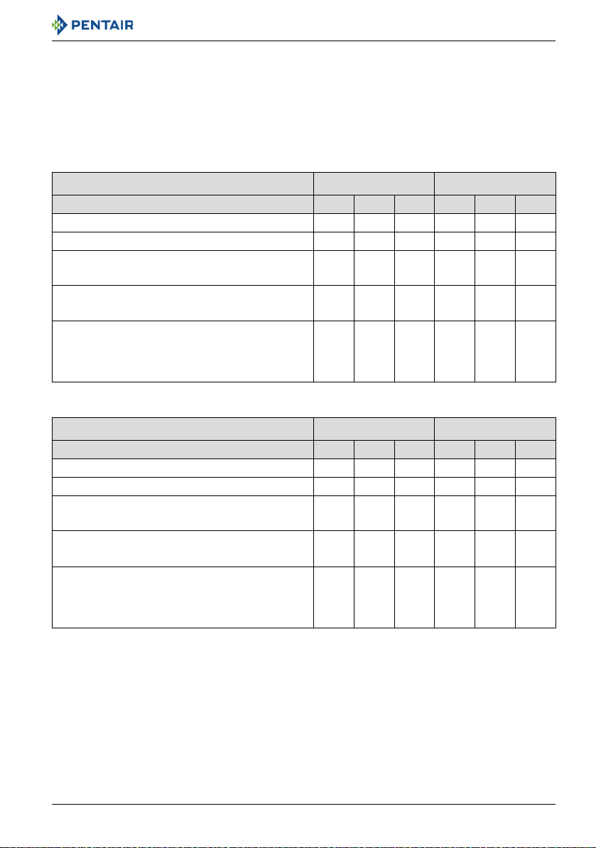
Capacity & salt consumption for the different salt dosage setting
Softener
Programmed salt setting L S H L S H
Corresponding salt dosage (g/L of resin) 45.0 91.0 180.0 46.7 133.3 226.7
Salt amount per regen (kg) 0.5 0.9 1.8 0.7 2.0 3.4
Capacity (kg as CaCO3) to program (override
preprogrammed capacity)
Capacity in m3 (for 300ppm inlet hardness and
100ppm residual hardness)
Estimated salt consumption in kg per person and
per year for 200L daily water consumption per
person and 300ppm inlet hardness, residual
100ppm
Softener
Programmed salt setting L S H L S H
Corresponding salt dosage (g/L of resin) 55.0 160.0 250.0 53.3 136.7 226.7
Salt amount per regen (kg) 1.1 3.2 5.0 1.6 4.1 6.8
Capacity (kg as CaCO3) to program (override
preprogrammed capacity)
Capacity in m3 (for 300ppm inlet hardness and
100ppm residual hardness)
Estimated salt consumption in kg per person and
per year for 200L daily water consumption per
person and 300ppm inlet hardness, residual
100ppm
3
/h........... 1.1 m3/h............1.4 m3/h ...........2.2 m3/h
3
/h........... 1.5 m3/h............2.0 m3/h ...........3.0 m3/h
Evolio 255 10L Evolio 255 15L
0.3 0.5 0.7 0.5 0.9 1.2
1.5 2.5 3.5 2.5 4.5 6.0
21.9 26.6 37.5 20.4 32.4 41.4
Evolio 255 20L Evolio 255 30L
0.7 1.4 1.6 1.0 1.9 2.3
3.5 7.0 8.0 5.0 9.5 11.5
22.9 33.4 45.6 23.4 31.5 43.2
Softener connections
Inlet/Outlet.............................................. 1" BSPT, female
Drain line
Overflow drain line
Ref. MKT-IM-037 / B - 17.12.2018 19 / 90
............................... ½"
..................... ½"
Installer Manual Evolio 255 - Description
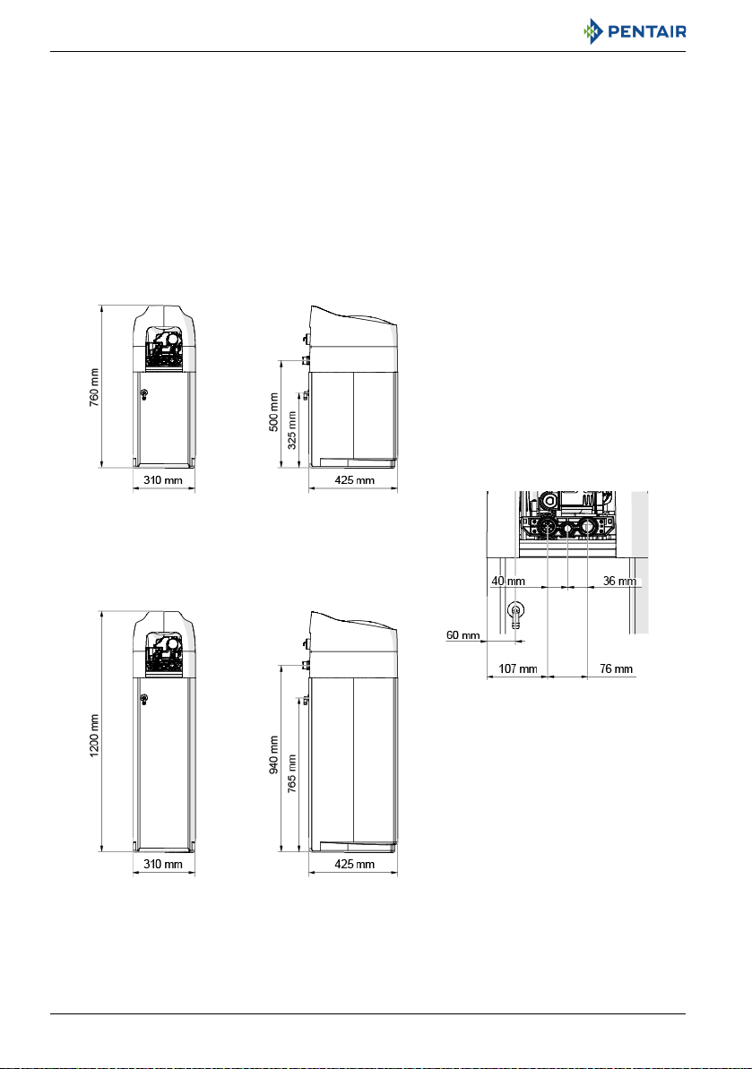
Evolio 255 10L model
Evolio 255 15, 20 and 30L models
Evolio 255 all models
Electrical
Transformer input voltage ..................... 220-230 VAC 50/60 Hz
Softener max. power consumption ........ 3 W
Protection rating..................................... IP 22
Transient overvoltages........................... within the limits of category II
Pollution Degree..................................... 3
Temporary overvoltages must be limited in duration and in frequency.
3.3. Outline drawing
20 / 90 Ref. MKT-IM-037 / B - 17.12.2018
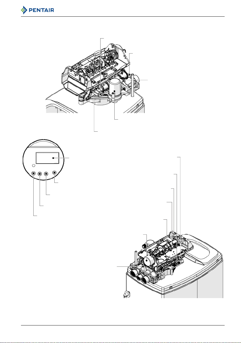
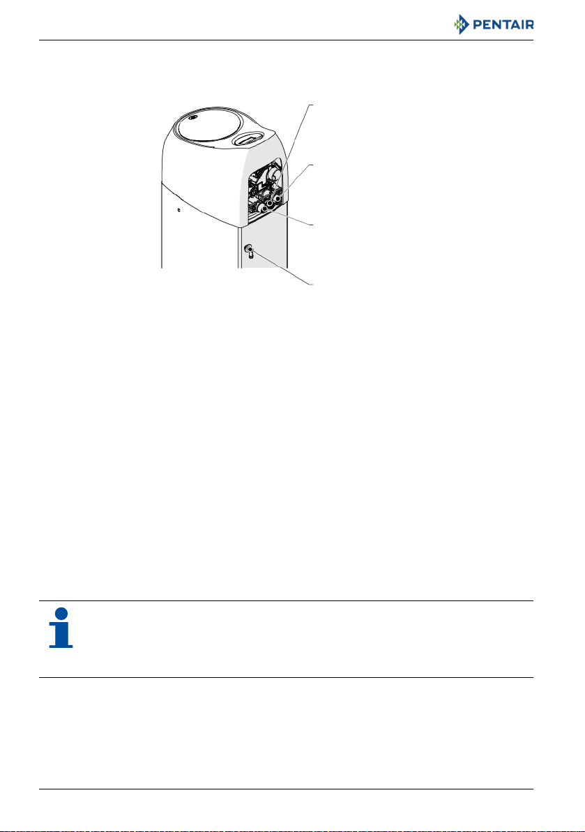
3.4. Description and components location
LCD display
Down arrow
Set
Up arrow
Regeneration
BLFC/Refill controller
Injector and cap
Air check
Brine tank tube connection
Turbine manifold
Optical sensor
Injector screen
Locking bar
Valve discs/flappers
Camshaft
Motor
Turbine cable connection
Installer Manual Evolio 255 - Description
Ref. MKT-IM-037 / B - 17.12.2018 21 / 90
Installer Manual Evolio 255 - Description
3.5. Softener’s available options
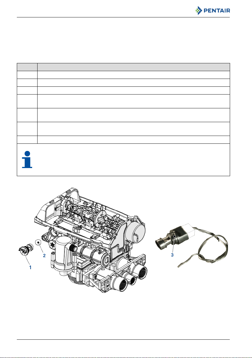
3.5.1. Chlorine generator and check salt led
The Evolio 255 controller has the capability to produce a low level of chlorine to chlorinate the resin
bed during regeneration. A check salt light will indicate when the user needs to add salt to the brine
tank. Potassium chloride or sodium chloride may be used.
No. Operation
A Unplug the wall-mounted transformer.
B Shut off water supply or put bypass valve(s) into bypass position.
C Relieve system pressure before performing any operations.
Remove the softener’s and valve’s covers, see 8.5.2. Covers removal (softener and valve),
D
page 63.
Remove the existing refill controller (1) with the ball (2) from the valve and replace it with
E
the one (3) provided in the kit (P/N 1244336).
Connect the end of the cable (P/N 1206065) to the refill controller previously installed.
F
Connect firmly to ensure a good contact.
G Reverse above procedure steps to rebuild.
CAUTION
No programming is necessary for the chlorine generator to work properly on the
controller. The system will be automatically functional after the chlorine generation
senses brine for the first time. There is a check salt light on the front of the controller that
will switch ON when there is no brine present during the brine draw.
22 / 90 Ref. MKT-IM-037 / B - 17.12.2018

Installer Manual Evolio 255 - Description
1037194
1036840
3.5.2. Safety brine valve
To avoid overflow and to get a better softener operation, a safety brine valve can be installed.
No. Operation
A Remove the softener covers, see 8.5.2. Covers removal (softener and valve), page 63.
B Remove the brine well cover.
Remove the brine tube (P/N 3028267) and replace it with the brine valve (P/N 1036840)
C
and its brine tube (P/N 1037194)
D Put the brine well cover back in place.
E Remount the softener covers, see 8.5.2. Covers removal (softener and valve), page 63.
Ref. MKT-IM-037 / B - 17.12.2018 23 / 90
Installer Manual Evolio 255 - Installation
4. Installation
4.1. Warnings
CAUTION
Do not lay down or flip over the softener at any time. The media may paste to the upper
distributor thus obstructing its slots and may therefore compromise the softener operation.
CAUTION
Softener must be protected against freezing, which can cause cracking of the softener and
water leakage.
4.2. Safety notices for installation
• Observe all warnings that appear in this manual;
• only qualified and professional personnel are authorized to carry out installation work.
4.3. Installation environment
4.3.1. General
• Use only brine salts designed for water softening. Do not use ice melt salt, block, or rock salts;
• follow State and local codes for water testing. Do not use water that is micro-biologically unsafe
or of unknown quality;
• when filling media tank, first place the valve in backwash position, then do not open water valve
completely. Fill tank slowly to prevent media from exiting the tank;
• when installing the water connection (bypass or manifold) connect to the plumbing system first.
Allow heated parts to cool and cemented parts to set before installing any plastic parts. Do not
get primer or solvent on O-rings, nuts, or the valve.
4.3.2. Water
CAUTION
Do not treat water over 38°C, hot water would damage the softener and void warranty.
• If you are on a private well system, check minimum water pressure with an accurate gauge
(gauges on older water systems are often inaccurate). Static pressure that is less than 2 bar may
cause low flow rate and inadequate regeneration, depending by the pressure drop of the system
as a minimum of 1.38 bar dynamic pressure (on injector at 1.2 m
valve’s injector to operate effectively;
24 / 90 Ref. MKT-IM-037 / B - 17.12.2018
3
/h) of water is required for the
Installer Manual Evolio 255 - Installation
MANDATORY
Do not exceed a maximum of 8.6 bar inlet pressure. Should this happen or be subject to
happen, it is necessary to install a pressure regulator upstream the system.
4.3.3. Electrical
There are no user-serviceable parts in the AC transformer, motor, or controller. In the event of a
failure, these should be replaced.
• All electrical connections must be completed according to local codes;
• make sure power source matches the rating on the unit;
• use only the 12 VAC power supply transformer that is supplied;
MANDATORY
Plug the supplied transformer in an AC 220-230 V, 50/60 Hz power supply. The use of any
other power supply than the one supplied void the warranty of all electronic parts of the
valve.
MANDATORY
The unit must be plugged into an outlet.
MANDATORY
Make certain the electrical supply cannot be turned off accidentally and is not controlled by
a wall switch.
CAUTION
Due to some house using piping as a source of electrical grounding, a grounding strap must
be installed when required.
CAUTION
Electrical components are not waterproof.
• the power outlet must be grounded;
• to disconnect power, unplug the AC cable from its power source;
• do not use any extension cord;
• locate cord where it cannot be accidentally unplugged or cause any bodily harm.
Ref. MKT-IM-037 / B - 17.12.2018 25 / 90
Installer Manual Evolio 255 - Installation
4.3.4. Mechanical
CAUTION
Do not over-tighten the pipe to piping boss.
CAUTION
Do not put excessive force on the inlet, outlet or drain connections of the valve.
• Do not use petroleum-based lubricants such as vaseline, oils, or hydrocarbon-based lubricants.
Use only 100% silicone lubricants;
• all plastic connections should be hand tightened. PTFE (plumber’s tape) may be used on
connections that do not use an o-ring seal. Do not use pliers or pipe wrenches;
• all plumbing must be completed according to local codes;
• soldering near the drain line should be done before connecting the drain line to the valve.
Excessive heat will cause interior damage to the valve;
• observe the drain line requirements:
maximum 1 m high at 2 bars inlet pressure. Add 50 cm for additional 1 bar at the softener’s inlet;
• do not use lead-based solder for sweat solder connections;
• the valve is designed for minor plumbing misalignments. Do not support the weight of the
system on the valve fittings, plumbing, or the bypass;
• it is not recommended to use sealants on the threads. Use PTFE (plumber’s tape) on the threads
of the 25.4 mm (1") NPT elbow, the drain line connections, and other NPT/BSP threads.
4.4. Integration constraints
Location of a water treatment system is important. The following conditions are required:
CAUTION
The surface for installation (platform or floor) must be solid, flat and level.
MANDATORY
Drain must be capable of handing a maximum backwash flow rate of 19 L/min.
• locate the softener as close as possible from drain discharge point and within 12.2 m maximum
of drain discharge point, respecting minimum drain line diameter advises given at chapter
4.5.7. Drain line connection, page 33;
• room to access equipment for maintenance and adding salt in the brine tank;
• constant electrical supply to operate the controller;
• total minimum pipe run to water heater of 3 m (10 ft) to prevent backup of hot water into system;
• always install check valve to protect the softener from hot water return;
• water line connections with shut off or bypass valves;
26 / 90 Ref. MKT-IM-037 / B - 17.12.2018
Installer Manual Evolio 255 - Installation
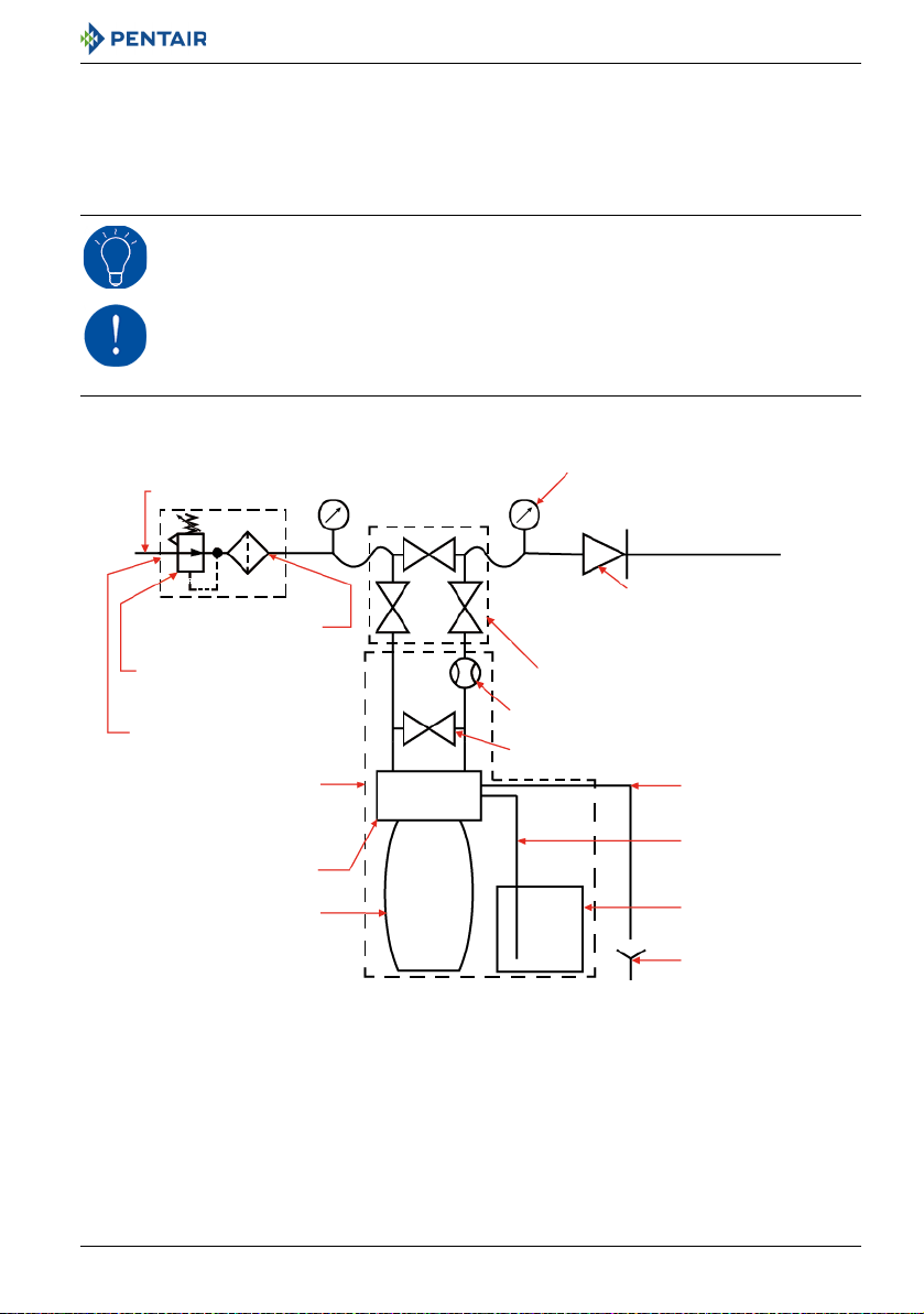
Main inlet
By-pass
User’s line
Valve
Meter
Resin tank
Check valve to prevent water
harm
Pressure gauge
Integrated in the softener
Drain
Brine tank
Brine line
Drain line
Suggested options
Filter cartridge
Pressure regulator
Mixing device
• must meet any local and state codes for site of installation;
• use flexible piping to connect main piping to softener;
• be sure all soldered pipes are fully cooled before attaching plastic valve to the plumbing.
4.5. Softener connection to piping
TIP
To prevent your softener from incoming sediment and iron particles, Pentair recommends
the installation of a 100 μm pre-filter upstream the unit.
MANDATORY
The unit should be installed in accordance with the manufacturer’s recommendations and
meet all applicable plumbing codes.
4.5.1. Block diagram
Ref. MKT-IM-037 / B - 17.12.2018 27 / 90
 Loading...