

Page 1
ETi® 400 HIGH EFFICIENCY HEATER
INSTALLATION AND USER’S GUIDE
FOR YOUR SAFETY - READ BEFORE OPERATING
If you do not follow these instructions exactly, a re or explosion may result, causing property damage,
personal injury or loss of life. For additional free copies of this manual; call USA (800) 831-7133
FOR Y OUR SAFETY - This product must be installed and serviced by authorized personnel, qualified
in pool/spa heater installation. Improper installation and/or operation can create carbon monoxide gas,
fire or explosion, and flue gases which can cause serious injury, property damage, or death. For indoor
installations, as an additional measure of safety, Pentair Water Pool and Spa, Inc. strongly recommends
installation of suitable Carbon Monoxide detectors in the vicinity of this appliance and in any adjacent
occupied spaces. Improper installation and/or operation will void the warranty.
Improper installation, adjustment, alteration, service
or maintenance can cause property damage,
personal injury or death. Installation and service must
be performed by a qualied installer, service agency
or the gas supplier.
120 / 240 VAC NATURAL GAS / LP GAS
Model Natural
ETi® 400 NA - ASME 461113
WHAT TO DO IF YOU SMELL GAS
• Do not try to light any appliance.
FOR
YOUR
• Do not touch any electrical switch; do not use any phone in your building.
• Immediately call your gas supplier from a neighbor’s phone.
Follow the gas supplier’s instructions.
• If you cannot reach your gas supplier, call the re department.
SAFETY
DO NOT store or use gasoline or other ammable vapors and liquids in the vicinity
of this or other appliances.
OWNER:
Retain For
Future
Reference
1620 Hawkins Ave., Sanford, NC 27330
10951 W. Los Angeles Ave., Moorpark, CA 93021
Pentair Water Pool and Spa, Inc.
• (800) 831-7133 or (919) 566-8000
• (800) 831-7133 or (805) 553-5000
Page 2

ETi 400 High Efficiency Pool and Spa Heater Installation and User’s Guide Rev. E 3/2020
Customer Service and Technical Support
2
Customer Service and Technical Support
If you have questions about ordering Pentair Water Pool and Spa, Inc. replacement parts, and
pool products, please call:
Phone: (800) 831-7133
Fax: (800) 284-4151
(8 AM to 7:30 PM Eastern Time/Pacific Time)
Web sites: www.pentair.com
P/N 475349 Revision E. 3/2020
Page 3

Contents
Contents
Warning and Safety Information ............................................................................... 5
Important Notices ........................................................................................................................................... 5
Heater Application Information ....................................................................................................................... 5
Code Requirements ........................................................................................................................................ 6
Consumer Information and Safety Information ............................................................................................... 6-8
General Specifications .................................................................................................................................... 9
Heater Identication Information .............................................................................. 9
Section 1. Operation Instructions .............................................................................. 10
Operator Control Panel ................................................................................................................................... 10-11
Basic System Operation ................................................................................................................................. 11
Heater DSI Electronic Ignition Lighting/Operation ...................................................................................... 11
Start-Up Operation .................................................................................................................................... 12
Putting the Heater into Service .................................................................................................................. 12
Heater Operating Instructions .................................................................................................................... 13
To Turn Off Gas to the Appliance ................................................................................................................... 13
Safety Controls (Air Flow Switches, Water Pressure Switches, Hight Limit Shut-Off Switches) .................... 14-15
(Stack Flue Sensor, Thermal Fuse, Float Switch)
Ignition Module Operation .......................................................................................................................... 15
3
Section 2. Installation ................................................................................................. 16
Heater Description .......................................................................................................................................... 16
Putting the Heater into Service ....................................................................................................................... 16
Sequence Of Operation .................................................................................................................................. 17
Specifications ................................................................................................................................................. 17-18
Plumbing Connections .................................................................................................................................... 19
Water Connections ......................................................................................................................................... 19
Multiple Heater Connections .......................................................................................................................... 20
Valves ............................................................................................................................................................. 21
Manual By-Pass ............................................................................................................................................. 21
Below Pool Installation ................................................................................................................................... 21
Gas Connections ............................................................................................................................................ 22
Gas Pipe Sizing ............................................................................................................................................. 22
Gas Pressure Testing ..................................................................................................................................... 23
Checking Gas Pressure Through Gas Control Valve ..................................................................................... 23
Sediment Traps .............................................................................................................................................. 24
Outdoor Installation (US and Canada) ........................................................................................................... 24-26
Outdoor Installation Venting Guidelines .................................................................................................... 26
Heater Clearances - Outdoor .................................................................................................................... 28
Indoor Venting — General Requirements (Category IV Vertical and Horizontal requirements) .................... 28
Heater Clearances — General Requirements (Indoor and Outdoor Installation for US and Canada) ........ 28
Direct Air Intake Cover ................................................................................................................................... 28
Combustion Air Supply ................................................................................................................................... 29
Air Supply Requirements Guide for the ETi 400 Heater ............................................................................. 29
Direct Air Intake Exhaust Duct using 4-inch PVC Pipe (Indoor Installation) ............................................... 30-36
Direct Air Intake Kit Installation (Combustion Air Supply) ........................................................................... 31
Corrosive Vapors and Possible Causes ......................................................................................................... 32
Horizontal or Vertical Venting (Category IV) - Positive Pressure .................................................................. 33
Vent Installation (Indoor Installation for U.S. or Outdoor Shelter for Canada) ................................................ 34
Direct Vent Requirements .............................................................................................................................. 34-35
Rev. E 3/2020 ETi 400 High Efficiency Pool and Spa Heater Installation and User’s Guide
Page 4

ETi 400 High Efficiency Pool and Spa Heater Installation and User’s Guide Rev. E 3/2020
4
Contents
Contents
Section 2. Installation (Continued) .............................................................................. 38
Vent Installation - Indoor Installation (US and Canada) ................................................................................. 36
Garage or Utility Room Installation (Vent Installtion - Indoor Installation US and Canada) ............................ 37
Final Installation Check .................................................................................................................................. 37
Condensate Management (Maintenance, Condensate Neutralizer Cartridger Drain/Tubing Installation) ...... 38
Electrical Connections .................................................................................................................................... 39
Bonding ..................................................................................................................................................... 39
120 VAC / 240 VAC Wiring ......................................................................................................................... 40
Remote Control Connections ......................................................................................................................... 41
Fireman’s Switch Connection ......................................................................................................................... 41
Heater Connection Wiring Diagram ................................................................................................................ 42
Heater Ladder Wiring Diagram ....................................................................................................................... 43
Section 3. Troubleshooting ........................................................................................ 44
Initial Troubleshooting and Error / Fault Codes .............................................................................................. 44
Initial Troubleshooting Chart ........................................................................................................................... 45
Heater Will Not Fire A .................................................................................................................................. 46
Heater Will Not Fire B .................................................................................................................................. 47
Diagnostics LEDs: PS, HLS, TF, IGN, AFS, AG1, AG2, FS ....................................................................... 48-52
Burner Troubleshooting .................................................................................................................................. 53
Heat Exchanger Troubleshooting ................................................................................................................... 53
Operator Control Panel Displays RNC Code .................................................................................................. 53
Section 4. Maintenance and Care Instruction .......................................................... 54
Care and Maintenance ...................................................................................................................... 54
TitanTough Heat Exchanger Assemblies Annual Inspection ............................................................ 54
Burner Spark Electrode and Flame Sensor Rod Annual Inspection ................................................. 55
Pressure Relief Valve (50 psi)........................................................................................................... 55
After Start-Up .................................................................................................................................... 56
Spring and Autumn ....................................................................................................................... 56
Winter Operation and Winterization .............................................................................................. 56
Return the Heater to Service............................................................................................................. 57
Maintaining Pool Temperature .......................................................................................................... 57
Energy Saving Tips ....................................................................................................................... 57
Chemical Balance ............................................................................................................................. 58-59
Section 5. Heater Replacement Parts........................................................................ 60-66
Heater Replacement Parts List ......................................................................................................... 61
General Replacement Parts .............................................................................................................. 61
Heater Heat Exchanger and Blower Assemblies Replacement Parts............................................... 64
Heater Manifold Assembly - Inlet and Outlet Assembly Replacemant Parts .................................... 64
Heater Condensate and Exhaust Assembly Replacement Parts ...................................................... 65
Heater Operator Control Panel Assembly Replacement Parts ......................................................... 66
Page 5
Warning and Safety Instructions
Warning and Safety Instructions
IMPORTANT SAFETY INSTRUCTIONS
READ AND FOLLOW ALL INSTRUCTIONS
SA VE THESE INSTRUCTIONS
®
400 High Efficiency Pool and Spa Heater
ETi
Thanks you for choosing the Pentair ETi
of your new heating system, and correct chemical maintenance of the water will ensure years of heater operation. The
ETi 400 High Eciency heater is equipped with Pentair advanced heater technology which includes a multifunction
temperature controller to continuously monitor the heater for proper operation. ETi 400 High Eciency heaters are
designed with direct spark ignition (DSI) for on demand heat, which eliminates the need for a standing pilot.
SPECIAL INSTRUCTIONS T O OWNER: Retain this manual for future reference. This instruction manual provides
operating instructions, installation and service information for the heater. READ AND REVIEW THIS MANUAL
COMPLETELY, it is very important that the owner/installer read and understand the section covering installation
instructions, and recognize the local and state codes before installing the ETi 400 High Eciency heater. Its use will
reduce service calls and chance of injury and will lengthen product life. History and experience has shown that most
heater damage is caused by improper installation practices.
IMPORTANT NOTICES
®
400 High Eciency Pool and Spa Heater. With proper installation and service
5
For the installer and operator of the ETi 400 High Eciency Heater: The manufacturer’s warranty may be void
if, for any reason, the heater is improperly installed and/or operated. Be sure to follow the instructions set forth in this
manual. If you need any more information, or if you have any questions regarding to this pool heater, please contact
Pentair Water Pool and Spa Customer Support at (800) 831-7133.
HEATER APPLICATION INFORMATION
The ETi 400 Heater is sold with a limited factory warranty. Pentair Water Pool and Spa high standards of excellence
include a policy of continuous product improvement resulting in your advanced technology pool and spa heater. Pentair
reserves the right to make improvements which change the specications of the heater without incurring an obligation
to update the current heater equipment.
The ETi 400 Heater is designed for the heating of chlorine, bromine or salt system swimming pools and spas. The heater
should never be employed for use as space heating boilers or general purpose water heaters. The manufacturer’s warranty
may be void if, for any reason, the heater is improperly installed and/or operated. Be sure to follow the instructions set
forth in this manual.
CODE REQUIREMENTS
Installation must be in accordance with all local codes and/or the latest edition of the National
Fuel Gas Code, ANSI Z223.1 and the latest edition of the National Electrical Code, NFPA 70
(US).
Installation in Canada must be in accordance with the latest CAN/CGA-B149.1 or .2 and CSA
C22.1 Canadian Electric Code, part 1.
The heater, when installed, must be electrically grounded and bonded in accordance with local
codes, or, in absence of local codes, with the National Electrical Code, ANSI/NFPA70 (US) or
in Canada in accordance with the Canadian Electric Code, part 1 as applicable.
The ETi 400 Pool Heater meets the requirements of the ASME Boiler and Pressure Vessel Code.
Rev. E 3/2020 ETi 400 High Efficiency Pool and Spa Heater Installation and User’s Guide
Page 6
ETi 400 High Efficiency Pool and Spa Heater Installation and User’s Guide Rev. E 3/2020
6
Warning and Safety Instructions
CONSUMER INFORMATION AND SAFETY
WARNING
The U.S. Consumer Product Safety Commission warns that elevated water temperature can be hazardous.
See below for water temperature guidelines before setting temperature.
1. Spa or hot tub water temperatures should never exceed 104° F (40° C). A temperature of 100° F (38° C) is considered
safe for a healthy adult. Special caution is suggested for young children.
2. Drinking of alcoholic beverages before or during spa or hot tub use can cause drowsiness which could lead to
unconsciousness and subsequently result in drowning.
3. Pregnant women beware! Soaking in water above 102° F (39° C) can cause fetal damage during the rst three
months of pregnancy (resulting in the birth of a brain-damaged or deformed child). Pregnant women should stick
to the 100° F (38° C) maximum rule.
4. Before entering the spa or hot tub, the user should check the water temperature with an accurate thermometer. Spa
or hot tub thermostats may error in regulating water temperatures by as much as 4° F (2.2° C).
5. Persons with a medical history of heart disease, circulatory problems, diabetes or blood pressure problems should
obtain their physician’s advice before using spas or hot tubs.
6. Persons taking medication which induce drowsiness, such as tranquilizers, antihistamines or anticoagulants should
not use spas or hot tubs.
WARNING
Should overheating occur or the gas supply fail to shut off, turn off the manual gas control valve to the heater.
Do not use this heater if any part has been under water. Immediately call a qualified service technician to
inspect the heater and to replace any part of control system and gas control which has been under water.
WARNING
The U.S. Consumer Product Safety Commission warns that carbon monoxide is an “invisible killer”. Carbon monoxide
is a colorless and odorless gas.
1. Carbon monoxide is produced by burning fuel, including natural gas and propane.
2. Proper installation, operation and maintenance of fuel-burning appliances in the home is the most important
factor in reducing carbon monoxide poisoning.
3. Be sure that fuel burning appliances such as heaters are installed by professionals according to manufacturer’s
instructions and codes.
4. Always follow the manufacturer’s directions for safe operation.
5. Have the heating system (including vents) inspected and serviced annually by a trained service technician.
6. Examine vents regularly for improper connections, visible cracks, rust or stains.
7. Install battery-operated carbon monoxide alarms. The alarms should be certied to the requirements of the most
recent UL, IAS, CSA and IAPMO standard for carbon monoxide alarms. Test carbon monoxide alarms regularly
and replace dead batteries.
Page 7
Warning and Safety Instructions
SAFETY INFORMATION
The ETi® 400 High Efficiency Pool and Spa Heater is designed and manufactured to provide many years of safe and reliable
service when installed, operated and maintained according to the information in this manual. Throughout this manual, safety
warnings and cautions are identified by the “ “ symbol. Be sure to read and comply with all of the warnings and cautions.
DANGER —
CARBON MONOXIDE GAS IS DEADLY
READ OWNERS MANUAL COMPLETELY BEFORE OPERATING
THIS PRODUCT MUST BE INSTALLED AND SERVICED BY A PROFESSIONAL SERVICE TECHNICIAN,
QUALIFIED IN POOL HEATER INSTALLATION. Some jurisdictions require that installers be licensed.
Check with your local building authority about contractor licensing requirements. Improper installation
and/or operation could create carbon monoxide gas and flue gases which could cause serious injury or
death. Improper installation and/or operation will void the warranty.
Exhaust from this pool heater contains toxic levels of carbon monoxide, a dangerous, poisonous gas you
cannot see or smell. Symptoms of carbon monoxide exposure or poisoning include dizziness, headache,
nausea, weakness, sleepiness, muscular twitching, vomiting and inability to think clearly. IF YOU
EXPERIENCE ANY OF THE ABOVE SYMPTOMS, IMMEDIATELY TURN OFF THE POOL HEATER, LEAVE
THE VICINITY OF THE POOL OR SPA AND GET INTO FRESH AIR IMMEDIATELY. THE POOL HEATER
MUST BE THOROUGHLY TESTED BY A GAS PROFESSIONAL BEFORE RESUMING OPERATION.
EXCESSIVE CARBON MONOXIDE EXPOSURE CAN CAUSE BRAIN DAMAGE OR DEATH.
• NEVER use this pool heater indoors without specified ventilation system (and properly installed
vent pipe).
7
• NEVER use this pool heater in the home or in partly enclosed areas (such as garages), unless the
specified ventilation system is used. If used outdoors, install far from open windows, doors, vents
and other openings.
• Pentair strongly recommends that all vents, pipes and exhaust systems be initially and periodically
tested for proper operation. This testing can be accomplished by using a hand-held carbon
monoxide meter and/or by consulting with a gas professional.
• Pool heaters must be used in conjunction with carbon monoxide detectors installed near the pool
heater. The carbon monoxide detectors must be periodically inspected for proper operation so as
to insure continued safety. Broken or malfunctioning carbon monoxide detectors must be replaced
immediately.
WARNING — FOR YOUR SAFETY
This product must be installed and serviced by a professional service technician, qualified in pool
heater installation. Some jurisdictions require that installers be licensed. Check with your local building
authority about contractor licensing requirements. Improper installation and/or operation could create
carbon monoxide gas and flue gases which could cause serious injury or death. Improper installation
and/or operation will void the warranty.
WARNING — This heater is equipped with an unconventional gas control valve that is factory set at a
pressure of -.2 inches wc. Improper installation, adjustment, alteration, service or maintenance
can cause property damage, personal injury or loss of life. Installation or service must be performed
by a qualified installer, service agency or the gas supplier. If this control is replaced, it must be
replaced with an identical control.
Do not attempt to adjust the gas flow by adjusting the regulator setting.
Rev. E 3/2020 ETi 400 High Efficiency Pool and Spa Heater Installation and User’s Guide
Page 8
ETi 400 High Efficiency Pool and Spa Heater Installation and User’s Guide Rev. E 3/2020
8
Warning and Safety Instructions
SAFETY INFORMATION (continued)
WARNING — Risk of fire or explosion from incorrect fuel use. Do not try to run a heater set up for natural gas on propane
gas or vice versa. Only qualified service technicians should attempt to convert heater from one fuel to the other.
Do not attempt to alter the rated input or type of gas by changing the orifice. If it is necessary to convert to a
different type of gas, consult your Pentair dealer. Serious malfunction of the burner can occur which may result
in loss of life. Any additions, changes, or conversions required in order for the appliance to satisfactorily meet
the application needs must be made by a Pentair dealer or other qualified agency using factory specified and
approved parts. The heater is available for use with natural gas or LP (propane) gas only. It is not designed to
operate with any other fuels. Refer to the nameplate for the type of gas the heater is equipped to use.
• Use heater only with the fuel for which it is designed.
• If an LP (propane) gas conversion is necessary, this MUST be done by a qualified professional service
technician qualified in pool heater installation or by qualified gas supplier before the herater is operational.
WARNING — Risk of fire or explosion from flammable vapors. Do not store gasoline, cleaning fluids, varnishes, paints,
or other volatile flammable liquids near heater or in the same room with heater.
WARNING — Risk of explosion if unit is installed near propane gas storage. Propane (LP) gas is heavier than air. Consult
local codes and fire protection authorities about specific installation requirements and restrictions. Locate the
heater away from propane gas storage and filling equipment as specified by the Standard for the Storage and
Handling of Liquefied Petroleum Gases, CAN/CSA B149.2 (latest edition) or ANSI/NFPA 58 (latest edition).
WARNING — Risk of fire, carbon monoxide poisoning, or asphyxiation if exhaust venting system leaks. Only qualified
service technicians should attempt to service the heater, as leakage of exhaust products or flammable gas may
result from incorrect servicing.
WARNING — Risk of asphyxiation if exhaust is not correctly vented. Follow venting instructions exactly when installing
heater. Do not use a draft hood with this heater, as the exhaust is under pressure from the burner blower and
a draft hood will allow exhaust fumes to blow into the room housing the heater. The heater is supplied with an
integral venting system for indoor installation. Canada: In Canada, this pool heater can only be installed
outdoors or in an enclosure that is not normally occupied and has no openings directly into occupied areas.
See Page 25 - 29 for enclosure venting requirements.
CAUTION — Label all wires prior to disconnection when servicing controls. Wiring errors can cause improper and
dangerous operation. Wiring errors can also destroy the control board.
• Connect heater to 120 or 240 Volt, 60 Hz., Single Phase power only.
• Verify proper operation after servicing.
• Do not allow children to play on or around heater or associated equipment.
• Never allow children to use the pool or spa without adult supervision.
DANGER
CARBON MONOXIDE GAS IS DEADLY – Exhaust from this pool heater contains toxic levels of carbon monoxide, a dangerous,
poisonous gas you cannot see or smell.
Page 9
Warning and Safety Instructions
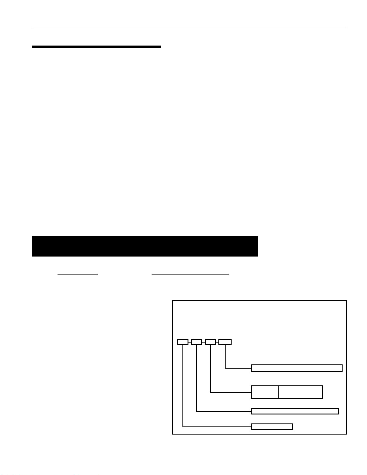
ETI 400 NA ASME
ETi = High Efficiency
FUEL TYPE =
CONSTRUCTION =
MODEL SIZE = BTU INPUT in 1000 of BTU / HR
H. I. N.
HEATER IDENTIFICATION NUMBER
ID DESIGNATOR FOR PENTAIR WATER POOL AND SPA, ETi HEATER
NA = NATURAL GAS
Example:
1 2 3 4
ASME = COMMERCIAL MODEL
GENERAL SPECIFICATIONS
NOTICE
• Combustion air contaminated by corrosive chemical fumes can damage the heater and will void the warranty.
• The Combination Gas Control Valve on this heater diers from most appliance gas controls. If it must be
replaced, for safety reasons replace it only with an identical gas control valve.
• The heater’s access side panels must be in place to provide proper ventilation and to avoid water intrusion. Do
not operate the heater for more than ve (5) minutes with the side panels removed.
• This heater is certied by CSA International as complying with the Standard for Gas Fired Pool Heaters,
ANSI Z21.56/CSA 4.7, and is intended for use in heating fresh water swimming pools or spas.
®
• The ETi
It should NOT be used as a space heating boiler, or general purpose water heater.
• The heater should be located in an area where leakage of the heater or connections will not result in damage to
the area adjacent to the heater or to the structure. When such locations cannot be avoided, it is recommended
that a suitable drain pan, adequately drained, be installed under the heater. The pan must not restrict air ow.
• The heater may not be installed within 5 ft. (1.5M ) of the inside surface of a pool or spa unless it is separated
by a solid fence, wall or other permanent barrier.
• In the United States, installation must be in accordance with local codes and the most recent edition of the
National Fuel Gas Code, ANSI Z223.1/NFPA-54. The Code can be obtained from: National Fire Protection
Association 1 Batterymarch Park Quincy, MA 02169 www.nfpa.org
• In Canada, install the heater in accordance with local codes and the most recent edition of the Natural Gas and
Propane Installation Code, CAN/CSA B149.1.
400 Heater is designed for the heating of chlorine, bromine or salt system swimming pools and spas.
9
Heater Identification Information (HIN)
To identify the heater, see rating plate on the inner front panel of the heater. There are two designators for each heater,
one is the Model Number and the other is the Heater Identication Number (HIN).
Heater Identification Number (HIN)
The following example simplifies the identification system:
1) ETi
2) Model Size : (400) : Input rating (Btu/hr)
X 1000
3) Fuel Type : NA = Natural gas
4) Construction : ASME = Commercial Model
Rev. E 3/2020 ETi 400 High Efficiency Pool and Spa Heater Installation and User’s Guide
Page 10
ETi 400 High Efficiency Pool and Spa Heater Installation and User’s Guide Rev. E 3/2020
10
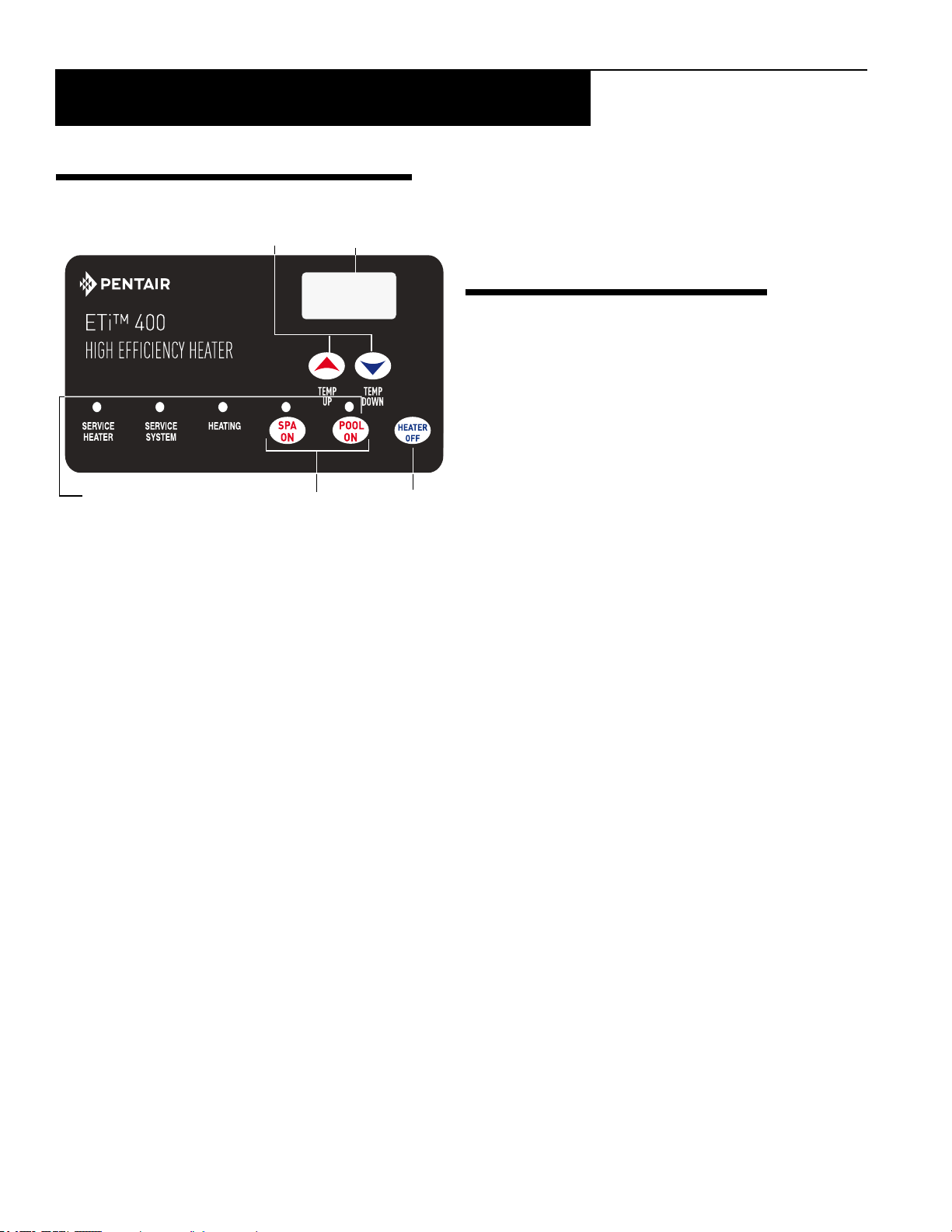
Temperature
Up and Down
Digital Temperature
Display
System Operation
Indicator Lights
Dual Temperature
Controls
Heater "OFF"
Switch
Section 1: Operation Instructions
Section 1: Operation Instructions
OPERATOR CONTROL PANEL
TEMPERATURE SETTING
The ETi
®
400 Heater is shipped factory set at 70° F (35°
C) for pool mode and 95° F (21° C) for spa mode. Using
the up and down arrows, you can set the thermostats to a
minimum temperature of 65° F (18.3° C), or a maximum
of 104° F (40° C).
The heater operator controls are as follows:
POOL ON Press this button to control the heater operation by the pool temperature setting.
SPA ON Press this button to control the heater operation by the spa temperature setting.
HEATER OFF Press this button to switch o the heater.
▲ TEMP Press this button to raise the temperature setting.
▼ TEMP Press this button to lower the temperature setting.
To toggle the display between degrees Centigrade (°C) and degrees Fahrenheit (°F):
1. Press the HEATER OFF button to switch the heater OFF.
2. Press ▲ TEMP or ▼ TEMP for 5 seconds. The display will ash once and change modes (°C to °F or vice versa).
3. Press the HEATER OFF button to switch the heater ON.
When either the ▲ TEMP or ▼ TEMP buttons are depressed, the digital display will indicate the temperature setting.
After ve seconds, the display will return to the actual pool/spa temperature.
In addition to the digital temperature display, there are ve indicator lights:
The POOL ON light indicates the pool water temperature is controlling the heater operation.
The SPA ON light indicates the spa water temperature is controlling the heater operation.
The HEATING light comes on and stays on when the heater’s burner chamber is ring. This light should be on whenever
the burner is on. This light blinks when the heater is calling for heat but not ring. If this light is on but the burner fails
to come on, one of the “service” lights should come on, indicating a fault in the system.
The SER VICE SYSTEM light indicates that there is insucient water ow to the heater. If the pump is operating, this
usually indicates that the lter and/or skimmers should be cleaned (some lters may require back-washing). If the light
remains on after the lter/skimmers have been serviced, the system should be checked by a qualied service technician.
The SER VICE HEATER light indicates a fault in the heater or its controls. If this light comes on, shut down the heater
(See TO TURN OFF GAS T O THE APPLIANCE on page 13), and have a qualied service technician check the system.
Page 11
Section 1: Operation Instructions
11
OPERATOR CONTROL PANEL
VIEW FAULT CODES: Press the POOL ON button and the ▲ TEMP button to view the last fault code.
Press the ▲ TEMP button to scroll up to view the previous 4th. fault codes. The next message displayed after the
5th. fault code is END.
VIEW STACK FLUE GAS TEMPERATURE: Press and hold the POOL ON (or SPA ON) button for more than 5
seconds to view the current Stack Flue Gas temperature. Each heat exchange has one temperature sensor (SF1 and
(SF2), the SF1 temperature is displayed on the heater’s LCD with a dot on the upper left corner of the LCD. Scroll
up or down to display the SF2 current temperature and the dot will not be displayed on the LCD.
BASIC SYSTEM OPERATION
Start the pump. Be sure the pump is running and primed to close the water pressure switch and
supply power to heater. Be sure the pool and/or spa is properly filled with water. Follow the Lighting
and Operating instructions below.
WARNING
Risk of explosion or fire causing burns or death if safety interlocks are disabled. DO NOT attempt to operate heater when
SERVICE HEATER light is on or if blower or burner will not start. Instead, follow instructions under “To Switch Off Gas to the
Appliance,” and call a qualified service technician to repair unit.
HEATER DSI ELECTRONIC IGNITION LIGHTING/OPERATION
FOR YOUR SAFETY: READ BEFORE LIGHTING
WARNING
If you do not follow these instructions exactly, a fire or explosion may result
causing property damage, personal injury or loss of life.
Do not attempt to light the heater if you suspect a gas leak. Lighting the heater
can result in a fire or explosion which can cause personal injury, death, and
property damage.
Rev. E 3/2020 ETi 400 High Efficiency Pool and Spa Heater Installation and User’s Guide
Page 12

ETi 400 High Efficiency Pool and Spa Heater Installation and User’s Guide Rev. E 3/2020
12
Section 1: Operation Instructions
BASIC SYSTEM OPERATION (CONTINUED)
START-UP AND OPERATION
START-UP AND SHUTDOWN INSTRUCTIONS ARE ON THE LABEL ATTACHED TO THE INSIDE COVER OF THE APPLIANCE
WATER CONNECTION PANEL.
BEFORE START-UP
A. This appliance does not have a pilot. It is equipped
with an ignition device which automatically lights the
burners. DO NOT try to light the burners by hand.
B. BEFORE OPERATING, smell all around the appliance
area for gas. Be sure to smell next to the oor because
some gas is heavier than air and will settle on the oor.
WHAT TO DO IF YOU SMELL GAS
– Do not try to light any appliance.
– Do not touch any electrical switch; do not use any phone
in your building.
– Immediately call your gas supplier from a neighbor’s
phone. Follow the gas supplier’s instructions.
– If you cannot reach your gas supplier, call the Fire
Department.
C. Use only your hand to turn the gas control on or o.
Never use tools. If you cannot change the ON/OFF
setting by hand, don’t try to repair it, call a qualied
service technician. Forced or attempted repair may result
in a re or explosion.
D. Do not use this heater if any part has been under water.
Immediately call a qualied service technician to inspect
the heater and to replace any part of the control system
and any gas control which has been under water.
E. Do not operate the pool heater unless the pool or spa is
properly lled with water.
F. Before operating the appliance for the rst time or
after it has been o for an extended time, perform the
following checklist:
1. Remove debris or other articles from inside the heater
and the area around the heater and its exhaust vent.
Make sure the ventilation openings are clear of debris
or obstruction. For installations in an enclosed space,
make sure openings for combustion and ventilation
air are unobstructed.
2. Keep heater area clear and free from combustibles,
ammable liquids and chemicals.
3. Check that all water connections are tight.
4. Water must be owing through the heater during
operation. Make sure that pool/spa is lled with water
and have pump operating. Check that water ow is
unobstructed from the appliance. When operating
for the rst time or after an extended shut-down, run
lter pump for several minutes to clear all air from
the system.
PUTTING THE HEATER INTO SERVICE
If the heater’s Water Pressure Switches (PS) are below or above the water level by 1 ft (30 cm), after the heater
installation the Water Pressure Switch setting should be adjusted. See WATER PRESSURE SWITCH, in SAFETY
CONTROLS on page 14.
Note: Before putting the heater into service for the rst time, follow the instructions under BEFORE START-UP
on page 12. Check for proper operation of the heater by following the steps under OPERATING INSTRUCTIONS
on page 13. Damage to equipment caused by improper installation or repair will void the warranty.
Page 13
Section 1: Operation Instructions
HEATER OPERATING INSTRUCTIONS
1. STOP! Read the safety information on (page 12).
2. Set both pool and spa thermostats to the lowest settings.
3. Turn o all electric power to the appliance.
4. This appliance does not have a pilot. It is equipped with an ignition
device which automatically lights the burner. Do not try to light the
burner by hand.
5. Remove the access door panels by unfastening the latch located on each
door, then lift up and out from the bottom of the panel
to remove.
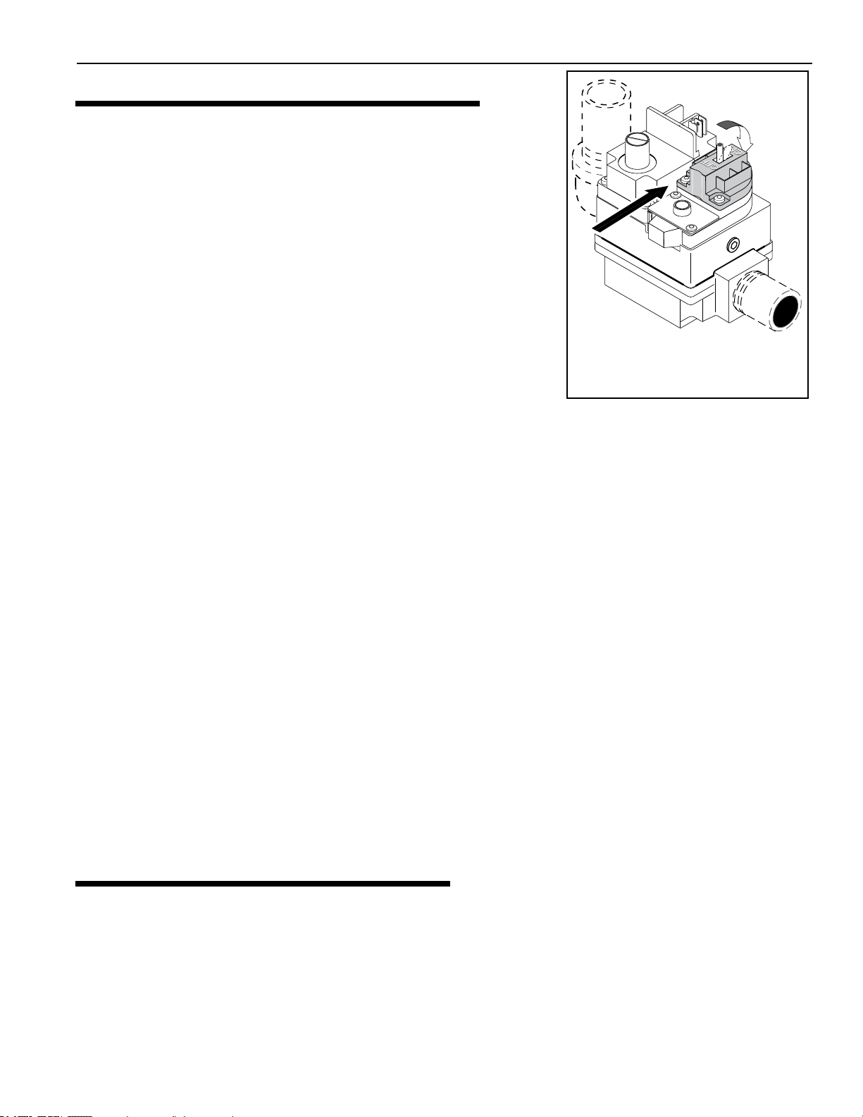
6. Toggle-Style Valve: Pull toggle toward you to turn gas o ,
see Figure 1.
7. Wait ve (5) minutes to clear out any gas. If you then smell gas,
STOP! Follow B in the BEFORE START-UP instructions on page 12.
If you don’t smell gas, go to the next step.
8. Push the toggle switch away from you to switch the gas on.
9. Replace the Door Access Panels. All panels must be in place when operating the heater.
10. Set 3-way valves on inlet and outlet to pool or spa, as appropriate.
11. Turn on all electric power to the appliance.
12. Press either the POOL ON or SPA ON button switch on the operating control.
13. Set the thermostat to desired setting. NOTICE: Setpoint must be above actual water temperature or burner
will not re. See OPERATOR CONTROL PANEL on page 11.
14. The blower should come on immediately, and after about 15 seconds, the burner should re. When operating for
the rst time, the burner may not re on the rst try because of air in the gas line. If it does not re at rst, push the
OFF switch, wait ve minutes, and again push the POOL or SPA ON switch. The burner should re after about 15
seconds. You may have to repeat this until all of the air has cleared the gas line.
15. The burner should re until the pool/spa temperature reaches the desired temperature set on the thermostat. The
blower will continue to run for about 45 seconds after the burner shuts o. If any of the safety interlocks should
open during burner operation, the burner shuts o immediately, but the blower continues to run for about 45
seconds. Should overheating occur or the gas supply fail to shut o, turn o the manual gas control valve to the
appliance.
16. If the appliance will not operate, follow the instructions TO TURN OFF GAS TO THE APPLIANCE below,
and call your service technician or gas supplier.
Gas control is shown
OFF. Push toggle switch
away from you to switch ON.
Figure 1.
13
17. If the electrical power is shut o to the heater while it is running, once power is restored, the heater will power up
with the previous programed settings.
TO TURN OFF GAS TO APPLIANCE
1. Press the OFF button on operating control.
2. Switch o all electric power to the unit.
3. Remove the access door panels.
4. Toggle-Style Valve: Pull toggle toward you to turn gas o, see Figure 1.
5. Replace the Access Door Panels.
Rev. E 3/2020 ETi 400 High Efficiency Pool and Spa Heater Installation and User’s Guide
Page 14
ETi 400 High Efficiency Pool and Spa Heater Installation and User’s Guide Rev. E 3/2020
14
A reference scale is on
the back of pressure switch
Turn star wheel clockwise to raise
pressure set point if water pressure switch is
more than 1 ft (30 cm) below water level
Turn star wheel counterclockwise to lower
pressure set point if pressure switch is more
than 1 ft (30 cm) above water level
Water Pressure
Switch
Star Wheel
Section 1: Operation Instructions
SAFETY CONTROLS
AIR FLOW SWITCH (AFS)
There are two air ow switches, (see Figure 2), designed as a safety device to ensure
the two combustion air blowers (fans) are operating and are monitoring the dierential
(negative) pressure within the blower housing. These air pressure switches are factory
set. The switches (see page 63 #29) are connected upstream of the ignition module.
The ignition module does not operate unless the air ow switches and all safety
switches are closed.
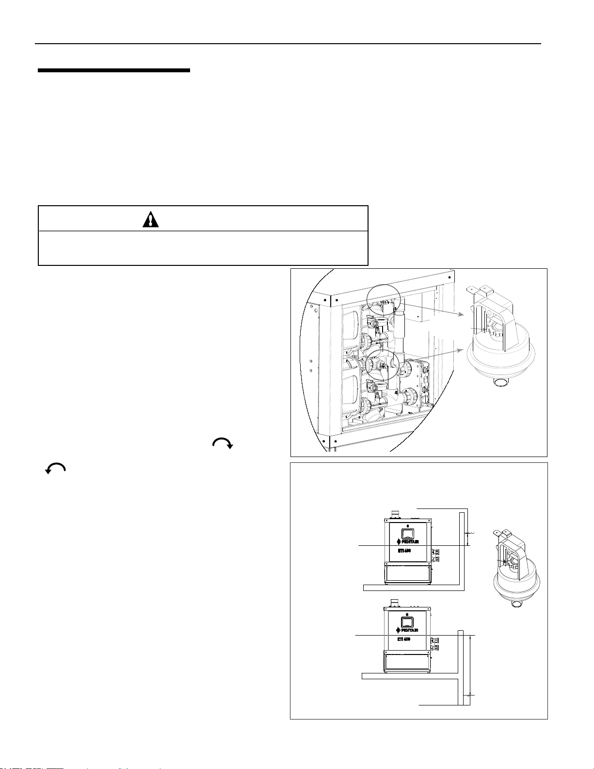
WATER PRESSURE SWITCHES
Hazardous pressure. Do not bypass the Water Pressure Switches or render
it inoperable.
The heater has two Water Pressure switches, see Figure 3.
If the water ow is restricted, the water pressure switches
may prevent the burner from ring and cause the Service
System LED indicator to go on. Note: If the light remains
on after the lter has been serviced, have a qualied
service technician check the system.
For deck-level heater installations, the Water Pressure
switches are factory set at 3.00 psi (20.6 kPa). Note:
See Below Pool Level Installation, on page 21. If the
pressure switches are 1 ft (0.3M) below or above the pool
water level, reset the switches so that it is open when the
pump is o and closed when the pump is running. Turn
the star-wheel on the switch clockwise ( ) to raise
setting (heater below the pool level) and counterclockwise
( ) to lower the setting (heater above the pool
level), see Figure 4. Test each switch after resetting.
WARNING
Figure 2. Air Flow Switch
Water Pressure
Switch
Star Wheel
Figure 3: Water Pressure Switch
NOTICE: When the heater is mounted more than
1 ft (30 m) above or 1 ft (30 cm) below the deck level,
a pressure switch is no longer adequate. A Flow
Switch must be installed instead.
CAUTION! Heater operation with an incorrect water
pressure switch setting, may cause the heater to
operate without sufficient water flow, and may cause
severe heater damage.
HIGH LIMIT SWITCH AND
AUTOMATIC GAS SHUT-OFF
SWITCHES (AG1 AND AG2)
A High Limit Switch (HLS), is a safety device that
opens the electrical circuit and shuts o the heater based
on a water temperature set point within the HLS. The
heater contains two AGS switches and one HLS
switch. The AGS switches are located in the outlet
plumbing assembly, and the HLS switch is located on
the main Inlet/Outlet Header (see page 16).
Figure 4.
Page 15
Section 1: Operation Instructions
SAFETY CONTROLS (continued)
STACK FLUE SENSORS (SF1, SF2)
The heater is equipped with two Stack Flue sensors; one for each heat exchanger. These sensors monitor the stack ue
temperature and if needed will shut down the heater if the stack ue temperature exceeds 170° F (77° C).
THERMAL FUSE
A Thermal Fuse (TF) is a safety protection device that opens the electrical circuit if the temperature reaches 187° F
(86° C). The fuse cannot be reset, it must be replaced. See page 17 for more information.
FLOAT SWITCH
The Float Switch (FS) is a sensing application that shuts down the heater once the condensate level exceeds the
permitted level in the condensate container. See page 17 for more information.
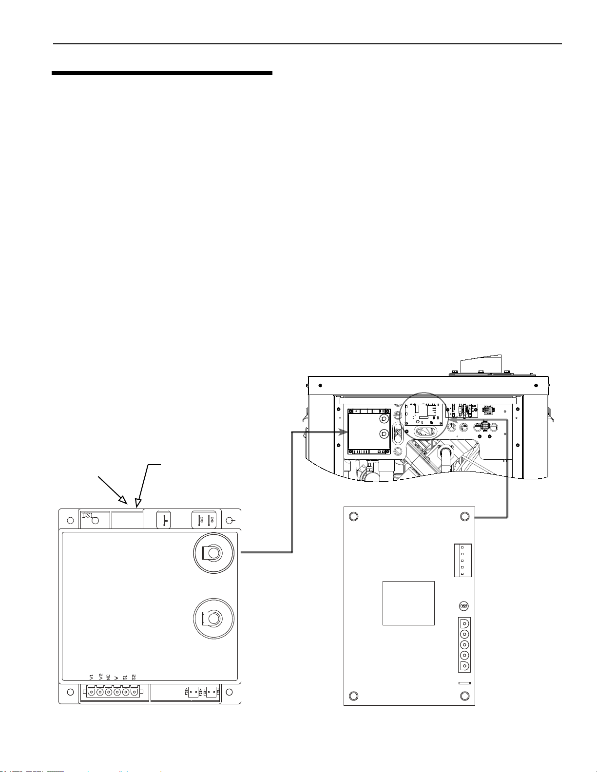
IGNITION MODULE OPERATION
The Ignition Module, (Figure 5), is microprocessor based and operates on 24VAC supplied by the transformer. The
control works in conjunction with a fan control board (Figure 6), and utilizes a microprocessor to continually safely
monitor, analyze, and control the proper operation of the gas ame holder. The module with the presence of the ame
sensor, using ame rectication, allows the heater to operate.
15
Flame Current
Check Point
Diagnostic LED
1 Flash - Air Flow Fault
2 Flashes - Flame No Call for Heat
3 Flashes - Ignition Lockout
Figure 5. Ignition Control Module
Heater left side panel removed
PS1
PS2
TH
START
NC IN
FAN1
FAN2
L1
UNUSED
GND
R 24 VAC
Figure 6. Fan Control Circuit Board
Rev. E 3/2020 ETi 400 High Efficiency Pool and Spa Heater Installation and User’s Guide
Page 16
ETi 400 High Efficiency Pool and Spa Heater Installation and User’s Guide Rev. E 3/2020
16
Section 2: Installation Instructions
Section 2: Installation Instructions
THIS HEATER MUST BE INSTALLED AND SERVICED BY A PROFESSIONAL SERVICE TECHNICIAN,
QUALIFIED IN POOL HEATER INSTALLATION.
Pentair strongly recommends that all vents, pipes and exhaust systems be initially and periodically tested for proper
operation. This testing can be accomplished by using a hand-held carbon monoxide meter and/or by consult-
ing with a gas professional. Pool and spa heaters must be used in conjunction with carbon monoxide detectors
installed near the pool heater. The carbon monoxide detectors must be periodically inspected for proper operation so
as to insure continued safety. Broken or malfunctioning carbon monoxide detectors must be replaced immediately.
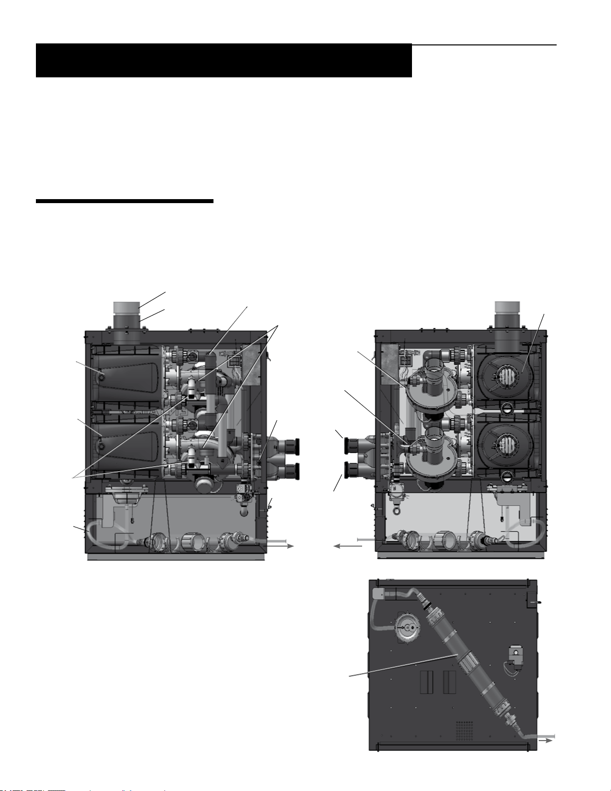
HEATER DESCRIPTION
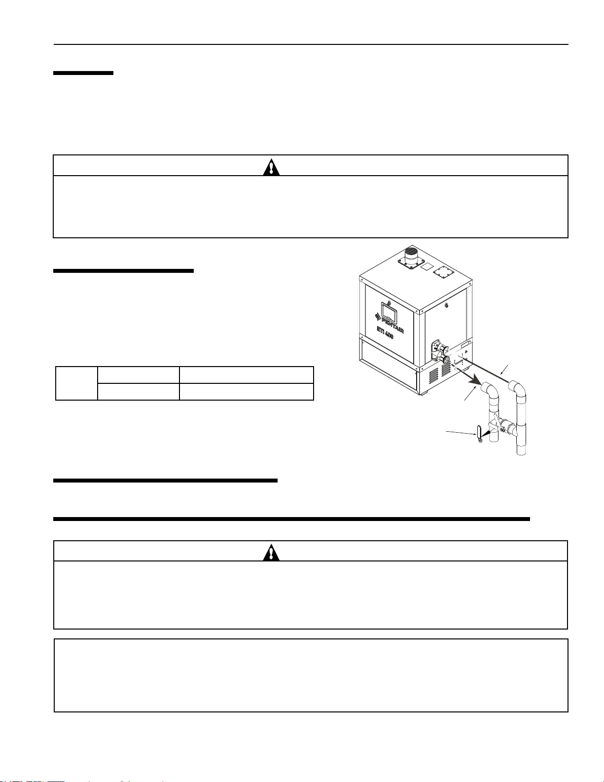
The ETi
®
400 Heater has precisely matched orice plates to meter the air and gas into the mixer. The blower draws the air
and gas through the mixer and forces it into the burner’s ame holder. A sealed TitanTough™ Heat Exchanger surrounds
the ame holder, discharging exhaust gases out the ue (See Figure 7 & 8). Use a 2 in tting to connect to the 2 in PVC
slip unions provided with the heater. The outer manifold remains cool; no heat sinks are required. The heater operator
control panel is located on the side of the heater.
Vent Cap
CPVC Flue
Outlet
Upper Heat
Exchanger
Lower Heat
Exchanger
Auto gas
shut-off
switch
(AGS)
Tubing for
Condensate
Neutralizer
Cartridge
Inlet Plumbing
Assembly
High
Limit
Switch
(HLS)
Electrical
and
Bonding
lug
To drain
Tridicator (Water pressure and
Temperature gauges)
Upper Blower
Assembly
Lower Blower
Assembly
2-in Inlet
Plumbing
Assembly
2-in Outlet
Plumbing
Assembly
To drain
Exhaust
Assembly
Figure 7. ETi® 400 Heater (Left Side View)
Condensate Neutralizer Cartridge
(Optional, P/N 475612 sold separately).
The cartridge may be mounted onto the heater
base for heater outdoor installation.
Figure 8. ETi® 400 Heater (RIght Side View)
Heater Base (Top View)
Page 17
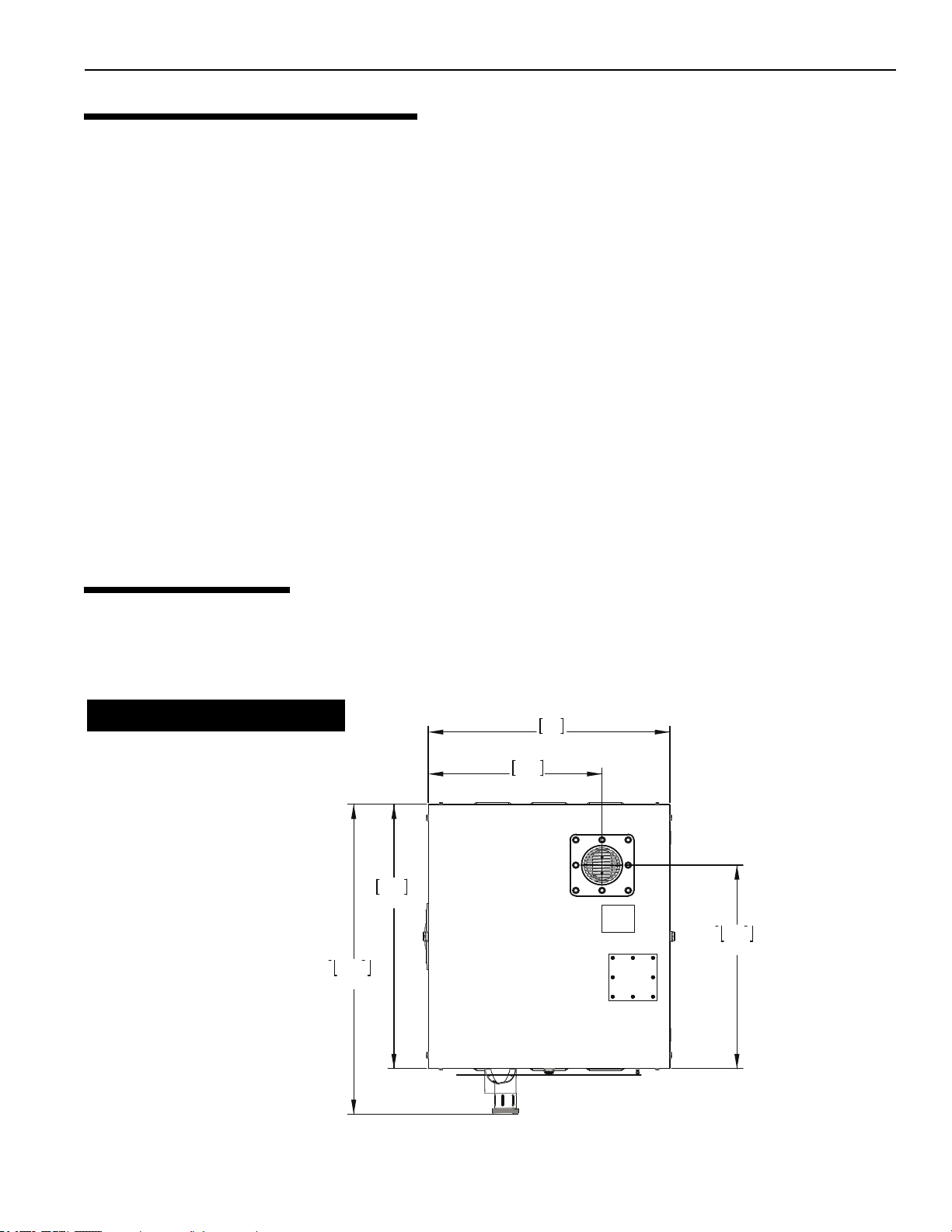
Section 2: Installation Instructions
Heater Top Vie w
762
30.0
863.6
34.0
1012.8
39.9
548.1
21.6
664.9
26.2
17
SEQUENCE OF OPERATION
An electronic temperature sensing thermistor in the manifold adapter inlet controls the heater operation. When the inlet
water temperature drops below the temperature set on the operator control panel, the control board supplies power to
the combustion air blowers through a series of safety interlocks. The heater interlocks consist of:
• the two water pressure switches (PS), which senses that the pump is running,
• the tridicator gauges (2) which monitors the water temperature in degree Fahrenheit and pressure in psi.
• the high limit switch (HLS), which opens if the heat exchanger outlet temperature goes above 135° F (57° C), and
• the two air ow switches (AFS), sense the pressure drop across the air metering orices.
• the two thermal fuses (TF) open if the ue gas temperature reaches 187° F (86° C).
• the automatic gas shut-o (AG1, AG2) switches, which open if the heat exchanger outlet temperature goes above
150° F (66° C).
• the oat switch (FS) which opens if the condensate overows at the oat switch due to blockage in the condensate
drain hose or neutralizer cartridge.
• the stack ue sensors (SF1, SF1), which shut down the heater if the ue gas temperature reaches 170° F (77° C).
The air ow switches (AFS) sense the pressure dierential between both of the air metering orices. As soon as there is
sucient air ow, the AFS closes, completing the circuit to the Fan Conrol board. The gas ignition control then opens
the gas valve and the fuel mixture is ignited by the Direct Spark Ignition (DSI). On a call for heat, the blowers are
energized for 15 seconds, the gas valve opens simultaneously as the direct spark igniters are energized, then ignition
occurs. The heater is equipped with a digital operating control that enables the user to pre-set the desired pool and spa
water temperatures. The control enables the user to select between pool and spa heating, and features a digital display
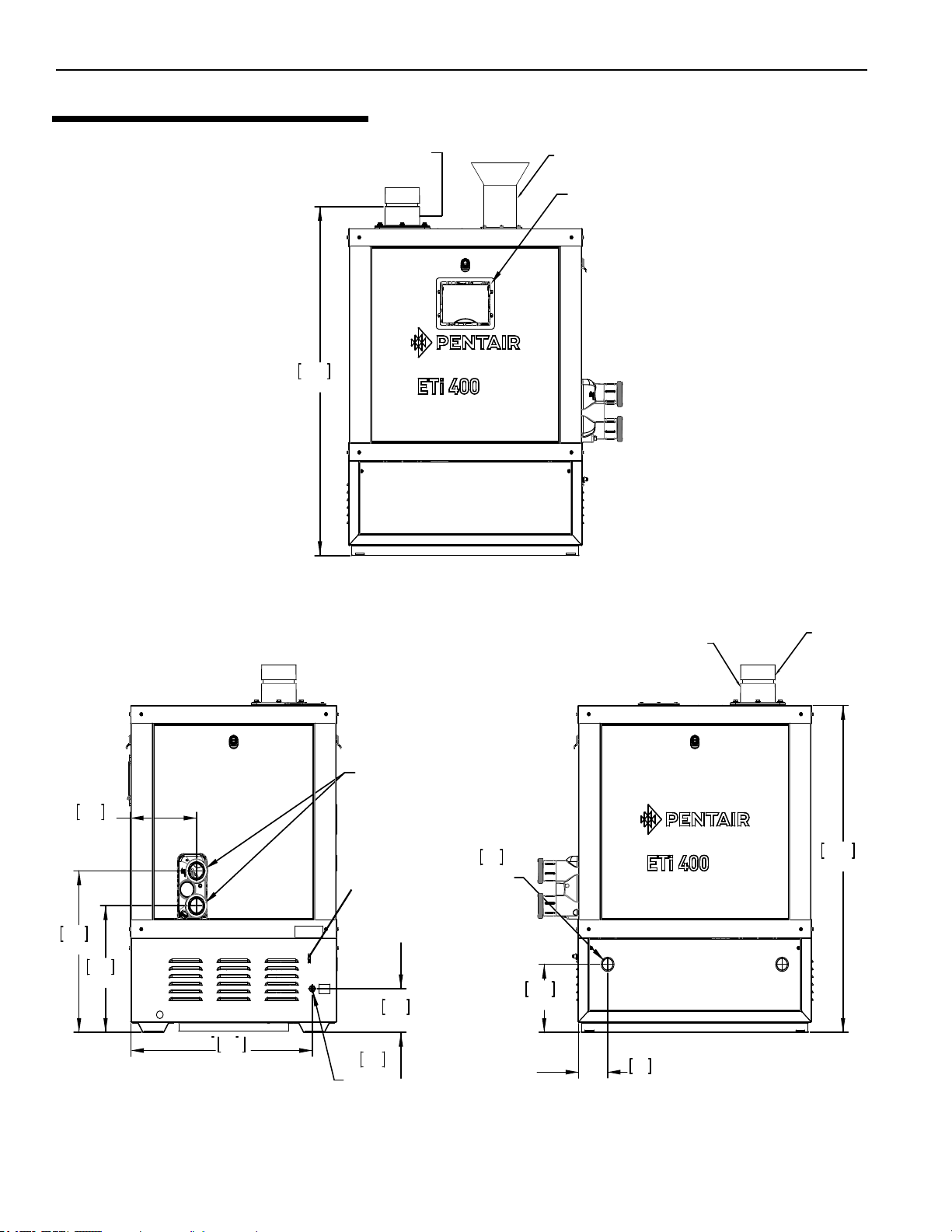
SPECIFICATIONS
The installation instructions contained in this manual are designed for use by qualied personnel only, trained especially
for installation of this type of heating equipment and related components. Some states require installation and repair by
licensed personnel. If this applies in your state, be sure your contractor bears the appropriate license. See Figure 9, 10
& 11 for Outdoor and Indoor installations, dimensions and orientation of the heater.
Dimensions in Millimeters / Inches
Figure 9.
Rev. E 3/2020 ETi 400 High Efficiency Pool and Spa Heater Installation and User’s Guide
Page 18
ETi 400 High Efficiency Pool and Spa Heater Installation and User’s Guide Rev. E 3/2020
18
421.2
16.6
537.3
21.2
243.5
9.6
670.3
26.4
22.2
Ă .88
ELECTRICAL
145.6
5.7
Heater Plumbing Side
2 in WATER INLET
CONNECTIONS
1087.5
42.8
108
4.3
38.1
Ă 1.5
GAS
226.6
8.9
4-IN CPVC FLUE
EXHAUST
SOCKET
1160.5
45.7
CONTROL CONTROL TOUCH
PAD/ DISPLAY
4-IN CPVC FLUE EXHAUST SOCKET
BONDING LUG
Heater Rear View
Heater Front View
4-IN PVC AIR INLET CONNECTION
(INDOOR OPTIONAL KIT)
4-IN PVC VENT CAP
Section 2: Installation Instructions
SPECIFICATIONS (CONTINUED)
Figure 10.
Figure 11.
Page 19
PUMP
FILTER
HEATER
MANUAL
BY-PASS
TO
POOL
GATE
VALVE
FROM
POOL
FROM
FILTER
INLET
OUTLET
Section 2: Installation Instructions
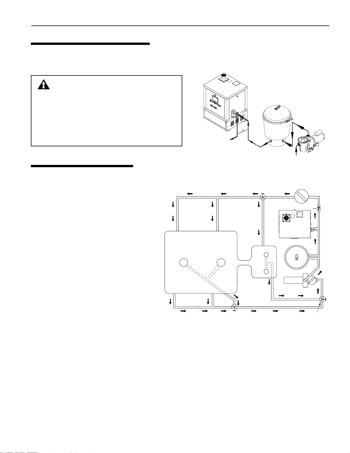
PLUMBING CONNECTIONS
The heater has the unique capability of direct schedule 40 PVC plumbing connections. A set of bulkhead ttings is
included with the heater to ensure conformity with Pentair’s recommended PVC plumbing procedure. Other plumbing
connections can be used. See Figure 12 for plumbing connections.
CAUTION
Before operating the heater on a new installation, turn on
the circulation pump and bleed all the air from the filter
using the air relief valve on top of the filter. Water should
flow freely through the heater. Do not operate the heater
unless water in the pool/spa is at the proper level. If a
manual by-pass is installed, temporarily close it to ensure
that all air is purged from the heater.
Figure 12.
WATER CONNECTIONS
The heater requires proper water ow and pressure
for its operation. See Figure 13 for the recommended
installation. The lter pump discharges to the lter,
the lter discharges to the heater, and the heater
discharges directly to the pool or spa.
A manual bypass valve should be installed before
the heater when the pump ow exceeds 120 GPM
(454 LPM ). See WATER FLOW RATE Table 1
on page 21 for setting of the manual by-pass valve.
Make sure that the outlet plumbing from the heater
contains no shut-o valves or other ow restrictions
that could prevent ow through the heater (except
Main
Drain
Pool
for pool installations as noted below, or winterizing
valves where needed). To switch ow between the
pool and spa, use a diverter valve. Do not use any
valve that can shut o the ow.
Install the chemical feeder downstream of the
heater. Install a chemical resistant one-way check
valve between the heater and the chemical feeder
to prevent back-siphoning through the heater
when the pump is o.
From Pool
Figure 13.
3-Way
Valve
Note: For Multiple Heater installation, see page 20.
NOTICE: If the heater is plumbed in backwards, it will cycle continuously. Make sure piping from lter is not reversed
when installing heater.
Connect the heater directly to 2 in PVC pipe, using the provided unions. Heat sinks are not required. The low thermal mass
of the heater will prevent overheating of the piping connected to the pump even if the heater shuts down unexpectedly.
Occasionally a two-speed pump will not develop enough pressure on the low speed to operate the heater. In this case, run
the pump at high speed only to operate the heater. If this does not solve the problem, do not try to run the heater. Instead,
correct the installation.
Do not operate the heater while an automatic pool cleaner is also operating. If the circulation pump suction is plugged
(for example by leaves), there may not be adequate ow to the heater. Do not rely on the pressure switch in this case.
Rev. E 3/2020 ETi 400 High Efficiency Pool and Spa Heater Installation and User’s Guide
3-Way
Valve
Spa
Chlorinator
Check Valve
Heater
Filter
Pump
3-Way
Valve
19
Page 20
ETi 400 High Efficiency Pool and Spa Heater Installation and User’s Guide Rev. E 3/2020
20
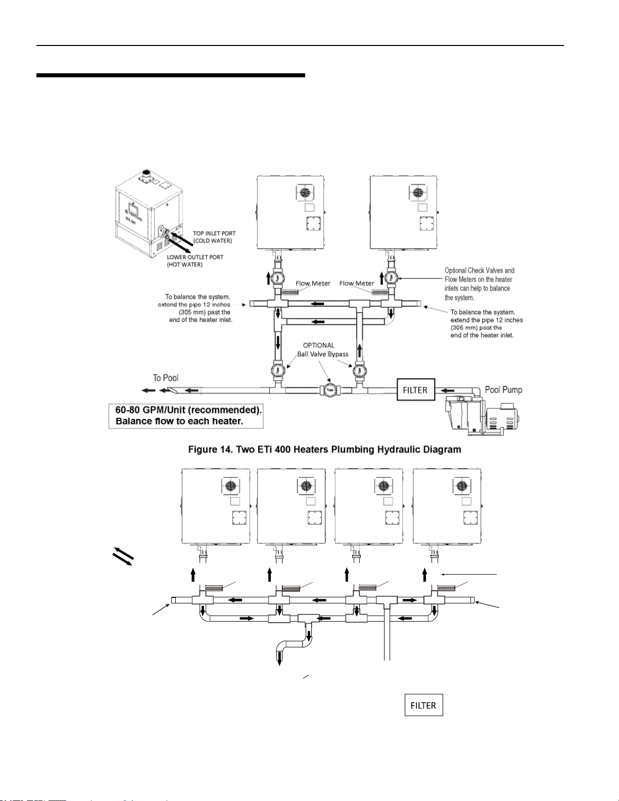
TOP INLET PORT
(COLD WATER)
LOWER OUTLET PORT
(HOT WATER)
Firgue 15. Four ETi 400 Heaters Plumbing Hydraulic Diagram
To balance the system,
extend the pipe 12 inches
(305 mm) past the
end of the heater inlet.
Optional Check Valves and
Flow Meters on the heater
inlets can help to balance
the system.
To balance the system,
extend the pipe 12 inches
(305 mm) past the
end of the heater inlet.
Flow Meter
Flow Meter
Flow Meter
Flow Meter
Section 2: Installation Instructions
MULTIPLE HEATER INSTALLATION
All plumbing on multiple heater installations must be done in parallel. See Figure 14 and Figure 15.
To prevent heater overheating and to ensure heater longevity, water ow to each heater must be balanced for
optimum operation. To meet recommended ow rates, be sure all installed pipes are installed in accordance with local
and state codes or, in the absence of local codes, with all applicable codes and industry plumbing standards. To allow for
proper operation and service clearance, maintain spacing to adjacent heaters. Heaters installed too close to one another
may encounter operational issues associated with exhaust and/or condensation.
Page 21
WARM WATER OUTLET
COLD WATER INLET
COLD
WATER
FROM POOL
WARM WATER TO POOL
1. Set Manual By-Pass Valve.
2. Remove Handle.
Section 2: Installation Instructions
21
VALVES
When any equipment is located below the surface of the pool or spa, valves should be placed in the circulation piping
system to isolate the equipment from the pool or spa. Check valves are recommended to prevent back-siphoning. Back-
siphoning is most likely to occur when the pump stops, creating a pressure-suction dierential. Do NOT sanitize the
pool by putting chlorine tablets or sticks into the skimmer(s). When the pump is o, this will cause a high concentration
of chlorine to enter the heater, which could cause corrosion damage to the heat exchanger.
CAUTION
Exercise care when installing chemical feeders so as to not allow back siphoning of chemical into the heater, filters
or pump. When chemical feeders are installed in the circulation of the piping system, make sure the feeder outlet line
is down stream of the heater, and is equipped with a positive seal noncorrosive Check Valve, (P/N R172288), between
the feeder and heater.
MANUAL BY-PASS
Where the water ow rate exceeds the maximum 120 GPM,
a manual bypass should be installed. After installing the
valve, adjust the valve to bring the ow rate within the
acceptable range. Then remove the valve handle or lock
it in place to avoid tampering. See Figure 16.
Table 1: Heater Water Pressure.
ETi®
400
(*) Compare
located inside the heater (see page 16), and the water inlet
temperature displayed on the Control Board LCD.
BELOW POOL INSTALLATION
GPM (min. / max) Max. T (°F) / Min T (°F)
40 / 120 35 / 25*
T by observing the Temperature Pressure gauges
Figure 16.
If the heater is below water level, the pressure switch must be adjusted.
This adjustment must be done by a qualied service technician. See following CAUTION before installation.
CAUTION
BELOW OR ABOVE POOL INSTALLATION
The water pressure switch is set in the factory at 3.00 PSI (± 0.75 PSI). This setting is for a heater installed at pool level.
If the water pressure switch is more than 1 ft (30 cm) below or above the pool level, the water pressure switch must be
adjusted by a qualified service technician. Figure 4 on page 14.
FLOW SWITCH
If the water pressure switch is installed more than 3 ft (0.9 m) above the pool or more than 3 ft (0.9 m) below the pool
level, you will be beyond the limits of the pressure switch and a flow switch must be installed. Locate and install the
flow switch externally on the outlet piping from the heater, as close as possible to the heater. Connect the flow switch
wires in place of the water pressure switch wires.
Rev. E 3/2020 ETi 400 High Efficiency Pool and Spa Heater Installation and User’s Guide
Page 22

ETi 400 High Efficiency Pool and Spa Heater Installation and User’s Guide Rev. E 3/2020
22
Maximum Equivalent Pipe Length (ft)
Natural Gas 1000
BTU/FT
3
0.60 Specific Gravity at 0.5 in. WC Pressure Drop
Propane Gas 2500
BTU/FT
3
1.50 Specific Gravity at 0.5 in. WC Pressure Drop
Input 3/4” 1” 1-1/4” 1-1/2”
Model (KBTU) N P N
P
N
P
N
P
ETi
400
399.0 *
20 20 60 90 150 200 450
™
Section 2: Installation Instructions
GAS CONNECTIONS
GAS LINE INSTALLATIONS
Before installing the gas line, be sure to check which gas the heater has been designed to burn. This is important because
dierent types of gas require dierent gas pipe sizes. The rating plate on the heater will indicate which gas the heater is
designed to burn. The Table 2 below, show which size pipe is required for the distance from the gas meter to the heater.
The table description is for natural gas at a specic gravity of 0.60, and propane gas at a specic gravity of 1.50.
When sizing gas lines, calculate three (3) additional feet of straight pipe for every elbow used. When installing the gas
line, avoid getting dirt, grease or other foreign material in the pipe as this may cause damage to the gas valve, which
may result in heater failure.
The gas meter should be checked to make sure that it will supply enough gas to the heater and any other appliances that
may be used on the same meter. The gas line from the meter will usually be of a larger size than the gas valve supplied
with the heater. Therefore a reduction of the connecting gas pipe will be necessary. Make this reduction as close to the
heater as possible.
The heater requires a gas supply of not less than 4 in (10.2 cm) wc, and not more than 10.5 in (27 cm) wc for natural gas,
and not more than 14 in (36 cm) wc for propane gas. Gas supply pressures outside of this range may result in improper
burner operation. A minimum owing or dynamic inlet pressure (while the heater is running) of 4 in (10.2 cm) wc is
required to maintain input rating with no more than a 2 in pressure drop between static and dynamic. The gas supply must
be installed in accordance with the National Fuel Gas Code, ANSIZ223.1, or standard CSA B149.1, Natural Gas and
Propane Installation Codes, as applicable and all applicable local codes. Install a manual shut-o valve and a sediment
trap and union located outside the heater panels, see Figure 16. Do not use a restrictive gas cock. The following minimum
gas pipe sizes are recommended for natural gas supply piping, see Table 2 on below. For low pressure LP gas, pipe size
may be reduced by 1/4-in, with a minimum pipe size of 1/2-in. Check for compliance with local codes.
The heater and any other gas appliances must be disconnected from the gas supply piping system during any pressure
testing on that system, (greater than ½ PSI). The heater and its gas connection must be leak tested before placing the
heater in operation. Do not use ame to test the gas line. Use soapy water or another nonammable method.
A manual main shut-off valve must be installed externally to the heater.
DO NOT INSTALL THE GAS LINE UNION INSIDE THE HEATER CABINET. THIS WILL VOID YOUR WARRANTY.
GAS PIPE SIZING
STAGE TWO LOW PRESSURE GAS PIPE SIZING
NOTE
WARNING
Table 2: Note (*) A 3/4” gas line can be used for up to
2 ft (61 cm) maximum length from the gas valve in addition
to the sediment trap.
Page 23

Section 2: Installation Instructions
23
GAS PRESSURE TESTING
Before operating the heater, the heater and its gas connections must be leak tested. Do NOT use an open ame to test
for leaks. Test all gas connections for leaks with soapy water or another non-ammable method.
The heater and its individual shut-o valve must be disconnected from the gas supply piping system during any pressure
testing of that system at test pressures in excess of 1/2 psig (3.5 kPa). The heater must be isolated from the gas supply
system by closing its individual manual shut-o valve during any pressure testing of the gas supply at test pressures
equal to or less than 1/2 psig (3.5 kPa).
(See page 24 for Checking Gas Pressure Through Control Valve)
Caution: Dissipate test pressure in the gas supply line before reconnecting the heater and its manual
shut o valve to gas supply line. Failure to follow this procedure may damage the gas valve. Over pressurized gas valves are not covered by warranty. The heater and its gas connections shall be leak tested before
placing the appliance in operation. Use soapy water for leak test. Do not use open ame.
Note: do not use threaded seal tape on gas line pipe thread. A pipe compound rated for use with natural
and propane gases is recommended. Apply sparingly only on male pipe ends, leaving the two end threads
bare.
Special safety and precautions for LP gas: If proper ventilation is not provided gas can collect or pool
in enclosed areas, because LP gas is heavier than air. Pentair does not recommend installing the heater in
an enclosed areas, such as a ground pit. If the heater is required to be installed in an enclosed area, be sure
proper ventilation for LP gas are met and locate the heater a safe distance from LP gas cylinders and lling
equipment. Before installation, consult the national fuel gas code (NFPA 54 / ANSI Z223.1, Latest
edition), the natural gas and propane installation code in Canada (CAN/CSA B149.1, Latest edition),
and any other local codes and re protection authorities about specic installation restrictions in your
location.
CHECKING GAS PRESSURE THROUGH GAS CONTROL VALVE
WARNING
Risk of explosion if a unit burning propane gas is installed in a pit or other low spot. Propane is heavier than air. Do
not install the heater using propane in pits or other locations where gas might collect. Consult your local building code officials
to determine installation requirements and specific installation restrictions of the heater relative to propane storage tanks and
filling equipment. Installation must meet the requirements for the Standard for the Storage and Handling of Liquefied Petroleum
Gases, CAN/CSA B149.2 (latest edition) or ANSI/NFPA 58 (latest edition). Consult local codes and fire protection authorities
about specific installation restrictions.
CHECKING THE GAS PRESSURE THR OUGH THE COMBINATION GAS CONTR OL VALVE (See Figure
15): Before operating the heater, the heater and its gas connections must be leak tested. Do NOT use an open ame
to test for leaks. Test all gas connections for leaks with soapy water or another non-ammable method.
The heater and its individual shut-o valve must be disconnected from the gas supply piping system during any pressure
testing of that system at test pressures in excess of 1/2 psig (3.5 kPa). The heater must be isolated from the gas supply
system by closing its individual manual shut-o valve during any pressure testing of the gas supply at test pressures
equal to or less than 1/2 psig (3.5 kPa).
Rev. E 3/2020 ETi 400 High Efficiency Pool and Spa Heater Installation and User’s Guide
Page 24

ETi 400 High Efficiency Pool and Spa Heater Installation and User’s Guide Rev. E 3/2020
24
Manual
Shut-off
Valve
Sediment Trap
Union
At least 9-in (23 cm)
At least 3-in (8 cm)
1-in (3 cm) Diameter
or larger (See
Recommended Pipe
Sizes Chart)
18–24-in of 3/4-in
Gas line from
Valve
Bell
Reducer
To Air Flow
Switch
To Gas
Valve Vent
Vent
Pressure Tap
To High Side
of Differential
Pressure Gauge
To Low Side of
Differential Pressure Gauge
Pressure Tap
Inlet
Figure 15.
To Air Flow
Section 2: Installation Instructions
CHECKING GAS PRESSURE THROUGH GAS CONTROL VALVE (CONTINUED)
This appliance is equipped with an unconventional gas control valve that is factory set with a manifold pressure of –.2”
(–0.5cm) wc. Installation or service must be performed by a qualied installer, service agency, or the gas supplier. If
this control valve is replaced, it must be replaced with an identical control.
The combination gas valve incorporates dual shut-o valves and a negative-pressure regulator. For proper operation,
the regulated pressure at the outlet manifold of the valve must be –0.2” (–0.5cm) wc below the reference pressure at the
blower mixer inlet, and the gas valve ‘VENT’ tap must be connected to the end cap air orice as shown in Figure 17.
Do not attempt to adjust the gas input by adjusting the regulator setting. The correct gas regulator setting is required to
maintain proper combustion and must NOT be altered.
Switch
To Gas
Valve Vent
Figure 17.
IMPORTANT: IF THERE ARE ANY IGNITION
ISSUES AFTER THE NATURAL GAS TO PROPANE
(LPG) CONVERSION, CALL PENTAIR TECHNICAL
SUPPORT AT 800.831.7133.
SEDIMENT TRAPS
Install a sediment trap and union located
outside the heater panels in accordance with
National code requirements. Do not use a
restrictive gas cock. The sediment trap shall
be either a tee tting with a capped nipple in
the bottom outlet which can be removed for
cleaning, as shown in Figure 18, or an other
device recognized as an eective sediment
trap. All gas piping should be tested after
installation in accordance with local codes.
Figure 18.
Page 25

OUTDOOR INSTALLATION
Section 2: Installation Instructions
25
OUTDOOR HEATER INSTALLATION
(U.S. and Canada)
The heater is designed and certied for outdoor installation using the 2 ft (61 cm) long vent pipe stack.
WARNING
Risk of explosion if a unit burning propane gas is installed in a pit or other low spot. Propane is heavier than air. Do not
install the heater using propane in pits or other locations where gas might collect. Consult your local building code officials to
determine installation requirements and specific installation restrictions of the heater relative to propane storage tanks and filling
equipment. Installation must meet the requirements for the Standard for the Storage and Handling of Liquid Petroleum Gases,
ANSI/NFPA 58 (latest edition) in the U.S., or CAN/CSA B149.2 (latest edition) in Canada. Consult local codes and fire protection
authorities about specific installation restrictions.
The heater is designed for outdoor operation in non-freezing conditions only. During freezing conditions the condensate
drain line and trap may freeze, causing the heater to shut down due to a blocked condensate drain. Also, the heater
condensate system components may be damaged by the ice forming on the condensate drain line and trap. If the heater is
installed in freezing climates for seasonal use, winterize the heater to avoid freeze damage. See Winterizing Instructions
on page 56. Locate the heater on a level surface in an open area that is protected from drainage or run-o. Install the
heater in an area where leaves or other debris will not collect on or around the heater. To avoid damage to the electronic
components in the heater, take care to prevent prolonged exposure to driving sources of water (such as lawn sprinklers,
heavy roof runo, hoses, etc.). Avoid operation in persistent, extreme, moist or salty environments.
CAUTION! In an outdoor installation it is important to ensure water is diverted from overhanging
eaves with a proper gutter/drainage system. CAUTION! If the heater is installed directly under a roof
overhang, install a 90° street elbow onto the vent terminal. Install a 2 ft (61 cm) pipe section onto the
elbow. Install the vent cap onto the end of the pipe. Direct the vent cap away from the house or building,
See Figure 19 below.
VENTING GUIDELINES
SIDE VIEW
6 in
Exhaust Grill
(Vent)
Building
4'
Force
Air Inlet
From building wall
Vent Termination:
Must be at least 3 ft. above any forced
air inlet located within a 10 ft. radius.
From window or door
3'
4'
4'
Property Line
Must be located 6 in. away from the building
wall and the following distances away from any building
wall openings, included but not limited to vented eaves,
doors, windows, gravity air inlet:
4 ft. below,
4 ft. horizontally
WARNING
Roof overhang
Building
Check local building codes
for setback requirements.
ROOF OVERHANG
2 ft (61 cm) Pipe
90° Elbow
6 in
Vent Cap
Risk of explosion if a unit burning propane gas
is installed in a pit or other low spot. Propane
is heavier than air. Do not install the heater using
propane in pits or other locations where gas might
collect. Consult your local building code officials to
determine installation requirements and specific
installation restrictions of the heater relative to
propane storage tanks and filling equipment.
Installation must meet the requirements for the
Standard for the Storage and Handling of Liquefied
Petroleum Gases, CAN/CSA B149.2 (latest edition)
or ANSI/NFPA 58 (latest edition). Consult local
codes and fire protection authorities about specific
installation restrictions.
Figure 19.
Rev. E 3/2020 ETi 400 High Efficiency Pool and Spa Heater Installation and User’s Guide
Page 26

ETi 400 High Efficiency Pool and Spa Heater Installation and User’s Guide Rev. E 3/2020
26
3-1/2 in thick (min)
concrete pad
HEATER BASE FOR USE ON NON-COMBUSTIBLE
OR COMBUSTIBLE SURFACE
6 in (min) edge distance
Bolt-down
bracket (x4)
supplied
with heater
1/4 in x 2-1/4 in
SS concrete screw
and SS fender
washer
For hurricane mounting bolts
and clamps, purchase
Bolt Down Kit P/N 476004
Section 2: Installation Instructions
OUTDOOR HEATER INSTALLATION (CONTINUED)
The following information is for heaters located outdoors, using a 2 ft (61 cm) long vent pipe stack.
WARNING
CARBON MONOXIDE GAS IS DEADLY – Exhaust from this pool heater contains carbon monoxide, a dangerous, poisonous
gas you cannot see or smell. Symptoms of carbon monoxide exposure or poisoning include dizziness, headache, nausea,
weakness, sleepiness, muscular twitching, vomiting and inability to think clearly. IF YOU EXPERIENCE ANY OF THE ABOVE
SYMPTOMS, IMMEDIATELY TURN OFF THE POOL HEATER, LEAVE THE VICINITY OF THE POOL OR SPA AND GET INTO
FRESH AIR IMMEDIATELY. THE POOL HEATER MUST BE THOROUGHLY TESTED BY A GAS PROFESSIONAL BEFORE
RESUMING OPERATION.
EXCESSIVE CARBON MONOXIDE EXPOSURE CAN CAUSE BRAIN DAMAGE OR DEATH.
WARNING
Risk of explosion if a unit burning propane gas is installed in a pit or other low spot. Propane is heavier than air. Do
not install the heater using propane in pits or other locations where gas might collect. Consult your local building code officials
to determine installation requirements and specific installation restrictions of the heater relative to propane storage tanks and
filling equipment. Installation must meet the requirements for the Standard for the Storage and Handling of Liquefied Petroleum
Gases, CAN/CSA B149.2 (latest edition) or ANSI/NFPA 58 (latest edition). Consult local codes and fire protection authorities
about specific installation restrictions.
Locate the heater in an open, unroofed area and on a level surface that is protected from drainage or run-o. Install the
heater in an area where leaves or other debris will not collect on or around the heater. See Figure 20.
It is recommended that a non-combustible base be a platform under the heater, not less than 100 millimeters (mm)
thick However, the heater is approved to be installed on a combustible surface. To avoid damage to the electronic
components in the heater, take care to prevent prolonged exposure to driving sources of water (such as lawn sprinklers,
heavy roof runo, hoses, etc.). Avoid operation in persistent, extreme, moist or salty environments. In extreme weather,
shut down the heater and disconnect the power to it until the weather has moderated. In areas subject to hurricanes or
very high winds, purchase the Bolt Down Bracket Kit, P/N 476004, see Figure 21.
Note 1: DO NOT locate the heater where it is exposed to a prevailing wind. Note 2: Be sure the heater is level.
Figure 20.
Figure 21.
Page 27

Section 2: Installation Instructions
3 ft (1 m) or more
27
OUTDOOR HEATER INSTALLATION (CONTINUED)
HEATER CLEARANCES – OUTDOOR
IMPORTANT!
• In an outdoor installation it is important to ensure water is diverted from overhanging eaves with a
proper gutter/drainage system. CAUTION! If the heater is installed directly under a roof overhang, install
a 90° street elbow onto the vent terminal. Install a 2 ft (61 cm) pipe section onto the elbow. Install the
vent cap onto the end of the pipe. Direct the vent cap away from the house or building,
(see page 25).
• The heater must be set on a level foundation for proper drainage.
• This unit shall not be operated outdoors at temperatures below 32o F (0o C).
If the heater is located under a roof or deck overhang, there must be at least three (3) feet (1 m) of clearance between
the bottom of the overhang and the top of the heater exhaust vent, see Figure 22. If the heater is under a roof or deck
overhang, the space around the heater must be open on three sides. DO NOT install the heater under any deck.
For minimum exhaust vent clearances for building openings, see Figure 27 on page 34.
In Canada, the heater must be installed with the top of the vent at least 10 ft (3 m) below, or to either side of, any opening
into a building.
Orient the heater for convenient access to the water connections and the gas and electrical connections.
Note: Check local building codes for installing the heater from any property line set back requirements (see Figure
19 on page 25 for installation illustration).
If installing the heater next to or near an air conditioning unit, heat pump or another gas pool heater, allow a
minimum of 36 in. (91.4 cm) between the unit and the heater.
Note: (*) See Table 4
(page 30) Category IV
Requirements
CAUTION
CAUTION! A Propane (LPG) fired
heater must not be installed in a garage
in Massachusetts, by order of the
Massachusetts State Fire Marshal. For
more information, call the Massachusetts
State Fire Marshal’s office.
Figure 22.
Rev. E 3/2020 ETi 400 High Efficiency Pool and Spa Heater Installation and User’s Guide
Page 28

ETi 400 High Efficiency Pool and Spa Heater Installation and User’s Guide Rev. E 3/2020
28
6 in
(15 cm)
6 in
(15 cm)
6 in
(15 cm)
6 in
(15 cm)
Operator
control
panel
Inlet / outlet plumbing
Air intake cover
Section 2: Installation Instructions
INDOOR VENTING — General Requirements
The heater must be installed as a Category IV appliance.
Vented Appliance (Category IV) – Vertical or Horizontal
An appliance that operates with a positive vent static pressure and with a vent gas temperature that allows excessive
condensate production in the vent, see Figure 24 (page 30) and Figure 27, page 34.
If you are considering connecting this heater to a pre-existing vent system, make sure that the vent system meets the
appropriate venting requirements as given in this manual on page 34. If not, replace the vent system. DO NOT use a
draft hood with this heater.
The heater operates with a positive vent static pressure and with a vent gas temperature less than 170° F (77° C). The
total length of the horizontal run must not exceed the length that is listed in Table 3 on page 29.
HEATER CLEARANCES — General Requirements
INDOOR INSTALLATION OR OUTDOOR SHELTER (US AND CANADA)
The following clearances must be maintained from combustible surfaces:
TOP............................... 6 in (15 cm)
EXHAUST SIDE ...........6 in (15 cm)
HEADER SIDE ............. 6 in (15 cm)
DOOR PANELS (*) ...... 6 in (15 cm)
NOTE: (*) For service access it is advisable to allow for sucient clearance on at least one door panel. The heater is
design certied by CSA International for installation on combustible ooring. For installation on carpeting, the heater
must be mounted on a metal or wood panel that extends at least 3 in (10 cm) beyond the base of the heater. If the heater
is installed in a closet or alcove, the entire oor shall be covered by the panel. For an outdoor shelter installation, the
exhaust must discharge into a vent pipe. Orient the heater so that the vent pipe does not interfere with adjustment of the
operator control panel.
180° Control Panel and Plumbing Orientation: The control
panel board can be installed 180 degrees on either side of the
heater, allowing for left or right side plumbing orientation for
easy access.
DIRECT AIR INTAKE COVER
The heater is supplied from the factory with a cover on the top panel for outdoor installation (see Figure 23).
Figure 23.
Remove the outside air intake cover for outdoor shelter installation or Indoor Installation.
Page 29

Section 2: Installation Instructions
Minimum Net Free Open Area for Each Opening*
(Square Inches / Square Centimeters)
Model
All Air From Inside BuildingAll Air From Outside Building
Combustion Vent Combustion Ve nt
ETi 400
400 in
2
2580 cm
2
400 in
2
2580 cm
2
100 in
2
645 cm
2
100 in
2
645 cm
2
29
COMBUSTION AIR SUPPLY
For indoor installation, the heater location must provide sucient air supply for proper combustion and ventilation of the
surrounding area, see Table 3 below.
The minimum requirements for the air supply specify that the room in which a heater is installed should be provided with
two permanent air supply openings; one within 12 inches (30 cm) of the ceiling, the other within 12 in (30 cm) of the
oor for combustion air, in accordance with the latest edition of ANSI Z223.1, or the National Fuel Gas code, the CSA
B149.1, Natural Gas and Propane Installation Codes, as applicable, and any local codes that may apply. These openings
shall directly, or through duct, connect to outdoor air.
Air Supply Requirements Guide for the ETi® 400 Heater
NOTE *: Vent must be at least 2.4 m (8 ft) away from
nearest vertical surface. Vents extending 1.5 m (5 ft) or
more above the roof must be braced or guyed. Consult
your local code officials for detailed information.
Table 3. Note (*) Area indicated is for one of two openings; one at floor level
and one at the ceiling.
CAUTION
Chemicals should not be stored near the
heater installation. Combustion air can be
contaminated by corrosive chemical fumes
which can void the warranty.
Note: For indoor installations where combustion air might be insucient, see Direct Air Intake Duct
with 4 in PVC Pipe (Indoor Installation) on page 30 and 31.
Rev. E 3/2020 ETi 400 High Efficiency Pool and Spa Heater Installation and User’s Guide
Page 30

ETi 400 High Efficiency Pool and Spa Heater Installation and User’s Guide Rev. E 3/2020
30
vided with heater
Section 2: Installation Instructions
Direct Air Intake Duct with 4-inch or 6-inch PVC Pipe (Indoor Installation)
For indoor heater installations, the heater is tested for a direct air intake duct using 4 in or 6 in PVC pipe. If outside air is
drawn through 4 in or 6 in PVC duct directly into the heater, vent pipe can be installed in accordance with the following
requirements, see Table 4 below.
The air intake opening MUST be installed at least 1 ft. above the roof line or normal snow levels for free air ow. The
Category IV exhaust vent termination cap must have at least 3 ft. (1 m) minimum vertical clearance from air intake duct,
see Figure 24.
Combustion Air Intake (Vertical or Horizontal) Duct Requirements*
* Combustion Air Intake (Vertical or Horizontal)
Maximum length in Feet (m)
No. of 90° Elbows 4-in (10 cm) pipe 6-in (15 cm) pipe
0 120 ft. (36.6 m) 300 ft. (91.4 m)
1 108 ft. (33 m) 288 ft. (87.7 m)
2 96 ft. (29.3 m) 276 ft. (84.1 m)
3 84 ft. (26 m) 264 ft. (80.4 m)
4 72 ft. (22 m) 252 ft. (76.8 m)
Table 4.
Flue Exhaust Vent Cap
provided with heater
CAUTION
Do NOT combine exhaust vent pipes to a
common exhaust vent in multiple unit
installations. Run separate vent pipes.
4” or 6” PVC Pipe
pro
4” or 6” PVC Pipe
Direct Air Intake kit
Flue Exhaust Side
Wall Vent Cap
provided with heater
Figure 24.
(P/N 475971)
Page 31

Section 2: Installation Instructions
31
DIRECT AIR INTAKE KIT (P/N 475971) INSTALLATION
IMPORTANT: For indoor heater installations with Direct Air Intake duct using 4 in PVC duct it is required to order and install
the Direct Air Intake Kit (P/N 475971).
To install the Direct Air Intake Kit (see Figure 25), the steps are as follows:
1. Remove the side panel from the heater to access the Vent Terminal (see illustration below). Using a at-blade
screwdriver, insert press and turn the screwdriver to unlock the panel.
2. Remove the Air Intake Vent cover from the top of the heater.
3. Insert the spigot part of the street wye up through the air intake hole in the top panel.
4. Insert the 45° elbow into the 3 in pipe section of the assembly that has the street wye.
5. Adjust the 45° elbow to align each 3 in pipe section with the air orice.
6. Push the air intake assembly into the air orices. Note: Be sure the top part of the elbow is concentric to the air
intake hole in the top panel (see Figure 26).
7. Place the 3 x 4 in reducer to the street wye plate of the elbow and secure it with the 3 sheet metal retaining
screws.
3 in x 4 in
Remove
air intake
cover
air Intake
reducer
Step 4
Street Wye
Side panel
latch lock
Figure 25.
Step 1 & 2
Street Elbow
Upper Blower Inlet
Air Orifice
Step 3
Lower Blower Inlet
Air Orifice
Air Orifices
Figure 26.
Rev. E 3/2020 ETi 400 High Efficiency Pool and Spa Heater Installation and User’s Guide
Page 32

ETi 400 High Efficiency Pool and Spa Heater Installation and User’s Guide Rev. E 3/2020
32
Section 2: Installation Instructions
COMBUSTION AIR SUPPLY (CONTINUED)
NOTE
Each 90-degree elbow reduces the maximum horizontal PVC air intake duct run by 12 feet and each
45-degree elbow in the PVC air intake duct run reduces the maximum run by 6 feet. See the Table 6 on
page 33 for the maximum lengths using 90-degree elbows.
CAUTION
Chemicals should not be stored near the heater installation. Combustion air can be contaminated by corrosive
chemical fumes which can void the warranty.
Corrosive Vapors and Possible Causes
Area Likely Contaminants
Chlorinated
swimming
pools and spas
Pool or spa cleaning chemicals. Acids, such as hydrochloric or muriatic acid.
New construction
and remodeling
areas
Beauty parlors
Refrigeration plants
or various industrial
finishing and
processing plants
Dry cleaning and
laundry areas
Table 5.
Glues and cements, construction adhesives, paints, varnishes, and paint and varnish
strippers. Waxes and cleaners containing calcium or sodium chloride.
Permanent wave solutions, bleaches, aerosol cans containing chlorocarbons or
fluorocarbons.
Refrigerants, acids, glues and cements, construction adhesives.
Bleaches, detergents, or laundry soaps containing chlorine. Waxes and cleaners
containing chlorine, calcium or sodium chloride.
Page 33

Section 2: Installation Instructions
33
HORIZONTAL OR VERTICAL VENTING (CATEGORY IV) - POSITIVE PRESSURE
(See Figure 28, page 35 and Figure 29, page 36)
Vent the heater either horizontally or vertically using the 4 in Vent Adapter that is provided with the heater. Install the
vent pipe in accordance with local codes and the provisions of the National Fuel Gas Code, ANSI Z223.1 (U.S.),
or the standards CSA B149.1, Natural Gas and Propane Installation Codes (Canada), and the vent manufacturer’s
instructions. Do not use a draft hood with this heater. Install the vent according to the vent manufacturer’s
detailed instructions. Note: Maintain clearance between the vent pipe and combustible surfaces according to the
vent manufacturer’s instructions and code requirements. Do not place any insulating materials around the vent
or inside the required clear air space surrounding the vent. See Table 6 for maximum permissible vent lengths.
NOTE
Each 90° elbow reduces the maximum horizontal vent run by 12 ft and each 45-degree elbow in the vent run
reduces the maximum vent run by 6 ft. See the Table 6 below for the maximum vent lengths using 90° elbows.
The ETi® 400 heater is a Category IV appliance
The ETi 400 heater requires a 4 in special gas approved Category IV vent pipe and is a forced-draft pool and
spa heater which uses positive pressure to push ue gases through the vent pipe to the outside. Flue gases under
positive pressure may escape into the dwelling with any cracks or loose joints in the vent pipe, or improper
vent installation. The vent pipe must be of a sealed-seam construction, such as those listed for use with Category
IV Appliances. Vent pipe construction will be of UL 1738 approved non-corrosive material, such as non-metalic
PVC schedule 40 per ASTM D2665, CPVC schedule F441 or stainless steel such as AL 29-4C per UL 1738 in USA.
In Canada must comply with ULC-5636 code requirements. The 4-in exhaust socket is CPVC. A condensate trap is
required.
Note: To solvent weld the PVC vent pipe to the CPVC exhaust socket use an approved industry standard
primer and cement solvent specically intended and marketed for PVC/CPVC joints, consult the adhesive
manufacturer for details.
The use of Approved thimbles, roof jacks and/or side vent terminals are required; and the proper clearances to
combustible materials must be maintained in accordance with type of vent pipe employed—in the absence of a
clearance recommendation by the vent pipe manufacturer, the requirements of the Uniform Mechanical Code should
be met. The ventilation air requirements for the heater are shown on page 34 and 36. It is recommended that use of a
condensate trap in the vent run close to the heater may be necessary in certain installations such as cold climates. Horizontal
vents 4 in (25.4 mm) or less in length do not require a condensate tee. The heater is suitable for through-the-wall
venting.
(*) Special Gas Vent (Vertical or Horizontal)
No. of 90° Elbows 4-in (10 cm) pipe 6-in (15 cm) pipe
Table 6.
Rev. E 3/2020 ETi 400 High Efficiency Pool and Spa Heater Installation and User’s Guide
Maximum length in Feet (m)
0 120 ft. (36.6 m) 300 ft. (91.4 m)
1 108 ft. (33 m) 288 ft. (87.7 m)
2 96 ft. (29.3 m) 276 ft. (84.1 m)
3 84 ft. (26 m) 264 ft. (80.4 m)
4 72 ft. (22 m) 252 ft. (76.8 m)
(*) Minimum vent length is 1 ft (.34M), or in accordance
with vent manufacturer’s instruction, and local and national
codes. Horizontal vents 3 ft (1M) or less in length do not
require a condensate tee, but must slope down toward the
heater at 1/4 in to the foot (2 cm / m) to allow condensate to
drain through the neutralizer cartridge.
Page 34

ETi 400 High Efficiency Pool and Spa Heater Installation and User’s Guide Rev. E 3/2020
34
1' Min.
4' Min.
4' Min.
4' Min.
4' Min.
3' Minimum clearance if
horizontal distance to
exhaust opening is less
than 10 feet.
Forced Air
Inlet
Vent
Termination
1' Minimum
above snow or
finished grade
(whichever is
higher)
At least 7'
above grade
adjacent
to public
walkways
Vent
Termination
Vent
Terminatio
n
Gas Meter
Max. 12"
Min. 3"
Section 2: Installation Instructions
DIRECT VENT REQUIREMENTS
1. Install vent pipe so that it can expand and contract freely as the temperature changes. Support the vent pipe
according to applicable codes and vent manufacturer’s instructions. Pipe support must allow the vent pipe
free movement out and back, from side to side, or up and down as necessary, without putting a strain on the
heater or vent body. It is recommended to slope the horizontal pipe runs up from the heater at least 1/4" per
foot (2 cm/M). Install Approved condensate drains at low points where condensate might collect. Plumb
condensate drains to a drain through hard piping or high-temperature tubing such as silicone rubber or
EPDM rubber – do not use vinyl or other low temperature tubing. Follow drain manufacturer’s installation
instructions.
2. Use an Approved restop for oor and ceiling penetrations. Use an Approved thimble for wall penetrations.
Use an Approved roof ashing, roof jack, or roof thimble for all roof penetrations. Do not ll the space
around the vent (that is, the clear air space in the thimble or restop) with insulation. The
be located so that the vent is vertical.
3. V ent T ermination: Vertical (See Figure 27 below and Figure 29 on page 36), for height of vent termination
above the roof. Use an Approved vent terminal specied by local and national codes and your manufacturer’s
instructions. A roof termination must be vertical. In Canada, the Vent Cap location shall have a minimum
clearance of 4 feet (1.2M) horizontally from electric meters, gas meters, regulators, and relief openings.
roof opening must
4. Make sure entire installation is sealed according to approved standards.
WARNING
Risk of carbon monoxide poisoning if adapter is improperly attached. Mechanical connections (such as screws) can cause
cracking and leaks in the adapter. Do NOT drill holes or use screws to connect the appliance adapter to the heater vent body.
Attach with manufacturer’s specified adhesive.
Figure 27.
Page 35

3" (7.6 cm) Min.,
12" (30.5 cm) Max.
Clearance
Condensate
drain w/Trap
Condensate
Tee
Support
weight
of pipe
Listed
Terminal
Gas Vent
requires
Appliance
Adapter
Vent
Body
Slope at least
1/4" per foot
(2 cm per Meter)
down towards
condensate drain
(Optional)
Section 2: Installation Instructions
5. Vent Termination - Horizontal
35
The terminal must be located (U.S. – See Figure 27 on page 34):
• at least 3" and at most 12" out from the wall (see Figure 29 on page 36), following the vent manufacturer’s
instructions
• at least 12" above nished grade or the normally expected snow accumulation level, whichever is higher
• at least 4 feet below or horizontally from, or 1 foot above, any doors or windows or gravity air inlet to a
building
• at least 3 feet above any forced air inlet located within 10 ft.
• at least 4 feet horizontally from electric meters, gas meters, regulators and relief equipment
• at least 7 feet above grade adjacent to walkways or similar trac areas
The terminal must be located (Canada – See Figure 27 on page 34):
• at least 10 feet (3.3M) from any opening into a building
• at least 12" (.3M) above nished grade or the normally expected snow accumulation level, whichever is
higher
• at least 4 feet (1.2M) horizontally from electric meters, gas meters, regulators and relief equipment
• at least 7 feet (2.1M) above grade adjacent to walkways or similar trac areas
Allow at least three feet (1M) vertical clearance over vent termination when terminating under an overhang.
Avoid corners or alcoves where snow or wind could have an eect. Exhaust may aect shrubbery and some
building materials. Keep shrubbery away from termination. To prevent staining or deterioration, sealing or
shielding exposed surfaces may be required.
WARNING
Fire Hazard. Do not run the heater vent into a common vent with any other appliance. Do not run the Special Gas Vent into,
through, or within any active vent such as a factory built or masonry chimney.
Figure 28.
Rev. E 3/2020 ETi 400 High Efficiency Pool and Spa Heater Installation and User’s Guide
Page 36

ETi 400 High Efficiency Pool and Spa Heater Installation and User’s Guide Rev. E 3/2020
36
Section 2: Installation Instructions
Direct Vent Indoor Installation (US and Canada)
Horizontal Through-the-W all
Termination
The ue direct vent cap MUST be mounted on the exterior of the building. The direct vent cap cannot be installed in
a well or below grade. The direct vent cap must be installed at least 1’ (0.3 m) above ground level and above normal
snow levels, see Figure 27, page 34. The direct vent cap MUST NOT be installed with any combustion air inlet directly
above a direct vent cap. This vertical spacing would allow the ue products from the direct vent cap to be pulled into the
combustion air intake installed above.
This type of installation can cause non-warrantable problems with components and poor operation of the heater due to
the recirculation of ue products. Multiple direct vent caps should be installed in the same horizontal plane with a 4’
(1.22 m) clearance from the side of one vent cap to the side of the adjacent vent cap(s).
Care must be taken during assembly that all joints are sealed properly and are airtight. The vent must be drained to prevent
the potential accumulation of condensate in the vent pipes.
It is recommended that the intake vent (see Figure 29 below) be insulated in colder climates.
Combustion air supplied from outdoors must be free of particulate and chemical contaminants. To avoid a blocked ue
condition, keep the vent cap clear of snow, ice, leaves, debris, etc.
W ARNING
No substitutions of flue pipe or vent cap material are allowed. Such substitutions would jeopardize the safety
and health of inhabitants. Use CPVC schedule 40 per ASTM D2665, CPVC schedule F441 or stainless steel, such
as AL 29-4C per UL 1738 in USA. Canada must comply with ULC-S636 code requirements.
Venting: Vent systems for Category IV appliances that terminate through an outside wall of a building and discharge flue
gases perpendicular to the adjacent wall, must be located not less than 10 ft horizontally from an operable opening in the
adjacent building. Exception: This does not apply to vent terminals that are 2 ft or more above 25 ft or more below the
operable openings. Through the wall v ents for Category IV must not terminate over public walkw a ys or ov er an area where
condensate or vapour could create nuisance or hazard or could be detrimental to the operation of regulators, relief v alves ,
or other equipment.
Note: (*) See Table 4
(page 30) Category IV
Requirements
4” or 6” PVC Pipe
provided with heater
4” or 6” PVC Pipe
Direct Air Intake kit
Side
Wall Vent
(4-in PVC)
Figure 29.
(P/N 475971)
Page 37

Leave 6 in. (15 cm)
of clear space between
heater and combustible
surface.
18 in.
Section 2: Installation Instructions
GARAGE OR UTILITY ROOM INSTALLATION
WARNING
Risk of fire and explosion if installed at floor level in an automotive garage or near gasoline or flammable liquid storage.
Gasoline fumes are heavier than air and will settle to floor level in closed spaces. Gasoline fumes and spilled gasoline or other
volatile liquids (such as some paints and varnishes) will travel across the floor and can be ignited by a gas appliance.
In any utility room or residential garage installation, install the heater with the base at least 18 inches (.5M) above the
oor, see Figure 30. In a garage, install a rail or wall to protect the heater from physical damage by a moving vehicle.
NOTICE: A Propane (LPG) fired heater must not be installed in a garage in Massachusetts, by order of the Massachusetts State
Fire Marshal. For more information, call the Massachusetts State Fire Marshal’s office.
VENT INSTALLATION – INDOOR
INSTALLATION (U.S. AND CANADA)
37
FINAL INSTALLATION CHECK
After heater installation, check and verify the following:
• Check that horizontal vent pipe runs slope uniformly at least 1/4” per foot (2 cm per meter) upward from the
heater to the vent terminal. No sags, no dips, no high or low spots.
• Check that vent is supported at elbows, tees, and horizontal and vertical runs according to manufacturer’s
instructions and code requirements.
• Check that vent supports and wall and ceiling penetrations allow free movements up, down, and sideways
without causing any strains on the heater or vent body.
• Check for at least six inch (15 cm) free air clearance between the heater vent pipe and combustible
materials.
• There should be at least 30 in of clearance in front of the heater to provide adequate service space and
access to the operator control panel, electrical controls and other operating components.
• Check that all joints are completely together and sealed.
• In Florida, building codes require that the heater be anchored to the equipment pad or platform to withstand
high wind pressures created during hurricanes. A hold down bracket kit is designed to hold the unit to
the equipment pad in high wind conditions. Installation of the anchor clamps are recommended in all
installations and are required in Florida, (See Florida Building Code 301.13). For hurricane mounting bolts
and clamps, purchase Bolt Down Kit P/N 476004.
Figure 30.
Rev. E 3/2020 ETi 400 High Efficiency Pool and Spa Heater Installation and User’s Guide
Page 38

ETi 400 High Efficiency Pool and Spa Heater Installation and User’s Guide Rev. E 3/2020
38
Section 2: Installation Instructions
CONDENSATION MANAGEMENT
The ETi
®
400 Heater is a condensing appliance. The ue gases will produce condensate while in operation and
must be drained correctly. Note: The condensate pH level is between 3.1 and 4.2, Pentair recommends to
neutralize the condensate to avoid potential damage over time to the drainage system, and to comply with
local water authorities where applicable. To neutralize the condensate, use an optional Condensate Neutralizer Kit
P/N 475612 or similar. The condensate drain must be installed so as to prevent accumulation of condensate. When
a condensate pump is not used, the tubing must continuously slope downward toward the drain with no spiraling.
CAUTION! pH levels of 5.0 and below may harm some floor drains and/or pipes, particularly those that are metal.
Ensure that the drain, drainpipe, and anything that will come in contact with the condensate can withstand the acidity.
Damage caused by failure to install a neutralizer kit or to adequately treat condensate will not be the manufacturer’s
responsibility.
WARNING! DO NOT allow the exhaust flue gases to vent through the neutralizer. All condensate drains MUST have
a trap to prevent flue gas leakage. Flue gas leakage can cause personal injury or death from carbon monoxide. Check
with local authorities for regulations regarding discharge of condensate to the drain sewer system.
Condensate Maintenance
Annual condensate assembly inspection: Inspect the inside tubing top for any dirt or particles that could collect and clog
the condensate neutralizer cartridge. DO NOT route the condensate outside tubing through any area that is exposed
to freezing temperatures.
Condensate Neutralizer Cartridge Drain/Tubing Installation (FOR INDOOR OR OUTDOOR HEATER INSTALLATION)
To install the external condensate neutralizer cartridge drain/tubing:
1. Connect the PVC socket adaptors to the neutralizer. DO NOT OVERTIGHTEN.
2. Connect the inside tubing to the inlet of the neutralizer cartridge.
3. Indoor Heater Installation (Figure 31): Mount the neutralizer cartridge on the oor near the side of the heater.
Outdoor Heater Installation (Figure 32): Using the provided brackets, secure the neutralizer cartridge onto the
heater base.
4. Connect the outside tubing to the outlet of the neutralizer cartridge. Be sure the tubing is at its highest point at the
cartridge outlet.
5. Route the outside tubing to a drain or to a pump. Maintain a pitch of ¼ in per foot downward from the cartridge
outlet.
6. Fill the condensate trap with water until ow is established through the neutralizer. Note: Observe the neutralizer
during the heater operation to ensure unrestricted ow.
Inside
tubing to
internal
exhaust
pipe
Figure 31. External Neutralizer Cartridge for indoor heater Installation
Outside tubing
Connect tube to
cartridge inlet
Mounting
brackets
Optional
External
Condensate
Neutralizer Kit
P/N 475612
Out to drain
Figure 32. Internal Neutralizer Cartridge
installed on base of heater for outdoor
heater Installation
Page 39

Section 2: Installation Instructions
39
ELECTRICAL CONNECTIONS
Electrical Rating: 60 Hz 120 / 240 Volts AC, single phase.
Enclose the incoming AC power line to the heater, in an appro ved flexible conduit connected directly
to the junction box on the inside of the lower right side of the heater (see Figure 11 on page 18). The
Line Voltage field wiring is 14 gauge, with a circuit capacity of 15 Amps.
The heater is factory wired for 240 VAC. See page 40 for 240 VAC and 120 VA C wiring. Operating amp
draw is about 5 Amps at 120VAC and 2.5 Amps at 240VAC. A 15 Amp circuit capacity is required for
the inrush current at startup.
CAUTION
This heater is designed to operate at 120 or 240 VAC. It is not recommended to be connected to OR operate on a 208 VAC.
CAUTION
The heater ships from the Factory with the 240V plug installed. Installing the 120V plug and then connecting the heater
to 240V line current will immediately damage the transformer, control board, and will void the warranty. If you install the
240V plug and connect the heater to 120 volts line current, the heater will not operate.
If, while there is line voltage connected to the heater, you touch either line voltage terminal with any 24VAC wire that is
connected to the control board (including the Fireman’s Switch jumper), you will immediately destroy the control board
and void the warranty.
Please read the information under IMPORT ANT! (pa ge 44) and READ ME FIRST! (page 48) before proceeding.
• All wiring must be in accordance with all applicable codes.
• The heater, when installed, must be electrically grounded and bonded in accordance with local codes
or, in the absence of local codes, with the National Electrical Code or the Canadian Electrical Code (as
applicable).
• Electrical power circuits to the pool heater must follow local codes and National Electrical Code or
Canadian Electrical Code (as applicable).
• All wiring between the heater and devices not attached to it, or between separate devices which are
installed in the field, must be T ype T wire rated for 35°C rise.
• All line voltage wiring shall be enclosed in approved flexible conduit, and shall be securely attached to
the field wiring box located in the lower right side of the water manifold panel (see Figure 11 on page
18). The conduit or cable connector at the field wiring box should contain an insulating bushing or its
equivalent to prevent abrasion of the wires as they enter the box.
CAUTION
HEATER BONDING
WARNING
• A bonding lug is provided on the heater located on the upper side of the base by the “Plumbing” side
(see page 18). The heater along with the pool system equipment must be bonded together. Using
solid copper conductor not smaller then 8 AWG to reduce voltage gradients in the pool area.
• Not properly bonding and grounding the heater increases the risk of electrical shock. Damage to the
heat exchanger can occur from electrolysis when the heater is not bonded properly.
Rev. E 3/2020 ETi 400 High Efficiency Pool and Spa Heater Installation and User’s Guide
Page 40

ETi 400 High Efficiency Pool and Spa Heater Installation and User’s Guide Rev. E 3/2020
40
Section 2: Installation Instructions
ELECTRICAL CONNECTIONS
(CONTINUED)
120 V AC Wiring
• Connect the BLUE PLUG (120 VAC) into the 12-pin plug located on the electrical panel, see Figure 33).
• Connect the L1 to the BLACK WIRE in the heater.
• Connect the NEUTRAL WIRE to the RED WIRE in the heater.
• Connect the GROUND WIRE to the GREEN WIRE in the heater.
240 V AC Wiring
• Connect the RED PLUG (240 VAC) into the 12-pin plug located on the electrical panel, see Figure 34).
• Connect the L1 to the BLACK WIRE in the heater and the other L2 to the RED WIRE at the heater.
• Connect the GROUND WIRE to the GREEN WIRE in the heater.
Figure 33.
Fireman Switch Board
CAUTION! The 120 VAC (Blue plug)
voltage selector is NOT interchangable
with the MasterTemp® or StaRite
Heater voltage selector (Black plug)
®
Panel latch lock
Figure 34.
120 V AC
(BLUE)
220 V AC
(RED)
Page 41

Section 2: Installation Instructions
41
ELECTRICAL CONNECTIONS
(CONTINUED)
REMOTE CONTROL CONNECTIONS
1. NOTE: Switch o power to heater at main circuit breaker panel.
2. Remove the front side door panel, see Figure 33 on page 40.
3. Locate the Fireman Switch jumper wire; remove the wire. See Figure 35 below.
4. Connect the Remote Control Dry Contact wires. See Figure 35 below.
Figure 35.
CONNECTION OF FIREMAN’S SWITCH OR
REMOTE CONTACT YELLOW JUMPER WIRE
4. To connect a 2-Wire Control (for IntelliCenter
®
, IntelliTouch® or EasyTouch® Control System) or
a timer:
- Remove the factory installed jumper from the Fireman’s Switch terminals.
- Connect wires between the Fireman’s Switch terminals on the heater and the relay. Connect wires from the
controller or timer to the Fireman’s Switch. Controller, timer or relay should be sized to handle 24 VAC at 0.5
Amp (because it will be completing the 24 VAC control board circuit on the heater as shown in Figure 34 on
page 40). DO NOT apply line voltage to the Fireman’s Switch terminals. Use 18 gauge wire with a minimum
3/64-in (1.2 mm) thick insulation rated for a temperature rise of at least 105°C.
- Knock-outs are provided to route the wires through the bottom of the control box and past the junction box.
5. Close front side door panel.
To control heaters that are operated in parallel, connect wiring at same locations on heater as 2-Wire. It is imperative
that each control circuit is isolated from the other control circuits, to avoid that current will ow from one heater to
another through the control circuits.
NOTICE: The fuse for the Fireman’s Switch is a 1.25 Amp 1¼ x ¼” fast blow fuse, which is commonly available.
FIREMAN’S SWITCH
TIME CLOCK/FIREMANS SWITCH (See Figure 31 above):
A time clock controlling the filter pump should be a dual switch low-voltage Fireman’s Switch should be set to shut
off the call for heat to the pool heater 15 to 20 minutes before shutting down the pool pump. Always use crimp type
connectors when connecting two wires. To operate the heater with a time clock, connect the timer to the fireman’s
switch wiring connection, as shown in the illustration on right. The fireman’s switch connection is located at the
Yellow jumper wire below the fuse. The fireman’s switch connection must be a dry contact and must not supply
power to the heater. Powering the fireman’s switch connection externally may damage the heater, and is not
covered by the herater warranty.
Rev. E 3/2020 ETi 400 High Efficiency Pool and Spa Heater Installation and User’s Guide
Page 42

ETi 400 High Efficiency Pool and Spa Heater Installation and User’s Guide Rev. E 3/2020
42
Section 2: Installation Instructions
HEATER CONNECTION WIRING DIAGRAM
Figure 36.
Page 43

HEATER LADDER WIRING DIAGRAM
Section 2: Installation Instructions
43
Figure 37.
Rev. E 3/2020 ETi 400 High Efficiency Pool and Spa Heater Installation and User’s Guide
Page 44

ETi 400 High Efficiency Pool and Spa Heater Installation and User’s Guide Rev. E 3/2020
44
Fault Condition
Initial Error
Code Display
* Error Symbol/Text
(Press and disengage POOL ON
and UP arrow at the same time)
Error display will apear for 30
seconds and then previous state
will display.
Note Troubleshooting
SHORTED Stack Flue Sensors
(SFS1 or SFS2) means flue temperature is
greater than 170 F (77.7 C)
E06
SFS symbol will be displayed
All keypad disabled
(To Reset: Cycle
Power)
OPEN Stack F
lue Sensor (SFS)
E05
(error should
display after 30
sec of firing)
SFS symbol will be displayed
All keypad disabled
except OFF (To
Reset: OFF key)
OPEN Automatic Gas Shut-off Switch (AGS1
and AGS2)--opens when outlet temperature
goes above 150 F (65.5 C)
AGS1 or AGS2 symbol will be
displayed along with text “AG1” or
"AG2".
All keypad disabled
(To Reset: Cycle
Power)
Air Flow Switch (AFS1 and AFS2)
AFS symbol will be
displayed along with text “AFS”.
High Limit Switch (HLS)--Opens when
outlet temperature goes above 135 F (57.2 C)
HLS Symbol will be displayed
along with text “HLS”.
OPEN Water Pressure Switch (PS)
PS symbol will be displayed
along with text “PS”.
OPEN Water Temperature Sensor
E01
E01
LED 7 will light up
on back of board
SHORTED Water Temperature Sensor or
water tempeature greater than 125 F (51.6 C)
126
126
OPEN Condensate Float Switch
“FS” text will be displayed
Flame Sensor
IGN symbol will be displayed
along with text “IGN”
All keypad disabled
(To Reset: Cycle
Power)
Follow diagram on page 50
Follow diagram on page 50
Follow diagram on page 49
Follow diagram on page 49
Follow diagram on page 49
Follow diagram on page 49
Follow diagram on page 49
Follow diagram on page 49
Follow diagram on page 51
Follow diagram on page 47
OPEN Thermal Sensor
Symbol will be displayed
along with text “”.
Follow diagram on page 51
Section 3: Troubleshooting
Section 3: Troubleshooting
Initial T roubleshooting
Only qualified, trained service technicians with appropriate test equipment should service the heater. Remember
that all parts of the system affect heater operation. Before starting this troubleshooting procedure, make sure
that the pump is running correctly, that there are no blockages in the system, that the v alves are correctly set
and that the time clock is correctly set and is running.
CAUTION: Installing the BLUE 120 volt plug in the control box and then connecting the heater to a
240 volt line will destro y the transf ormer, contr ol broad, and ignition control module, and will v oid the
warranty. If y ou install the RED 240 volt plug and then connect the heater to a 120 volt line, the heater
READ THE FOLLOWING INFORMATION CAREFULLY
1. Check the line voltage to your heater. This heater will operate on either 120 Volts AC or 240 Volts AC.
2. Remove the covers and check the 12-pin plug in the back of the control box. The plug must match the
voltage in the heater circuit.
3. If the 12-pin plug is not plugged into the back of the control box, select the correct plug from the bag in
the control box and plug it in. The BLUE plug is for 120 volts, the RED plug is for 240 volts. See Figure
34 on page 40)
Error and Fault Codes
The following table lists the ETi® 400 Heater Error and Fault Codes.
Page 45

Section 3: Troubleshooting
Hazardous voltage. Can shock, burn or kill.
Disconnect power before servicing any components.
Do not jumper
switch terminals to remedy a failed safety switch.
WARNING WARNING
Press POOL button +
Up arrow button together.
Is there a three (3) alpha
numeric fault code displayed
on the LCD?
NO
NO
NO
NO
NO
YES
YES
YES
NO
YES
YES
Does Red SERVICE
HEATER LED come on
Verify that water temperature setting is
above water temperature reading. If it is,
and heater either will not fire or no Red
LED’s come on, replace Control Board.
YES
Is Green POOL or SPA LED on?
Is Red SERVICE SYSTEM
LED on?
Is Red SERVICE HEATER
LED on?
Turn off power to heater for
about 5 seconds, and turn
back on. Make sure temperature setting is above water
temperature. Wait one minute.
Start here for directions to specific Troubleshooting Chart
Fire and Explosion hazard.
Press POOL button +
Up arrow button together.
Is there a three (3) alpha
numeric fault code displayed on
the LCD?
Go to chart HEATER WILL
NOT FIRE -A (Page 46)
Go to chart HEATER WILL
NOT FIRE -B (Page 47)
Go to DIAGNOSTIC LEDs
(Page 48)
Section 3: Troubleshooting
Troubleshooting Instruction
45
Rev. E 3/2020 ETi 400 High Efficiency Pool and Spa Heater Installation and User’s Guide
Page 46

ETi 400 High Efficiency Pool and Spa Heater Installation and User’s Guide Rev. E 3/2020
46
Heater Will Not Fire - A
Start Here: from Page 45.
Heater
should
fire
on demand
Remove jumper. Check wiring
between Transformer and J9
terminals on Control Board
and between J9 and
Fireman’s Switch on Terminal
Board, check fuse, and
restore continuity.
Restore
power
to heater.
Replace 12 pin plug
Heater should
fire on demand
for heat.
Replace
membrane
pad.
Check POWER SUPPLY
wiring connections to the
heater.
NO
YES
YES
YES
NO
NO
Press POOL ON or SPA ON
button on Control Panel
Does POOL or SPA LED come
on?
Check for 24 VAC at
Secondary on Transformer
Check for Line Voltage at
Transformer primary pins.
White connects to Pin 3 on
Transformer, Black to Pin 2,
Orange to Pin 1.
Jumper Fireman’s
Switch at Terminal
Board and Press
POOL ON or SPA ON
Button on membrane pad.
Leaving jumper in place,
check for 24 VAC between
Fireman’s Switch terminals
and ground.
Jumper pins 6 and 5 on J8 of
Control Board. Does SPA LED
come on?
Jumper pins 6 and 4 on J8 of
Control Board. Does POOL
LED come on?
Check for voltage on plug.
120VAC pin 2 on Blue plug
and GND on Chassis.
240VAC pin2 and pin 11
on Red plug.
NO
Check that correct 12-pin
plug is installed (Blue 120
VAC, Red 240 VAC).
Remove jumper. Check ribbon
cable connection between
Membrane Pad and J8 on
Control Board. Press POOL ON
SPA ON button on Control
Panel again. . . Does POOL or
SPA LED come on?
Does POOL
or SPA LED come on?
If plug is not install:
Install correct plug.
240 VAC plug in 120 VAC
circuit: Replace with
correct BLUE plug.
120 VAC plug in 240 VAC
circuit? Replace with
correct RED plug.
Replace Transformer
and Control board. See
Heater Will Not Fire -B,
page 47. Check Fuse and
all other 24 V components
for damage.
120 VAC: Check Pin 2 to Pin 3
240 VAC: Check Pin 1 to Pin 3
Chcek for 120 or 240 VAC
to heater.
YES
for heat.
NO
Check for loose or
damaged wires
YES
YES
Replace
Transformer
NO
YES
NO
Check White, Black,
and Orange wires
on Transformer.
YES
NO
Check Firemans’
circuit conections
(time clock wiring,
external controller
relay).
NO
YES
NO
YES
YES
Replace Control Board
NO
Section 3: Troubleshooting
Page 47

Heater Will Not Fire - B
Increase POOL/SPAtemperature setting on Membrane
Pad above actual water temperature. Heater should fire
on demand for heat. If not,
and no other red LED’s light,
replace Control Board.
Service pump/filter and
eliminate other flow obstructions.
Heater should fire on call for
heat. Re-verify that water flow
is above minimum requirement.
If water pressure is outside of
adjustment range that will
open switch with pump off
and close switch with pump
on, replace with flow switch.
Set above minimum flow
requirement.
From page 45: Start
YES
NO
NO
Is Red SERVICE SYSTEM
LED on?
Verify that pump is on, filter is
not blocked, and the water
flow is above the minimum
requirement.
Check that water pressure is
within the adjustment range of
the Pressure Switch (0-5 psig).
Verify that switch wiring is OK
and Pressure Switch port is
not blocked, and replace
water Pressure Switch.
With pump running, adjust
Water Pressure Switch to
lower pressure until SERVICE
SYSTEM LED goes out.
Then verify that SERVICE
SYSTEMLED goes on with
pump off.
YES
YES
YES
NO
NO
CONTINUE
Temperature rise lower than 30˚F
Section 3: Troubleshooting
47
Rev. E 3/2020 ETi 400 High Efficiency Pool and Spa Heater Installation and User’s Guide
Page 48

ETi 400 High Efficiency Pool and Spa Heater Installation and User’s Guide Rev. E 3/2020
48
Section 3: Troubleshooting
Diagnostic LEDs: PS, HLS, TF, IGN, AFS, AG1, AG2, FS
IMPORTANT! READ ME FIRST!
IMPORTANT! READ ME FIRST!!
If your heater is correctly connected to 240 Volts AC, the
Ignition Control Module (ICM) will convert the 240VAC to
an intermittent pulse to the ignitor. Digital meters don’t read
this type of signal well. (An analog meter will give a better
reading than a digital meter). If the ICM is bad, your volt-
meter will read either 0 VAC or 240 VAC. If your ICM is
good, your meter will read some voltage between 0 and
240 VAC. Exactly what reading you get will depend on the
meter, but with a good ICM, the reading won’t be 0 VAC or
240 VAC, but somewhere in between.
Ign is "on"
Verify the connection to the Flame Sensor rod.
Gas flow during ignition
and burner fire for less than
7 seconds.
NO
NO
Gas flow during ignition try,
but burner does not fire.
YES
Check gas pressure, ok?
YES
Check voltage across spark
electrode with ignition spark
tester.
YES
Check the distance between the
spark electrode rods, and spark
electrode and the burners.
See illustration (A) on page 55.
NO
Adjust the distance between the Spark Electrodes to 0.110 in - 0.160 in.
See illustration (B) on page 54. Also between the Spark Electroides
and the Burners 0.6 in - 0.66 in See illustration (B) on page 54.
YES
NO
Adjust the distance between the Flame
Sensor rod to Burner to 0.6 in - 0.66 in.
See illustration (A) on page 55.
• Increase gas flow
into heater.
• Replace gas line
with larger line.
• Replace gas regulator.
• Replace meter or all
of the above.
NO
Replace Ignition Control Module.
YES
Replace spark electrodes.
See illustration (A) on page 55.
Did Blower come on?
YES
Verify that gas supply is open
all the way to Gas Valve, and
Gas Valve is set at “on”
position.
Check for 24 VAC to Gas
Valve terminals during ignition
try. (Voltage appears about 24
seconds after call for heat).
SEE NOTE 2.
NO
A
Continue on next page.
NO
Verify 24 VAC at IND
on Control Board
Replace Control Board.
YES
Replace gas valve
with identical part.
NO
YES
Replace Fan Control Board.
Page 49

Section 3: Troubleshooting
49
Diagnostic LEDs: PS, HLS, TF, IGN, AFS, AG1, AG2, FS (Continued)
A
Check for 24 VAC between V1
and GND terminal on ICM. See
NOTE 1
YES
Check for 24 VAC between
VALVE and GND terminal on
Control Board. See NOTE 2.
YES
Check for 24 VAC between
GAS VALVE on Control Board
See NOTE 2.
NO
Replace Control Board.
NOTE 1: Voltage appears immediately
after call for heat, and may be
on for only about 30 seconds.
NOTE 2: Voltage appears about 24
seconds after call for heat, and may
be on for only about 7 seconds.
NO
NO
YES
Check for 24 VAC between START
and GND terminal on Fan Control
Board. See NOTE 1.
NO
Replace Fan Control Board.
Fix wiring between VAL and GND
on ICM and Control Board.
Fix wiring between GAS VALVE
terminals ond Control Board and
gas valve.
YES
Replace Ignition
Control Module.
CAUTION
remedy a failed switch.
Rev. E 3/2020 ETi 400 High Efficiency Pool and Spa Heater Installation and User’s Guide
Do not jumper a safety switch to
NOTE: ES1 is a spare and should be jumpered.
Page 50

ETi 400 High Efficiency Pool and Spa Heater Installation and User’s Guide Rev. E 3/2020
50
Do not jumper a safety switch to
remedy a failed switch.
NOTE: ES1 is a spare and should be jumpered.
CAUTION
Service pump and filter to
restore proper flow. After servicing, verify proper operation
of Pressure Switch (PS).
Replace thermistor or Control
Board to correct overheating.
Replace High Limit
Switch (HLS)or
Automatic Gas
Shutoff (AGS)
If problem persists, verify proper operation of Internal Bypass Valve
and Thermal Governor, and check for Heat Exchanger blockage.
YES
NO
NO
AGS or HLS "on"
Verify that water flow rate is
above minimum required for
heater.
Verify that inlet water temperature is below 104˚ (40˚ C)
YES
CONTINUE
YES
CONTINUE
Verify that there is no blockage in Blower intake, Heat
Exchanger, and exhaust.
Verify correct connection of
wiring and that pressure taps
to AFS are OK.
Verify that vinyl tubing to AFS
and Blower is not misrouted,
kinked, disconnected, or
punctured.
Replace Air Flow Switch
(AFS).
If problem persists, replace
Blower.
Replace Blower.
Verify correct
connection of wiring between
24 VAC and IND terminals on
Ignition Control Module and
Control Board, and replace
Control Board.
YES
YES
NO
NO
NO
YES
YES
NO
AFS "on"
Does Blower operate?
THERMISTOR "on"
Verify Thermistor wiring and
OK,
replace Thermistor.
Disconnect Blower and check
for line voltage between pins
1 and 3 of Blower Connector
on ignition try.
Connect correctly and retry.
Does Blower start?
Replace Blower. Does Blower
start on ignition try?
Replace Ignition Control
Module.
NO
Verify that wires BM
and F1 are correctly
connected at the
terminal strip (see
Heater Connection
Diagram, Page 42).
Disconnect wires F1
and F2 from Ignition
Control Module and
short them together.
Does Blower come
on?
Check for 24 VAC between
24 VAC and GND terminals
on Ignition Control Module on
ignition try. Check that IND
wire is correctly connected.
NO
NO
Service pump and filter to
restore proper flow.
Verify that wiring is
OK and pressure tap
is not blocked. Replace-
Pressure Switch
CONTINUE
NO
PS "on"
Verify that water flow rate is
above minimum required for
heater.
Adjust Water Pressure Switch to close with pump running and open with
pump off.
YES
Diagnostic LEDs: PS, HLS, TF, IGN, AFS, AG1, AG2, FS
resistance;
Replace PCBA
Fix wiring or replace Thermistor.
YES
NO
Is the heater wired to 120 VAC
and the voltage selector
240 VAC (Red plug) connected
in the electrical panel?
YES
Install the 120 VAC (Blue)
voltage selector plug.
NO
Section 3: Troubleshooting
Page 51

Section 3: Troubleshooting
Diagnostic LEDs: PS, HLS, TF, IGN, AFS, AG1, AG2, FS
51
SF1 or SF2 on
Heater starts and runs OK,
but temperature of exhaust
climbs to 170°F (77°C)
in 3-5 minutes.
Heater starts after several
tries, exhaust temperature
stays below
Heater doesn’t start at all
(exhaust stays cold).
Check pressure and volume
of fuel supply
Disconnect the sensor and
check continuity across its
terminals. Resistance
should see:
Does sensor check OK?
See Resistance Table on right.
Check continuity in wiring
harness between Control
Board and Probe.
YES
Continuity OK?
Check the J5 and J8
connectors for corrosion/
looseness on the male
pins.
Clean/tighten pins as
needed.
Reset power to Heater
and retry. Heater should
fire.
150°F (65.5°C)
OR
YES
OK
= open circuit
0 = shorted
YES
NO
YES
DONE
NO
YES
NOT OK
NO
NO
NO
Check
Heat Exchanger
Coil for leaks, liming, soot,
or low flow.
YES
Heater should fire on call for
heat. Re-verify that water flow
is above minimum requirement.
Minimum Flow Requirements
Model Flow (gpm)
minimum.
ETi 400
40
Temperature
rise (˚F)
Lower than 30˚F
Check the temperature at the
water outlet plumbing from the
tridicator and subtract the water
inlet temperature on the LED.
The difference is the
Temperature Rise (˚F).
NO
Correct problem; Heater should
fire.
Correct Fuel Supply, reset
Heater and retry. Heater
should fire correctly.
NO
Replace Stack Flue Sensor
DONE
Reset power to Heater and
retry. Heater should fire.
NO
Repeat checks on fuel
supply, Thermal Regulator,
check for correct orifices,
etc.
YES
Does the Digital
Temperature Display show
Error Code “E05” or “E06”?
NO
YES
NO
YES
Resistance T able
T (˚C) -
0
5
10
15
20
25
30
35
40
45
50
55
60
65
70
75
80
85
90
95
100
Note: (*) +/- 3%
Replace Heater Control Board.
DONE
Reset power to Heater and
retry. Heater should fire.
NO
Replace Heater Control Panel.
DONE
Reset power to Heater and
retry. Heater should fire.
Rn (Ohm) *
27396
22140
17999
14716
12099
10000
8308
6936
5819
4904
4151
3529
3012
2582
2221
1918
1663
1446
1262
1105
970
Rev. E 3/2020 ETi 400 High Efficiency Pool and Spa Heater Installation and User’s Guide
Page 52

ETi 400 High Efficiency Pool and Spa Heater Installation and User’s Guide Rev. E 3/2020
52
Section 3: Troubleshooting
Diagnostic LEDs: PS, HLS, TF, IGN, AFS, AG1, AG2, FS
FS is on
Check if the condensate hose is
clogged with dirt and is not
draining properly.
NO
Remove condensate collector
and verify float switch can freely
move up and down.
Remove dirt and clean
float switch.
tf is on
NO
YES
YES
Clean condensate hose and
neutralizer cartridge.
Replace condensate collector.
Verify stack flue temperature
is lower than 187° F (86° C)
NO
Service heat exchange or call
customer support.
YES
Is the Stack Flue temperature
over 172° F (78° C)
NO
Replace thermal fuse.
YES
Replace Stack Flue sensor
and thermal fuse and service
Heat Exchange or call
Customer Service.
Page 53

Section 3: Troubleshooting
Burner Troubleshooting
SYMPTOM CAUSE REMEDY
Loud, high-pitched whine Flame is too rich. Verify pressure tap between gas valve
and blower i nlet.
See page 16 and verify that the gas
regulator setting is –0.2" (–0.5cm) wc.
Contact a qualified technician or service
agency to replace the gas orifice.
Flame is “fluttery.” Flame is too lean. See page 16 and verify that t he gas
Exhaust may have acrid regulator setting is –0.2" (–0.5cm) wc.
smell or burner may f ail
to stay lit.
Burner pulsates or Exhaust vent is too long. Reduce length of exhaust vent and/or
surges, especially on
ignition.
Combustion appears Flame current is not Check for wet or damaged igniter with
normal, but flame does being sensed.
not stay lit.
Contact a qualified technician or service
agency to replace the gas orifice.
number of elbows.
low resistance to g round. Replacewith
new igniter.
Verify burner flameholder is properly
grounded.
Replace
Ignition Control Module.
53
Heat Exchanger Troubleshooting
SYMPTOM CAUSE REMEDY
Boiling in heat exchanger. Low water flow to heater
May be accompanied by
“bumping” sounds.
Heat exchanger plugged. Service
Bypass valve stuck open. Service bypass valve.
.
Service
chemistry.
pump and or filter.
heat exchanger. Correct water
Operator Control Panel Displays RNC Code
SYMPTOM CAUSE REMEDY
Operator control panel LCD displays .
the RNC code.
Neutralizer maintenance reminder. .To clear this code, press the OFF button
The RNC code is displayed on the
LCD to remind you to do the
maintenance on the neutralizer
cartridge.
to put the heater in off mode, then press
and hold the OFF button for 5 seconds.
Contact a qualified technician or service
agency to service the condensate
neutralizer cartridge.
Rev. E 3/2020 ETi 400 High Efficiency Pool and Spa Heater Installation and User’s Guide
Page 54

ETi 400 High Efficiency Pool and Spa Heater Installation and User’s Guide Rev. E 3/2020
Section 4: Maintenance and Care
54
Section 4: Maintenance and Care Instructions
MAINTENANCE AND CARE INSTRUCTIONS
WARNING
Risk of fire or explosion from flammable vapors. Do not store gasoline, cleaning fluids, varnishes, paints, or other volatile
flammable liquids near heater or in the same room with heater.
The following maintenance is recommended every six months and at the start of every swimming season:
1. Inspect the heater panels and venting system to make sure that there are no obstructions to the ow of ventilating air
or burner exhaust. Check that room air intakes are open and clear of obstructions.
2. Keep the area in and around the heater clear and free from combustible materials, gasoline and other ammable
vapors and corrosive liquids.
3. Test the operation of the pressure relief valve by lifting the valve lever (if installed).
4. Test for proper operation of the water pressure switch. See WATER PRESSURE SWITCH on page 14 for testing
instructions.
5. For enclosed installations, repeat the Final Installation Check, page 37. Check for evidence of joint leakage. Make
sure that joints have not slipped partially or completely apart. Check pipe and ttings for cracks or breaks. The
combustion air blower is permanently lubricated, and does not require periodic lubrication.
TITANTOUGH™ HEAT EXCHANGER ASSEMBLIES ANNUAL INSPECTION
The following maintenance is recommended every 12 months and at the start of every swimming season:
1. The upper and lower TitanTough Heat Exchanger assembly must be inspected every 12 months and cleaned. It is
recommended to call a qualied service technician to inspect the heat exchangers. See Figure 38.
Inside heat exchanger assembly
must be cleaned every 12 months
Figure 38.
Heat Exchanger Assembly
CAUTION: The gasket ensures that the combustion chamber is sealed. If the gasket appears to
be damaged, DO NOT reuse it. The combustion chamber must be replaced with the burner unit. To
replace it, call Pentair Customer Support at 800. 831.7133.
Page 55

0.110 - 0.160 in
Spark Electrode
Section 4: Maintenance and Care
BURNER SPARK ELECTRODE AND FLAME SENSOR ROD
ANNUAL INSPECTION
The following maintenance is recommended every 12 months and at the start of every swimming season:
• The Thermal Insulation must be checked every 12 months, and if necessary be replaced. Inspect the Thermal Insulation
for signs of exterior damage to the device. It is recommended to call a qualied service technician to inspect the
Thermal Insulation. See Figure 39 and Figure 40.
Spark Electrode
55
0.6 in - 0.66 in
Figure 39. (A) Burner Spark Electrode
Flame Sensor
0.2 in - 0.22 in
Figure 40. (B) Flame Sensor Rod
PRESSURE RELIEF VALVE (50 PSI) (FACTORY INSTALLED)
To avoid water damage or scalding from operation of the pressure relief valve (see Figure 41), install a drain pipe in
the outlet of the pressure relief valve that will direct water discharging from the valve to a safe place for disposal. Do
not install any reducing couplings or valves in the drain pipe. The drain pipe must be installed so as to allow complete
drainage from the valve and drain line. The relief valve should be tested at least once a year by lifting the valve lever.
WARNING
Explosion hazard. Any heater installed with restrictive devices in the piping system downstream from the heater, (including
check valves, isolation valves, flow nozzles, or therapeutic pool valving), must have a relief valve installed as described
above.
Figure 41.
Pressure Relief Valve
Rev. E 3/2020 ETi 400 High Efficiency Pool and Spa Heater Installation and User’s Guide
Page 56

ETi 400 High Efficiency Pool and Spa Heater Installation and User’s Guide Rev. E 3/2020
56
Section 4: Maintenance and Care
AFTER START-UP
CHECKING W A TER FLOW
WARNING
Fire or flooding hazard. If the heater overheats and the burners fails to shut off, follow the instructions under T o Turn Off
Gas to the Appliance, on page 13, and call a qualified service technician to repair the heater.
After start-up, the outlet water pipe should feel slightly warmer than the inlet pipe. If it feels hot, or if you hear the water
in the heater boiling, there may not be enough water ow to the appliance. Make sure that the lter is not plugged. If
water temperature remains high but the unit continues to operate, turn o the appliance and call your service technician.
SPRING AND AUTUMN OPERATION
If the pool is only used occasionally, lower the pool thermostat to 68° F (20° C) and leave the heater on. This will
keep the pool and the surrounding ground warm enough so that the heater should restore the pool to a comfortable
temperature within about one day.
WINTER OPERATION AND WINTERIZATION
Notice: Pentair recommends to use a blower to remove all of the water out of the heater in areas subject to freezing
temperatures while the heater is not being used.
WARNING
Explosion hazard. Purging the system with compressed air can cause components to explode, with risk of severe injury or
death to anyone nearby. Use only a low pressure (below 5 PSI or 35 kPa), high volume blower when air purging the heater,
CAUTION
• If the heater has been drained for freezing condition, DO NOT TURN ON the heater until the system is circulating water.
• Water trapped in the heat exchanger can result in freeze damage to the exchanger or headers. Freeze damage is specifically
not covered by the warranty.
• When starting the heater for the swimming season with a water temperature below 50° F (10° C), the heater may be used
to heat the water; however, make sure that the heater operates continuously until the water temperature reaches the
heater’s minimum setting of 68° F (20° C). During cold weather, if there is no danger of freezing, operate the filter pump
continuously even if the heater is not operating. If air temperatures are expected to drop below freezing (32° F/0° C), shut
down the heater and winterize it.
For outdoor heaters in freezing climates, shut the heater down and drain it for winter as follows:
1. Turn o the electrical supply to the heater and pump ay the main circuit breakers.
2. Close main gas control valve and manual gas valve (located outside the heater). See Figure 16 on page 21.
3. Open the main DRAIN COCK located on the bottom of the manifold adapter and drain the heater exchanges,
internal CPVC plumbing, and manifold adapter completely.
4. If the heater is below pool water level, be sure to close the isolation valves to prevent from draining the pool.
Isolation valves are not required and should not be used on heaters installed above pool water level, except when
needed for winterization valves.
5. Remove the two WATER PRESSURE SWITCHES located in the plumbing inlet assembly. See Figure 3, page 14.
Plug the water pressure switches ports to prevent insects and dirt from getting into the plumbing inlet assembly
Continue with Step 6 on next page.
Page 57

Section 4: Maintenance and Care
6. Drain the plastic inlet/outlet manifold through the outlet pipe. If the pipe does not drain naturally to the pool, install a drain
cock in the outlet pipe to drain the manifold.
7. Use a blower to remove all remaining water in the heater.
8. Cover air inlet grate with a plastic bag to prevent bugs, leaves, etc., from getting into the heater.
57
NOTICE: Water trapped in the heater can cause freeze damage. Allowing the heater to freeze voids
the warranty.
Removal of Condensate Cartridge and Neutralizer Hose-Loop in Freezing
Temperatures
If the ETi 400 heater is installed outdoors and must operate in below freezing temperatures (32° F/0° C or below), to
prevent freezing of the condensate line, the condensate neutralizer cartridge and the condensate neutralizer hose-loop
located inside the heater must be removed.
First remove the condensate cartridge and store it, then unwrap the hose-loop below the exhaust to prevent any condensation
water from being trapped inside the hose and freezing. Run the condensate hose to the outside of the heater sloping
downward at all times.
Note: The condensate neutralizer cartridge should be reinstalled on the heater in the Springtime when outdoor
temperatures are above freezing point.
RETURN THE HEA TER TO SERVICE
To return the heater to service after winterizing:
1. Connect the INLET and OUTLET unions to the system plumbing, see page 16. Check that they are connected correctly and
there are no water leaks.
2. Reinstall the two WATER PRESSURE SWITCHES in the CPVC plumbing inlet assembly. See Figure 16 on page 21.
3. Place the DRAIN PLUG back into the port at the manifold assembly.
4. Before starting the heater, circulate water through the heater for several minutes until all air noises stop. See also BEFORE
START-UP (page 12) and CARE AND MAINTENANCE (page 54). See additional notes on page 12.
MAINT AINING POOL TEMPERA TURE
To maintain pool temperature, make sure that the heater switch and valving are reset to pool settings after using the spa.
ENERGY SAVING TIPS
1. Keep the pool or spa covered when not in use. This will reduce heating costs, reduce water evaporation, conserve
chemicals and reduce load on the ltering system.
2. Reduce pool thermostat to 78° F (25° C) or lower; reduce spa temperature to 100° F (38° C). This is accepted as being
the most healthy temperature for swimming by the American Red Cross.
3. Use a time clock to start the lter pump at 6 a.m. or later. The swimming pool loses less heat after daybreak.
4. For pools used only on weekends, lower the thermostat setting by 10° F to 15° F (5° C to 8° C) during the week to
reduce heat loss. A properly sized heater will restore normal temperature within one day.
5. Turn the heater o when the pool will not be used for an extended period.
6. Follow a regular program of preventive maintenance for the heater each new swimming season. Check operation of
the heater and its controls.
Rev. E 3/2020 ETi 400 High Efficiency Pool and Spa Heater Installation and User’s Guide
Page 58

ETi 400 High Efficiency Pool and Spa Heater Installation and User’s Guide Rev. E 3/2020
58
Section 4: Maintenance and Care
CHEMICAL BALANCE
POOL AND SPA WATER
Your pool heater was designed specically for your spa or pool and will give you many years of trouble-free service,
provided you keep your water chemistry in proper condition.
Water chemistry should follow good swimming pool water chemistry practices. When using a chlorinator, install it down
stream from the heater and at a lower level than the heater outlet. Install a corrosion resistant positive seal “Check Valve”,
(P/N R172288), between the heater and the chlorinator to prevent concentrated chemicals from back-siphoning into the
heater. Back-siphoning is most likely to occur when the pump stops, creating a pressure-suction dierential. Do NOT
sanitize the pool by putting chlorine tablets or sticks into the skimmer(s). When the pump is o, this will cause a high
concentration of chlorine to enter the heater, which could cause corrosion damage to the heat exchanger.
Three major items that can cause problems with your pool heater are: improper pH, disinfectant residual, and total
alkalinity. These items, if not kept properly balanced, can shorten the life of the heater and cause permanent damage.
CAUTION
Heat exchanger damage resulting from chemical imbalance is not covered by the warranty.
WHAT A DISINFECTANT DOES
Two pool guests you do not want are algae and bacteria. To get rid of them and make pool water sanitary for swimming
- as well as to improve the water’s taste, odor and clarity - some sort of disinfectant must be used.
Chlorine and bromine are universally approved by health authorities and are accepted disinfecting agents for bacteria
control.
WHAT IS A DISINFECTANT RESIDUAL?
When you add chlorine or bromine to the pool water, a portion of the disinfectant will be consumed in the process
of destroying bacteria, algae and other oxidizable materials. The disinfectant remaining is called chlorine residual or
bromine residual. You can determine the disinfectant residual of your pool water with a reliable test kit, available from
your local pool supply store.
You must maintain a disinfectant residual level adequate enough to assure a continuous kill of bacteria or virus introduced
into pool water by swimmers, through the air, from dust, rain or other sources.
Page 59

Section 4: Maintenance and Care
59
CHEMICAL BALANCE (continued)
It is wise to test pool water regularly. Never allow chlorine residual to drop below 0.6 ppm (parts per million). The
minimum level for eective chlorine or bromine residual is 1.4 ppm.
pH - The term pH refers to the acid/alkaline balance of water expressed on a numerical scale from 0 to 14. A test kit for measuring
pH balance of your pool water is available from your local pool supply store; see Table 7 below.
Muriatic Acid has a pH of about 0. Pure water is 7 (neutral). Weak Lye solution have a pH of 13-14.
RULE: 7.4 to 7.6 is a desirable pH range. It is essential to maintain correct pH, see Table 7 below.
If pH becomes too high (over alkaline), it has these effects:
1. Greatly lowers the ability of chlorine to destroy bacteria and algae.
2. Water becomes cloudy.
3. There is more danger of scale formation on the plaster or in the heat exchanger tubing.
4. Filter elements may become blocked.
If pH is too low (over acid) the following conditions may occur:
1. Excessive eye burn or skin irritation.
2. Etching of the plaster.
3. Corrosion of metal xtures in the ltration and recirculation system, which may create brown, blue, green, or sometimes almost
black stains on the plaster.
4. If you have a sand and gravel lter, the alum used as a lter aid may dissolve and pass through the lter.
CAUTION: Do not test for pH when the chlorine residual is 3.0 ppm or higher, or bromine residual is
6.0 ppm or higher. See your local pool supply store for help in properly balancing your water chemistry.
RULE: Chemicals that are acid lower pH. Chemicals that are alkaline raise pH.
ALKALINITY High or Low:
Total alkalinity is a measurement of the total amount of alkaline chemicals in the water, and control pH to a great degree. It is not
the same as pH which refers merely to the relative alkalinity/acidity balance. Your pool water’s total alkalinity should be 100 - 140
ppm to permit easier pH control. A total alkalinity test is simple to perform with a reliable test kit. You will need to test about once
a week and make proper adjustments until alkalinity is in the proper range. Then, test only once every month or so to be sure it is
being maintained. See your local pool dealer for help in properly balancing the water chemistry.
WATER CHEMISTRY PARAMETERS
Disinfectant levels Minimum Ideal Maximum
Free Chlorine, ppm 1.0 2.0-3.0 4.0**
Salt, ppm 3000 3400 4500
Combined Chlorine, ppm None None 0.2
Bromine, ppm 2.0 4-6 10.0
Other Sanitizers Levels not established. Consult local health department before use.
Chemical Values
pH 7.2 7.4-7.6 7.8**
Total Alkalinity (Buffering), ppm 60 80-100 180 as CaCO3
Salt ppm 2000 3200 5000**
Total Dissolved Solids (includes salt) 3000 ppm 5700 (6000 max) 1,500 ppm > TDS at startup*
Calcium Hardness, ppm, as CaCO3 150 200-400 500-1,000
Cyanuric Acid Less than 30 ppm
Biological Values
Algae None None None
Bacteria None None Refer to Local Code
Table 7.
*Start-up TDS includes source water TDS and any other inorganic salt added at start-up.
NOTE (**): Failure to adhere to the listed water chemistry parameters may result in premature failure of the heat exchanger and will
void the warranty.
Rev. E 3/2020 ETi 400 High Efficiency Pool and Spa Heater Installation and User’s Guide
Page 60

ETi 400 High Efficiency Pool and Spa Heater Installation and User’s Guide Rev. E 3/2020
60
Item Descrip�on Quan�ty Part Number
1 Fan Control Board 1 475978
2 Membrane pad 1 475984
3 A) 150°F 1 475985
4 Ar preure t 1 475987
5
Wre arne
1 475998
6
Termal fue
1 475996
7 tak ue enor 2 475601
8 park eletrode 1 476081Z
9 park Eletrode able 1 475982
10 Condeate aembly/oat t 1 475980
11 HX and Cmney gaket 1 475615
12
Heat exanger re
1
475606
13 Plug 120/240 V 1 475979
14 Trdato 1 475603
15 Ar ore 1 475604
16 Heater gaket kt 1
475973
17 A 1 475971
18 a de panel 1 475608
19 Water manfold panel 1 475609
20 Control board panel 1 475610
21 Lat ay 1 475611
22 Condenate neutralzer kt 1 475612
23 nlet plumbng aembly 1 475613
24 utlet plumbng aembly 1 475614
25 Exaut aembly 1 475617
26 Termnal board 1 420010056
27 Freman' t Fue 1.25 amp) 1 328500099
28 Termtor, ater eno 1 420010053
29 Water preure t 1 420010060
30 Dual voltage tranformer 1 420010107
31 Preure relef valve 1 475618
32 Control over 1 475619
33 Vent ap exaut 1 475620
34 Wate
r bypa ay 1 475621
35 Vent oket 1 475622
36 Heat Exanger 1 475623
37 Burner 1 475624
38 Bloer 1 476000
39 a valve 1 476001
40 3/4" Unon 1 384044097
41 Hg Lmt t 1 420010063
42 Dran plug 1 U178920P
43 Manfold 1 476002
44 ManfoldEnloure Fatener 1 476003
45 Hold don braket k 1 476004
47 1 476040
48 1 475975
51 1 476059
50 1 462023
49 1 475976
52 1 476072
53
1 461103
54
1 461104
Section 5: Replacement Parts
ETI® 400 HEATER REPLACEMENT PARTS LIST
for Heat Exchanger
for Heat Exchanger
Page 61

Rev. E 3/2020 ETi 400 High Efficiency Pool and Spa Heater Installation and User’s Guide
ETI® 400 HEATER GENERAL REPLACEMENT PARTS
Note: Item 45 not shown.
33
44
35
44
44
16
16
44
44
44
20
44
44
32
2
44
21
19
18
Heat Exchangers
and Blower Assemblies,
see page 62.
Fan control board, Terminal board,
see page 66.
Manifold Assembly,
Inlet and Outlet Plumbing
Assembly, see page 64.
Exhaust Assembly,
Condensate Float Switch,
see page 65.
Condensate Neutralizer
Cartridge, see page 65.
43
48
Section 5: Replacement Parts
61
Page 62

ETi 400 High Efficiency Pool and Spa Heater Installation and User’s Guide Rev. E 3/2020
62
368
5
4
7
15
38
39
40
Note: Item 11, 12, 17, 37 not shown.
4
Section 5: Replacement Parts
ETI® 400 HEATER HEAT EXCHANGER AND BLOWER ASSEMBLIES REPLACEMENT PARTS
Heat Exchangers and Blower Assemblies
Page 63

11
11
11
11
11
12
11
11 11
12
12
12
12
51
37
50
8
Section 5: Replacement Parts
ETI® 400 HEATER HEAT EXCHANGER ASSEMBLY REPLACEMENT PARTS (CONTINUED)
Heat Exchanger Assembly
63
53
54
Heat Exchanger Assembly
Rev. E 3/2020 ETi 400 High Efficiency Pool and Spa Heater Installation and User’s Guide
Page 64

ETi 400 High Efficiency Pool and Spa Heater Installation and User’s Guide Rev. E 3/2020
64
44
24
43
44
31
3
14
29
23
A
43
43
43
44
44
43
41
A
43
34
Section 5: Replacement Parts
ETI® 400 HEATER MANIFOLD ASSEMBLY - INLET AND OUTLET PLUMBING ASSEMBLY
REPLACEMENT PARTS
Manifold Assembly - Inlet and Outlet Plumbing Assembly
Manifold Assembly
Page 65

Section 5: Replacement Parts
ETI® 400 HEATER CONDENSATE AND EXHAUST ASSEMBLY REPLACEMENT PARTS
11
25
11
10
65
Condensate Neutralizer Cartridge (Optional, P/N 475612 sold
separately). The cartridge may be mounted to the base of the
heater for an outdoor installation.
Manifold side of heater
Condensate Neutralizer Cartridge (Optional, P/N 475612 sold
separately). The cartridge may be mounted external to the heater
for an indoor installation.
Condensate Neutralizer Cartridge Assembly and Exhaust Assembly.
22
Rev. E 3/2020 ETi 400 High Efficiency Pool and Spa Heater Installation and User’s Guide
Page 66

ETi 400 High Efficiency Pool and Spa Heater Installation and User’s Guide Rev. E 3/2020
66
30
13
27
26
1
Note: Items 5 and 9 not shown
49
Section 5: Replacement Parts
ETI® 400 HEATER OPERATOR CONTROL PANEL ASSEMBLY REPLACEMENT PARTS
Fan Control Board and Terminal Board
Page 67

Notes
67
Rev. E 3/2020 ETi 400 High Efficiency Pool and Spa Heater Installation and User’s Guide
Page 68

40
1620 HAWKINS AVE., SANFORD, NC 27330 • (919) 566-8000
10951 WEST LOS ANGELES AVE., MOORPARK, CA 93021 • (805) 553-5000
www.pentair.com
All indicated Pentair trademarks and logos are property of Pentair Inc. or its global aliates in the U.S.A. and/or other countries. Third
party registered and unregistered trademarks and logos are the property of their respective owners
© 2020 Pentair. All rights reserved. This document is subject to change without notice.
*475349*
P/N 475349 Revision E. 3/2020
 Loading...