

Pentair Edwards 400 Maintenance Manual
Edwards Model 400
Pump Maintenance Manual


Contents
Safety
General Precautions . . . . . . . . . . . . . . iii
Warnings and Cautions . . . . . . . . . . . . iii
Warnings . . . . . . . . . . . . . . . . . . . . . . . . iii
Cautions . . . . . . . . . . . . . . . . . . . . . . . . . iv
1 General
Introduction . . . . . . . . . . . . . . . . . . . . 1-1
2 Maintenance
Consumable Materials. . . . . . . . . . . . 2-1
Lubrication . . . . . . . . . . . . . . . . . . . . . 2-2
Troubleshooting. . . . . . . . . . . . . . . . . 2-2
Removal . . . . . . . . . . . . . . . . . . . . . . . 2-3
Disassembly . . . . . . . . . . . . . . . . . . . . 2-4
General Practice . . . . . . . . . . . . . . . . . 2-4
Disassembly Procedure . . . . . . . . . . . . 2-4
Cleaning . . . . . . . . . . . . . . . . . . . . . . . 2-6
Inspection . . . . . . . . . . . . . . . . . . . . . . 2-7
Repair and Replacement . . . . . . . . . . 2-7
Assembly . . . . . . . . . . . . . . . . . . . . . . 2-8
General Practice . . . . . . . . . . . . . . . . . 2-8
Assembly Procedure . . . . . . . . . . . . . . 2-8
Replacement. . . . . . . . . . . . . . . . . . . 2-12
3 Installation
Inspection . . . . . . . . . . . . . . . . . . . . . . 3-1
Unpacking . . . . . . . . . . . . . . . . . . . . . . 3-1
Repacking . . . . . . . . . . . . . . . . . . . . . .3-1
Storage . . . . . . . . . . . . . . . . . . . . . . . . 3-1
Installation . . . . . . . . . . . . . . . . . . . . . . 3-2
Clean Pump . . . . . . . . . . . . . . . . . . . . . 3-2
Mount Pump. . . . . . . . . . . . . . . . . . . . . 3-2
Prepare Foundation. . . . . . . . . . . . . . . 3-4
Level Pump Skid . . . . . . . . . . . . . . . . . 3-5
Grout Pump Skid . . . . . . . . . . . . . . . . . 3-5
Check Driver Rotation. . . . . . . . . . . . . 3-6
Align Couplings . . . . . . . . . . . . . . . . . . 3-7
Piping . . . . . . . . . . . . . . . . . . . . . . . . . 3-9
Strainers . . . . . . . . . . . . . . . . . . . . . . . 3-10
Overpressure Protection . . . . . . . . . . 3-10
Pre-Startup Checks . . . . . . . . . . . . . 3-11
4 Parts
Warranty
i

General Precautions
The following are general safety precautions not related to any specific procedure. Personnel must understand and apply these precautions during both operation and maintenance of the pump.
Do Not Operate Pump Without Ear Protection. The pump has heat-treated steel
timing gears, which can be very noisy when operated above 900 rpm.
Be Aware of High Heat When Unit Is Running. Both operating and maintenance
personnel must observe all safety precautions at all times. To avoid injury, always deenergize the input power sources and lock-out or red-tag the controller. Let the pump
cool before handling.
Be Aware of Chemical Hazards. Maintenance personnel must observe all safety precautions while working with the chemicals used in cleaning agents.
Safety
Warnings and Cautions
The following warnings and cautions relate to specific procedures in this manual. They
are repeated here for emphasis.
Warnings
Do not perform maintenance using this manual if the model number on the
pump is not 400-112 or the serial number is not ________________. Performing
maintenance using the wrong manual could result in pump failure or personal
injury.
To avoid injury, always de-energize the input driver and lock-out or red-tag the
controller. Let the pump cool before removing.
Overpressurization of the pump can cause equipment failure, resulting in personal injury.
iii
Model 400 Pump
Do not order parts using this manual if the model number on the pump is not
400-112 or the serial number is not ________________. Using parts ordered
from the wrong manual could result in pump failure or personal injury.
Cautions
Do not hammer on pump endcase. This will cause gasket sealing surface damage, resulting in leaks.
Use shaft protector between puller tip and shaft face to prevent distortion of
shaft center.
Never hammer directly on pump drive shaft. This will cause the rotor assembly to beco
hammering on the shaft ends may damage the shaft centers.
Never dip or soak packings, rubber, plastic, or teflon parts in “dry” cleaning
solvent. Wipe with clean, lint-free cloth. Solvent can react with material and
result in severe damage or destruction of parts.
me misaligned, resulting in incorrect internal clearances. Also,
Do not use excessive force when installing seals. This could damage the seals,
causing them to leak. Use approved tools available from Edwards.
Do not rotate rotor assemblies until bearings have been installed and adjusted.
Damage to rotors and liners may occur.
Make sure liners fit into counterbore on endcase, and that they can be fully
seated into the endcase counterbore without using excessive force. Damage to
endcases and liners could occur.
Support ends of shafts axially with a jaw puller on the endcase when installing ball bearings to avoid damaging liners and rotors. The jaw puller should
be used on the shaft end opposite the end where the bearing is being installed.
Use a shaft protector to avoid damaging shaft center.
Do not overtighten bearing adjusting nut setscrews. Excessive bearing preload
may result, causing bearing damage.
Rotary pumps have close running clearances. Thus, clean piping is a must.
Dirt, grit, weld bead or scale, flushed from an unclean piping system, will
damage and may stall the pump. Flush the system thoroughly before connecting piping to pump.
iv
Introduction
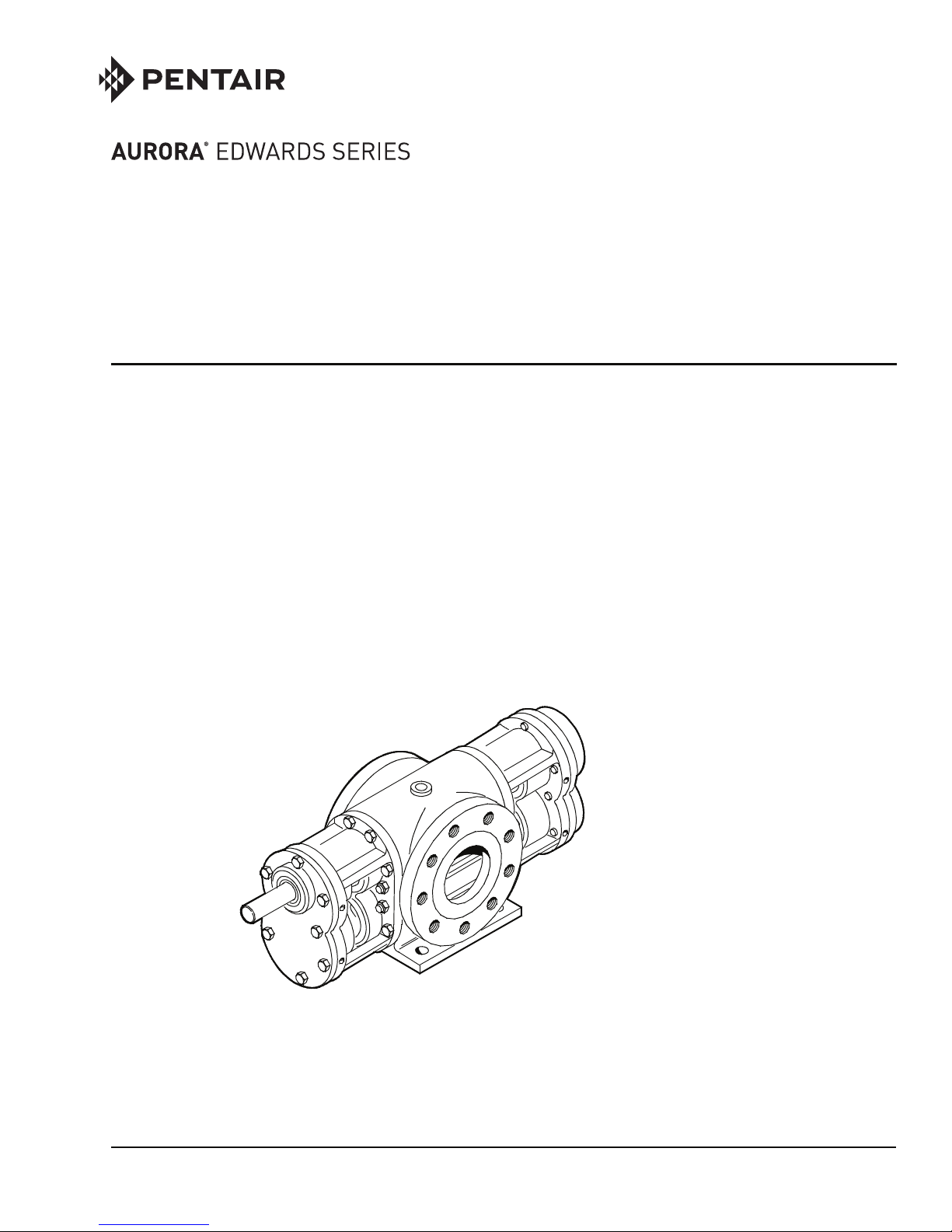
The Edwards Model 400 pump (Figure 1-1) is a standard-duty high-speed gear-driven
positive-displacement rotary pump with gear-type rotors. The pump is self-priming.
Edwards rotary pumps are available in many configurations. While they may look alike,
there may be significant differences from one pump to another. Differences include
construction material, sealing method, rotor type, etc.
General
1
Figure 1-1. Edwards Model 400 Pump
1-1
Maintenance
l
Do not perform maintenance using this manual if the model number on the
pump is not 400-112 or the serial number is not ________________. Performing
maintenance using the wrong manual could result in pump failure or personal
injury.
Edwards rotary pumps are available in many configurations. While they may look alike,
there may be significant differences from one pump to another. Differences include construction material, sealing method, rotor type, etc. This manual covers only one configuration, which is defined by a model number and a serial number. Check the name plate
on the pump to make certain the model number is 400-112 and the serial number is
________________. If the numbers do not match, contact Edwards - Pentair Water.
Most pump repairs can be performed by maintenance personnel using normally available tools.
2
Consumable Materials
Cleaning materials, lubricants, and other products needed during pump maintenance
are listed in Table 2-1.
Table 2-1. Consumable Materials
Item Nomenclature Specification Common Name
1 Lint-Free Cloth MIL-C-85043
2 “Dry” Cleaning Solvent Acetone, Brake
Cleaner
3 Emery Cloth 220 Grit 3M, Anderson,
Sandvik, Mirka
4 Anti-Seize Compound “Nev’r Seize”
5 Red Loctite PermaLoc HH-120
6 High-Tack Gasket Spray Loctite, Permatex
2-1
Model 400 Pump
Table 2-1. Consumable Materials (Continued)
Item Nomenclature Specification Common Name
Zerk fittings do not
have check balls.
This prevents bearings from being
over-greased.
Excess grease will
run out of the fitting when pump is
in operation.
7 General Purpose Grease MIL-G-18709
NLGI #2
Lapping Compound D51804, 180 Grit
8
Silicon Carbide
Chevron Ulti-Plex,
Shell Retina LC
Felpro “Clover”
Brand
Lubrication
To ensure a long service life, the pump should be lubricated routinely with approved
grease (7, Table 2-1). If the pump is operating under normal loads and temperatures,
use the intervals defined in Table 2-2. If the pump is operating at over 180°F, contact
E dwards for recommended lubrication interval for your application.
Table 2-2. Model 400 Lubrication Schedule
Item Interval Amount of Grease
Bearings 1,000 Hours 1.33 Ounce
Timing Gears 1,000 Hours 5.32 Ounce
Troubleshooting
Table 2-3 provides assistance in diagnosing and correcting malfunctions that may occur
during normal operation.
Table 2-3. Troubleshooting
The pump has
heat-treated steel
timing gears,
which can be very
noisy when operated above 900
rpm. This is a normal condition, and
does not require
maintenance
action.
2-2
Trouble Probable Cause Remedial Action
1. Pump does
not turn
2. Excessive
Noise
1a. Seized pump. 1a. Repair or replace pump.
1b. Faulty or misaligned
coupling.
1c. Damaged or missing
shaft key.
2a. Loose or misaligned
coupling.
2b. Cavitation. 2b. Check suction piping with
1b. Replace or realign
coupling.
1c. Replace key.
2a. Tighten, align, or replace
coupling.
a vacuum gauge. Gauge
should read less than 10in. Hg in most cases.
Contact Edwards for the
exact reading for your
application.
Table 2-3. Troubleshooting (Continued)
Trouble Probable Cause Remedial Action
Maintenance
2c. Worn or damaged
bearing(s).
3. Excessive
vibration
4. Reduced flow 4a. Clogged suction screen. 4a. Clean or replace screen.
3a. Loose or misaligned
coupling.
3b. Cavitation. 3b. Check suction piping with
3c. Worn or damaged
bearing(s).
4b. Cavitation. 4b. Check suction piping with
2c. Repair or replace pump.
3a. Tighten,
coupling.
a vacuum gauge. Gauge
should read less than 10in. Hg in most cases.
Contact Edwar ds for the
exact reading for your
application.
3c. Repair or replace pump.
a vacuum gauge. Gauge
should read less than 10in. Hg in most cases.
Contact Edwar ds for the
exact reading for your
application.
align, or replace
4c. Pump liners and/or
rotors worn or damaged.
4d. Low pump speed 4d. Increase pump speed.
4c. Repair or replace pump.
Removal
To avoid injury, always de-energize the input driver and lock-out or red-tag the
controller. Let the pump cool before removing.
1. Before removing pump, refer to troubleshooting chart (Table 2-3) to determine if
the problem is actually the pump.
2. Ensure adequate clearance exists for removal of pump. Disassemble adjacent components as required for adequate working clearance.
3. Before removal, clean exterior parts to remove accumulated dirt, grease, or foreign
material.
4. Apply tags to identify parts of similar configuration to ensure correct installation.
2-3
Model 400 Pump
Disassembly
General Practice
1. Keep work area as clean as possible to avoid contamination of internal parts.
2. Replace gaskets, packings, and seals removed during repair. Replace all keys, spring
washers, and like items during assembly.
3. When removing gaskets, packings, or seals, do not use a metal tool to pry, pick, or
scrape. Doing this could scratch sealing surfaces. Use wood or plastic scrapers to
remove gasket material.
4. Before disassembly of any component, study exploded view illustration (Figure 4-1).
Pay particular attention to relationship of internal parts. Being familiar with construction will speed up disassembly and help avoid improper assembly.
5. To prevent moisture or foreign material from entering open components, install
protective plugs or covers as soon as practical after disassembly. Wrap parts in clean
paper or clean lint-free cloths (1, Table 2-1).
6. Remove only the parts requiring repair or replacement. Do not disassemble pump
any further than necessary to complete needed repairs.
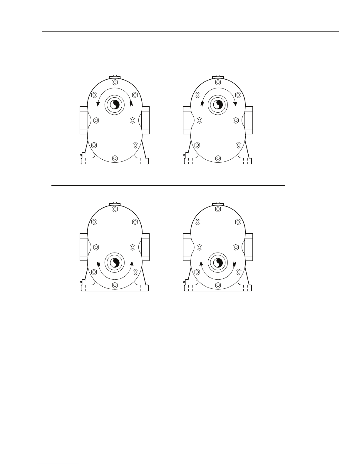
The pump can be
reassembled into
several configurations as shown in
Figure 2-1. Before
disassembling the
pump, circle the
configuration that
matches the pump
being repaired.
This will be an
invaluable aid during reassembly.
When removing the
endcases, use two
pullers, or alternate
one puller between
shafts.
The endcase may be
pulled off each
shaft about 1/8 in.
at a time. Alternate
the puller between
shafts to avoid misalignment during
removal.
Disassembly Procedure
1. Remove cap screws (3, Figure 4-1), timing gear cover (2), and cover gasket (4).
Discard gasket.
2. Loosen timing gear locknuts (8) and unscrew until locknuts reach end of shaft.
This will protect the threads when the timing gears are pulled.
3. Fabricate timing gear puller as shown in Figure 2-2.
4. Install timing gear puller with cap screws on
timing gear (10, Figure 4-1). Tighten screws to take up slack and tap puller with a
hammer in line with shaft to free timing gear. Repeat procedure for other timing
ge ar.
5. Remove locknuts (8) and timing gears (10).
6. Remove cap screws (6), front cover (5), and cover gasket (4). Discard gasket.
7. Remove front cover seal (7) from front cover (5). Discard seal.
8. Remove setscrews (11) from endcases (15).
9. Remove bearing adjusting nuts (12) from endcases (15).
10. Remove cap screws (16), nuts (18), and washers (17) from drive endcase (15).
Do not hammer on pump endcase. This will cause gasket sealing surface damage, resulting in leaks.
Use shaft protector between puller tip and shaft face to prevent distortion of
shaft center.
11. Using gear puller, remove drive endcase (15) and pump body gasket (20). Discard
gasket.
12. Remove cap screws (16), nuts (18), and washers (17) from timing gear endcase (15).
2-4
Maintenance
UPPER DRIVE
DISCHARGE
PORT
SUCTION
PORT
LEFT HAND
ROTATION
SUCTION
PORT
LOWER DRIVE
DISCHARGE
PORT
RIGHT HAND
ROTATION
DISCHARGE
PORT
SUCTION
PORT
LEFT HAND
ROTATION
NOTE: ALL ROTATIONS ARE VIEWED FROM PUMP SHAFT END.
Edwards USES THE FOLLOWING NOTATION FOR PUMP IDENTIFICATION:
RIGHT HAND
ROTATION
UR = UPPER SHAFT – RIGHT HAND ROTATION
UL = UPPER SHAFT – LEFT HAND ROTATION
LR = LOWER SHAFT – RIGHT HAND ROTATION
LL = LOWER SHAFT – LEFT HAND ROTATION
Figure 2-1. Pump Configuration Diagram
1070_0002a.cdr
2-5
 Loading...