

Page 1
SMART UV®
UV DISINFECTION STERILIZER
IMPORTANT SAFETY INSTRUCTIONS
READ AND FOLLOW ALL INSTRUCTIONS
SAVE THESE INSTRUCTIONS
INSTALLATION AND
USER'S GUIDE
Page 2

2
CUSTOMER SERVICE / TECHNICAL SUPPORT
If you have questions about ordering Pentair replacement parts and products, please contact:
CUSTOMER SERVICE AND TECHNICAL SUPPORT, USA
Monday to Thursday: 8 AM to 6:30 PM EST
Friday: 8 AM to 5 PM EST
Phone: (877) 347-4788
Fax: (407) 886-6787
INTERNATIONAL
Phone: (407) 866-3939
Fax: (407) 866-4884
WEB SITE
Visit www.PentairAES.com for information about Pentair products.
©2018 Pentair Aquatic Eco-Systems, Inc. All rights reserved.
This document is subject to change without notice.
2395 Apopka Blvd., Apopka, FL 32703, USA
Phone: 407.886.3939 Web: PentairAES.com
All Pentair trademarks and logos are owned by Pentair or one of its global afliates. Pentair Aquatic Eco-Systems® and
SMART UV Systems™ are trademarks and/or registered trademarks of Pentair Aquatic Eco-Systems, Inc. and/or its
afliated companies in the United States and/or other countries. Unless expressly noted, names and brands of third
parties that may be used in this document are not used to indicate an afliation or endorsement between the owners
of these names and brands and Pentair Aquatic Eco-Systems, Inc. Those names and brands may be the trademarks or
registered trademarks of those third parties. Because we are continuously improving our products and services, Pentair
reserves the right to change specications without prior notice. Pentair is an equal opportunity employer.
P/N 02934-INS-SMART REV. D 8/18
SMART UV® U V DISINF ECTION STERILIZER Ins tallation and User 's Guide
Page 3

TABLE OF CONTENTS
3
Important Warning and Safety Instructions .......... 4
Warranty Information ...............................................5
System Features and Specications ...................... 6
SMART UV® Features ..........................................6
System Specications ......................................... 6
Sizing Chart.......................................................... 6
Pre-Installation Inspection ..................................... 7
Component Diagram ........................................... 7
Power Supplies .................................................... 7
Quartz Sleeve and UV Lamp Inspection ............ 8
Installation ................................................................. 9
Quartz Sleeve Assembly and Installation ..........9
Sterilizer Installation and Operation ................. 10
Typical Installation ...................................... 10
Mounting the Vessel .................................... 10
Mounting the Power Supply ....................... 11
Mandatory Leak Test ......................................... 11
Electrical Connection ........................................ 12
UV Lamp Installation ......................................... 12
Lamp Styles ................................................. 12
Power Cord Adjustment .............................. 12
SMART UV Installation and Operation ............. 14
Pond Installation Congurations ................ 14
Aquarium Installation Congurations ........ 14
Maintenance ........................................................... 16
Quartz Sleeve Cleaning ..................................... 16
Winterizing ......................................................... 16
Lamp Connector Removal ................................ 17
Troubleshooting ...................................................... 18
Replacements Parts ............................................... 19
SMART UV ......................................................... 19
SMART HO UV ................................................... 20
SMART UV® U V DISINF ECTION STERILIZER Ins tallation and User 's Guide
Page 4
4
IMPORTANT SAFETY INSTRUCTIONS
IMPORTANT NOTICE
This guide provides installation and operation instructions for the
SMART UV® Sterilizer. Consult Pentair with any questions regarding
this equipment.
Attention Installer: This guide contains important information
about the installation, operation and safe use of this product. This
information should be given to the owner and/or operator of this
equipment after installation or left on or near the UV system.
Attention User: This manual contains important information that will
help you in operating and maintaining this product. Please retain it for
future reference.
IMPORTANT SAFETY INSTRUCTIONS! PLEASE READ PRIOR
TO INSTALLATION AND OPERATION!
Strictly follow the instructions within this manual to ensure the health
and safety of both, yourself and the UV system. The installation,
operation and maintenance of the UV system can only be carried out
after reading and understanding the information contained in this
manual.
The installation of the UV system must be carried out in accordance
with local regulations and codes.
READ AND FOLLOW ALL INSTRUCTIONS
This is the safety alert symbol. When you see this symbol on
your system or in this manual, look for one of the following signal
words and be alert to the potential for personal injury.
Warns about hazards that can cause death,
serious personal injury, or major property
damage if ignored.
Warns about hazards that may cause death,
serious personal injury, or major property
damage if ignored.
Warns about hazards that may or can cause
minor personal injury or property damage if
ignored.
NOTE Indicates special instructions not related to
hazards.
Carefully read and follow all safety instructions in this manual and
on equipment. Keep safety labels in good condition; replace if
missing or damaged.
When installing and using this electrical equipment, basic
safety precautions should always be followed, include the
following:
FAILURE TO FOLLOW ALL INSTRUCTIONS AND
WARNINGS CAN RESULT IN SERIOUS BODILY INJURY OR
DE AT H .
INSTALLERS, OPERATORS AND OWNERS MUST READ THESE
WARNINGS AND ALL INSTRUCTIONS IN THE OWNER’S
MANUAL BEFORE USING THIS PRODUCT. THESE WARNINGS
AND THE OWNER’S MANUAL MUST BE LEFT WITH THE
OWNER.
Ultraviolet light is damaging to your eyes and skin ! DO
NOT handle or stare at an operating UV lamp. Note that the UV light
rays are invisible to the human eye and precautions should be taken
to prevent UV energy from entering the eyes.
ULTRAVIOLET RADIATION. Disconnect all power
from the unit before replacing lamps or servicing the unit.
The quartz sleeve and or the UV lamp shipped with
this product may have been broken or damaged during transit. It
is therefore essential that the unit be carefully inspected before
connecting to electric al power.
To prevent possible fire or electrical shock, only use
replacement lamps specified by the manufacturer.
DO NOT allow system to exceed 50 PSI (Pounds Per
Square Inch ).
DO NOT operate this unit above rated flow rate.
Operating the product in this manner may result in product failure
and voiding of warranty.
To avoid possible electrical sho ck, special care should
be taken since water is employed in intended applications. For each
of the following situation, DO NOT attempt repairs yourself. Call
Pentair customer service depar tment at 877-347-4788 for services or
discard the appliance.
If unit falls into the water, DO NOT REACH FOR IT!
First power down the unit and then retrieve it. If the internal electrical
components of the unit get wet, keep the unit powered down until
internal electrical com ponents have dried.
If the unit shows any sign of water leakage, immediately
power down the unit.
Carefully examine the unit after installation. It should
not be powered on if there is water on any part not intended to be wet.
SMART UV® U V DISINF ECTION STERILIZER Ins tallation and User 's Guide
Page 5
IMPORTANT SAFETY INSTRUCTIONS
5
To reduce the risk of injury, DO NOT permit children to
use this produ ct.
SMART UV® systems are designed for low-pressure
water applications DO NOT use these units for any application outside
of their intended use. The use of attachments not recommended or
sold by the original manufacturer may cause unsafe conditions and
may voi d a ny warr anty.
This unit must be wired in conjunction with a
properly grounded, Ground Fault Circuit
Interrupter (GFCI) . Only three (3) wire grounded cables suitable for
outdoor use should be used to connect this unit. If joining cables for
outdoor use, a suitable watertight cable connector must be used. If
an extension cord is necessary, a cord with a proper rating should
be used. A cord rated for less amperes or watts than the appliance’s
rating may overheat. Care should be taken to arrange the cord so
that it will not be tripped over or pulled. If in doubt consult a qualified
electrician.
WARRANTY INFORMATION
Warping of the UV body may occur when left in direct
sunlight without water inside to help dissipate the heat.
DO NOT operate the unit in “no-flow ” situations.
SAVE THESE INSTRUCTIONS
PENTAIR warrants to the original purchaser, the SMART UV
Ultraviolet Sterilizers to be free from defects in workmanship or
materials for a period of 1 year from the date purchase on power
supply and all gaskets seals.
The UV vessel has a 3-year warranty if failure is caused from the UV
lamp light exposure. Warranty will be void if water leaks are caused by
failing to follow the proper assembly instructi ons.
The UV lamp has a 90 -day warranty on the electrical operation only.
The warranty is only in effect provided the equipment is installed
in accordance with the factory instructions, recommendation and
operated within the environment and limitations for which it was
designed.
SMART UV® U V DISINF ECTION STERILIZER Ins tallation and User 's Guide
Page 6

6
SYSTEM FEATURES AND SPECIFICATIONS
All SMART UV® Systems UV Sterilizer models are
packaged complete, with all necessary components
that are required to operate the unit. When unpacking,
it is recommended to perform a complete component
inventory to ensure everything is accounted for and
hasn't been damaged.
The serial number of your UV unit is located on a
small white label near the electrical end of the unit’s
vessel.
The model number of your UV unit can be found in
two locations:
1. On the bar code label at the end of the box.
2. On the label placed in the middle of the UV Vessel,
with a hole punch indicating the model number.
SMART UV Features
Our GPH T-5 and T-6 low pressure mercury vapor
germicidal amps, convert approximately 30% of their
electrical input watts into UV-C output watts within
the germicidal action spectrum (meaning 30% of
electricity used is converted into useful germicidal
UV light), the highest UV-C output conversion among
all UV lamps.
• UL listed for indoor and outdoor use, fresh and salt
water use.
• Long lasting GPH/T5 and GPH/T6 UV lamps (9,000
hours to 80% efciency).
• Protective Quartz Sleeve (maximizes UV lamp
output and safety)
• Watertight Design
• Easy-to-Remove Power Assembly
• Remote Power Supply
• UV Resistant High Density Plastic UV Vessel
• Utilizes the UV lamp to its maximum potential
(maximum UV exposure)
• Non-UV Transmitting Clear Lamp Viewing Ports
System Specications
Max Flow
Model
No.
EU18-U 6 GPM 18 0.34-0.17 5.4 23” X 4” 120-240 VAC
EU25-U 9.5 GPM 25 0.40-0.20 7.5 29” X 4” 120-240 VAC
EU40 15.5 GPM 40 0.44-0.22 12 44” X 4” 120-240 VAC
EU65P 26 GPM 65 0.46-0.23 19.5 71” X 4” 120-240 VAC
E50S 26 GPM 50 1.15/0.57 15 28" x 5.75" 120-240 VAC
E80S 45 GPM 80 1.15/0.57 26 43" x 5.75" 120-240 VAC
E120S 64 GPM 120 1.15/0.57 36 56" x 5.75" 120-240 VAC
E150S 100 GPM 150 1.82 47 70" x 5.75" 120 VAC
E150S-2 100 GPM 150 0.81 47 70" x 5.75" 240 VAC
Rate @ 30
mJ/cm2
Lamp
Wattage
Amperes
(A)
UV-C
Output
Watts
Dimensions
H x W
(Inches)
Input Voltage
(50/60 Hz)
Port
Connection
1.5” Union/
1” Barb
2” Union
SMART UV® U V DISINF ECTION STERILIZER Ins tallation and User 's Guide
Page 7
PRE-INSTALLATION INSPECTION
7
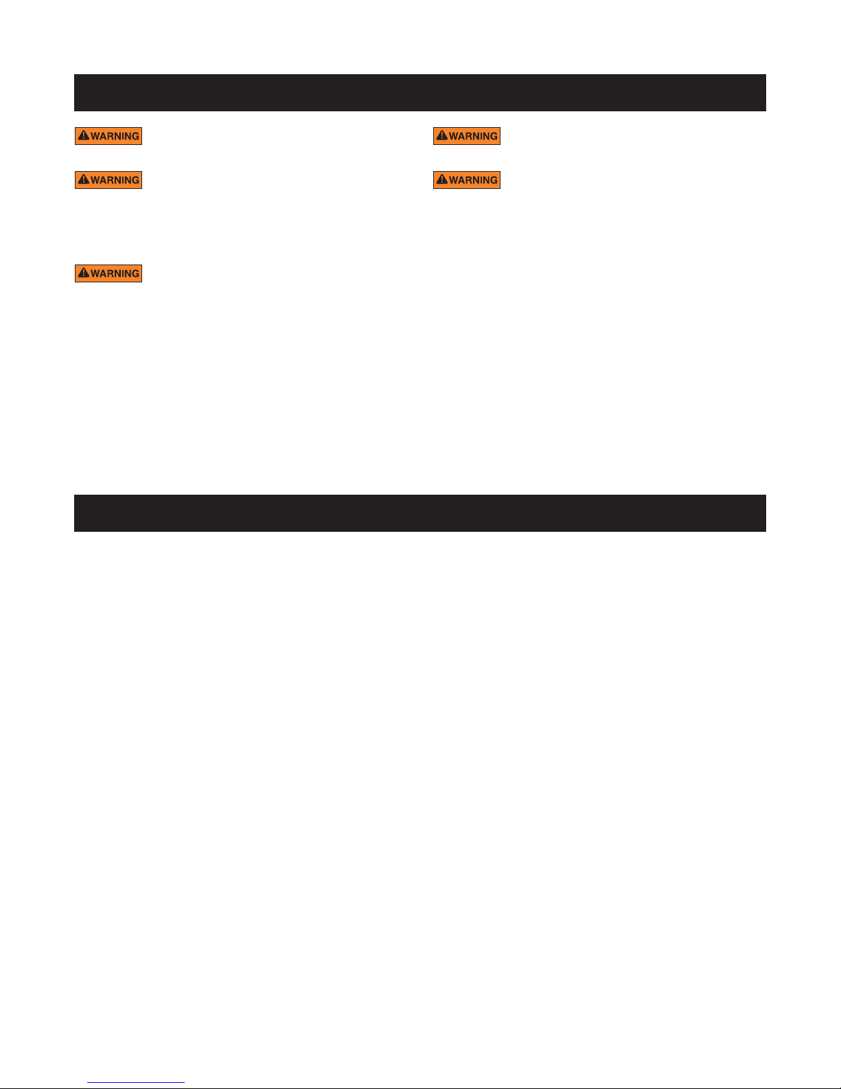
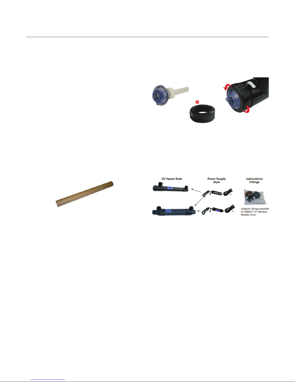
Component Diagram
Please review the component diagram below.
Unpack your UV system, and lay out the packaged
components for inspection. Please review the
information listed in this section to become familiar
with the equipment’s various parts.
SMART UV® Sterilizer Models:
Part Numbers EU18-U, EU25-U, EU40 & EU65P
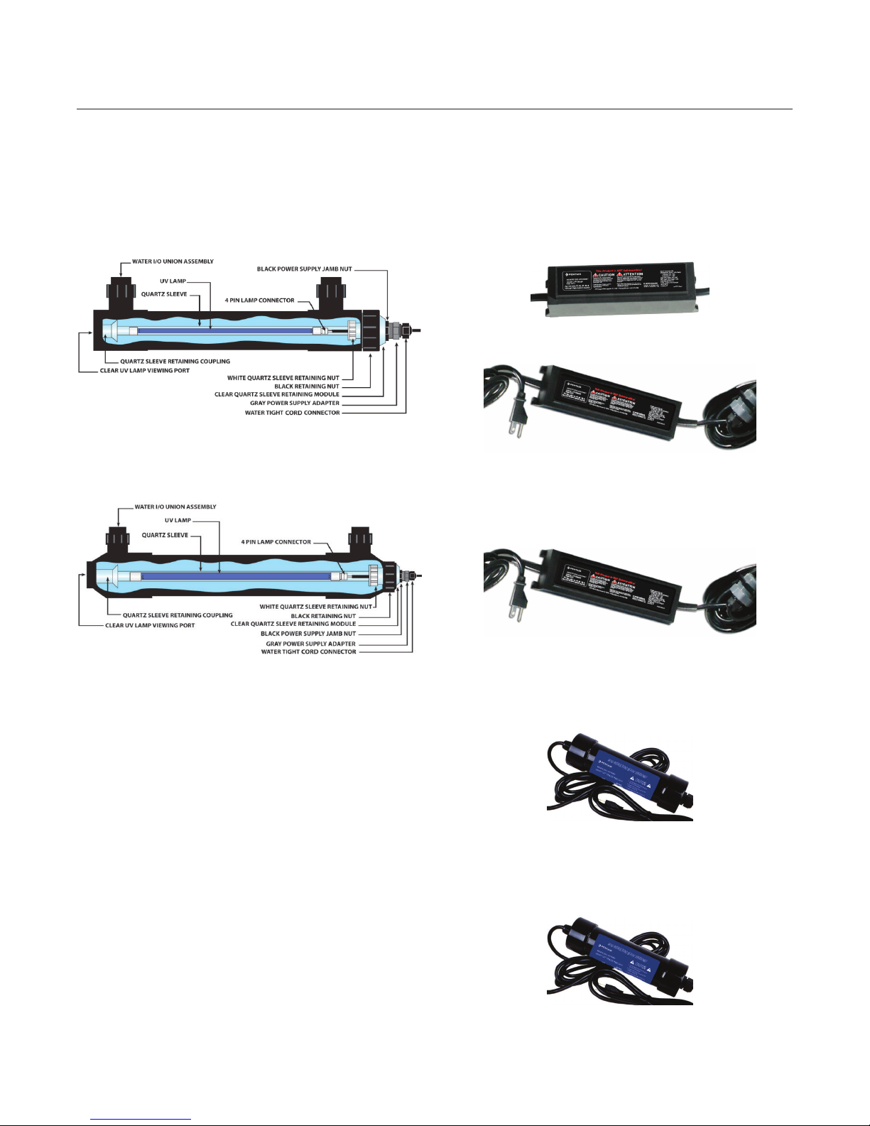
Power Supplies
The power supply can either be a cylinder “POD”
or a rectangle style. Below are the ballasts that are
currently used with the SMART UV line.
For SMART Lite and SMART
18W, 25W, 40W, and 65Watt Units.
20120-MV – 120VAC/240VAC 50/60 Hz
20100 – 120VAC 50/60 Hz
For SMART HO 50W, 80W, and 120Watt Units.
SMART UV HO Sterilizer Models:
Part Numbers E50S, E80S, E120S & E150S
20105-MV – 120VAC/240VAC 50/60 Hz
For SMART HO 150W (120VAC)
202150-1 – 120VAC 50/60 Hz
For SMART HO 150W (240VAC)
202150-2 – 240VAC 50/60 Hz
SMART UV® U V DISINF ECTION STERILIZER Ins tallation and User 's Guide
Page 8
8
PRE-INSTALLATION INSPECTION
Quartz Sleeve and UV Lamp Inspection –
When Packed in Tube
SMART UV® Disinfection Sterilizers are packaged
with their quartz sleeve assembly pre-assembled
inside the UV vessel.
The UV lamp is packaged separately in a corrugated
tube.
The Quartz Sleeve Assembly must be removed from
the UV vessel and inspected for damage prior to
installation. Extreme care should be used while this
procedure is being performed.
Note: DO NOT handle the lamp or quartz sleeve with
bare hands. Your hands can deposit oils on the quartz
sleeve and lamp that will decrease the efciency of
UV disinfection.
1. Carefully unpack the UV lamp from their corrugated
packing tube and inspect for damage including
broken glass, cracks, chips, fractures and pin
holes. If damage has occurred please contact the
place of original purchase immediately.
2. Carefully, remove the quartz sleeve by unthreading
the Black Retaining Nut. Gently slide out the
quartz sleeve assembly and inspect for damage
including chips, cracks and pin holes. If damage
has occurred please contact the place of original
purchase immediately.
3. After inspection, reassemble the quartz sleeve
back into the UV vessel. Perform the Mandatory
Leak Test (see page 7).
4. Inspect all other UV system components (power
supply, UV vessel unions and necessary mounting
clamps) for damage.
NOTE: Save the corrugated lamp packaging after
unpacking the UV lamp. Storing the lamp and/or
quartz sleeve in this packaging while performing
maintenance on the UV system will protect these
components from damage or fouling when outside of
the vessel.
After receipt and inspection of the unit, if broken
glass is found (including cracks, chips, pin holes
and hair line fractures of any kind) please contact
the place of original purchase immediately for
replacements.
SMART UV® U V DISINF ECTION STERILIZER Ins tallation and User 's Guide
Page 9

INSTALLATION
9
Improper assembly may result in water
damage to electrical components and unsafe
conditions. The manufacturer is not responsible for
damage cause by improper re-assembly of these
parts.
Quartz Sleeve Assembly Includes:
1. Quartz Sleeve
2. White Quartz Sleeve Retaining Nut
3. Rubber Gasket
4. Clear Quartz Sleeve Module
5. Clear Quartz Sleeve Module O-ring
6. Power Supply Gasket
5. With the quartz sleeve positioned inside the
clear quartz sleeve module properly, nish handtightening the white retaining nut. When the white
retaining nut is tight, the quartz sleeve should
appear straight inside the clear quartz sleeve
module (see Photo B).
NOTE: If the quartz sleeve appears crooked it may
leak. Disassemble and try again.
6. Carefully slide the quartz sleeve assembly into
the UV vessel (see Photo D). The domed-end of
the quartz sleeve should slide into the coupling
located on the non-electrical end of the UV vessel
(see Photo C).
Assembly Instructions
1. Position the white quartz sleeve retaining nut and
rubber gasket over the open end of the quartz
sleeve.
3. Slide the “open-end” of the quartz sleeve (with nut
and gasket in position) into the clear quartz sleeve
module.
3. Thread the white retaining nut onto the clear quartz
sleeve module’s male threads and hand-tighten.
4. While hand-tightening the white retaining nut onto
the clear quartz sleeve module, use your index
nger to ensure that the open-end of the quartz
sleeve mates smoothly with the inside lip of the
clear quartz sleeve module; this signies a good
t. See Photo A.
7. With the quartz sleeve assembly properly in place,
the quartz sleeve retaining module should sit ush
against the top of the UV vessel. See Photo E.
NOTE: Be sure that the clear quartz sleeve module
O-ring and gasket is properly seated in the bottom
of the quartz sleeve module (see item #6 on page 4).
SMART UV® U V DISINF ECTION STERILIZER Ins tallation and User 's Guide
Page 10

10
INSTALLATION
8. Thread the black retaining nut (see Photo F) onto
the male threads of the UV vessel. Hand tight only!
9. Using the instructions given on page 7, perform the
Mandatory Leak Test. If no leaks are found proceed
to page 8, UV Lamp Installation, for instructions on
installing the UV lamp.
Sterilizer Installation and Operation
DO NOT operate the UV system at ow
rates higher than 90 GPM (341 LPM). Operating the
product in this manner may result in product failure
and voiding of warranty.
SMART UV® Disinfection Sterilizers are used in
a variety of applications to control waterborne
pathogens. Pentair encourages the consideration of
the installation recommendations provided here.
Suspended solid debris will absorb UV light and
reduce the UV transmittance through water. By
operating the SMART UV system after the mechanical
lter, the unit's overall performance will be increased.
Vertical Vessel Mounting
Mount the SMART UV Disinfection
Sterilizer with the electrical end up.
Use the bottom port as the inlet
with the top port as the outlet.
Note: The UV vessel should be
installed with a vertical clearance
1½ times the vessel length. This will
allow sufcient room for servicing
the unit and replacing the UV lamp
The inlet and outlet
plumbing MUST be supported to
avoid vessel material stress.
Failure to support the inlet and outlet plumbing may
lead to damage to the vessel.
Horizontal Vessel Mounting
Mount the SMART UV system horizontally with the
inlet/outlet facing up. If the unit is mounted but
not level, the electrical end of the unit should be
positioned higher than the non-electrical end. Choose
the lower port of the inlet
NOTE: The UV vessel should be installed with a
horizontal clearance 1½ times the vessel length. This
will allow sufcient room for servicing the unit and
replacing the UV lamp.
The efciency of the UV sterilizer operation is directly
related to the recommended water ow rates found
in the “Sizing Chart”, on page 1.
Mounting the Vessel
Note: The way UV vessels are mounted/positioned
plays a very important role in the unit’s performance
and degree of safety. We STRONGLY RECOMMEND
that you follow these instructions and guidelines
precisely. Any deviation from these mounting
instructions will void any warranty associated with
the UV vessel and all its components and may cause
unsafe conditions.
Trapped air inside the UV vessel during
operation may create excessive heat thus damaging
internal components.
SMART UV® U V DISINF ECTION STERILIZER Ins tallation and User 's Guide
Page 11

INSTALLATION
11
Mounting the Power Supply
Depending on the style of power supply cylinder or
rectangle the SMART UV® system’s power supply can
be mounted two ways, mounting tabs at the corner
of the ballast or using the mounting clamps for the
cylinder type of ballast. The power supply should
always be mounted to a surface that is sheltered from
rain, splashing, heavy condensation or any other kind
of prolonged contact with water.
NOTE: DO NOT mount the power supply in an
extremely conned space where heat and moisture
can be retained.
Your UV system will include one of two different
power supplies based on the wattage of your unit:
• 50W, 80W and 120W UV systems include a
rectangular power supply. Four screws, one in
each corner of the power supply, secure the power
supply to the wall or shelf.
IMPORTANT NOTE: Failure to perform a leak test
could lead to conditions that will void your product
warranty.
To Perform Mandatory Leak Test:
1. Prepare the UV system for permanent operation
by plumbing it in-line, into a lter system using the
plumbing hardware of your choice. If PVC glue is
used, follow the glue manufacturer’s instructions.
2. If UV lamp is installed, with the unit plumbed for
operation and the clear quartz sleeve module
securely in place, remove the UV lamp from the
quartz sleeve module.
3. Roll-up a few paper towels creating a core
3
approximately
then slide into the open quartz sleeve module port.
Insert about 6-inches of the paper towel core down
into the quartz sleeve, as shown.
/
4 inch diameter, 10-inches long
• 150W UV systems include a cylindrical power
supply that must be mounted with the two pipe
clips packaged with the unit.
A single screw at the base of the pipe clip secures it
to the wall or shelf. The power supply is then locked
into the pipe clip by securing the retaining strap onto
the clip.
Mandatory Leak Test
A leak test should be performed each time the quartz
sleeve is installed inside the unit’s vessel or when the
quartz sleeve or gaskets are replaced [Once annually].
Performing a leak test is a precautionary measure
that will determine whether or not the critical seal
between the quartz sleeve and quartz sleeve module
has been achieved.
Failure to achieve a proper quartz sleeve/quartz
sleeve module seal during SMART UV Disinfection
Sterilizer operation will allow water to leak into the
inside of the quartz sleeve, potentially damaging the
UV lamp and other electrical components, which
could develop into dangerous situations.
4. With the paper towel in place, turn on the pump
and recirculate water through the UV vessel for at
least thirty (30) minutes.
5. After thirty (30) minutes of recirculating water
through the UV vessel, remove the paper towels
from the quartz sleeve module. Inspect closely for
moisture. If the paper towel is completely dry, your
leak test is complete and successful.
If moisture is detected on the paper towel the quartz
sleeve’s rubber gasket and O-ring have failed to
achieve a seal and must be re-assembled; repeat
the leak test until a seal is achieved. See page 4 for
assembly instructions.
SMART UV® U V DISINF ECTION STERILIZER Ins tallation and User 's Guide
Page 12

12
INSTALLATION
Electrical Requirements
The electrical requirements for the UV sterilizer are
marked on the unit’s power supply label (Ex. 120VAC
50/60Hz.). The unit must be plugged into a wellgrounded electrical outlet.
Do not attempt to cut the ground post
off of the 3-prong plug, doing so will void the unit’s
warranty.
This product must be grounded. If the unit should
fail electrically, grounding provides a path of least
resistance for electric current to pass to reduce
the risk of electric shock. This product’s cord is
equipped with an equipment-grounding conductor
and a grounding plug. The plug must be plugged
into an appropriate outlet that is properly installed
and grounded in accordance with all local codes and
ordinances. If in doubt consult a qualied electrician.
DO NOT operate this equipment with
timing devices.
Improper connection of the equipmentgrounding conductor can result in a risk of
electrocution. Check with a qualied electrician or
service personnel if unsure that the outlet is properly
grounded. Do not product’s plug. If it will not t into
the electrical outlet, have a proper outlet installed by
a qualied electrician. Type of plug adapter with this
product.
within the GFCI outlet generates a trip signal which is
applied to a coil that trips the main (normally closed)
contacts. These contacts open and break the circuit.
Ghost Trips
Consider that all GFCI’s must trip at a leakage current
of 5 ma. GFCI “Ghost Trips” are caused by electrical
devices that have small electrical leakage current to
ground. Multiple outlets protected by one GFCI allow
for potential cumulative leakage currents caused by
multiple appliances each leaking small amounts of
current.
Example: One pump plugged into an outlet that is
part of a four outlet branch protected by one GFCI
will not trip the GFCI with its 2 mA leakage current.
However, two pumps and a UV with a cumulative
leakage current of 7 mA will trip the GFCI. This is a
common problem.
The solution to the GFCI “Ghost Trip” problem is to
operate the device on its own GFCI protected outlet,
or, remove other devices from the GFCI protected
branch of outlets. If the GFCI is over ten years old,
you may want to consider replacing it.
UV Lamp Installation
Lamp Styles
UV lamps are manufactured with color coded ceramic
bases. White-capped UV lamps signify a StandardOutput UV lamp while red-capped UV lamps signify a
High-Output UV lamp.
Power Cord Adjustment
Ground Fault Circuit Interrupter
(GFCI) Protection
This unit must be wired in conjunction
with a properly grounded, Ground Fault Circuit
Interrupter (GFCI). Only three (3) wire grounded
cables suitable for outdoor use should be used to
connect this unit. If joining cables for outdoor use, a
suitable watertight cable connector must be used. If
an extension cord is necessary, a cord with a proper
rating should be used. A cord rated for fewer amperes
or watts than the appliance’s rating may overheat.
Care should be taken to arrange the cord so that it
will not be tripped over or pulled. If in doubt consult a
qualied electrician.
GFCI’s are designed to sense an imbalance in
electrical current ow within the main electrical leads
(leakage current). When this imbalance (maximum 5
mA per UL) occurs in the main leads, a comparator
SMART UV® U V DISINF ECTION STERILIZER Ins tallation and User 's Guide
There should be 4-inches of cord between the Gray
Adapter (3) and the 4-pin Lamp Connector (1). The
4-inch cord distance positions the lamp properly
inside the quartz sleeve.
1. The
(1) is adjustable. Loosen it gently move the cord
through it. Care must be taken when retightening.
If the Connector’s Rubber Gasket Seal is dislodged
during cord adjustment please make sure that it
is properly re-seated inside the male threaded
portion of the connector.
4 Inches between Gray Adapter (3) and 4-Pin Connector (4)
3
/
8 inch Threaded Watertight Cord Connector
Page 13

INSTALLATION
2. After a successful leak test and without the power
supply connected to a control box, attach the
lamp’s 4-pins to the power cord’s white 4-pin
Connector (4), then slide the UV lamp back into the
quartz sleeve.
13
3
NOTE: By loosening the
Cord Connector (5), Power Cord adjustments can be
made. Make sure the
Cord Connector’s gasket is properly in place before
retightening.
/
8 inch Threaded Watertight
3
/
8 inch Threaded Watertight
3. Whether the SMART UV® Disinfection Sterilizer
vessel is mounted horizontally or vertically, care
should be taken when installing the UV lamp into
the vessel’s quartz sleeve. Vertical installations
require extra attention to eliminate the chance
of the lamp dropping into the quartz sleeve and
breaking.
4. With the UV lamp/power cord connection complete
and the lamp entirely inside the quartz sleeve,
carefully screw down the Gray Power Supply
Adapter (3) onto the Clear Quartz Sleeve Module
(6); hand tighten only.
5. Screw down the Black Power Supply Jamb Nut (4)
until it makes contact with the Clear Quartz Sleeve
Module (6).
NOTE: If you do not have the Black Power Supply
Jamb Nut (4) back far enough before tightening the
Gray Power Supply Adapter (3), the gray adapter
will not make contact with the power supply gasket
and will enable outside moisture to enter the quartz
sleeve assembly and cause a system failure.
SMART UV® U V DISINF ECTION STERILIZER Ins tallation and User 's Guide
Page 14

14
OP ERATI ON
SMART UV® Installation and Operation
SMART UV Systems UV Sterilizers are used in
a variety of applications to control waterborne
pathogens. Pentair encourages the consideration of
the installation/operation recommendations provided
here.
Suspended solid waste will absorb UV light and
reduce the UV transmittance through water. By
operating the SMART UV after the mechanical lter,
the unit’s overall performance will be increased.
When operating SMART UV sterilizers please
consider the recommended water ow rates.
Pond Installation Congurations
Small to Moderately Sized Ponds (up to 5,000
Gallons) Using Skimmers and Falls
Placing the UV between the skimmer box and the
lter ensures that pre-ltered water reaches the
UV, increasing its performance while reducing
maintenance.
Often the capacity of the pump exceeds the capacity
of the UV. If this is the case, install a bypass manifold.
Be sure that the skimmer is equipped with mechanical
ltering capacity. See Diagram 1.
Larger Sized Ponds (above 5,000 Gallons) Using
Surface Skimmer and Pressurized Filter
This system is simple yet it achieves critical ltering
goals, such as good water circulation for increased
solid waste suspension. The bottom drain/surface
skimming capabilities ensure maximum waste
removal. See Diagram 2.
The SMART UV System UV Sterilizer is positioned
after the mechanical lter where it can receive only
solid waste free water, optimizing UV transmittance/
performance. Notice the 3-way valve that regulates
suction from the skimmer and drain to the pump,
allowing ow control.
NOTE: Before gluing piping or reducer bushing into
the UV’s union or socket, remove the quartz sleeve
assembly to prevent glue from dripping onto the
quartz sleeve.
NOTE: Use threaded seal tape on all threaded
connections.
Next, multiple “clean water returns” improve
circulation, suspending solid waste and helping it to
nd the lter. If you have a ow rate that exceeds the
UV’s, install a by-pass manifold. See Diagram 1.
NOTE: Before gluing piping or reducer bushing into
the UV’s union or socket, remove the quartz sleeve
assembly to prevent glue from dripping onto the
quartz sleeve.
NOTE: Use threaded seal tape on all threaded
connections.
Aquarium Installation Congurations
Canister Filter/Aquarium Installation
Pressurized Canister lters are commonly used with
small freshwater/saltwater aquariums. Diagram 3
shows a SMART UV model.
It is important to match the Canister Filter’s ow rate
to the capacity of the SMART UV. If this is not feasible,
use a bypass manifold (see Diagram 5 on page
14). To prevent back-siphoning, consider installing
SMART UV® U V DISINF ECTION STERILIZER Ins tallation and User 's Guide
Page 15

OP ERATI ON
15
a check valve or ball valve (see lter instructions/
recommendations). See Diagram 3.
ow adjustments and UV removal. For best results,
install a saddle-style water ow meter, mounted
horizontally on the outlet side of the UV. Follow the
water ow meter manufacturer’s instructions for
proper installation and operation. See Diagram 4.
NOTE: Before gluing piping or reducer bushing into
the UV’s union or socket, remove the quartz sleeve
assembly to prevent glue from dripping onto the
quartz sleeve.
NOTE: Before gluing piping or reducer bushing into
the UV’s union or socket, remove the quartz sleeve
assembly to prevent glue from dripping onto the
quartz sleeve.
NOTE: Use threaded seal tape on all threaded
connections.
Wet-Dry with External or Submersible Pump
Installation
This installation conguration shows the SMART
UV System® UV Sterilizer capacity matched to the
recirculating ow rate performance of the pump.
We recommend mechanical lter media being used
inside the over-ow and at the top of the wet-dry
lter.
Installing a check valve after the UV will eliminate back
siphoning. Installing true-union ball valves will allow
NOTE: Use threaded seal tape on all threaded
connections.
Wet-Dry w/External or Submersible Pump
Installation
This installation conguration is identical to Diagram
4 with the addition of a bypass manifold. The bypass
is used to deliver a precise water ow to the SMART
UV when the overall clean water return ow rate
exceeds the UV’s capacity.
Installing a check valve after the UV will eliminate
back siphoning. Installing true union ball valves will
allow ow adjustments and easy UV removal for
servicing. For best results, install a saddle-style water
ow meter, mounted horizontally on the outlet side of
the UV. Follow the water ow meter manufacturer’s
instructions.
NOTE: Before gluing piping or reducer bushing into
the UV’s union or socket, remove the quartz sleeve
assembly to prevent glue from dripping onto the
quartz sleeve.
NOTE: Use threaded seal tape on all threaded
connections
SMART UV® U V DISINF ECTION STERILIZER Ins tallation and User 's Guide
Page 16

16
MAINTENANCE
Quartz Sleeve Cleaning
It is recommended that the quartz sleeve be visually
inspected for cleaning once every six months of
operation. Even the slightest layer of material (slim/
dirt) coating the outside of the quartz sleeve can
have a substantial effect on UV-C light transmittance
through the glass and into the water.
Cleaning frequency is also dependent on how well
water is being ltered before reaching the SMART
UV® Systems UV Sterilizer. Water that contains solid
waste will deposit greater amounts of material onto
the quartz sleeve and will increase the frequency of
necessary cleaning.
To Clean the Quartz Sleeve (for above water-level
installations only):
1. Disconnect power to the UV sterilizer and pool
pump at the circuit breaker.
2. Relieve any residual pressure that may remain in
the system.
3. Unthread the Black Retaining Nut and gently
remove the Quartz Sleeve Assembly and lamp
from the UV vessel.
Winterizing
Using the SMART UV Disinfection Sterilizer in
extremely cold temperatures can cause damage to
the unit, especially if the water is allowed to freeze
inside the equipment. Please note that damage to
the product due to freezing is not covered under
warranty.
Pentair recommends shutting the UV system down
when the temperature consistently falls below 40°F
(4°C).
1. Drain all water from the UV system.
2. Disassemble the entire unit and carefully clean
both the outside and interior of the UV body and
components.
3. Once clean and dry, store the UV vessel and power
supply in a dry place for the winter.
4. Return the UV system to service when temperatures
consistently return to 40°F (4°C) or greater.
NOTE: Be sure to replace the quartz sleeve gasket and
perform a leak test prior to operating the equipment.
4. Inspect the Quartz Sleeve and clean as needed
with a soft, clean cloth.
5. If calcium deposits are present use vinegar or
a mixture of water and muriatic acid to dissolve
the deposits. If using muriatic acid a ratio of four
parts water to one part acid should sufce. Always
introduce acid to the water and never introduce
the water to the acid.
Muriatic acid is corrosive and can lead
to inammation or burns to body tissue.
ALWAYS wear rubber gloves, safety
glasses and an N-95 dust mask when
handling acid to prevent serious bodily
injury.
To prevent degradation of the acid by UV
light, store muriatic acid in an opaque
container and away from direct sunlight.
6. Remove ALL vinegar or acid from the quartz sleeve
assembly before reassembling.
SMART UV® U V DISINF ECTION STERILIZER Ins tallation and User 's Guide
Page 17

MAINTENANCE
17
Lamp Connector Removal
In the event that you would need to replace you
4-pin lamp connector, follow these steps:
1. Unplug the UV sterilizer and disconnect power to
the water pump at the circuit breaker.
2. Remove UV lamp from the quartz sleeve.
3. Unplug the UV lamp from the connector/power
cord.
4. Grasp the white 4-pin lamp connector with a pair of
pliers while standing on the power cord itself.
5. Pull hard, while twisting slightly. The connector will
disconnect.
6. Check to be sure the ends of the electrical wires
are still tinned; they are pre-soldered before they’re
pushed into the connector. If they are no longer
tinned, you will need to dip them in ux and then
solder to make them rm enough to push back in
the new lamp connector.
NOTE: Clean away any residual ux off of the wires
before assembling them into the lamp connector.
7. Using a “new” 4-pin lamp connector, push the
power cord’s tinned wires into the holes of
the connector making sure that they are rmly
attached. Once attached, the wires should not pull
out of the connector. See Diagrams below for wire
placement.
8. Plug lamp back into the connector.
9. When installing the lamp be sure to have Black
Power Supply Jam Nut all the way back on gray
adapter. Tighten down the Gray Power Supply
Adapter rst and then secure the black jam nut.
See “UV Lamp Installation” on page 9.
NOTE: If you do not have the Black Power Supply
Jam Nut back far enough before tightening the Gray
Power Supply Adapter, the gray adapter will not make
contact with the power supply gasket and will enable
outside moisture to enter the quartz sleeve assembly
system failure.
SMART UV® U V DISINF ECTION STERILIZER Ins tallation and User 's Guide
Page 18

18
TROUBLESHOOTING
Paper Towel Leak Test Indicates a Leak
1. Turn off the pool pump at the circuit breaker and be
sure all ow to the unit has been stopped.
2. Refer to pages 4–5 for “Quartz Sleeve Assembly”
and page 8 for “UV Lamp Installation” (in reverse
order) to disassemble the unit.
3. Ensure there are no cracks or breakages in the
Quartz Sleeve, that the Quartz Sleeve Gasket is
properly installed, and that the Quartz Sleeve
Retaining Nut has been tightened down completely.
4. Reassemble the Quartz Sleeve (see page 4) and
repeat the Mandatory Leak Test (see page 7) until
there is no indications of a leak.
GFCI/Breaker is tripping
1. Immediately disconnect power to the SMART UV®
Disinfection Sterilizer.
2. Turn off the pool pump at the circuit breaker and be
sure all ow to the unit has been stopped.
3. Refer to pages 4–5 for “Quartz Sleeve Assembly”
and page 8 for “UV Lamp Installation” (in reverse
order) to disassemble the unit.
4. Check for water/moisture inside the quartz sleeve.
5. Multiple appliances connected to a circuit protected
by one GFCI create the potential for cumulative
leakage current resulting in a tripped GFCI.
Pond Still Green after a Week of UV
Operation
1. Ensure the UV lamp is lit by utilizing the safe
viewing port.
2. A dirty quartz sleeve can reduce the UV sterilizer’s
performance. If the Quartz sleeve is dirty refer to
“Quartz Sleeve Cleaning” on page 15 for cleaning
procedures.
3. Double check the unit’s ow rate and compare to
the ow rate chart for your specic UV model.
SMART UV® U V DISINF ECTION STERILIZER Ins tallation and User 's Guide
Page 19

REPLACEMENT PARTS
19
# PARTS ITEM #
1 UV Lamp
EU18-U (18 WATT) FL-2536-IP
EU25-U (25 WATT) FL-2542-IP
EU40 (40 WATT) FL-1957-IP
EU65P (65 WATT) FL-2529-IP
2 4-Pin Lamp Connector 709-1S
3 Power Supply Nut 8467
4 Cable Gland/Reducer 20600-AQ
5 Black Retaining Nut 8050B20
12 Quartz Sleeve
EU18-U (18 WATT) FL-QZ173-IP
EU25-U (25 WATT) FL-QZ175-IP
EU40 (40 WATT) FL-QZ176-IP
EU65P (65 WATT) FL-QZ167-IP
13 UV Sterilizer Housing – with unions
EU18-U (18 WATT) 960359
EU25-U (25 WATT) 20425
EU40 (40 WATT) 20440
EU65P (65 WATT) 20465
EU80P (80 WATT) NA
EU130P (130 WATT) NA
# KITS ITEM #
Quartz Sleeve Module – QSM
Includes 6 thru 11 Z000-005
6 Power Supply Gasket 20620-AQ
7 QSM Part of QSM
8 QSM O-Ring BN70-232
9 QSM Gasket 960409
10 Quartz Sleeve Gasket 960471
11 White Retaining Nut 25004
Union Assembly – 1.5”
Includes 14, 15, 16 ZUNIONB15
14 Inlet/Outlet O-Ring EP70-228
15 Inlet/Outlet Socket 8458B15
16 Inlet/Outlet Nut 8050-B15
Barb/Reducer Assembly
Includes 17, 18 960090
Ballast Assembly – 120/230VAC, 50/60 Hz
Includes 2, 3, 4 20120-MV
Seal Kit – 18, 25, 40, 65W
Items 10, 11, 12, 16 20375
Seal Kit – 80w, 130w
Items 10, 11, 12, 16 20374-AQ
SMART UV® U V DISINF ECTION STERILIZER Ins tallation and User 's Guide
Page 20

20
REPLACEMENT PARTS
# PARTS ITEM #
1 UV Lamp
E50S (50 WATT) FL-2538-IP
E80S (80 WATT) FL-2997-IP
E120S (120 WATT) FL-2998-IP
E150S (150 WATT) FL-2999-IP
2 4-Pin Lamp Connector 709-1S
3 Power Supply Nut 8467
4 Cable Gland/Reducer 20600-AQ
5 Black Retaining Nut 8050B20
12. Quartz Sleeve
E50S (50 WATT) FL-QZ175-IP
E80S (80 WATT) FL-QZ176-IP
E120S (120 WATT) FL-QZ165-IP
E150S (150 WATT) FL-QZ167-IP
13. UV Sterilizer Housing – with unions
E50S (50 WATT) 209050
E80S (80 WATT) 209080
E120S (120 WATT) 209120
E150S (150 WATT) 209150
# KITS ITEM #
Quartz Sleeve Module – QSM
Includes 6 thru 11 Z000-005
6 Power Supply Gasket 20620-AQ
7 QSM NA
8 QSM O-Ring BN70-232
9 QSM Gasket 960409
10 Quartz Sleeve Gasket 960471
11 White Retaining Nut 25004
Union Assembly – 2”
Includes 14, 15, 16 ZUNIONB20
14 Inlet/Outlet O-Ring BN70-232
15 Inlet/Outlet Socket 8458-B20
16 Inlet/Outlet Nut 8050B20
Ballast Assembly -50/60 Hz
Includes 2, 3, 4 ZUNIONB20
50W, 80W, 120W
(120/230VAC)
150W (120VAC) 202150-1
150W (230VAC) 202150-2
Seal Kit – 50, 80, 120, 150W
Items 10, 11, 12, 16 20375
20105-MV
SMART UV® U V DISINF ECTION STERILIZER Ins tallation and User 's Guide
Page 21

NOTES
21
SMART UV® U V DISINF ECTION STERILIZER Ins tallation and User 's Guide
Page 22

22
NOTES
SMART UV® U V DISINF ECTION STERILIZER Ins tallation and User 's Guide
Page 23

NOTES
23
SMART UV® U V DISINF ECTION STERILIZER Ins tallation and User 's Guide
Page 24

2395 Apopka Blvd., Apopka, FL 32703, USA Phone: 407.886.3939
Web: PentairAES.com
©2018 Pentair Aquatic Eco-Systems, Inc. All rights reserved.
This document is subject to change without notice.
P/N 02934-INS-SMART Rev. D 8/18
 Loading...