

Pentair E110-14-H/D, E54-30-H/D, E70-23V-H/D, E75-25-H/D, E80-20V-H/D Installation And Service Manual
...
E SERIES
RECIPROCATING PUMP
INSTALLATION AND SERVICE MANUAL
NOTE! To the installer: Please make sure you provide this manual to the owner of the equip ment or to the responsible
party who maintains the system.
Part # 26850A004 | © 2015 Pentair Ltd. | 10/23/15

GENERAL INSTRUCTIONS
SUGGESTED MAINTENANCE SCHEDULE
CAUTION: Positive displacement pumps must have a
proper size and operable type of pressure regulating
valve or pressure relief valve piped into the discharge
line. This is mandatory to prevent damage to pump
and piping or possible injury to personnel. Do not
install any valves or shut-off devices in the bypass line
from pressure regulator to tank or supply.
CAUTION: All pumps should be installed level. For
mobile applications the maximum angle of intermittent
operation should be no more than 5 degrees in any
one direction.
CALIFORNIA PROPOSITION 65 WARNING:
accessories contain chemicals known to the
State of California to cause cancer, birth
defects or other reproductive harm.
This product and related
BELT DRIVE SEWER CLEANERS
With belt drives, the pulley on both the engine and
pump should be located as closely as possible to the
bearing to reduce bearing and shaft bending loads.
Make sure that all bolts, nuts, set screws and keys
are properly tightened. On multiple V-belt drives, a
complete set of belts should be installed when making
a replacement.
STARTING PUMP
Fill pump crankcase with recommended oil to the
level mark on the oil saber. Oil recommendations are
covered in lubrication section of pump instructions.
Replace all drain plugs in pump and piping. Inspect
tank to be sure that no foreign material is in tank
or suction line. Fill tank at least half full or connect
suction to water supply. Open valve (if present) in
suction line. Avoid prolonged dry operation which
may cause excessive wear on cylinders and piston
packing. Be sure that an operating pressure gauge
is located in the discharge line. Make sure all
valves, including spray gun or nozzles, are open in
the discharge line. Spray gun may be anchored to
discharge back into the tank. Completely back off
pressure adjusting screw on the pressure regulating
valve.
After starting, close discharge valve or spray gun
slowly while watching pressure gauge to make sure
relief valve or unloader is operating properly. Adjust
relief valve or unloader to desired pressure. See
regulator instructions. Cycle nozzles or gun on and
off to be sure that pressure adjustment and regulator
operation is satisfactory. Nozzle capacity should
not exceed 90% of pump capacity for satisfactory
regulator operation. Avoid freezing by draining all
water from pump and system in cold weather.
Check oil level – Daily
Drain at operating temperature to prevent
contamination from settling.
Drain and change oil – 300 hrs.
Inspect frequently for leakage; replace before 500
hours if any cylinder exceeds 10 drops per minute
leakage. Packing may not look badly worn but will
often be shiny and hard and won’t seal well.
Replace piston packing – 500 hrs.
Replace if cracks and heavy wear are present.
Inspect valves and springs – 500 hrs.
Inspect connecting link bearing inserts – 1000 hrs.
Replace at first signs of fatigue or wear to prevent
damage to crankshaft.
Inspect crankshaft tapered roller bearings – 2000 hrs.
LUBRICATION
Fill gear case with Mobilgear 630 or equivalent 80W90
oil to 6-1/2 qts for 1000-1800 pinion rpm range and
7-1/2 qts for 600-999 rpm range. Maintain oil level at
mark on oil dipstick.
NOTE: Slow speed operation of Myers® reciprocating
pumps can be accomplished by adding additional oil
to the crankcase. The higher level compensates for
lack of splash lubrication at slow speeds. Some slight
leakage may occur around crossheads and dipstick/
vent area with additional oil.
IMPORTANT: After first 30 hours of operation drain
oil from gear case (preferably drain at operating
temperature), replace plug and refill crankcase with
new oil. Change oil every 300 hours thereafter. Check
oil level daily and add oil as needed.
ADDITIVES FOR CRANKCASE OIL
Use of molybdenum disulfide (MoS2) is optional as an
additive to the petroleum-based gear case oil in back
geared pumps and speed reducers manufactured
by Myers. Do not use this additive with synthetic
oil. It is so effective in reducing wear and friction that
power train life may be doubled between overhauls.
SERVICE
Disengage clutch, disconnect electrical leads to motor
or remove spark plug leads on engine.
2

REMOVING PACKING
REMOVING CYLINDERS
Move assembly to front end of cylinder (top dead
center). Remove valve assembly if required to provide
clearance. Remove cap screw with an Allen wrench.
Retract piston rod. Pull packing assembly out or push
by rotating crankshaft by hand.
REMOVING PISTON
After removing the nuts, clamp and cylinder cap,
move piston assembly to front end of cylinder (top
dead center). Remove valve assembly if required, to
provide clearance. Remove cap screw with a 12mm
(.472") across flats Allen wrench or use the removal
tool. Use the removal tool to screw into the piston hub
and then pull piston assembly out, using momentous,
backward-forward motion with the sliding handle bar
against the bolted-anchored end.
CAUTION: Also inspect cylinders for linear grooving
by running your thumbnail circumferentially around
bore of cylinder. If any grooving is detected also
replace cylinders. New packing will rapidly cut or wear
out in grooved cylinders.
INSTALLING CUP
First remove packing as outlined previously. Rotate
crankshaft until piston rod is in rear position. Insert
puller through inside of cylinder and pilot over piston
rod. Insert disc into slots on puller. Slip plate over
threads on puller. Screw nut on thread on puller and
snug up. Tighten nut until liner breaks loose. Loosen
nut and slip disc out of slots. Remove puller and
repeat to remove other cylinders.
CYLINDER INSTALLATION
Reasonable care and judgment should be used
when installing the new cylinder. Clean out any
accumulation of loose rust or corrosion in cylinder
body. Install a new O-ring in groove on tapered
portion of cylinder, lubricate O-ring with oil or grease
for ease in insertion. Position cylinder carefully by
hand to avoid cutting the O-ring. Drive into position
firmly with a wooden block and mallet. Never use a
hydraulic press; excessive force can cause damage
and make cylinders very difficult to remove for later
replacement.
REMOVING SEATS: WING GUIDED
VALVES
Assemble cup onto hub. Lubricate the outside of the
assembly with Molykote® or other grease for ease in
insertion – do not use a graphite type grease.
When installing each cup assembly, rotate crankshaft
until piston rod is at forward position. Place O-ring in
position in piston hub using a small amount of grease
to hold in place.
NOTE: Apply Loctite® RC35 to capscrew prior to
piston installation. Follow instructions on label and
make certain threads in piston rod are clean and free
of any grease or oil.
Assemble capscrew, etc., into piston assembly and
push into cylinder. Torque the capscrew to 50 ft/lbs
using a hexagonal socket attachment 12mm (.472")
across flats.
INSTALLING PACKING
Assemble V-rings onto stud. Lubricate the outside of
the assembly with Molykote® or other grease for ease
in insertion – do not use a graphite type grease. When
installing each V-ring assembly, rotate crankshaft until
piston rod is at forward position. Place copper gasket
in position in stud using a small amount of Permatex®
to hold in place. Apply Loctite® RC35 to cap screw
prior to piston installation. Follow instructions on label
and make certain threads in piston rod are clean and
free of any grease or oil. Assemble cap screw, etc.,
into piston assembly and push into cylinder. Torque
the cap screw to 50 ft/lbs using a hexagonal socket
attachment 3/8" across flats.
Remove valve caps, and cylinder caps, which provide
access to suction and discharge valves. Remove the
stainless steel cage which serves as a valve guide and
spring retainer. Remove cage, spring and valve from
the pump fluid end.
Suction valve seats are removed as above except two
stud lengths are joined using coupling.
REPLACEMENT OF VALVES
Inspect tapered valve seat bore in fluid end for rust
and wipe out excess with a rag. Place a new lower
seat in tapered hole. Drive lower seat firmly into place
and repeat for upper seat being sure to also inspect
the tapered bore for rust.
IMPORTANT: Both the valve seat O.D. and tapered
bore I.D. must be very clean.
Reassemble valve, spring and cage, and confirm that
springs are in correct location. When upper and lower
valve seats are the same size, the heavier spring is
installed on upper or discharge valve.
NOTE: Be sure that cage is tightened onto valve seat.
Inspect seals on valve and cylinder caps. Replace if
seals show signs of wear.
3

REPLACING PISTON ROD SEALS
The rod seal assembly contains two seals, two oil
seals with lips facing the power end. The oil seal
can be replaced without taking the fluid end off by
removing the cylinder and piston to allow access for
oil seal housing. Unscrew two Allen screws and place
into the other two tapped holes. Gradually screw
them in to push oil seal housing off the retainer. After
assembling new seals in oil seal housing an assemble
thimble should be used on the end of the crosshead
rod for sliding oil seal housing back into the retainer.
Check gasket and replace if damaged.
An assembly thimble should be used on small end of
the piston rod to expand sealing edge as it is pushed
on. The thimble should be machined from high carbon
steel and polished on the exterior to reduce possibility
of seal lip damage.
REMOVING CRANKSHAFT AND PINION
SHAFT
Remove piston assemblies. Remove connecting
link caps and move the link-crosshead assembly
as far forward as possible. Secure separation of the
crankshaft gear and gear case so that crankshaft will
be held in place against pinion shaft. Remove both
crankshaft bearing caps. Hold crankshaft at ring gear
and left-hand link journal to prevent dropping into
bearing bores and remove from gear case by moving
crankshaft to the right until left end can be swung
free.
To remove pinion shaft, remove bearing cap bolts.
Tap the end of the pinion shaft extension to remove
the bearing cup at the opposite end. After removing
the pinion shaft, the remaining bearing cup can be
removed by gently tapping against the peripheral
edge of the cup.
REPLACING PINION SHAFT AND
SHIMMING BEARINGS
After installing the link-crosshead assemblies and
moving them toward the fluid end as far as possible,
press bearing cones onto both ends of the pinion
shaft, being sure bearing seats completely against
stop on shaft. Place pinion and bearing cone
assembly into the crankcase, positioning the pinion
gear over the crankshaft gear. Carefully “hand” press
bearing cups into both sides of the crankcase. Tap
cups until bearing cups and cone come together and
pinion is in the proper location in the crankcase. Press
shaft seal into bear/seal cap. Be sure the seal lip in
both caps are installed with the lip inward towards the
center of the crankcase. Install right bearing/seal cap
with two .003" thick shims and tighten cap screws.
Install left bearing/seal cap with one .015" thick and
one .003" thick shim and tighten screws. Rotate the
pinion shaft back and forth and apply about 15 lbs. of
axial force to properly seat the tapered roller bearings.
Measure the end play by using a dial indicator.
Subtract recommended end play of .005" to .009"
from the actual end play. This is the amount of shim
that must be removed. After excess shim thickness
has been removed, replace left cap and retighten
cap screws. Measure end play again and repeat if
necessary.
REPLACING CRANKSHAFT AND
SHIMMING BEARINGS
Press the bearing cups into the caps. Place one
cap into position on the right side with cap screws
engaged about one turn. Install crankshaft, left end
first, and push both bearing caps into place. Extreme
care should be exercised to avoid damage to gear
teeth, bearings and link journals.
For quiet operation and long life, the crankshaft and
bearings must be installed with .003" to .005" in
preload. To adjust, loosen the four cap screws on the
pinion shaft bearing cap.
Place about .045" shim on the right crankshaft
bearing cap, tighten the five cap screws. Install the
left cap without shims, secure with two cap screws at
13 ft/lbs and rotate the crankshaft. Retorque the cap
screws. Repeat three times to properly seat tapered
roller bearings. Measure (adjacent to the cap screws)
the shim gap remaining between the bearing cap and
the gear case. The required shim thickness for this
cap is equal to the average gap measurement plus
.022". Insert correct shim thickness under left bearing
cap and tighten cap screws. Install connecting links
and caps and torque cap screws to 40 ft/lbs.
Important - Check for adequate side clearance of links
on crankshaft. Some shims must be moved from one
end to the other until sideways movement of all links
can be seen.
Check torque of cap screws on all bearing caps.
RECONDITIONED CRANKSHAFTS
When the crank throws are slightly damaged, they can
sometimes be reconditioned for further use. This can
be done by sandpapering and polishing until all ridges
are completely removed. The final polishing operation
should be with very fine emery cloth. If the surface is
badly damaged, the crankshaft can often be salvaged
by “metalizing” the crank throw and then regrinding
and polishing to the original diameter.
4
SERVICING CONNECTING LINKS
CROSSHEAD AND PISTON RODS
The connecting rod link is furnished with replaceable
split sleeve bearing inserts at the crank throw. Do
not attempt to refit connecting links to the crankshaft
bearings by filing or grinding the mating faces of the
link cap where it contacts the link. Always be sure
that the proper side of the link is placed upward when
attaching it to the crankshaft. The upper side contains
an oil hole at the crosshead end of the link. This oil
hole must be up to allow proper oil feeding to the
crosshead pin bushing. The wrist pin is press-fitted
into crosshead and slip-fitted through the bronze
bushing. Use arbor press to force in the wrist pin.
Check to see if link is free to rotate after the wrist pin
is pressed in. Verify that both sides of the wrist pin do
not protrude beyond the crosshead.
The crosshead end of the connecting link is fitted
with a bronze bushing. New replacement links are
obtained, these bushings are reamed to the proper
size for immediate installation. If only the bushing
is replaced, it may be necessary to ream the new
bushing to the proper inside diameter after it is
pressed into the link. When placing the bushing on the
link be sure that the oil holes in the bushing and link
are in line after the bushing is pressed into position.
Repair parts for the crosshead and piston rod are
supplied as a complete unit. If either of these parts
become worn, it is necessary to replace both the
crosshead and piston rod. Under normal conditions
a crosshead will not wear, nor will the bore of the
crankcase wear to the extent that oversize crossheads
will be required. A clearance of .002" to .004" is
standard for the crosshead.
RECOMMENDED TORQUE (foot-pounds)
Fastener Location
Link Bearing Caps – 40
Crankshaft End Caps – 20
Pinion Bearing End Caps – 20
Cap Screw, 3/4 (Fluid End to Power End) – 250
Cap Screw, 5/8 (Fluid End to Power End) – 150
Cylinder Cap Clamps (Front) – 200
Valve Cap Clamps (Top) – 100
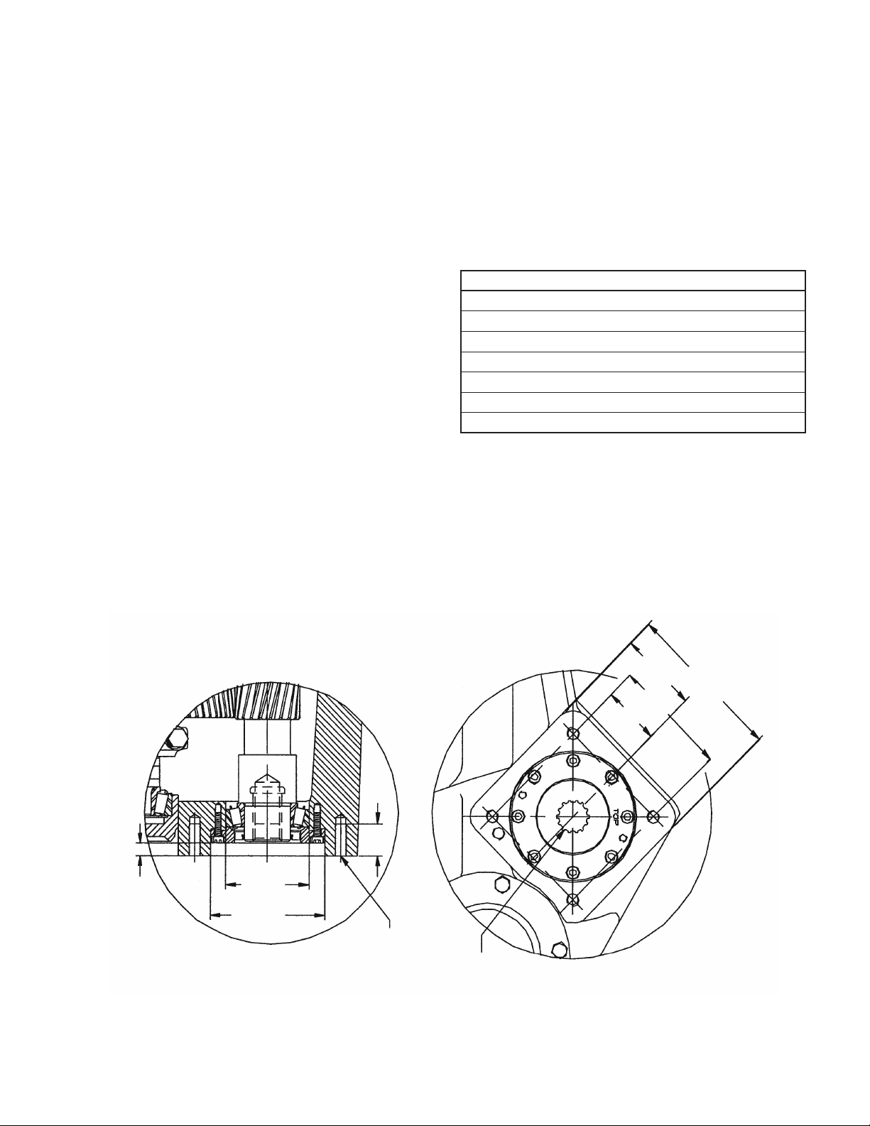
DIMENSIONS, S.A.E. “C” FACE MOUNTING
.540 Pilot Depth
NOTE: Measurements in inches
3.636 DIA.
3.625 DIA.
5.0000 DIA.
5.0020 DIA.
1-3/8
1/2-20UNF-2B
4 (Holes)
14 tooth 12/24
Pitch Involute Spline
2-1/4
3-5/64 TYP.
6-5/32 TYP.
4-1/2 TYP.
TYP.
5
 Loading...