

Page 1
DM™ Filter System Owner's Manual
IMPORTANT SAFETY INSTRUCTIONS
READ AND FOLLOW ALL INSTRUCTIONS
SAVE THESE INSTRUCTIONS
T able of Contents
SECTION I. PUMP SAFETY REMINDER INSTRUCTIONS ...............................................2
SECTION II. HOW YOUR FIL TER WORKS ..........................................................................2
SECTION III. INST ALLA TION................................................................................................. 3
SECTION IV . INITIAL ST ART-UP AND RESTART INSTRUCTIONS.................................6
SECTION V. CLEANING THE FIL TER...................................................................................6
SECTION VI. WINTERIZING THE FIL TER ............................................................................8
SECTION VII. TROUBLE SHOOTING ...................................................................................... 8
SECTION VIII. PUMP INSTRUCTIONS .................................................................................... 9
SECTION IX. TECHNICAL DA T A......................................................................................... 1 1
A. ABOVE GROUND FIL TER SYSTEM........................................................................ 1 1
B . CAR TRIDGE FILTER P AR TS LIST - MODELS DM-75, 90, 120 ............................ 1 2
C . DYNAMO PUMP.......................................................................................................13
Important Notice
Attention Installer. This manual contains important information about the installation,
operation and safe use of this product. This information should be given to the owner/
operator of this equipment.
WARNING
Before installing this product, read and follow all warning notices and instructions accompanying this
filter. Failure to follow safety warnings and instructions can result in severe injury, death, or property
damage. Call (800) 831-7133 for additional free copies of this manual.
Pentair Pool Products
1620 Hawkins Ave., Sanford, NC 27330 • (919) 774-4151
10951 West Los Angeles Ave., Moorpark, CA 93021 • (805) 523-2400
REV. B 7-7-00 1 P/N 175706
Page 2
SECTION I. PUMP SAFETY REMINDER INSTRUCTIONS
When installing and using this electrical equipment, basic safety precautions should always be followed,
including the following:
1. READ AND FOLLOW ALL INSTRUCTIONS.
2 . WARNING - To reduce the risk of injury, do not permit children to use this product unless they are
closely supervised at all times.
3 . WARNING - Risk of Electrical Shock. Connect only to a grounding type receptacle protected by a
ground-fault circuit-interrupter (GFCI). Contact a qualified electrician if you cannot verify that the
receptacle is protected by a GFCI.
4 . Do not bury the electrical cord. Locate the cord to minimize the abuse from lawn mowers, hedge
trimmers, and other equipment.
5 . WARNING - To reduce the risk of electrical shock, replace damaged cord immediately.
6 . WARNING - To reduce the risk of electrical shock, do not use an extension cord to connect unit to
electric supply; provide a properly located outlet.
7 . CAUTION - For continued protection against possible electrical shock, this unit is to be mounted
to the base in accordance with the installation instructions.
8. SAVE THESE INSTRUCTIONS.
WARNING
To reduce the risk of electrical shock, Only connect to a GFCI protected receptacle. Failure to do
so could result in an electrical shock to pool users, installers, or others which can result in
serious personal injury or death.
SECTION II. HOW YOUR FILTER WORKS
Your cartridge filter is designed to produce clear, sparkling water and operate for years with a minimum of
maintenance when installed, operated and maintained in accordance with these instructions.
Your filter uses a cartridge element to remove dirt particles from the water. Dirt is collected in the filter by the
cartridge element as water flows through the filter. Water enters the filter through the filter inlet port and is
distributed evenly through the cartridge element. The dirt is removed by the cartridge fabric and the clean
water flows through the filter outlet port and is returned to the pool through the piping or hoses.
After a period of time, dirt will accumulate in the filter causing a resistance to the flow of water through the
filter. This resistance results in a diminished flow of water and a rise in the filter pressure. Eventually the
filter will have removed so much dirt and the filter pressure risen to such a point that it will be necessary to
clean your filter, see SECTION V. CLEANING FILTER.
The filter’s function is to remove suspended matter from the water and does not sanitize the water. For
sparkling clear water, the water must be sanitized as well as balanced. Pool chemistry is a specialized area,
and you should consult your local pool service specialist for specific details. In general, proper pool
sanitation requires a free chlorine level of 1 to 2 PPM and a PH range of 7.2 to 7.6.
P/N 175706 2 REV. B 7-7-00
Page 3
WARNING
Failure to operate your filter system or inadequate filtration can cause poor water clarity obstructing
visibility in your pool. Poor water clarity may obscure objects in the water which while swimming and
diving could cause severe personal injury and death. Never swim in a pool with poor water clarity.
SECTION III. INSTALLATION
WARNING
THIS FILTER OPERATES UNDER HIGH PRESSURE. WHEN ANY PART OF THE
CIRCULATING SYSTEM (e.g., LOCK RING, PUMP, FILTER, VALVES, ETC.) IS
SERVICED, AIR CAN ENTER THE SYSTEM AND BECOME PRESSURIZED.
PRESSURIZED AIR CAN CAUSE THE LID TO BE BLOWN OFF WHICH CAN RESULT IN
SEVERE INJURY, DEATH, OR PROPERTY DAMAGE. TO AVOID THIS POTENTIAL
HAZARD, FOLLOW THESE INSTRUCTIONS.
1. BEFORE REPOSITIONING VALVES AND BEFORE BEGINNING THE ASSEMBLY,
DISASSEMBLY, OR ADJUSTMENT OF THE LOCK RING OR ANY OTHER SERVICE
OF THE CIRCULATING SYSTEM: (A) TURN THE PUMP OFF AND SHUT OFF ANY
AUTOMATIC CONTROLS TO ENSURE THE SYSTEM IS NOT INADVERTENTLY
STARTED DURING THE SERVICING; (B) OPEN AIR RELIEF VALVE; (C) WAIT
UNTIL ALL PRESSURE IS RELIEVED.
2. WHENEVER INSTALLING THE FILTER LOCK RING FOLLOW THECLEANING
FILTER INSTRUCTIONS EXACTLY.
3. ONCE SERVICE ON THE CIRCULATING SYSTEM IS COMPLETE FOLLOW INITIAL
START SYSTEM RESTART INSTRUCTIONS EXACTLY.
4. MAINTAIN CIRCULATION SYSTEM PROPERLY. REPLACE WORN OR DAMAGED
PARTS IMMEDIATELY (e.g., lock ring, pressure gauge, relief valve, O-rings, etc.).
5. BE SURE THAT THE FILTER IS PROPERLY MOUNTED AND POSITIONED
ACCORDING TO INSTRUCTIONS PROVIDED.
To install this filter system, you will need the following simple tools - a screwdriver, pliers, and wrench.
1 . Carefully remove the equipment from the carton and check for any evidence of damage due to
rough handling or shipping. If any of the equipment is damaged, immediately notify the
organization where the equipment was purchased.
2 . This filter should be mounted on a level concrete slab, preferably concrete poured in a form or on a
platform constructed of concrete block or brick.
REV. B 7-7-00 3 P/N 175706
Page 4
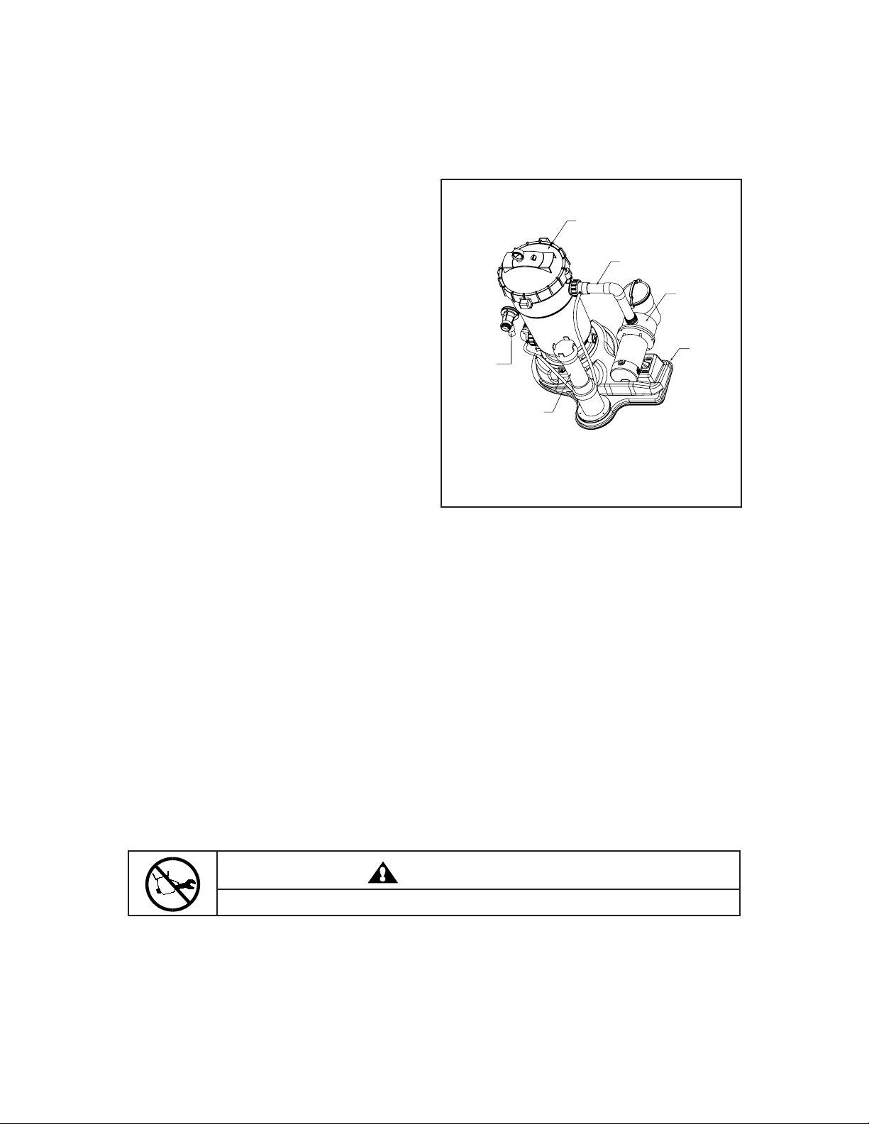
3. Place the pump on the mounting base; see
Diagram 1. Loosely attach the pump
connector to the pump and filter. This will
DM Filter
align the pump to the correct set of mounting
holes. Secure the pump to the base using
two bolt-fasteners. Tighten the union fittings
on the plumbing connector by hand until
Plumbing Kit
Dynamo Pump
tight. If water leakage occurs at these
connections, adjust connections with a
wrench, making sure not to exceed 1/4 of a
turn.
4 . Do not mount electrical controls (on/off
switches, timer, etc.) over the filter. You need
to be able to stand clear of the filter when
starting the pump.
AquaLuminator
Light Ready
Return Fitting
Optional
Chlorinator
AG Base
inlet
5. Attach the hair and lint pot to the front of the
pump. This is an O-ring seal fitting that
requires hand tightening only. (OVER
Diagram 1.
TIGHTENING CAN RESULT IN DAMAGE
TO THE O-RING SEAL)
6 . Install the threaded fitting, see Diagram 2, into the suction port of the pump. This is an O-ring seal
fitting that requires hand tightening only. (OVER TIGHTENING CAN RESULT IN DAMAGE TO
THE O-RING SEAL)
7. Install the threaded return fitting into the filter outlet port, see Diagram 1, making sure that the O-ring is
in place in the filter body. Tighten this connection by hand until tight. If water leakage occurs at this
connection after installation, adjust connection with a wrench making sure not to exceed 1/4 of a turn.
(OVER TIGHTENING CAN RESULT IN DAMAGE TO THE FILTER)
8 . Connect flexible hoses to the equipment and the pool with the clamps.
a. Connect the skimmer suction port from the pool to the pump inlet.
b. Connect the filter outlet port to the return fitting of the pool.
c. Install the pressure gauge using the Teflon tape provided. Wrap the threads of the pressure
gauge with three layers. Install the gauge into the top of the filter tank until tight.
9 . If using the optional Rainbow Chlorine feeder, position the feeder on the system base, aligning the
holes in the feeder base with the three "T" nuts, see Diagram 1. Install the feeder using the three
bolts supplied and tighten.
CAUTION
Do not over tighten.
P/N 175706 4 REV. B 7-7-00
Page 5
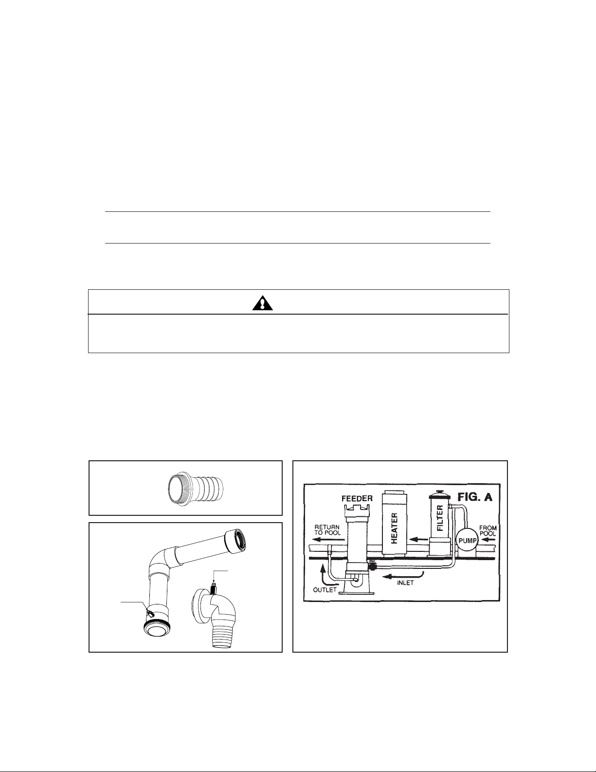
10. Your system includes two (2) special barbed fittings, see Diagram 3, a barbed body swivel and a
barbed return elbow, these fittings must be modified and drilled when installing the chlorine
feeder.
A. Using an 1/8" drill bit; drill a hole through the center of the small protruding barbed port to the
inside of the fitting (this is shipped with the hole blocked), see Diagram 3; this will allow the
water to flow to and from the chlorine feeder. See the Caution below before drilling both
fittings if using a chlorine feeder with a heater.
NOTE
Please use caution in drilling, as not to damage the barbed fitting.
B. Attach the inlet/outlet tubing by first sliding the compression nut over the tubing.
C. Push the tubing over the tapered end of the barb, slide nut to barb, and tighten the nut firmly
by hand.
CAUTION
A highly chlorinated solution should NEVER pass through a heater, if this system was purchased with the
option chlorine feeder and is to be used with a heater, "DO NOT" drill the barbed return elbow. Follow
instruction "D" when installing with a heater.
D . On the return line to the pool from the heater, drill a 1/8" hole in the return pipe and using the
barbed fitting, nut, rubber washers and hose clamp supplied with the chlorine feeder, connect
the outlet tubing from the chlorinator to this connection. This will allow the concentrated
chlorine solution to sanitize your pool while bypassing the heater, see Diagram 4.
11 . The system also includes the AquaLuminator Light Ready Water Return Fitting (P/N 543110,
Diagram 1). To install the light, use the AquaLuminator upgrade kit (P/N 619398). To install the
Light Ready Water Return Fitting, please refer to the installation instructions provided with it.
Diagram 2.
Diagram 3.
Drill a hole through
Drill a hole through
the center of the small
barbed port to the inside
of the fitting.
the center of the small
barbed port to the inside
of the fitting.
Diagram 4.
REV. B 7-7-00 5 P/N 175706
Page 6

SECTION IV. INITIAL START-UP AND RESTART INSTRUCTIONS.
1. Be sure all connections have been made and are secure.
2 . Make sure the hair and lint pot of the pump is filled with water.
LINT POT WITH WATER WILL RESULT IN DAMAGE TO THE PUMP AND PUMP SEAL).
3.
OPEN THE MANUAL AIR RELIEF VALVE UNTIL IT SNAPS INTO THE FULL OPEN POSITION .
4 . STAND CLEAR OF THE FILTER. Start pump allowing the filter tank to fill with water. Close the air
relief valve after a steady stream of water appears.
5 . Your filter has now started its filter cycle. You should check that the water is returning to the pool
and take note of the operating pressure. My original starting pressure is ___________ PSI with the
filter clean.
6 . Check the system for water leaks. If a leak is found, shut off pump before correcting the leak.
(FAILURE TO FILL THE HAIR AND
W ARNING
This filter operates under high pressure. When any part of the circulating system (e.g., lock
ring, pump, filter, valves, etc.) is serviced, air can enter the system and become
pressurized. Pressurized air can cause the lid to be blown off which can result in severe
injury, death, or property damage.
7 . As the filter removes dirt and impurities from the pool water, the accumulation will cause the filter
pressure to rise and the flow to diminish. When the pressure gauge reading is 8 to 10 PSI higher
than the clean filter reading noted above, it is time to clean the filter’s element grids, see SECTION
V. CLEANING THE FILTER, below.
SECTION V. CLEANING THE FILTER
1 . Cleaning frequency will vary from pool to pool and with other factors such as weather conditions,
heavy rains, dust pollen, bather load and water chemistry. Check the pressure gauge reading on a
regular basis and when the pressure gauge reading increases 8 to 10 PSI over the initial clean filter
reading, it is time to clean your CARTRIDGE ELEMENT.
2. Turn the pump off, shut off any automatic controls to assure that the system is not inadvertently
started during servicing.
3. Plug the skimmer port with a rag. This will prevent pool water from running out during servicing.
4 . Open the filter manual air relief valve, and the filter drain plug.
5. Remove the hair and lint strainer pot lid and clean the basket. Replace the basket and secure the lid.
6 . Remove the filter lock ring by depressing the two spring loaded locking blocks and rotating the ring
counter clockwise until the ring is free from the filter body.
7 . Remove the filter lid using the lifting handles on the lid.
P/N 175706 6 REV. B 7-7-00
Page 7

8 . Remove the CARTRIDGE ELEMENT assembly from the filter body by using the lifting handles and
pulling straight up.
9 . Remove the CARTRIDGE ELEMENT from the core assembly by placing your middle fingers into
cloth area and using your thumbs on top of the lifting handles and pressing until the CARTRIDGE
ELEMENT is loose and freely slides off the center core assembly.
10. Using a garden hose, direct water spray at the CARTRIDGE ELEMENT to dislodge and wash away
any accumulated foreign matter. Thoroughly clean the elements.
11. Clean and remove debris from the inside of the filter tank.
12 . Replace the CARTRIDGE ELEMENT over the center core assembly making sure the end of the
element with the wording ‘This Side Up’ is facing up.
13 . Replace the CARTRIDGE ELEMENT into the filter tank body making sure the arrow on the top of
the center core is aligned with the filter inlet port. You will be able to feel the assembly drop into
and lock into place when in the proper position.
14 . Clean any debris from the O-ring at the top of the filter tank. Apply a silicone lubricant to the O-ring.
DO NOT USE A PETROLEUM-BASE LUBRICANT ON THE O-RING.
Failure to properly clean and lubricate the O-ring may result in water leakage.
15. Replace the filter tank lid making sure it is fully and firmly seated on the tank body.
16. Place the filter lock ring over the filter lid, and turn clockwise until the safety latches click and the
lock ring hits the stops on the body.
DO NOT ATTEMPT TO OVER TIGHTEN THE FILTER LOCK RING AFTER THE SAFETY LATCHES HAVE
ENGAGED.
W ARNING
If the filter lock ring is damaged, replace it immediately.
This filter operates under high pressure. Replace locking ring if damaged or worn. Failure
to replace locking ring can result in the lid separating from the filter which can cause
severe injury or death.
17. Replace the drain cap hand tight only.
18. Follow Initial Start Up and System Restart Instructions; see Section IV.
WARNING
Failure to operate your filter system or inadequate filtration can cause poor water clarity obstructing
visibility in your pool. Poor water clarity may obscure objects in the water which while swimming and
diving could cause severe personal injury and death. Never swim in a pool with poor water clarity.
REV. B 7-7-00 7 P/N 175706
Page 8

SECTION VI. WINTERIZING THE FILTER
1 . In areas that have freezing winter temperatures, the pool equipment must be winterized to protect it
from damage.
2 . With the pump turned off, open the manual air relief valve.
3 . Remove the drain port cap, and allow the filter to drain completely.
4 . Remove the drain port plugs on the pump and allow the pump to drain completely.
5 . Drain all appropriate system piping.
6 . It is recommended that the pump and filter be covered with a tarpaulin or plastic sheet to inhibit
deterioration from the weather.
DO NOT WRAP THE PUMP MOTOR WITH PLASTIC.
7 . Your filter system is now winterized.
8 . See SECTION IV. INITIAL START-UP AND SYSTEM RESTART, when pool is ready to be opened
for the season.
SECTION VII. TROUBLE SHOOTING
Problem Cause Remedy
Pool water not 1. Pool chemistry not adequate to inhibit algae growth. Maintain pool chemistry or consult pool service technician.
sufficiently clean. 2. Inadequate turnover rate. Run system for longer time or consult dealer or pool service
technician.
Higher filter pressure. 1. Insufficient cleaning of the filter element. Clean the filter element (see Cleaning Filter instructions).
2. Partially closed valve or restriction. Open valve or remove obstruction in return line.
Short filter cycles. 1. Insufficient cleaning of filter element. Clean the filter element (see Cleaning Filter instructions).
2. Pool chemistry not adequate to inhibit algae growth. Maintain pool chemistry or consult pool service technician.
3. Flow rate too high. Restrict flow to capacity of filter.
Return flow to pool 1. Obstruction in the pump hair and lint pot. Clean basket in strainer.
diminished, low filter 2. Obstruction in pump. Disassemble and clean pump.
pressure. 3. Obstruction in suction line to pump. Clean skimmer basket. Remove obstruction in lines. Open
valves in suction line.
P/N 175706 8 REV. B 7-7-00
Page 9

SECTION VIII. PUMP INSTRUCTIONS
Systems are supplied with the Dynamo Pump.
1 . TO PRIME PUMP - (pump must be off).
Unscrew the lid from the pot and fill the pot with water to level of the suction line. Inspect O-ring,
lubricate with silicone lubricant. Replace lid and hand tighten, lid shoulder will come to rest on the
pot surface. Turn the pump on, priming time will vary depending upon elevation above water level
and horizontal distance of suction line. If the filter is installed, open the air relief valve (before
turning the pump on) until a steady stream of water comes out, then close the air relief valve. The
pump is now primed. If the pump is installed below water level, close the return line prior to filling the
hair and lint pot with water. Line must be reopened before turning the pump on.
WARNING
To reduce the risk of electrical shock, only connect to a GFCI protected receptacle. Failure to do
so could result in an electrical shock to pool users, installers, or others which can result in
serious personal injury or death.
2 . TO CLEAN BASKET - (pump must be off)
Follow the instructions above to prime the pump. After removing the lid, remove the basket and
empty the debris. Replace the basket and proceed to fill the pot with water. It is important to
visually inspect the basket, through the see through lid, at least once a week. A dirty basket will
reduce the efficiency of your system, and can put an abnormal load on the pump which could result
in costly repair bills.
3 . SHAFT SEAL - (rotary seal). The shaft seal consists of two parts:
a. Rotating ceramic seal, press fitted into the impeller.
b. A stationary spring loaded seal, press fitted into the rear of the volute.
REV. B 7-7-00 9 P/N 175706
Page 10

4. THE ELECTRIC MOTOR.
a. The electric motor should be protected from foreign matter, water splashing, hosing, and the weather.
Enclosures should be well ventilated to prevent overheating. If a motor becomes wet, permit it to dry
before running it. If a motor has been damaged by water or dirt, the warranty is void.
b. The motors used on these pumps are 48 frame through bolt motors. The through bolts are
used to secure the volute to the motor. When replacing the motor, mark the end bells and the
motor shell to indicate alignment. Remove the four nuts from the through bolts at the shaft
end. Place the shaft through the back of the volute and locate the bolts in line with the brass
inserts located in the four legs at the rear of the volute. Be sure the end bell and the shell
marking line up. Securely fasten the motor to the volute.
c. Protect the motor from heat. Provide ample ventilation.
CAUTION
The highly polished and lapped faces of the seal are easily damaged. Handle with care.
This centrifugal pump requires little or no service, however the shaft seal will wear with normal use
over the years and will require periodic replacement.
CAUTION
DO NOT RUN PUMP DRY. If the pump is run dry, the mechanical seal will be damaged and external
leakage will occur. When a seal is damaged, the seal must be replaced.
CAUTION
ALWAYS MAINTAIN PROPER WATER LEVEL IN THE POOL. Water level must be half way up the skimmer
opening. A low water level can cause the pump motor to run dry which will damage the mechanical seal and
cause external leakage.
P/N 175706 10 REV. B 7-7-00
Page 11

SECTION IX. TECHNICAL DATA
A. Above Ground Filter System Parts List
1
2
Item Part Description Qty.
No. No.
1 175708 Plumbing Kit 1
2 150045 Body Swivel 1
4
3 39107400 Barbed Return Elbow 1
4 150043 Base AG System 1
5 R171016 Rainbow Chlorine Feeder, Model 300 1
6 619398 AquaLuminator Upgrade Kit 1
3
Above Ground DM, Dynamo System
(Optional)
Non-Return Light for Above Ground Pools
5
6
REV. B 7-7-00 11 P/N 175706
Page 12

SECTION IX. TECHNICAL DATA, (continued)
B. Cartridge Filter Parts List - Models DM-75, 90, 120
30
40
50
20
10
60
0
1
2
3
4
5
6a
6b
PSI
16
15a
15b
15c
15d
14
Item Part Description Qty.
No. No.
1 175666 Knob, Air Release 1
2 175687 O-Ring Air Release 1
15
3 170010 Lid 75 / 90 / 120 Assy. 1
4 59014700 Air Bleed Stock 1
5 59011700 Clamp Air Bleed 1
6 175664 Core Cartridge Assy., 75 / 90 / 120* 1
6a Cap - Cartridge Core 1
Not
6b Core Cartridge 2
Sold
6c Tube 1/2" Dia. Acrylic, 75 / 90 / 120 21.5"
Separately
6d Dust Collector 1
7 170012 Tank Assy. 1
8 175679 Knob - Drain Port 1
9 175680 O-Ring Drain Port 1
10 98212200 Union Nut 2
11 39104500 Union Nut "C" Clip 2
6
12 175674 Diffuser - Inlet 1
13 178568 O-Ring 2-451 1
6c
14 175689 Cartridge 75 - Model DM-75 1
14 175652 Cartridge 90 - Model DM-90 1
6d
13
12
11
7
10
14 175653 Cartridge 120 - Model DM-120 1
15 175667 Ring Assy. 1
15a Ring 1
Not
15b Spring Lock Ring 2
Sold
15c Lock Ring Block 2
Separately
15d Fastener Grip .250 2
16 53003201 Gauge, Pressure 1
* Includes #4, 5, 6a, 6b, 6c, 6d.
9
8
P/N 175706 12 REV. B 7-7-00
Page 13

SECTION IX. TECHNICAL DATA (continued)
C. DYNAMO PUMP
14
13
12
15
11
9
10
Find Part Description
No. No.
Motors
1 35-6497 ¾A std. 48 frame thru-bolt 115 only
1 35-6495 1A std. 48 frame thru-bolt 115 only
1 35-6469 1½A std. 48 frame thru-bolt 115/230
1 35-6445 2 std. 48 frame thru-bolt 115/230 28 lbs.
2 35-4632 Diffuser - ¾ hp bracket
2 35-4633 Diffuser - 1, 1½ hp bracket
3 35-4542 Nut - 10-24 s/s, 6 req.
4 35-4634 O-ring - 3/16 in. bracket diffuser
5 35-4545 Seal - 5/8 in. Mechanical
6 35-3002 Impeller - 1½ hp
6 35-4552 Impeller - ¾ hp
6 35-5122 Impeller 1, 1½ hp
9
8
7
Replacement Parts
Find Part Description
No. No.
7 35-4630 Housing, body
8 35-4541 Screw10-24-1½ in. slotted hex, 6 req.
9 15-4481 Plug - ¼ in. drain, 2 req.
10 27-3062 O-ring
11 35-4530 Pot
12 35-4548 Basket w/handle
13 35-4533 O-ring, lid
14 35-4531 Lid- universal
15 35-4103 Pot assy.
Not Shown
35-4583 Adaptor, 1½ in. thrd.
35-2257 Adaptor, 1½ in. quick connect, 2 req.
35-2256 Nut, 1½ in. quick connect, 2 req.
35-4571 O-ring, 2 req.
1
2
3
4
5
6
SAVE THESE INSTRUCTIONS.
REV. B 7-7-00 13 P/N 175706
Page 14

P/N 175706 14 REV. B 7-7-00
 Loading...