

Pentair 3V10M4-21, 3V10M4-03, 3V10M4-23, 3V10M4-53, 3V10M4-43 Installation And Service Manual
...
INSTALLATION AND SERVICE MANUAL
MYERS
SUBMERSIBLE SOLIDS
HANDLING PUMPS
ENGLISH: PAGES 2-12
Installation and Service Manual
For use with product built with Regal motor.
NOTE! To the installer: Please make sure you provide
this manual to the owner of the equip ment or to the
responsible party who maintains the system.
Models
3V(X*), 3R(X*),
3RH(X*), 4V(X*)
and 4R(X*)
Used in Hazardous Locations Class I,
Division 1, Groups C & D
(*Hazardous Location
Motor End)
3RHX Shown
NOTE! To the installer: Please make sure you provide this manual to the owner of the equip ment or to the responsible
party who maintains the system.
Part # 23833A659 | © 2019 Pentair plc. | 01/07/19

CAUTION!
Read these safety warnings rst before installing, servicing
or operating any pump.
CALIFORNIA PROPOSITION 65 WARNING:
This product and related
accessories contain chemicals known to the
State of California to cause cancer, birth
defects or other reproductive harm.
GENERAL
Most accidents can be avoided by using common sense.
Read the operation and maintenance instruction manual
supplied with the pump.
Do not wear loose clothing that can become entangled in
the impeller or other moving parts.
This pump is designed to handle materials that could
cause illness or disease through direct exposure.
Wear adequate protective clothing when working on the
pump or piping.
ELECTRICAL
To reduce the risk of electrical shock, pump must be
properly grounded in accordance with the National
Electric Code and all applicable state and local codes
and ordinances.
To reduce risk of electrical shock, disconnect the pump
from the power source before handling or servicing.
Any wiring to be done on pumps should be done by a
qualied electrician.
Never operate a pump with a power cord that has frayed
or brittle insulation.
Never let cords or plugs lie in water.
Never handle connected power cords with wet hands.
PUMPS
Pump builds up heat and pressure during operation;
allow time for pump to cool before handling or servicing.
Only qualied personnel should install, operate or
repair pump.
Keep clear of suction and discharge openings. Do not
insert ngers in pump with power connected.
Do not pump hazardous material not recommended for
pump (ammable, caustic, etc.).
Make sure lifting handles are securely fastened each
time before lifting.
Do not lift pump by the power cord.
Do not exceed manufacturer's recommendation for
maximum performance, as this could cause the motor
to overheat.
Secure the pump in its operating position so it cannot
tip over, fall or slide.
Keep hands and feet away from impeller when power is
connected.
Submersible solids handling pumps are not
approved for use in swimming pools, recreational water
installations, decorative fountains or any installation
where human contact with the pumped uid is common.
Do not operate pump without safety devices in place.
IMPORTANT! Myers® is not responsible for losses, injury
or death resulting from a failure to observe these safety
precautions, misuse or abuse of pumps or equipment.
GENERAL INFORMATION:
Pump Models: These instructions cover the installation
and service of the Myers pumps as listed on the front
cover. The hazardous location models are Factory Mutual
approved and listed hazardous location for hazardous
sewage locations Class 1, Division 1, Groups C,D.
Motor HP & Voltages: These pumps are offered in a
three phase wiring conguration only. Voltages will vary
according to the application.
Electrical Controls: All of these pump models must be
used with a control panel. These control panels must be
obtained from Myers or must be approved by Myers or
warranty on pump is void.
General Construction: The motor construction is
designed to meet Factory Mutual’s requirements for
Class 1, Division 1, Groups C,D sewage applications.
The hazardous location models are certied and
nameplated with this approval. The motor chamber and
seal chamber are lled with a high dielectric type oil for
improved lubrication and heat transfer of the bearings
and motor. Since the bearings have been designed
for 50,000 hours of life, the oil should never require
replacement under normal operating conditions. An
air space above the oil level in both the seal and motor
chambers is provided to allow for the expansion of the
oil when at operating temperature. The power and
control lines are sealed and strain relieved by grommet
in the cord cap, and internally through the use of a
dielectric potting resin surrounding the electrical wires.
All of the pump fasteners and shafts are made from
corrosion resistant stainless steel, while the pump
castings are made of ASTM A-48 Class 30 cast iron.
2
General Installation: Various congurations and
methods of plumbing this series of solids handling
pumps may be used; however, for ease of installation
and service a Myers® 3" or 4" rail lift-out system is
recommended.
Note: If the hazardous location pumps are used in
conjunction with a rail lift-out system, it must be an
FM approved nonsparking, hazardous location system.
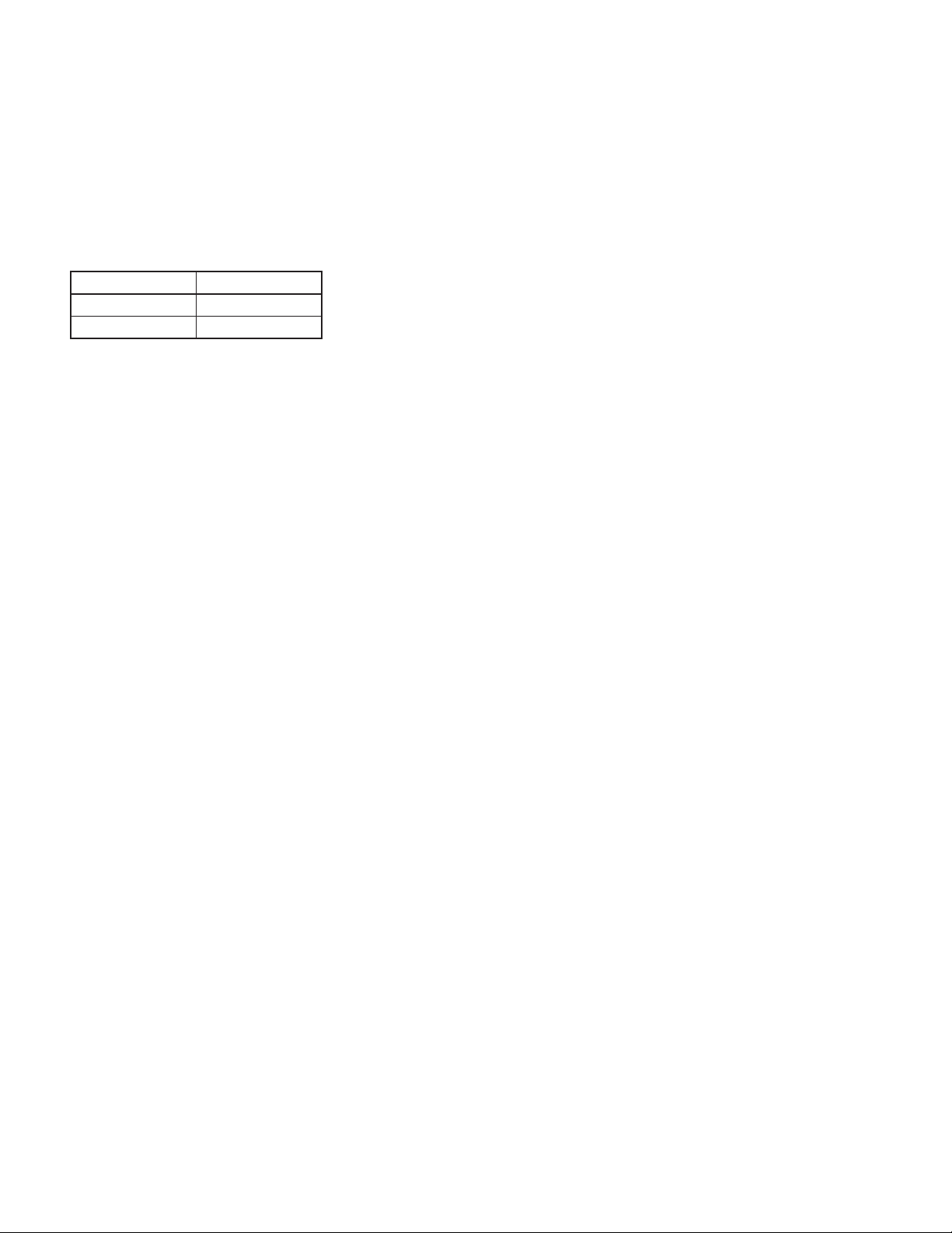
The Myers approved lift-out models are:
3" Liftout 4" Liftout
SRAX3030 SRAX4040
SRAX33HH SRAX44HH
The presence of water energizes a red seal leak warning
light at the control panel. This is a warning light only,
and does not stop the motor. It indicates a leak has
occurred and the pump must be repaired. Normally, this
indicates the outboard seal has leaked. Allowing the
unit to operate after the warning could cause upper seal
leakage along with motor failure.
The resistance across the moisture sensing (seal failure)
probes should be checked after a seal leak warning
light has lit. This can be done by disconnecting the
red and orange control wires from the control panel,
and measuring the resistance with an ohmmeter
between the wires. If the measured values are below
specication, the pump may have a lower seal failure
and require service.
If these guidelines are not followed, the Factory Mutual
approval is void.
Hazardous Location Service: These pumps are to be
used for handling sewage, wastewater and storm water
only. Do not use in other hazardous locations. These
pumps must be repaired and serviced only at Myers
authorized service centers or at the Myers factory.
Any unauthorized eld repair voids warranty, hazardous
location rating and Factory Mutual approval.
CAUTION: After the pump is installed and sewage has
entered the basin there are methane and hydrogen
sulde gases, which are poisonous. Never enter a wet
well unless the cover is open for a sucient period of
time to allow fresh air into the basin. Myers recommends
using the rail lift-out system so that no service is
required inside the basin.
Motor: Each motor is provided with heat sensor
thermostats attached directly to the motor windings.
The thermostats open if the motor windings see
excessive heat and, in turn, open the motor contactor
in the control panel, breaking the power to the pump.
When the motor is stopped due to an overheated
condition, it will not start until the motor has cooled
and the heat sensor reset button is manually pushed
on the front of the Myers control panel. This circuitry
is provided in the Myers control panel designs.
Thermostats are set to open at a temperature of 248°F
(120°C). The maximum contact rating is 18 amps at 115
VAC and 12 amps at 230 VAC. Motor winding insulation
is good for Class F (311°F, 155°C).
Note: Failure to use proper circuitry and to connect the
motor overheat protection in the control panel would
negate all warranties and FM approval.
Motor Seal Failure Warning: The seal chamber is oil
lled and provided with moisture sensing probes to
detect water leakage through the lower shaft seal. The
probes can also detect moisture present in the upper
motor housing.
On the Myers hazardous location control panels the seal
leak test switch tests the seal leak circuit continuity.
When pushed, the seal leak test bulb should light. If
the test bulb does not light it means either the wiring
circuitry to the seal leak probes has been broken or the
bulb has burned out.
Note: Myers control panels supply the correct circuitry
for moisture and heat sensor connections. Failure to
install the correct circuitry with proper connection
would negate warranty and FM approval.
Motor Power Cord, Control Cord and Cord Cap
Assembly: Each motor power cord has 4 conductors:
white, black, red and green. For a three phase motor the
red, black and white conductors connect to the three
line leads, and the green is connected to a good ground.
Interchanging any two line leads will reverse the rotation
of the motor.
Note: Rotation should be clockwise when observed
from the top of the pump. This can be checked by noting
which direction the pump torque is up on initial starting.
A properly rotating pump will torque counterclockwise
upon start.
The control cable has 5 conductors: black, white, red,
orange and green. White and black connect to the heat
sensor terminals in the control panels; red and orange
connect to the seal failure terminals in the control
panel; and the green connects to the ground in the
control panel.
The cord cap is epoxy potted. The cord cap provides
for a sealed wire connection. This allows the cord
cap, with cords, to be removed from the motor. An
approved hazardous location junction box is required
for hazardous locations. The control and power cables
cannot be spliced!
Note: Each cable has a green ground wire and must be
properly grounded per the National Electric Code and
local codes.
3

Electrical Motor Controls: All electrical controls and
motor starting equipment should be as specied in
these instructions. Consult factory for any acceptable
alternatives. For hazardous locations the controls and
control panel must be installed outside the hazardous
area, or approved hazardous location controls that are
intrinsically safe must be used.
Junction Box: If a junction box is used in a hazardous
location, it must be a hazardous location approved
type with hazardous location cord connectors. Wires
from the junction box must pass through a hazardous
location seal connector.
Level Sensing Controls: Intrinsically safe type oat
controls are recommended for all applications and
required for hazardous location service. An intrinsically
safe control panel relay will limit the current and voltage
to the level controls. A Myers® control panel can be
supplied with this type circuitry.
The oat level controls maintain the basin sewage water
level by controlling pump turn-on and turn-off levels.
The lower turn-off control should be set so that the
pump stops at approximately the top of the pump.
Consult the factory for any settings below this point.
The upper turn-on control should be set above the lower
turn-off control. The exact height between the two
controls is determined by the number of pump starts
desired and the depth of the basin. A maximum of 10
starts per hour should not be exceeded.
The override control is set at a specied height above
the upper turn-on control.
The alarm control is set about 6" to 12" above the
override control.
No control should be set above the inlet invert.
Electrical Connections: All electrical wiring must
be in accordance with local code and only qualied
electricians should make the installations. All wires
should be checked for shorts to ground with an
ohmmeter or megger after the connections are made.
This is important, as one grounded wire can cause
failure of the pump, control panel or personal injury.
Disassembly
With the pump located in a secure place, remove the
bolts fastening the seal housing to the volute. The
motor and impeller can now be removed as a unit.
Lay the unit down on its side. If the lower seal is to be
removed, it is recommended that the oil in the seal
chamber be drained. This can be done by removing
the lower seal chamber plug and draining the oil into a
holding container.
To remove the impeller: Using a proper wrench, the
impeller retaining bolt and washer must be removed.
This may require a piece of wood placed between the
vanes to keep the impeller from rotating while removing
the bolt. Once the bolt has been removed, tap lightly with
a hammer around the outside diameter of the impeller to
loosen from shaft and key. After removing impeller, the
seal retainer needs to be removed to expose seal.
Caution: The impeller is large and heavy and will need to
be supported.
If the lower seal needs removed, rst remove the
compression spring that rides between the impeller and
the seal assembly. Next, take a pair of screwdrivers and
remove the compression ring that surrounds the rubber
bellows on the rotating portion of the seal assembly.
Again using the screwdrivers, pry the remaining portion
of the rotating seal assembly off the shaft. The ceramic
stationary can be removed by placing a screwdriver
between the rubber and the ceramic face, and then
prying, working around the entire diameter. Note,
these parts should be discarded and a new seal
assembly installed.
If the oil in the seal chamber was drained, examine
the contents to determine if the upper seal has been
damaged. Signs of grit or other abrasive material may
indicate that the upper seal has also been damaged.
Pressurizing the motor housing assembly between 7 and
10 psi and observing any drop in pressure will indicate if
the upper seal is functioning properly.
Note: Upper seal repairs must be done at a Myers
authorized service center or at the Myers factory.
Any unauthorized eld repair voids warranty and the
hazardous location approval on the Factory Mutual listed
pump.
The wear ring can be removed from the volute for repair
or replacement. First remove the retaining screws from
the wear ring. With a soft mallet the wear ring can be
tapped out of the volute case.
Reassembly
Remove the ceramic portion of the new seal from the
package. Brush new dielectric oil or glycerine around
the rubber portion of the stationary assembly and into
the pocket in the seal housing. Note, keep the oil off the
seal face. Without scratching the seal face, press the
ceramic stationary portion into the seal housing using a
Myers seal pusher. With clean cloth, lightly wipe the face
of the seal surface to make sure it is dirt free. Remove
the rotating portion of the seal from the package and
lubricate the inside diameter of the rubber bellows
and the outside diameter of the shaft. Place the seal
over the shaft (make sure the key is removed). Evenly
press on the body of the rotational assembly and slide
it down the shaft until the seal faces meet. Once the
seal assembly is in position, place the spring over the
register on the rotational portion of the seal.
Before placing impeller on shaft, the seal spring retainer
should be placed on shaft with stepped end toward seal
spring. Position the key into the seat in the shaft. Align
the impeller onto the shaft, making sure that the seal
spring is registered properly onto the back side of the
impeller. Insert the bolt and washer assembly into the
shaft and tighten to 43 ft.-lbs.
4
 Loading...