

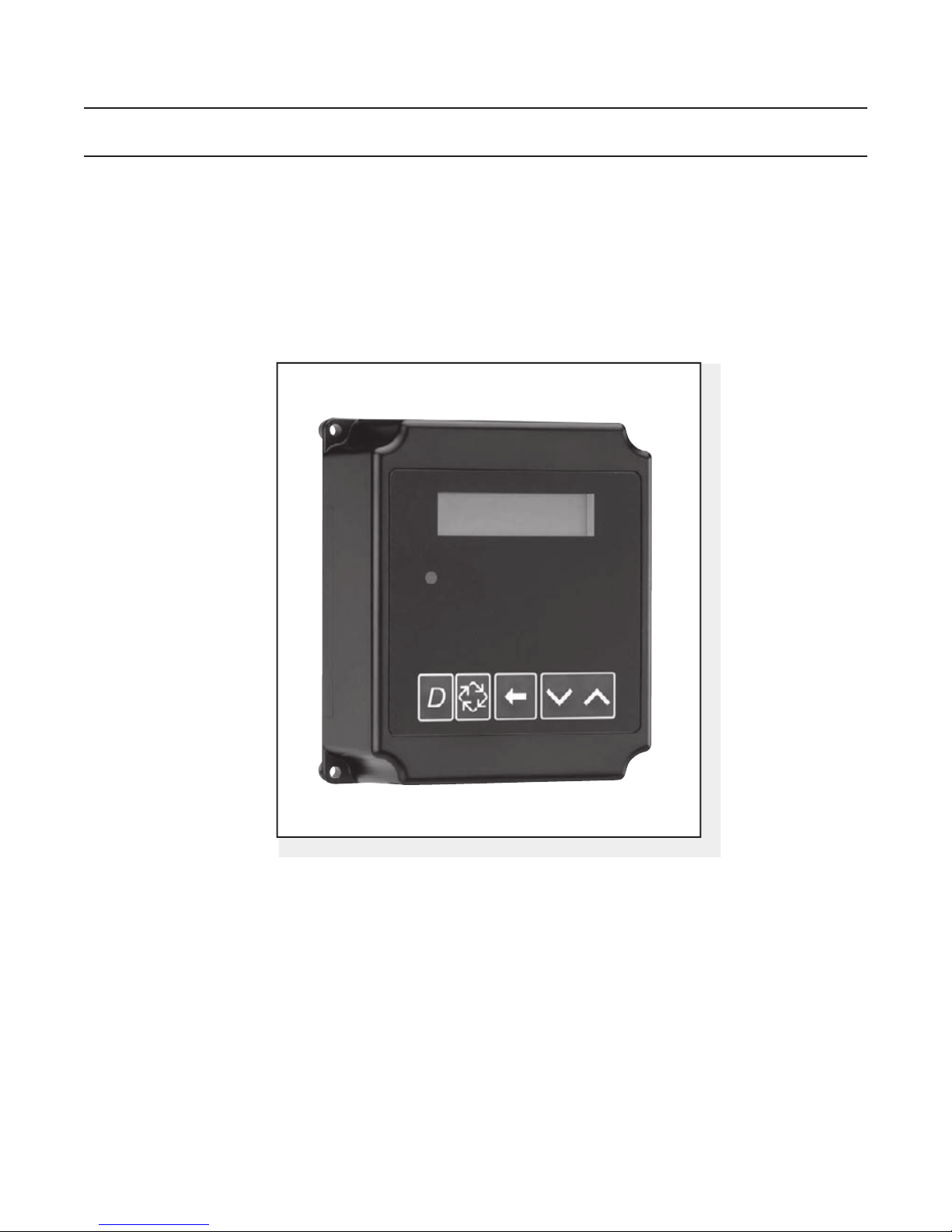
3200NXT
Service Manual
IMPORTANT: Fill in Pertinent Information on Page 3 for Future Reference
Table of Contents
Job Specication Sheet ......................................................................................................................................... 3
Timer Operation ..................................................................................................................................................... 4
Timer Display Features ......................................................................................................................................... 6
Timer Display - Screen Examples ......................................................................................................................... 7
Network/Communication Cables & Connections ................................................................................................... 8
Master Programming Mode Flow Chart................................................................................................................. 9
Master Programming Guide ................................................................................................................................ 13
User Mode Programming Flow Chart .................................................................................................................. 20
Diagnostic Mode Flow Chart ............................................................................................................................... 21
Diagnostic Programming Guide........................................................................................................................... 22
2750/2850/2900 Upper & 2900 Lower Powerhead Assy ..................................................................................... 26
3150/3900 Upper & 3900 Lower Drive Powerhead Assy .................................................................................... 28
2750/2850/3150 Input & Output Wiring ............................................................................................................... 30
2900/3900 Input & Output Wiring ........................................................................................................................ 31
Troubleshooting ................................................................................................................................................... 32
IMPORTANT PLEASE READ:
The information, specications and illustrations in this manual are based on the latest information available at the time of •
printing. The manufacturer reserves the right to make changes at any time without notice.
This manual is intended as a guide for service of the valve only. System installation requires information from a number of •
suppliers not known at the time of manufacture. This product should be installed by a plumbing professional.
This unit is designed to be installed on potable water systems only.•
This product must be installed in compliance with all state and municipal plumbing and electrical codes. Permits may be •
required at the time of installation.
If daytime operating pressure exceeds 80 psi, nighttime pressures may exceed pressure limits. A pressure reducing valve must •
be installed.
Do not install the unit where temperatures may drop below 32°F (0°C) or above 110°F (43°C). •
Do not place the unit in direct sunlight. Black units will absorb radiant heat increasing internal temperatures. •
Do not strike the valve or any of the components.•
Warranty of this product extends to manufacturing defects. Misapplication of this product may result in failure to properly •
condition water, or damage to product.
A prelter should be used on installations in which free solids are present. •
In some applications local municipalities treat water with Chloramines. High Chloramine levels may damage valve components.•
Correct and constant voltage must be supplied to the control valve to maintain proper function.•

Job Specication Sheet
Please Circle and/or Fill in the Appropriate Data for Future Reference:
Programming Mode:
Feed Water Hardness: __________ Grains per Gallon or Degrees
Regeneration Time: Delayed __________ AM/PM or __________ Immediate
Regeneration Day Override: Off or Every __________ Days
Time of Day: __________
Master Programming Mode:
Valve Type: 2750 / 2850 / 2900s / 3150 / 3900 / Stager
Regenerant Flow: Downow / Upow Brine Draw First / Upow Brine Fill First
Valve Address: #1 / #2 / #3 / #4
Display Format: US Gallons or m
Unit Capacity: __________ Grains or Degrees
Capacity Safety Factor: Zero or __________ %
3
Feed Water Hardness: __________ Grains or Degrees
System Size: 1 Valve / 2 Valves / 3 Valves / 4 Valves
Regeneration Cycle Step #1: _ _ : _ _ : _ _
Regeneration Cycle Step #2: _ _ : _ _ : _ _
Regeneration Cycle Step #3: _ _ : _ _ : _ _
Regeneration Cycle Step #4: _ _ : _ _ : _ _
Regeneration Cycle Step #5: _ _ : _ _ : _ _
Timed Auxiliary Relay Output Window:
Off or Start Time _ _ : _ _ : _ _
End Time _ _ : _ _ : _ _
Chemical Pump Output Auxiliary Relay: Off or Volume (Gallons or M3)
Time: _ _ : _ _ : _ _
Fleck Flow Meter Size: Paddle: 1” 1.5” 2” 3”
Turbine: 1” 1.5”
Generic Flow Meter: Maximum Flow Rate:
Add _ _ _ Gallons every _ _ _ Pulses
Page 3
Timer Operation
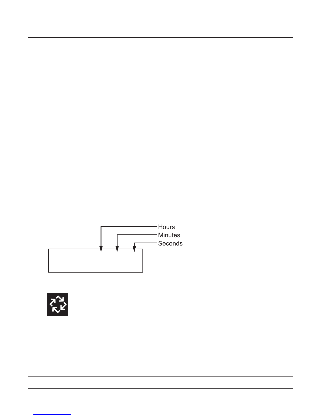
CYCLE 1 00:00:00
BACK WASH
Setting the Time of Day
NOTE: Set Time of Day on the Lead Unit (#1) and the rest of the units in the system will populare with the
Time of Day within 10 seconds.
Press and hold the Up or Down button for 2 seconds. 1.
Press the Shift button to select the digit you want to modify.2.
Press the Up or Down buttons to adjust the value.3.
Press the Extra Cycle button to return to the normal display screen, or after a 5 second timeout.4.
NOTE: The “D” button (Diagnostic) can be pressed to exit without saving.
Manually Initiating a Regeneration
When timer is in service or stand by, press the Extra Cycle button for 5 seconds on the main screen.1.
The timer advances to Regeneration Cycle Step #1, and begins programmed time count down.2.
Press the Extra Cycle button once to advance valve to Regeneration Cycle Step #2 (if active).3.
Press the Extra Cycle button once to advance valve to Regeneration Cycle Step #3 (if active).4.
Press the Extra Cycle button once to advance valve to Regeneration Cycle Step #4 (if active).5.
Press the Extra Cycle button once to advance valve to Regeneration Cycle Step #5 (if active).6.
Press the Extra Cycle button once more to advance the valve back to in service.7.
NOTE: A manually initiated or queued regeneration can be cleared by pressing the Extra Cycle button for less
than 5 seconds. A system queued regeneration can only be cleared by stepping through a manual regeneration. If
regeneration occurs for any reason prior to the delayed regeneration time, the manual regeneration request shall
be cleared. Pressing the Extra Cycle button while in regeneration will cause the upper drive to advance to the next
step immediately.
Timer Operation During Regeneration
In the Regeneration Cycle Step display, the timer shows the current regeneration cycle number the valve is on, or
has reached, and the time remaining in that step. Once all regeneration steps are complete the timer returns to in
Service and resumes normal operation.
Example: 12 Minutes Remaining in Cycle 1 (Back Wash)
Press the Extra Cycle button during a Regeneration Cycle to immediately advance the
valve to the next cycle step position and resume normal step timing.
Flow Meter Equipped Timer
During normal operation, the Time of Day screen alternates with the error screen (if errors are present).•
As treated water is used, the Volume Remaining display counts down from the calculated system capacity to •
zero. When this occurs a Regeneration Cycle begins if no other units are in regeneration.
Page 4
Timer Operation
Timer Operation During Programming
The timer enters the Program Mode in standby or service mode as long as it is not in regeneration. While in the
Program Mode the timer continues to operate normally monitoring water usage. Timer programming is stored in
memory permanently.
Timer Operation During A Power Failure
All program settings are stored in permanent memory. Current valve position, cycle step time elapsed, and time of
day are stored during a power failure, and will be restored upon power re-application. Time is kept during a power
failure, and time of day is adjusted upon power up (as long as power is restored within 12 hours).
NOTE: The time of day on the main display screen will ash for 5 minutes when there has been a power outage.
The ashing of the time of day can be stopped by pressing any button on the display.
Remote Lockout
The timer does not allow the unit/system to go into Regeneration until the Regeneration Lockout Input signal to
the unit is cleared. This requires a contact closure to activate the unit. The recommended gauge wire is 20 with a
maximum length of 500 feet. See P4 remote inputs in the wiring diagrams in the service manual.
Regeneration Day Override Feature
If the Day Override option is turned on and the valve reaches the set Regeneration Day Override value, the
Regeneration Cycle starts if no other unit is in Regeneration. If other units are in regeneration, it is added to a
regeneration queue. This occurs regardless of the remaining volume available.
Page 5
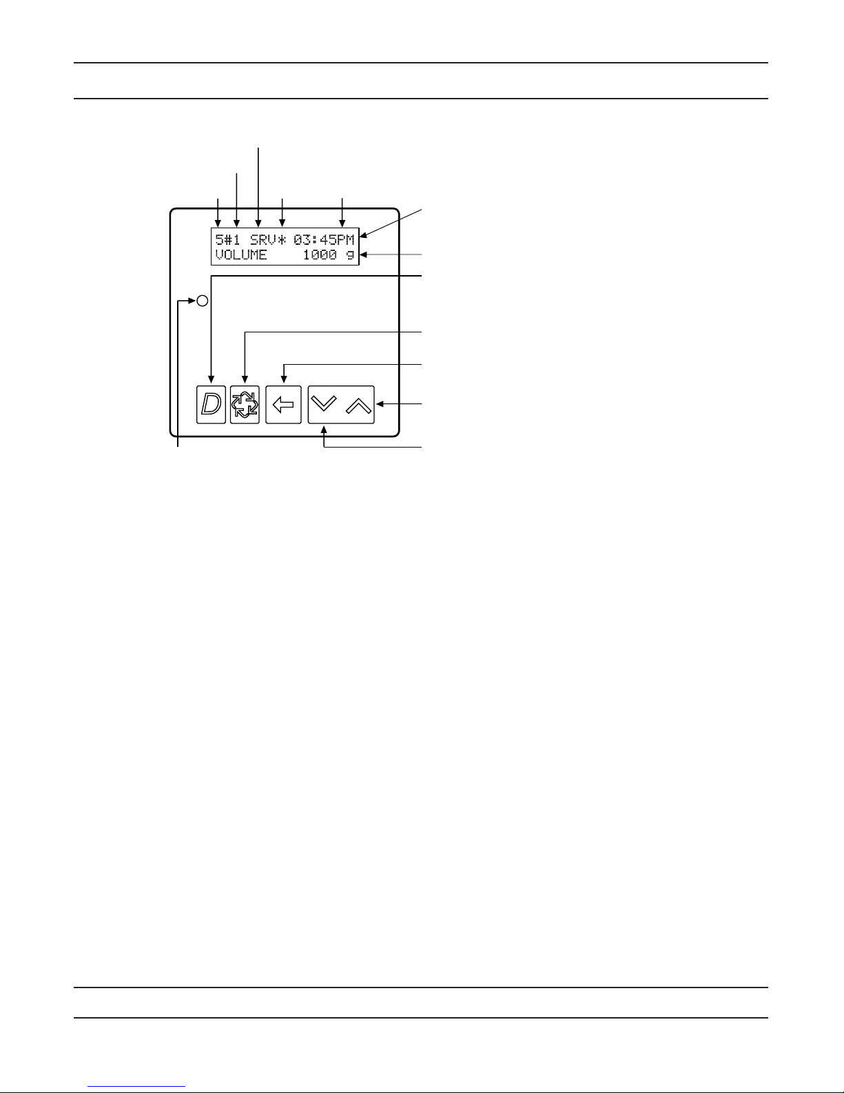
Timer Display Features
System
Number
Valve
Address
Valve State
(SBY, SRV, INI, CHG, LCK)
Flow
Indicator
Time
of Day Display Screen
Time of Day alternates with Error Screen
Example: Valve #, Volume Remaining,
Errors
Diagnostic Button
View Flow Rate, Peak Flow Rate, Totalizer, Hours
Between Last Two Regenerations, Hours Since Last
Regeneration, Adjustable Volume Remaining, Valve
Position, Send & Receive Errors, Software Version
Extra Cycle Button
Cycle Valve in Regeneration/Cycle Programming Steps
Shift Button
Adjusts Values to the Left
Up Button
Adjusts Values Up
Down Button
Adjusts Values Down
Volume Remaining
Status LED
Valve State:
CHG (Change of State)
CHG will be displayed when the lower drive changes from one state to another in dual piston valves.
INI (Initializing)
INI will display on the screen for 30 to 45 seconds when initializing after a power failure reset or programming.
RGQ (Regeneration Queued)
RGQ indicates that the reserve has been entered in a delayed system and regeneration has been queued.
When in the main screen, press the Extra Cycle button to toggle service (SRV) with RGQ.
Service (SRV)
SRV will display when the unit is in service.
LCK (Lock)
Lock will be displayed when the terminal/remote input block P4 on the circuit board is switched to “lock”.
See the “Network/Communication Cables & Connections” section of this manual.
LED Status Lights:
Blue LED:
Illuminates while the unit is in service and no errors exist. The unit will always be in service unless a
regeneration trigger has occurred (green LED light will be displayed).
A blinking blue light indicates the timer is in service, and queued for regeneration.
Green LED:
Illuminates when the unit is in Regeneration mode, unless an error condition exists.
A blinking green light indicates the timer is in standby, and not in regeneration.
Red LED:
Illuminates when there is an error.
Flow Indicator:
A rotating line (appearing as a rotating star shape) will display on the screen when ow is going through the
the meter.
Page 6
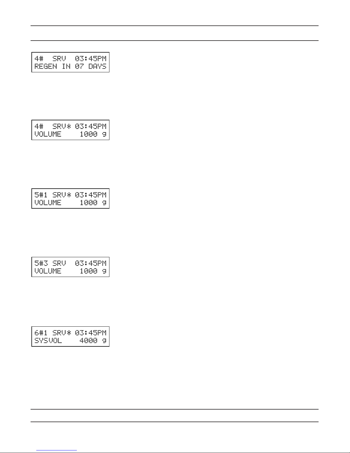
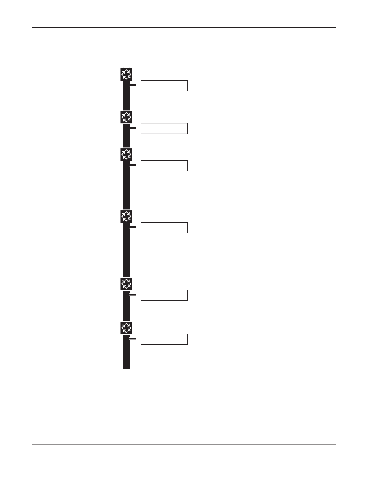
Timer Display - Screen Examples
Example:
In Service:
System 4 Time Clock
Example:
In Service:
System 4 Flow Meter Initiated 1.
or
System 4 Flow Meter Delayed2.
Example:
In Service:
System 5 Flow Meter Initiated (Lead Unit)1.
Example:
In Service:
System 5 Flow Meter Initiated (Lag Unit #3)1.
Example:
In Service:
System 6 Flow Meter Initiated (Lead Unit)1.
Page 7
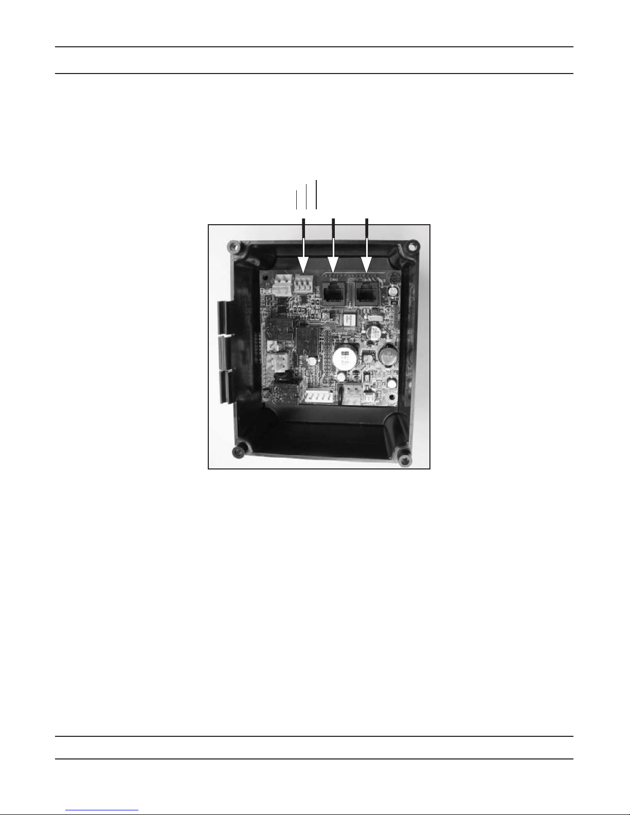
Network/Communication Cables & Connections
Use either a CAT3 or CAT5 Network/Communication cable.
1. Connect the network/communication cable rst before programming.
2. The maximum cable lenth between timers is 100 feet.
3. Connect each unit together from one communication port to the next communication port. It does not
matter which one goes to the next one.
Regen
Ground
1 2
Lock
3200NXT Circuit Board
The number of network/communication cables needed for setup is one less than the total number of valves.
Two-Unit System: One network/communication cable
Three-Unit System: Two network/communication cables
Four-Unit Systems: Three network/communication cables
Page 8
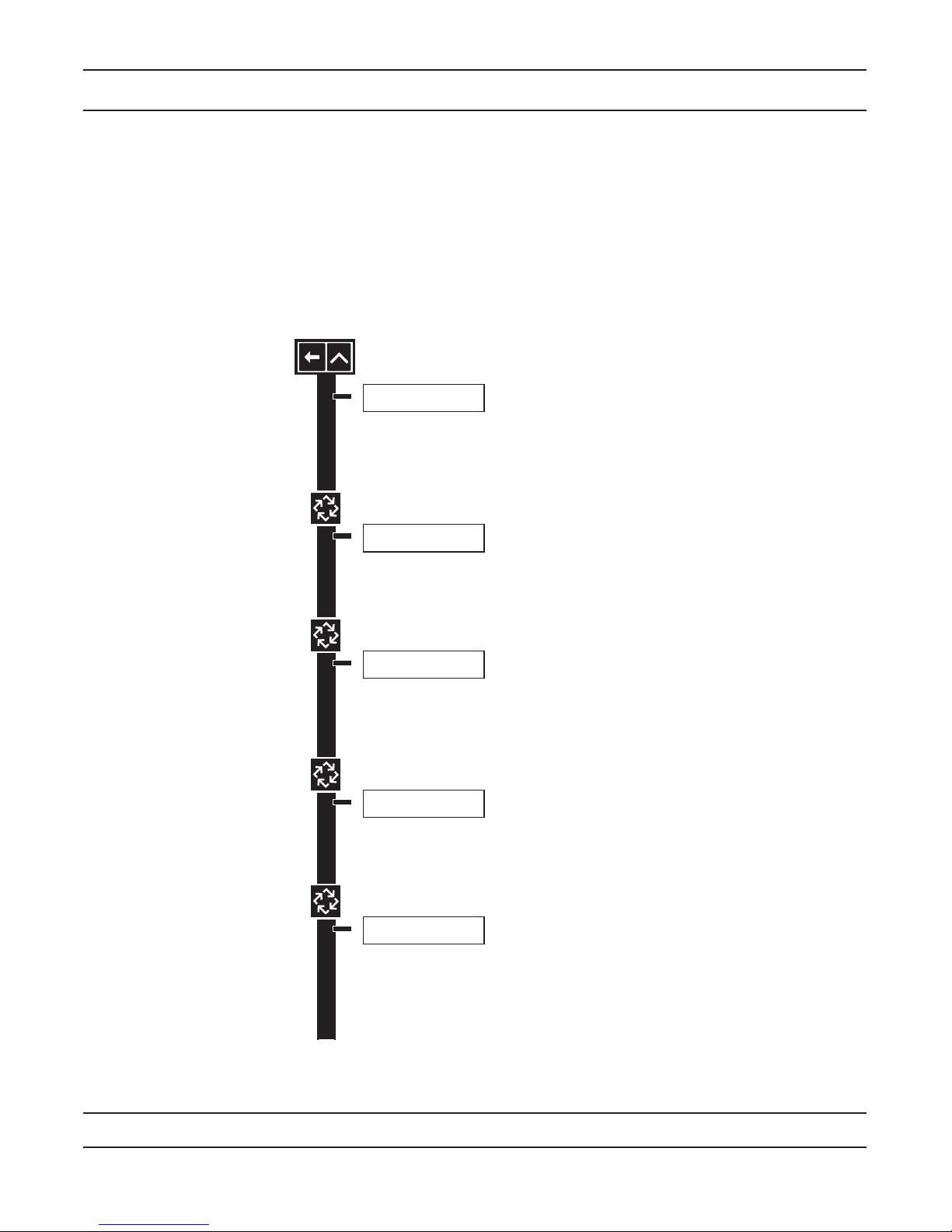
Master Programming Mode Flow Chart
SYSTEM TYPE: 4
SINGLE UNIT
Options: System 4 (single unit)
System 5 (2-4 units)
System 6 (2-4 units)
System 7 (2 units)
System 9 (2-4 units)
VALVE ADDRESS:
#2
Options: Valve Address #1 (First Control Valve)
Valve Address #2 (Second Control Valve) (Default)
Valve Address #3 (Third Control Valve)
Valve Address #4 (Fourth Control Valve)
Example:
System Type 4, Single Unit
Example:
Valve Address #2 (Second Control Valve) (Default)
SYSTEM SIZE:
2 VALVES
Options: 2 Valves in the System (Default)
3 Valves in the System
4 Valves in the System
Range: 2 to 4 Valves in the System
Example:
2 Valves in the System (Default)
REGEN TRIGGER:
TIME CLK DELAYED
Options: Time Clock Delayed (System 4 Only) (Default)
Meter Immediate (All System Types)
Meter Delayed Fixed Reserve (Systems 4 & 6 Only)
Remote Signal Start Immediate (All System Types)
Example:
Time Clock Delayed (Default)
VALVE TYPE:
2750
Options: 2750 (Default)
2850
2900
3150
3900
Stager - Butterfly
Stager - Notch Cam
Example:
2750 (Default)
NOTE: This screen will not display for
System Type 4.
NOTE: This screen will not display for
System Type 4.
NOTE: Depending on current option settings, some displays cannot be viewed or set.
Entering Master Programming Mode:
Press and hold the Shift and Up buttons for 5 seconds. 1.
Press the Extra Cycle button once per display until all displays are viewed and Normal Display is resumed.Option setting
displays may be changed as required by pressing either the Up or Down button. Use the Shift button to move one space
to the left.
2.
Depending on current valve programming, certain displays may not be viewed or set.
NOTE: If the “D” button is pressed while in master programming, no changes will be saved.
CAUTION: Before entering Master Programming, please contact your local professional water dealer.
Page 9
Valve Address #3 (Third Control Valve)
Valve Address #4 (Fourth Control Valve)
SYSTEM SIZE:
2 VALVES
Options: 2 Valves in the System (Default)
3 Valves in the System
4 Valves in the System
Range: 2 to 4 Valves in the System
Example:
2 Valves in the System (Default)
REGEN TRIGGER:
TIME CLK DELAYED
Options: Time Clock Delayed (System 4 Only) (Default)
Meter Immediate (All System Types)
Meter Delayed Fixed Reserve (Systems 4 & 6 Only)
Remote Signal Start Immediate (All System Types)
Example:
Time Clock Delayed (Default)
VALVE TYPE:
2750
Options: 2750 (Default)
2850
2900
3150
3900
Stager - Butterfly
Stager - Notch Cam
Example:
2750 (Default)
NOTE: This screen will not display for
System Type 4.
NOTE: This screen will only display on
the lead unit for System Types 6 & 7.
For all other System Types, it will display
for all units.
REGENERANT FLOW:
DOWNFLOW
Options: Downflow (Default)
UF Brine Draw
UF Fill First
Example:
Downflow (Default)
REMOTE SIGNAL
START: 00:06:00
Options: 00:06:00 (Default)
Range: 1 second to 99 minutes (1 hour, 39 minutes)
Example:
06:00:00 (Default)
(Hours:Minutes:Seconds)
DISPLAY FORMAT:
US-GALLONS
Options: U.S. - Gallons (Default)
European Units - Cubic Meters (Metric)
NOTE: In U.S. - Gallons mode, the display will be in 12-hour time.
NOTE: In European Units - Cubic Meters (Metric) mode, the display will
be in 24-hour time.
Example:
U.S. Gallons (Default)
UNIT CAPACITY:
00000000 GRAINS
Options: Grains (in U.S. Format) (Default)
Degrees (in Metric Format)
Range: 9,000 to 9,900,000 Grain Capacity in U.S. Format
90.0 to 190,000 Degree Capacity in Metric Format
NOTE: The word “GRAINS” will change to “DEGREES” in the metric
Display Format. Use the Shift button to move to the left.
Example:
Grains (Default)
CAPACITY SAFETY
FACTOR: 00%
Range: 0 to 50%
NOTE: Use the Shift button to move to the left.
Example:
00% (Default)
FEED WATER
HARDNESS: 15 GPG
Range: 1 to 199 Grains/Gallon (U.S. Format)
2 to 199 Degrees (Metric Format)
NOTE: Use the Shift button to move to the left.
Example:
15 GPG (U.S. Format) (Default)
Master Programming Mode Flow Chart
NOTE: Depending on current option settings, some displays cannot be viewed or set.
CAUTION: Before entering Master Programming, please contact your local professional water dealer.
Page 10

NOTE: This screen will only display on
the lead unit for System Types 6 & 7.
For all other System Types, it will display
for all units.
Options: Grains (in U.S. Format) (Default)
Degrees (in Metric Format)
Range: 9,000 to 9,900,000 Grain Capacity in U.S. Format
90.0 to 190,000 Degree Capacity in Metric Format
NOTE: The word “GRAINS” will change to “DEGREES” in the metric
Display Format. Use the Shift button to move to the left.
CAPACITY SAFETY
FACTOR: 00%
Range: 0 to 50%
NOTE: Use the Shift button to move to the left.
Example:
00% (Default)
FEED WATER
HARDNESS: 15 GPG
Range: 1 to 199 Grains/Gallon (U.S. Format)
2 to 199 Degrees (Metric Format)
NOTE: Use the Shift button to move to the left.
Example:
15 GPG (U.S. Format) (Default)
REGENERATION DAY
OVERRIDE:OFF
Example:
Off (Default)
REGENERATION DAY
OVERRIDE:01 DAYS
Options: Off (Default) or On
Range: 1 to 99 Days
Example:
1 Day
CYCLE 1 00:00:00
BACK WASH
Example:
Cycle 1 in Back Wash Mode
Options: Regeneration Cycle Step #1
Regeneration Cycle Step #2
Regeneration Cycle Step #3
Regeneration Cycle Step #4
Regeneration Cycle Step #5
NOTE: Please refer to the “Regenerant Flow Default Cycle Steps & Times”
in the Master Programming Mode section of the manual.
AUXILIARY RELAY:
DISABLED
Example:
Auxiliary Relay is Disabled
Options: Enabled
Disabled (Default)
CHEMICAL PUMP:
DISABLED
Example:
Chemical Pump is Disabled
Options: Enabled
Disabled (Default)
REGENERATION
TIME: 02:00AM
Example:
2:00 A.M. (Default)
Options: A.M. (U.S. Format)
HR (Metric Format)
NOTE: Regeneration time will not appear unless
Regeneration Day Override is on.
AUX RELAY OUTPUT
START 1 00:00:00
Example:
Auxiliary Relay Output in Start 1 at
0 hours, 0 minutes, & 0 seconds
Range: 00:00:00 to 18:00:00
AUX RELAY OUTPUT
END 1 00:00:00
Example:
Auxiliary Relay Output in End 1 at
0 hours, 0 minutes, & 0 seconds
Range: 00:00:00 to 18:00:00
NOTE: Only displayed if Auxiliary
Relay is enabled in previous screen.
Auxiliary Relay will only display if
Chemical Pump is OFF for System
Types 6 & 7.
NOTE: If Stager is chosen for Valve
Type, the Regeneration Cycle Step
description will not display.
NOTE: This screen will only display on
the lead unit for System Types 6 & 7.
For all other System Types, it will display
for all units.
Master Programming Mode Flow Chart
CAUTION: Before entering Master Programming, please contact your local professional water dealer.
Page 11
 Loading...