

Page 1
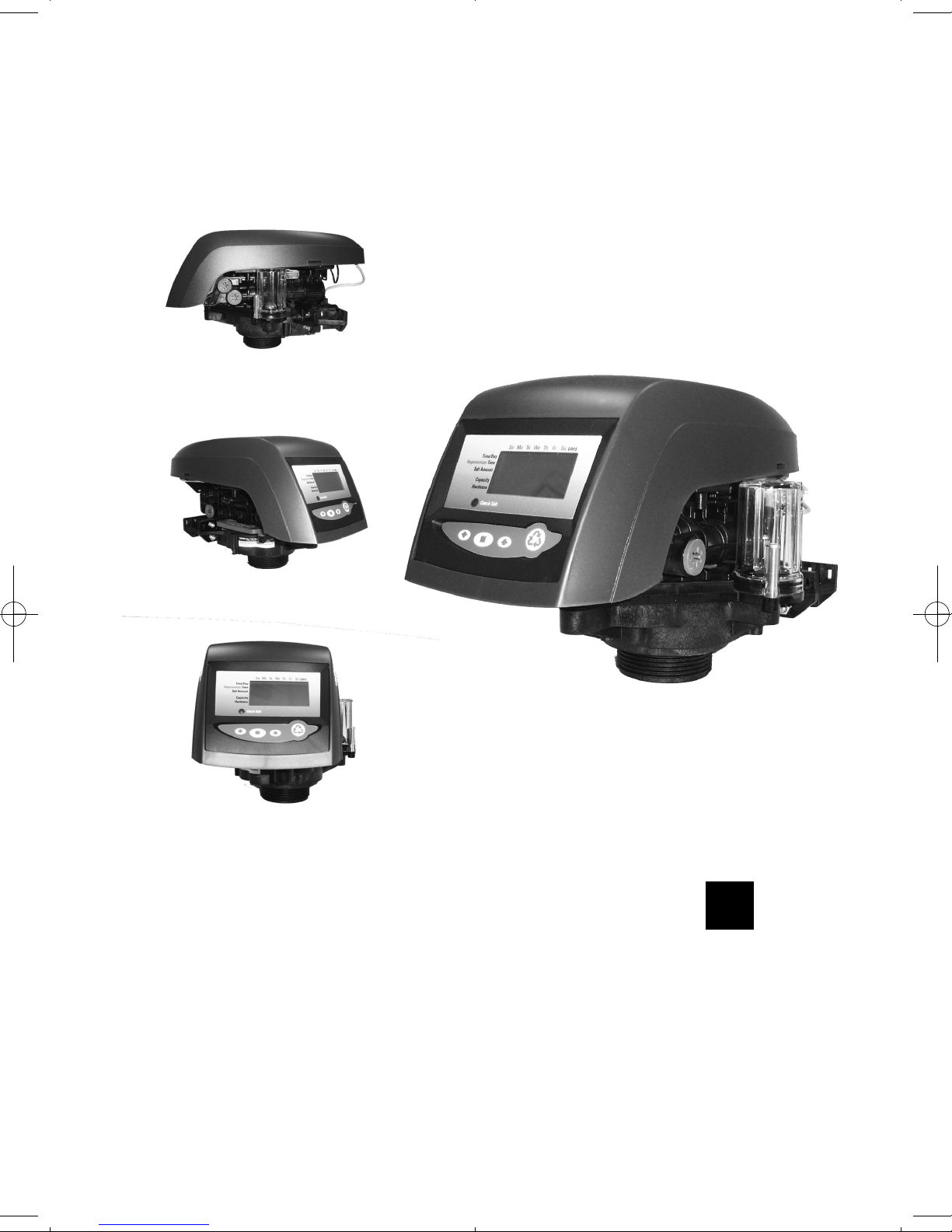
Operation Manual
Start up and Maintenance
Manuel d’utilisation
Mise en marche et Maintenance
Manual de Puesta en Marcha
Puesta en marcha y Mantenimiento
Steuerung Bedienungshandbuch
Inbetriebnahme und Wartung
2
24
46
70
225555 // LLOOGGIIXX 774400 -- 776600
De
Es
Fr
En
Page 2

Valve Features . . . . . . . . . . . . . . . . . . . . . . . . . . . . . . . . . . . . . . . . . . . . . 2
LCD Display . . . . . . . . . . . . . . . . . . . . . . . . . . . . . . . . . . . . . . . . . . . . . . 3
Installation . . . . . . . . . . . . . . . . . . . . . . . . . . . . . . . . . . . . . . . . . . . . . . 4
Location selection . . . . . . . . . . . . . . . . . . . . . . . . . . . . . . . . . . . . . 4
Water line connection . . . . . . . . . . . . . . . . . . . . . . . . . . . . . . . . . 4
Drain line connection . . . . . . . . . . . . . . . . . . . . . . . . . . . . . . . . . 5
Overflow line connection . . . . . . . . . . . . . . . . . . . . . . . . . . . . . . 6
Regenerant line connection . . . . . . . . . . . . . . . . . . . . . . . . . . . . . 6
Start-up of your softener . . . . . . . . . . . . . . . . . . . . . . . . . . . . . . . . 7
Step 1 - Program system size . . . . . . . . . . . . . . . . . . . . . . . . . . . . 7
Step 2 - Placing conditioner into operation . . . . . . . . . . . . . . . . . 7
Step 3 - Basic programming . . . . . . . . . . . . . . . . . . . . . . . . . . . . . 9
World LOGIX settings . . . . . . . . . . . . . . . . . . . . . . . . . . . . . . . . . 12
Step 4 - Capacity . . . . . . . . . . . . . . . . . . . . . . . . . . . . . . . . . . . . . 13
Step 5 - Hardness setting . . . . . . . . . . . . . . . . . . . . . . . . . . . . . . 13
Resetting the control to unprogrammed . . . . . . . . . . . . . . . . . . . . . . . 13
Manual regenerations . . . . . . . . . . . . . . . . . . . . . . . . . . . . . . . . . . . . . . 13
Options . . . . . . . . . . . . . . . . . . . . . . . . . . . . . . . . . . . . . . . . . . . . . . . . . 14
Flow diagrams . . . . . . . . . . . . . . . . . . . . . . . . . . . . . . . . . . . . . . . . . . . . . 16
Valve exploded view . . . . . . . . . . . . . . . . . . . . . . . . . . . . . . . . . . . . . . . 18
Nomenclature . . . . . . . . . . . . . . . . . . . . . . . . . . . . . . . . . . . . . . . . . . . . 19
SYNOPSIS
2
En
4
5
6
6
6
7
8
8
9
9
9
11
14
15
15
15
15
16
18
20
21
Page 3
3
En
Page 4
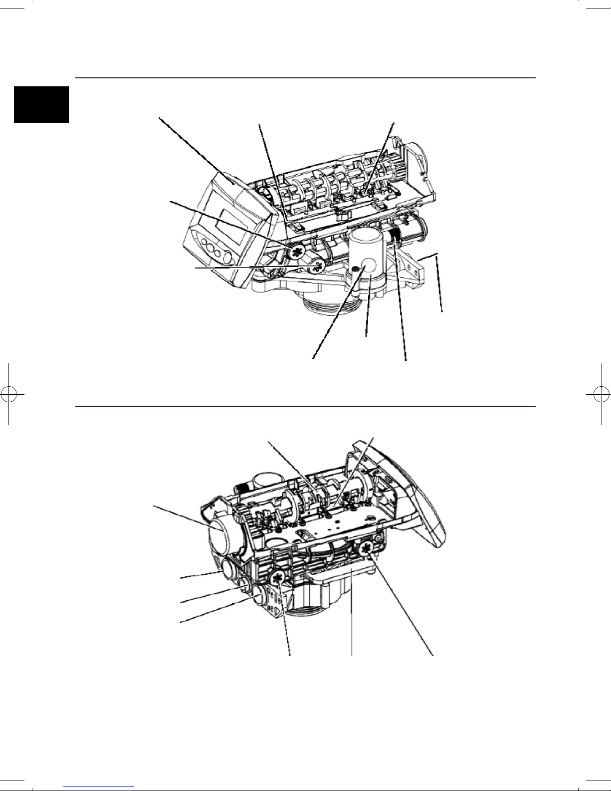
Complete Valve - Front view
Complete Valve - Back view
Control module
mount
Optical sensor
One piece valve
disc spring
Manifold
connection
Regenerant tank
tube connection
Aircheck
Check ball
Injector
and cap
Refill
Controller
Camshaft
Valve
discs
Injector
screen filter
Locking bar
Backwash
drain control
Inlet
Drain
Outlet
Motor
4
En
Page 5
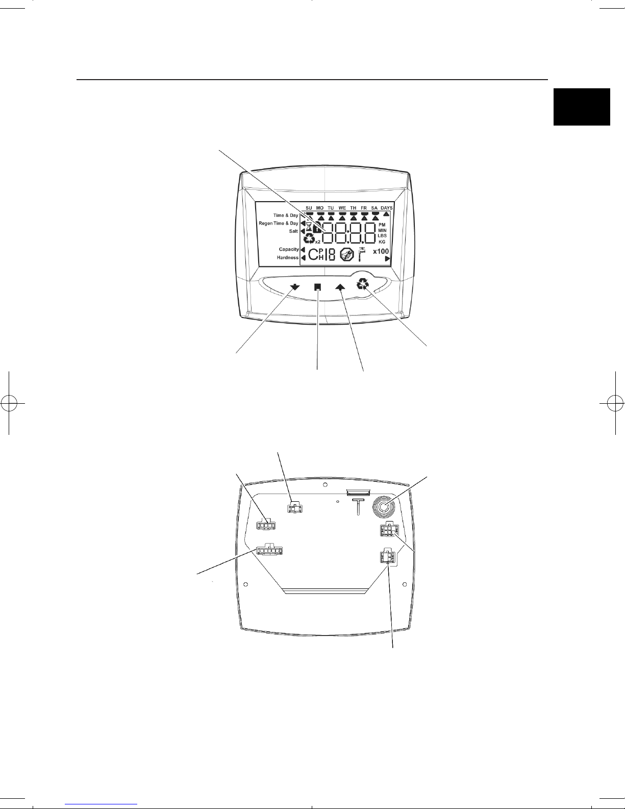
LCD Display
LCD Display
Manual regen
button
Down
button
Up
Button
Set
button
Secondary valve
motor control
(772 only)
Chlorine generator outlet
(EU and 742/762 versions only)
Lockout connection
(772 only)
AC adapter input
(low voltage)
Sensor input 716
by turbine 760/762
Dry contact signal input 740/742
5
En
Page 6
INSTALLATION
Location selection
Location of a water treatment system is important. The following conditions are required :
●
Level platform or floor.
●
Room to access equipment for maintenance and adding regenerant (salt) to tank.
●
Ambiant temperatures over 34°F (1°C) and below 120°F (49°C).
●
Water pressure below 120 psi (8.27 bar) and above 20 psi (1.4 bar).
●
Constant electrical supply to operate the controller.
●
Total minimum pipe run to water heater of ten feet (three meters) to prevent
backup of hot water into system.
●
Local drain for discharge as close as possible.
●
Water line connections with shutoff or bypass valves.
●
Must meet any local and state codes for site of installation.
●
Valve is designed for minor plumbing misalignments. Do not support weight of
system on the plumbing.
●
Be sur all soldered pipes are fully cooled before attaching plastic valve to the
plumbing.
Water line connection
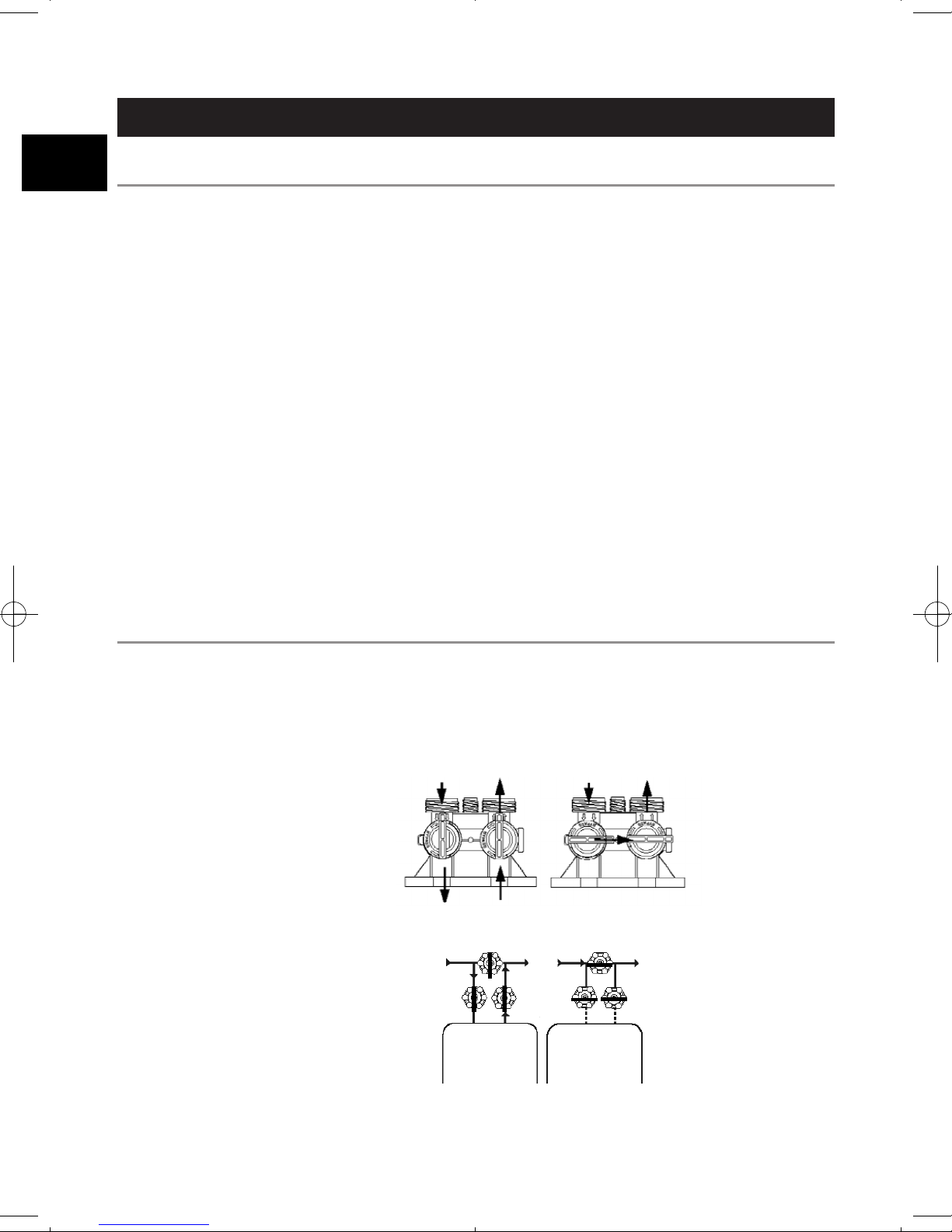
A by-pass valve system should be installed on all water conditioning systems.
Bypass valves isolate the conditioner from the water system and allow unconditioned
water to be used. Service or routine maintenance procedures may also require that
the system is bypassed. Figure 1 and 2 show the three common bypass methods.
Figure 1
256 By-pass for use
with 255 valve body.
Normal operation In by-pass
In Out OutIn
Figure 2
Typical globe valve
by-pass system
Normal
operation
Water
conditioner
Water
conditioner
In by-pass
6
En
Page 7
Drain line connection
1. If the backwash flow rate exceeds 5 gpm (22.7 Lpm) or if the unit is located
20-40 feet (6.1-12.2 m) from drain, use 3/4-inch (1.9 cm) tubing. Use appropriate
fittings to connect the 3/4-inch tubing to the 3/4-inch NPT drain connection on
valve.
2. The drain line may be elevated up to 6 feet (1.8 m) providing the run does not
exceed 15 feet (4.6m) and water pressure at the conditioner is not less than
40 psi (2.76 bar). Elevation can increase by 2 feet (61 cm) for each addditional
10 psi (0.69 bar) of water pressure at the drain connector.
3. Where the drain line is elevated but empties into a drain below the level of the
control valve, form a 7-inch (18 cm) loop at the far end of the line so that the
bottom of the loop is level with the drain line connection.This will provide an
adequate siphon trap.
Where the drain empties into an overhead sewer line, a sink-type trap must
be used.
Secure the end of the drain line to prevent it from moving.
NOTE : Standard commercial practices are expressed here. Local codes may
require changes to the following suggestions. Check with local authorities
before installing a system.
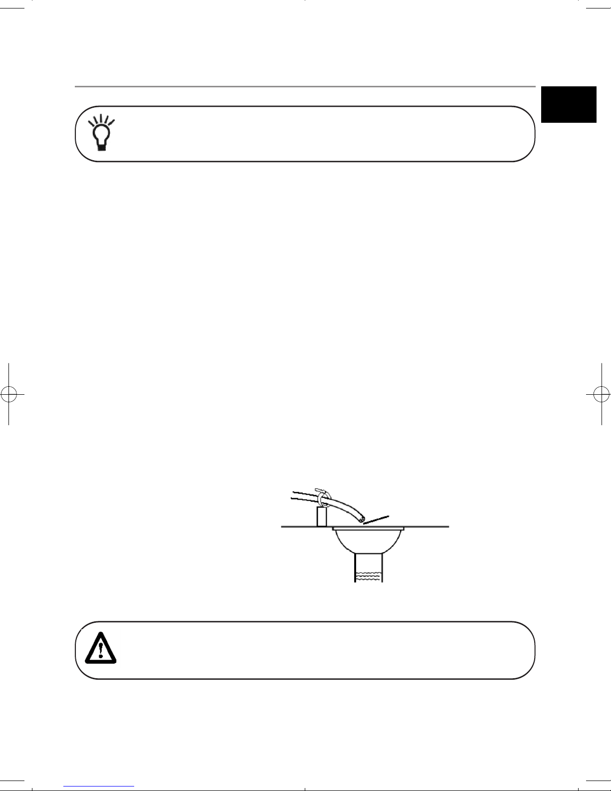
Figure 3
Drain line connection
drain
air gap
WARNING : Never insert drain line directly into a drain, sewer line or trap
(figure 3). Always allow an air gap between the drain line and the wastewater
to prevent the possibility of sewage being back-siphoned into the conditioner.
7
En
Page 8
Overflow line connection
In the event of a mal function, the regenerant tank overflow will direct “overflow”
to the drain instead of spilling on the floor.This fitting should be on the side of the
cabinet or regenerant tank. Most tank manufacturers include a post for the tank
overflow connector.
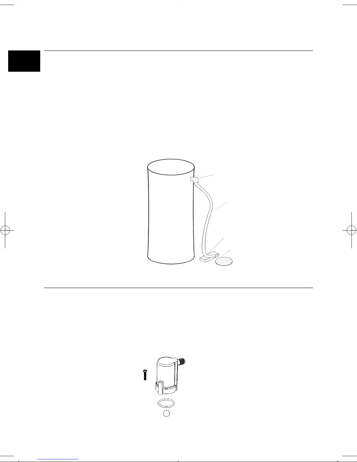
To connect the overflow line, locate hole on side of tank. Insert overflow fitting into
tank and tighten with plastic thumb nut and gasket as shown (figure 4). Attach
length of 1/2-inch (1.3 cm) I.D. tubing (not supplied) to fitting and run to drain.
Do not elevate overflow higher than overflow fitting.
Do not tie into drain line of control unit. Overflow line must be a direct, separate
line from overflow fitting to drain, sewer or tub.Allow an air gap as per drain line
instructions.
Regenerant line connection
The regenerant line from the tank connects to the valve. Make the connections and
hang tighten. Be sure that the regenerant line is secure and free from air leaks. Even
as small leak may cause the regenerant line to drain out, and the conditioner will
not draw regenerant from the tank. This may also introduce air into the valve
causing problems with the valve operation.
Figure 4
Figure 5
overflow fitting
drain tubing
secure hose in place
air gap
drain
regenerant line connection
8
En
Page 9
START-UP OF YOUR SOFTENER
Initial start-up step-by-step instructions
Preliminary check of hydraulic parameters of the valve
Step 1 - Program system size
This step may be performed by your system’s OEM manufacturer.
In this case, proceed to step 2.
●
Input system size - resine volume - in cubic feet or liters.
●
Use UP and DOWN buttons to scroll through resin volume
choices.
●
Choose the nearest volume to your actual system size.
●
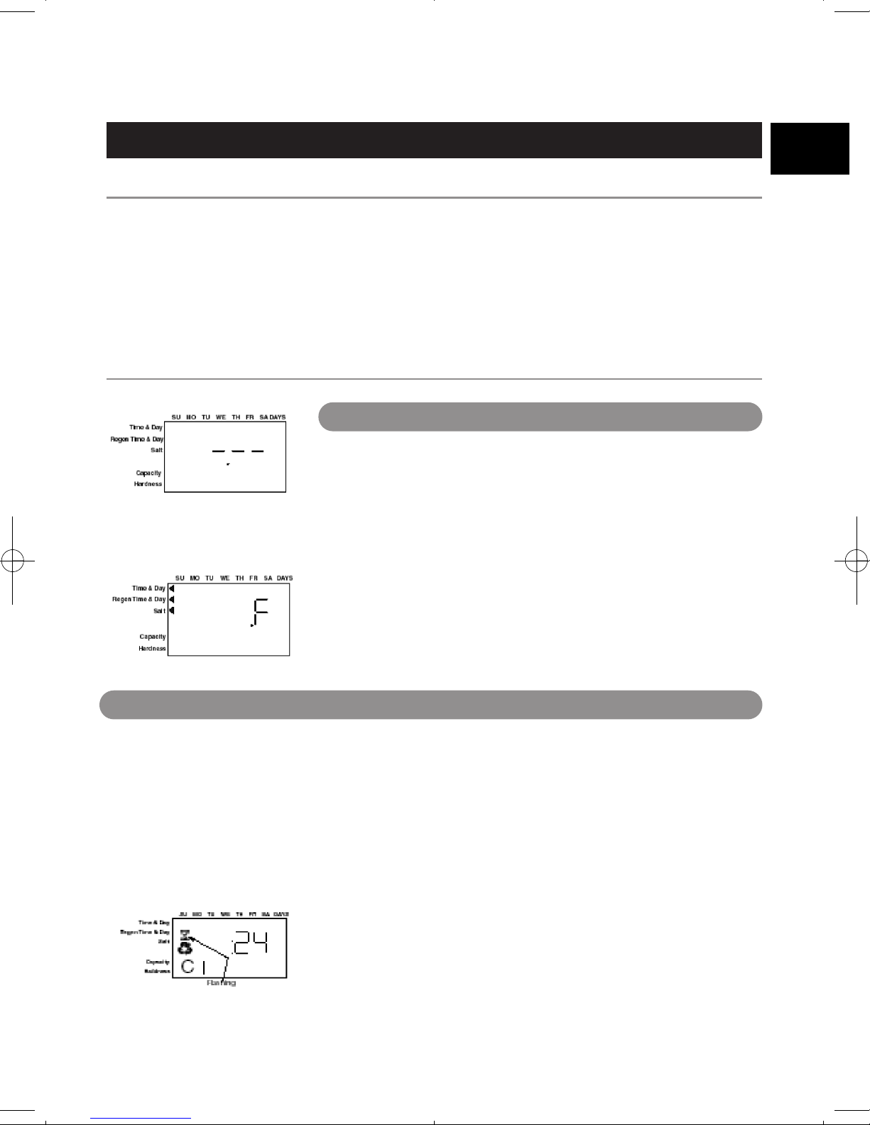
To choose a 3-cycle filter operation - press the DOWN button
until an “F” is displayed.
●
Press the SET button to accept the system size you’ve selected.
If incorrect setting is programmed, see “Resetting the control”
on page 15.
1. Remove the cover from the valve. Removing the cover will
allow you to see that the camshaft is turning, and in which
cycle the camshaft is currently positioned.
2. With the supply water for the system still turned off, position
the bypass valve to the “not in bypass” (normal operation)
position.
3. Hold the REGEN button on the controller down for
5 seconds.This will initiate a manual regeneration.
The controller will indicate that the motor is turning the
camshaft to the cycle C1 (backwash) position by flashing an
hourglass. The controller will display the total regen time
remaining.
If you press and hold the SET button, the controller will
indicate the time remaining in the current cycle.
Step 2 - Placing conditioner into operation (conditioner start-up)
After you have performed the previous initial power-up steps, you will need to place the
conditioner into operation. Follow these steps carefully, as they differ from previous
Autotrol valve instructions.
This step must have been done by your OEM. You need to check that there is no mistake. In
fact, every setting stored in the electronic is largely dependant of hydraulic parameters
(injector/backwash) installed on the valve.
Please check that you are using the correct injector and backwash control in accordance with
the used pressure tank (see table page 14).
9
En
Page 10
4. Fill the media tank with water.
A. While the controller is in cycle C1 (backwash), open the water supply valve very slowly to
approximately the 1/4 open position.
B. When all of the air has been purged from the media tank (water begins to flow steadily from
the drainline), open the main supply valve all of the way. This will purge the final air from the tank.
C. Allow water to run to drain until the water runs clear from the drain line. This purges any
refuse from the media bed.
D. Turn off the water supply and let the system stand for about five minutes.This will allow for
any air trapped to escape from the tank.
5. Add water to the regenerant tank (initial fill) - Conditioner only.
A. With a bucket or hose, add approximately 4 gallons (15 liters) of water to the regenerant tank.
B. If the tank has a salt platform in the bottom of the tank, add water until the water level is
approximately 1 inch (25 mm) above the platform.
6. Engage the refill cycle to prime the line between the regenerant tank and the valve
Conditioner only.
A. Slowly open the main water supply valve again, to the fully open position. Be sure not to open
too rapidly as that would push the media out the media tank.
B. Advance the controller to the refill position. From cycle C1 (backwash), press and hold the SET
button. This will display the current cycle.
While pressing the SET button, press the UP arrow to advance to the next cycle. Continue
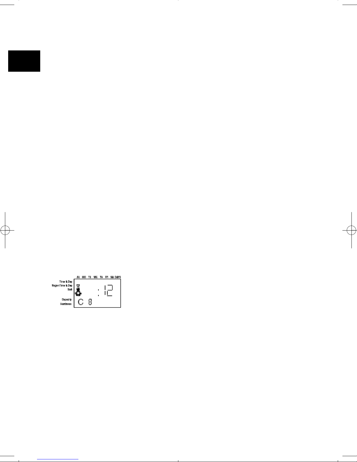
to advance through each cycle until you have reached cycle C8 (refill).
C. With the water supply completely open, when you arrive at
cycle C8 (refill), the controller will direct water down through
the line to the regenerant tank. Let the water flow through the
line until all air bubbles have been purged from the line.
D. Do not let the water flow down the line to the tank for more
than one to two minutes, or the tank may overfill.
E. Once the air is purged from the line, press the SET button and
the UP button simultaneously to advance to cycle C0 (treated
water) position.
7. Draw water from the regenerant tank.
A. From the treated water position (cycle C0), advance the valve to the draw regenerant
position. Hold the REGEN button down for five seconds.
The controller will begin a manual regen, and advance the control valve to the cycle C1
(backwash). Press the SET and UP buttons to advance to cycle C2 (draw).
B. With the controller in this position, check to see that the water in the regenerant tank is being
drawn out of the tank. The water level in the tank should recede very slowly.
10
En
Page 11
C. Observe the water being drawn from the regenerant tank for at least three minutes. If the
water level does not recede, or goes up, reference the Troubleshooting section.
8. If the water level is receding from the regenerant tank you can then advance the controller back
to the treated water (C0) position by pressing SET and UP buttons simultaneously to advance
the controller to the C0 position.
9. Finally, turn on a faucet plumbed after the water conditioner. Run the faucet until the water runs
clear.
NOTE : If a button is not pushed for thirty seconds, the controller returns
to normal operation mode. Pushing the regenerate button immediately
returns the controller to normal operation.
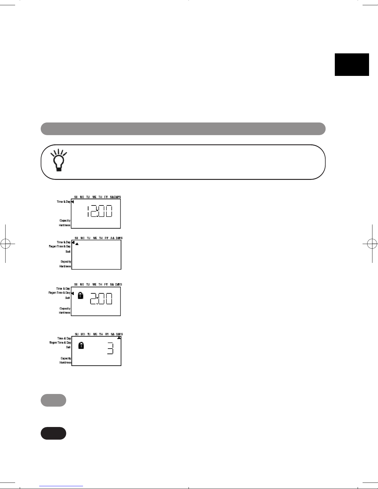
●
Time of day
When the time of the day is displayed, push SET. The time will
flash. Use the arrows buttons to increase/decrease the time.
Push SET to enter the selection.
●
Day of the week
The day of the week does not have a default setting. It is entered
at power-up.To change the current day, push SET when day of
week is displayed.A flag will flash beneath the current day. Use
the arrow buttons to change. Push SET to enter the selection.
●
Time of regeneration
This is set for 2:00 AM as the default.The controller does not
account for daylight savings time.
To change this setting, push SET. Use the arrow buttons to
increase/decrease the time. Push SET to enter the selection.
●
Number of days between regeneration
The controller can be programmed to regenerate automatically
from a 1/2 (.5) day to a 99 day frequency.
The 1/2 day regeneration mode will regenerate at the “time of
regeneration”, as well as 12 hours opposite from that time. For
example, the controller will regenerate at 2 AM and at 2 PM on
the same day.
Step 3 - 740/760 Basic Programming
The default setting is three days for the 740. To change, push SET when this setting is
displayed. Use the arrow buttons to increase/decrease. Push SET to enter the selection.
740
The default setting is 0 days for the 760. To change, push SET when this setting is
displayed. Use the arrow buttons to increase/decrease. Push SET to enter the selection.
760
11
En
Page 12
●
Specific day of week regeneration (740 only)
To change the controller to regenerate on specific days,set the number of days between
regeneration to zero.
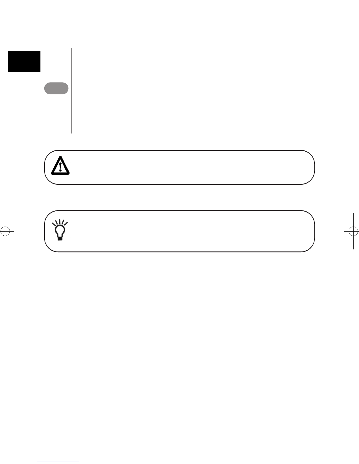
After this has been completed, the arrow on the left side of the display will be pointing
to regeneration time/day. Press the SET button and the display will show a flashing
cursor at the top under Sunday. The day of week can be selected when the cursor is
below it.
To toggle the day on/off, the triangular cursor must be below that day and flashing.
The UP or DOWN buttons are used to turn the days flag on/off. If the cursor is in
position but steady on, use the UP or DOWN buttons.
To move the cursor when it is flashing push the SET button once. This will move the
cursor one position to the right and change the status to steady on.
NOTE : Regeneration on specific day is used to provide regeneration when
water demands are not steady. Example : if the weekdays have low usage and
the weekend is high, then regeneration every three days will not meet the
requirements.
WARNING : Setting days between regeneration to zero will cause the
system to not regenerate. This setting is used for selecting regeneration on
specific days or to use with a remote regeneration input. See below.
740
12
En
Page 13
The Logix series controllers are set-up to automatically calculate
the capacity of the system by multiplying the resin/media volume
that was entered earlier into the controller, with the regenerant
amount entered by the dealer/installer. This eliminates the need
for salting efficiency tables.
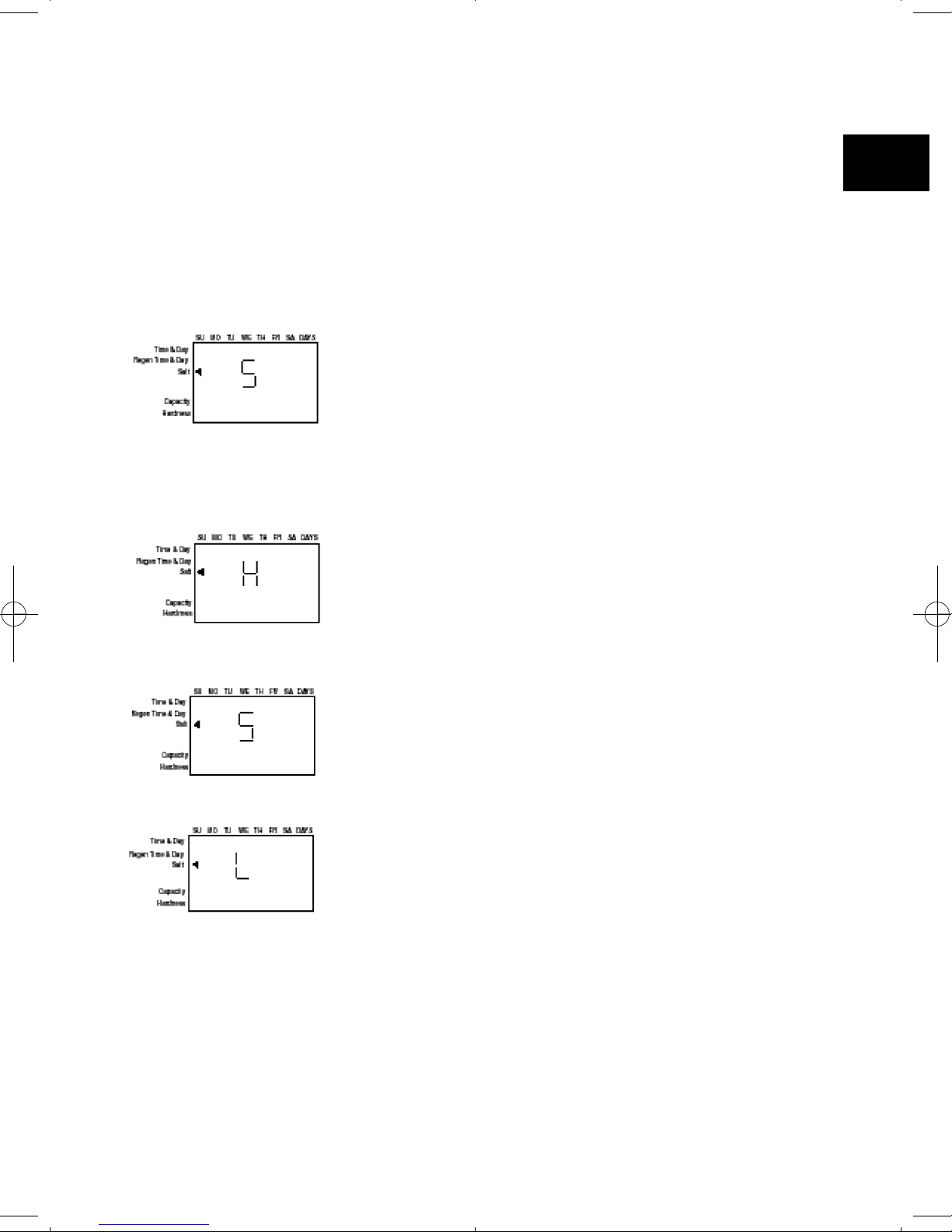
The default setting is “S” (Standard salt)
To enable the most simple programming possible on the 740
controllers, the dealer/installer has three salt amount options to
choose from. These are set up to give the installation the maximum performance based on the inputs by the dealer/installer.
The three salting options are :
High salt This setting gives the installation the highest
capacity possible for that resin volume. This is a
great setting for applications with very high
hardness, many occupants or for applications
where the dealer wants to always ensure that the
application has soft water. This setting may tend
to use less water over the course of a year, because
it generally needs to be regenerated less often.
This setting is displayed as an “H”.
Standard salt This is the default setting for the controller. This
setting fits most applications around the word. It
gives you an efficient use of salt, while maintaining
a large enough capacity to regenerate every three
days for most applications.
This setting is displayed as an “S”.
Low salt This setting is provided to give your installation
the maximum efficiency of salt usage, as measured
in grains of hardness softened per pound of salt
used (grams of CaCO
3
removed per kilogram of
salt used). This setting is useful for markets where
highy efficient conditioners are expected or required
by the consumers or law.
This setting is displayed as an “L”.
●
Amount of regenerant used per regeneration
If the installation is a 3-cycle filter, skip to Filter Backwash Time. The amount of regenerant does not
apply.
13
En
Page 14
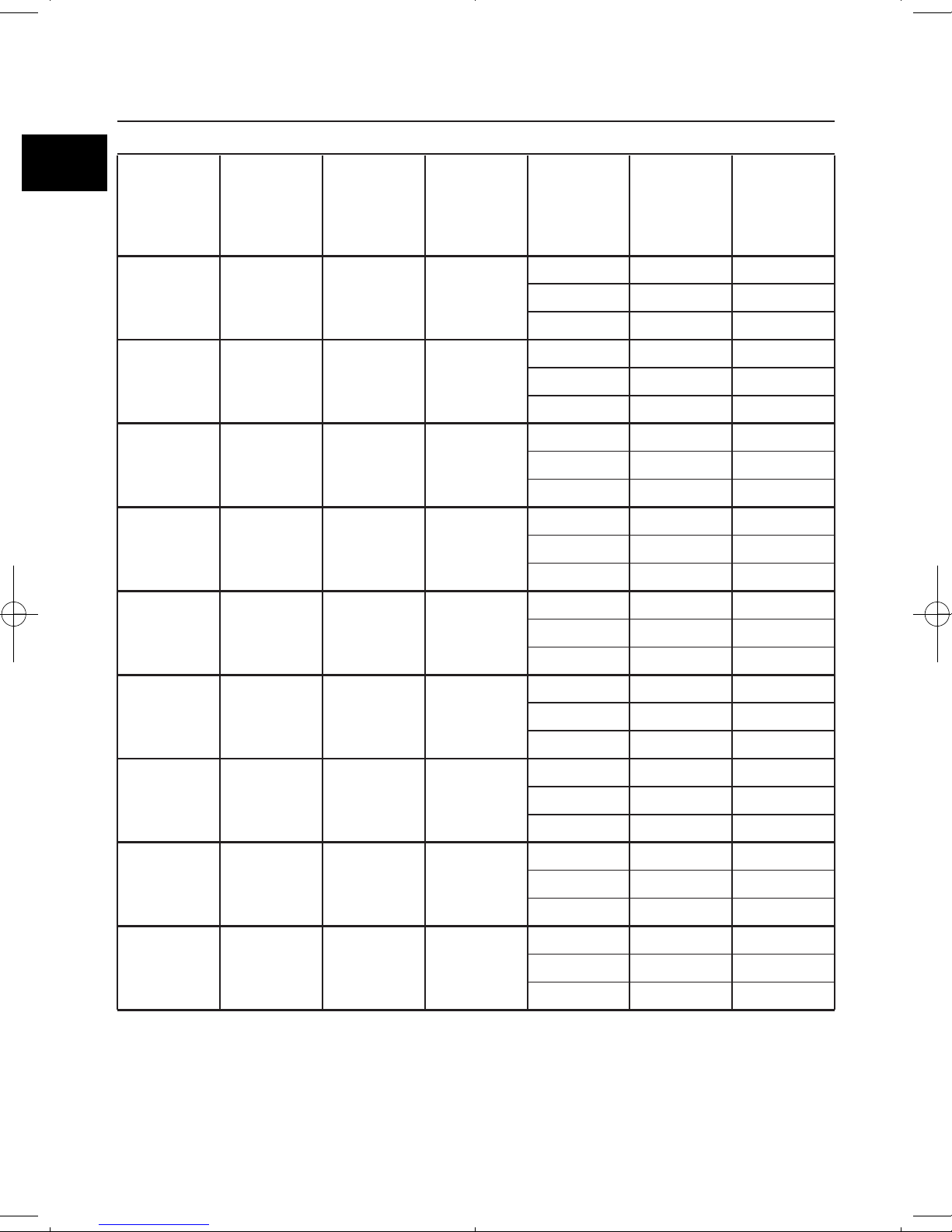
World Logix Settings
L
S
H
0,2
0,45
0,91
0,1
0,2
0,3
0,45
0,91
1,81
0,68
2,04
3,40
1,13
3,17
4,98
1,58
4,08
6,80
1,80
4,99
8,62
2,27
6,12
10,20
2,94
8,16
13,61
4,53
12,25
20,41
0,3
0,4
0,5
0,4
0,8
1,0
0,7
1,2
1,5
1,0
1,6
2,0
1,2
2,1
2,5
1,5
2,5
3,0
2,0
3,2
3,9
3,0
4,9
5,8
L
S
H
L
S
H
L
S
H
L
S
H
L
S
H
L
S
H
L
S
H
L
S
H
Salt
Setting
Media
Volume
(liters)
Inj.
Max
Height
Ta n k
Volume
(liters)
Total Salt
Amount per
regeneration
(kgs)
Estimated
capacity
(kg)
5
10
15
20
30
35
40
50
80
E
yellow
E
yellow
F
peach
G
tan
H
Lt purple
J
Lt blue
K
pink
L
orange
L
orange
18
35
44
44
48
54
54
54
65
6
6
7
8
9
10
12
13
14
H = High salt - approximately 15 lbs. per cu. ft. of media
S = Standard salt - approximately 9 lbs. per cu. ft. of media
L = Low salt - approximately 3.3 lbs. per cu. ft. of media
14
En
Page 15
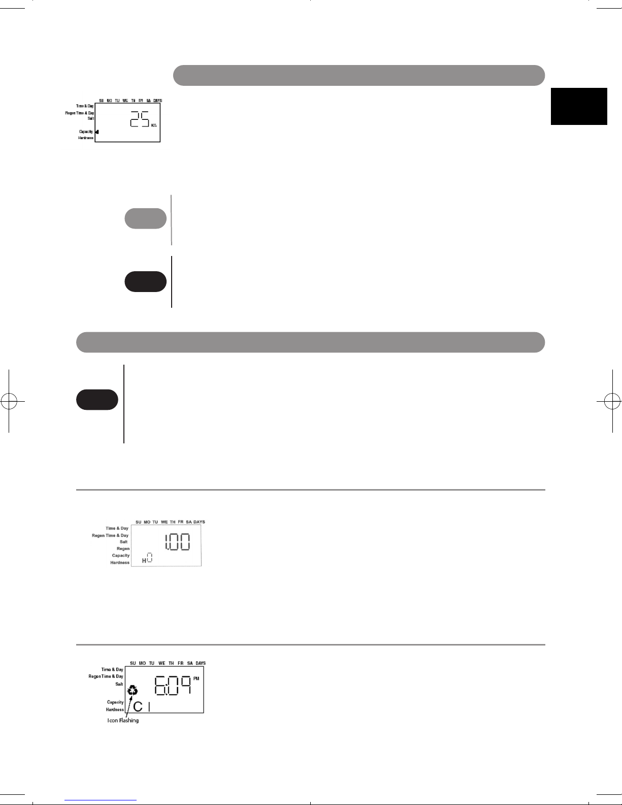
Step 4 - Capacity
The 740 controller is designed to estimate capacity of the system by multiplying the
initial resin/media volume by the regenerant amount programmed in under “Amount of
regenerant used per regeneration”. An estimated total system capacity is displayed in
kilograins (kilograms CaCO
3
) that can be removed by the fully regenerated media bed.
This value is derived by standard water treatment industry norms. The system
capacity is displayed merely for the installers reference when determining regeneration
frequency. This value is displayed, but cannot be directly changed of the 740 time clock
controller.
●
Capacity is only displayed for information purposes on 740 control.
It does not (and cannot) need to be changed. If using 740 control,
programming is complete, the control will return you to the normal
operation mode
●
To change capacity on 760 control, presse the SET button to make default
capacity flash. Use the UP and DOWN buttons to increment to the
desired capacity. Presse the SET button to accept the setting and advance
to next parameter.
760
760
740
Resetting the control to unprogrammed
The control can be returned to its unprogrammed state. To erasse
all information that was programmed in :
1. Press the DOWN arrow and the SET button for five seconds.
2. Press and hold the SET button for five seconds.
3. The display will show three dashes and a decimal point.
4. The display will be flashing.
The display indicates all programming has been erased.
For a delayed regeneration (at the next set time of regeneration)
●
Push the REGEN button once. The recycle symbol will be
flashing on the display. Push the REGEN button again to cancel.
Manual regeneration
Step 5 - Hardness setting (
760 only)
The hardness setting is set in grains per gallon (ppm CaCO3).
The hardness is divided into the total capacity setting,giving a total volume of water that
can be conditioned before a regeneration is needed.
To set, press SET when P8 is displayed,and use the UP or DOWN buttons to increment.
Press SET again to accept the setting.
15
En
Page 16
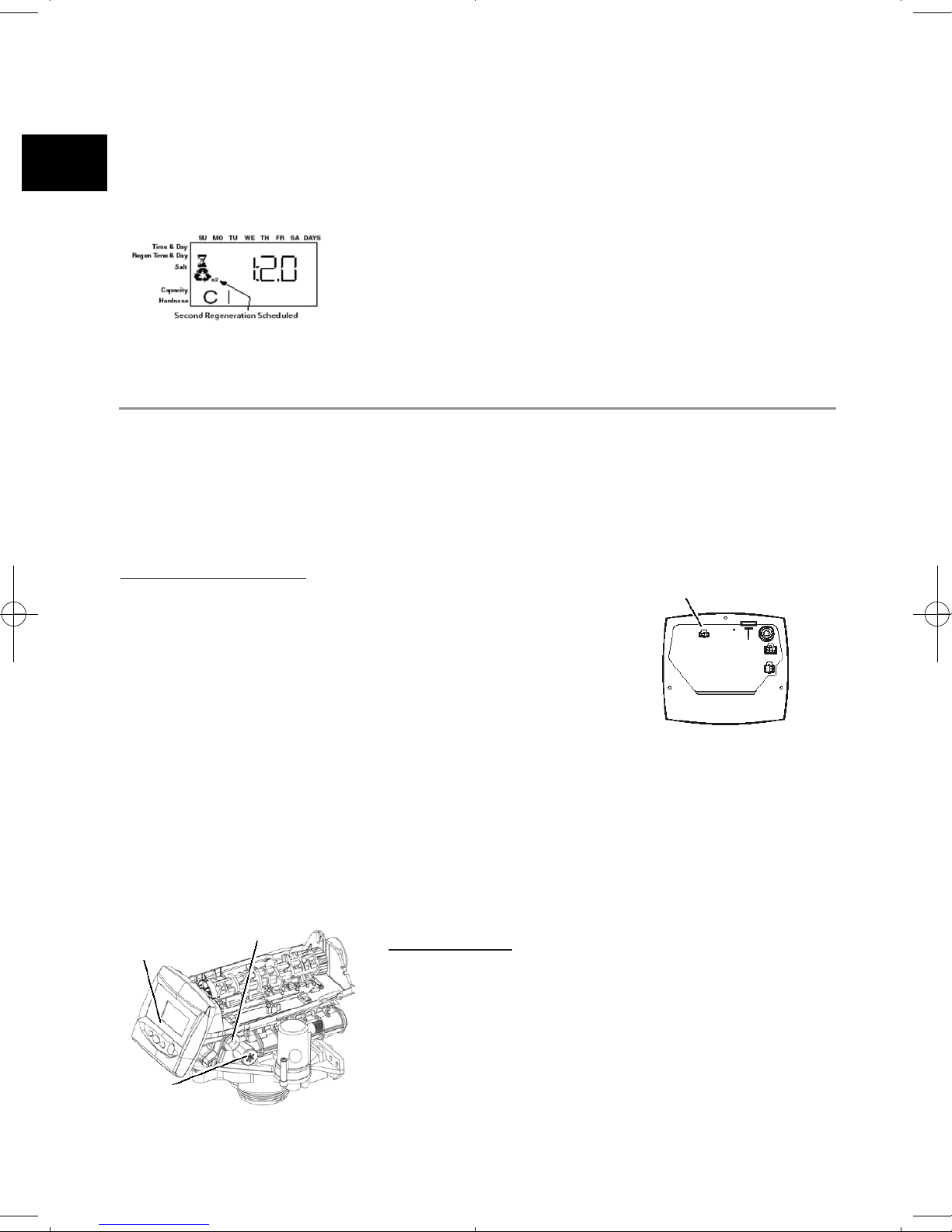
For an immediate, double regeneration :
●
After an immediate manual regeneration has begun, and the
camshaft has rotated to cycle C1, you can initiate a second
immediate manual regeneration.
●
Press and hold the REGEN button for 5 seconds once the
camshaft has begun cycle C1.
●
The display will show a x2 icon indicating that a second
manual regeneration will occur after the current regeneration
is completed.
For an immediate regeneration :
●
Push and hold the REGEN button for five seconds. The display will show the regeneration symbol.
The camshaft will start rotating to cycle C1.
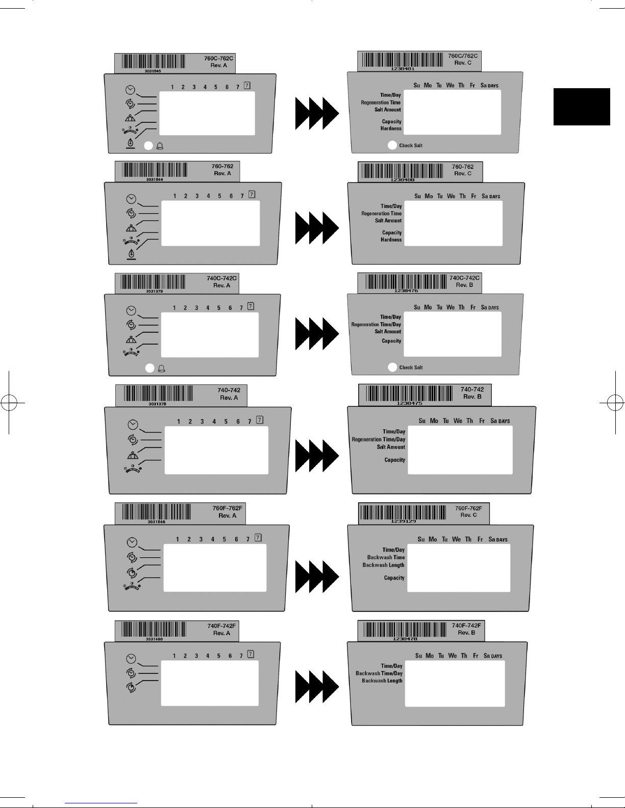
Logix Chlorine Generator (Check Salt Light)
The Logix 740C/742 and 760C/762 controls have the capability to produce a low level of chlorine
to chlorinate the resin bed during regeneration. Included with the chlorine generator is the check
salt light which indicates when the end user needs to add salt to the regenerant tank. Potassium chloride or sodium chloride may be used. Installing the chlorine generator is simple.
Installation instructions
●
STEP 1 - Remove the Logix control from the valve and dis-
connect power.
●
STEP 2 - Insert the small chlorine generator connector and
wire to the back of the Logix control at the connection labled
“Chlorine Generator Outlet 740C/742 and 760C/742”. Logix
control removal procedure can be found in the Logix technical
manual.
●
STEP 3 - Remove the existing refill controler and ball from the
valve and replace it with the chlorine generator refill flow control.
See the illustrations to the left for the location of the refill controler.
●
STEP 4 - Insert the small chlorine generator connector and wire to the back of the Logix control
at the connection labled “Chlorine Generator Outlet 740C/742 and 760C/742”. Logix control
removal procedure can be found in the Logix technical manual.
●
STEP 5 - Reconnect power to the logix control and reinstall the control to the valve
Programmation
No programming is necessary for the chlorine generator to
work properly on the 740C/760C. After the chlorine generator senses regenerant for the first time it will be functional.
There is a check salt light on the front of the Logix control
that will illuminate when there is no regenerant present during
the regenerant draw.
OPTIONS
Chlorine Generator Outlet
(740C/742 and 760C/742 versions only)
Back on Logix Control
Refill controler
Check Salt Light
Injector and Cap
16
En
Page 17
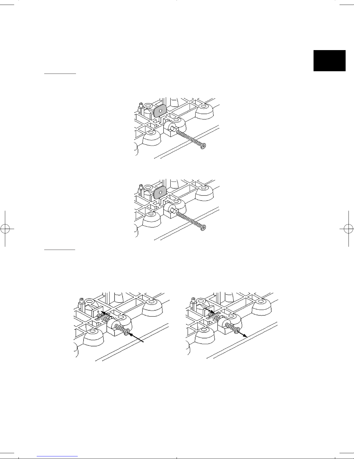
255 Blending Valve Kit
Kit (P/N 1239760) for the 255/700 series includes :
- Nut (10-32) and Adjusting scew
Installation
Insert the nut into the Blending Valve orifice located near the Bypass Flapper shown below.
Insert the screw through the top plate and then through the nut (Figure A).
Tighten the screw until it touches the Bypass Flapper (Fig. B).
Operation
Tightening the adjusting screw will force the Bypass Flapper open. The open Flapper will
allow untreated (hard) water to blend with the treated water supply. As the adjusting
screw is turned in, the hardness of the oulet water increases (Fig. C).
Loosening the adjusting screw will allow the Bypass Flapper to close. The closing action
will blend less untreated water into the oulet flow.
To blend a specific amount of hardness into outflow, adjust the screw and test the water.
Repeat the procedure as needed until the desired hardness level is reached.
Figure A
Figure B
Figure C Figure D
17
En
Page 18
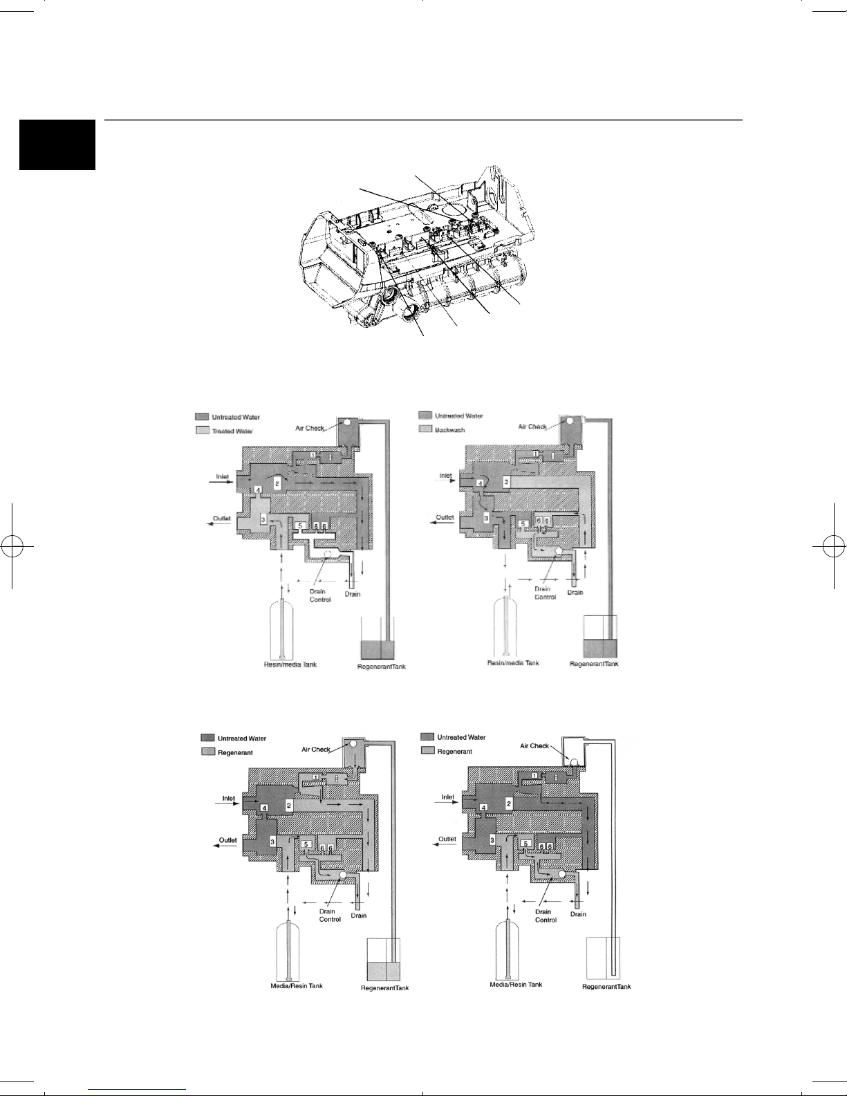
Flow Diagram
Backwash/Drain (6)
Rinse Drain (5)
Bypass (4)
Outlet (3)
Regenerant (1)
Inlet (2)
C0 Treated water position
(normal position)
C1 Backwash 1 position
C2 Draw position C3 Slow Rinse position
Valve Nr
1 - Closed
2 - Opened
3 - Opened
4 - Closed
5 - Closed
6 - Closed
Valve Nr
1 - Closed
2 - Closed
3 - Opened
4 - Opened
5 - Closed
6 - Opened
Valve Nr
1 - Opened
2 - Closed
3 - Closed
4 - Opened
5 - Opened
6 - Closed
Valve Nr
1 - Opened
2 - Closed
3 - Closed
4 - Opened
5 - Opened
6 - Closed
18
En
Page 19
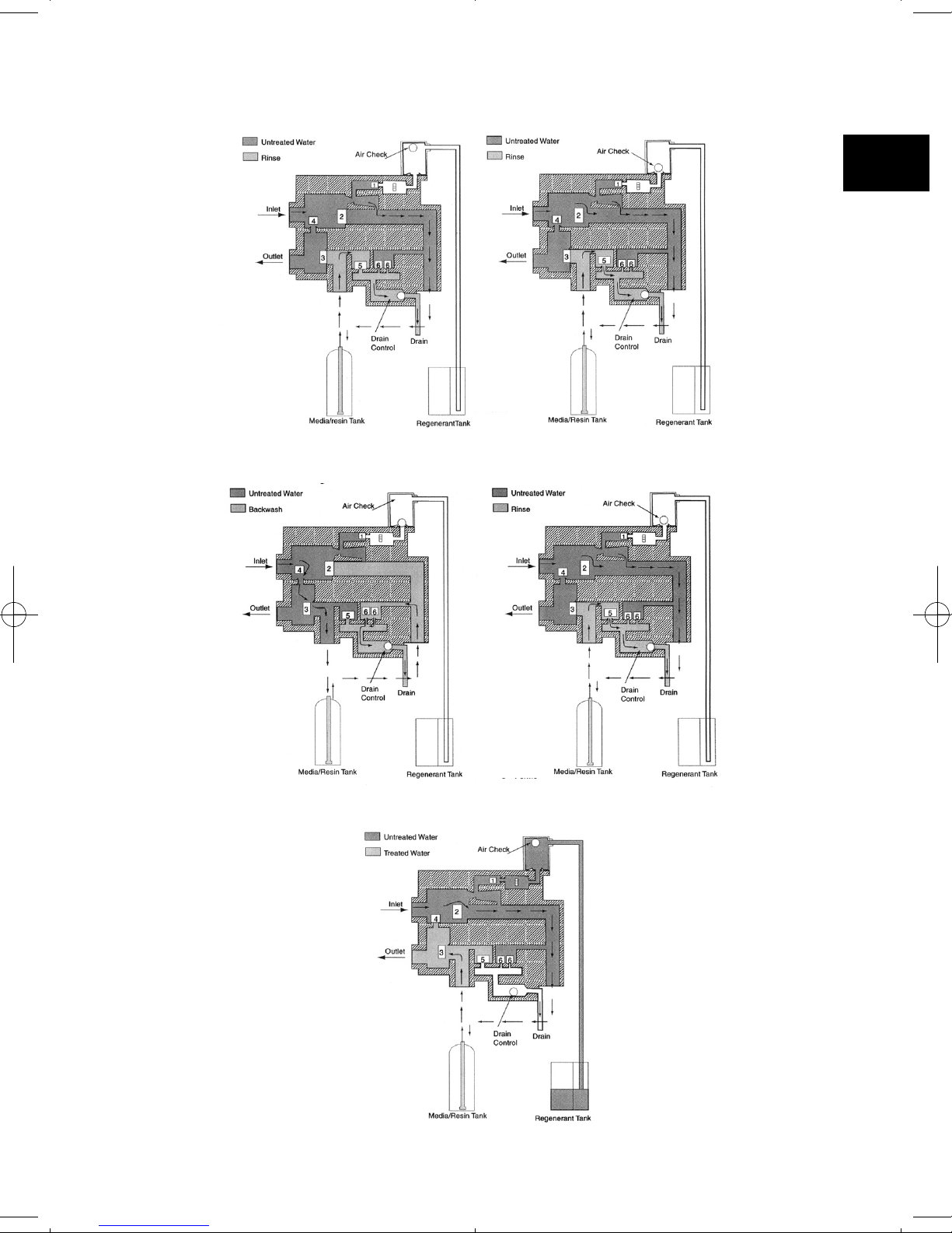
C4 System Pause position
(repressurize)
C5 Fast Rinse 1 position
C6 Backwash 2 position C7 Fast Rinse 2 position
C8 Refill
Valve Nr
1 - Closed
2 - Closed
3 - Closed
4 - Opened
5 - Closed
6 - Closed
Valve Nr
1 - Closed
2 - Opened
3 - Closed
4 - Opened
5 - Opened
6 - Closed
Valve Nr
1 - Closed
2 - Closed
3 - Opened
4 - Opened
5 - Closed
6 - Opened
Valve Nr
1 - Closed
2 - Opened
3 - Closed
4 - Opened
5 - Opened
6 - Closed
Valve Nr
1 - Opened
2 - Opened
3 - Opened
4 - Closed
5 - Closed
6 - Closed
19
En
Page 20
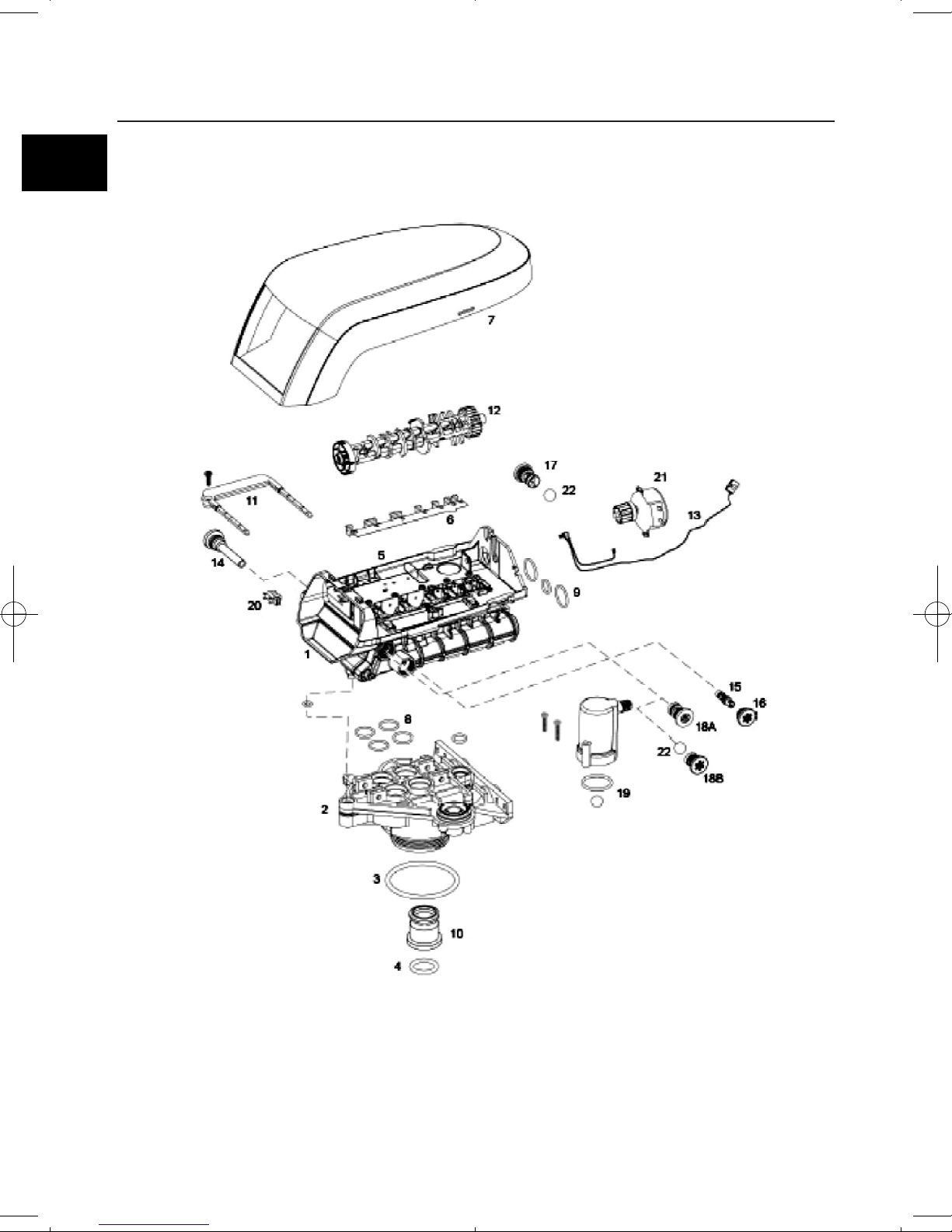
255 VALVE EXPLODED VIEW
20
En
Page 21
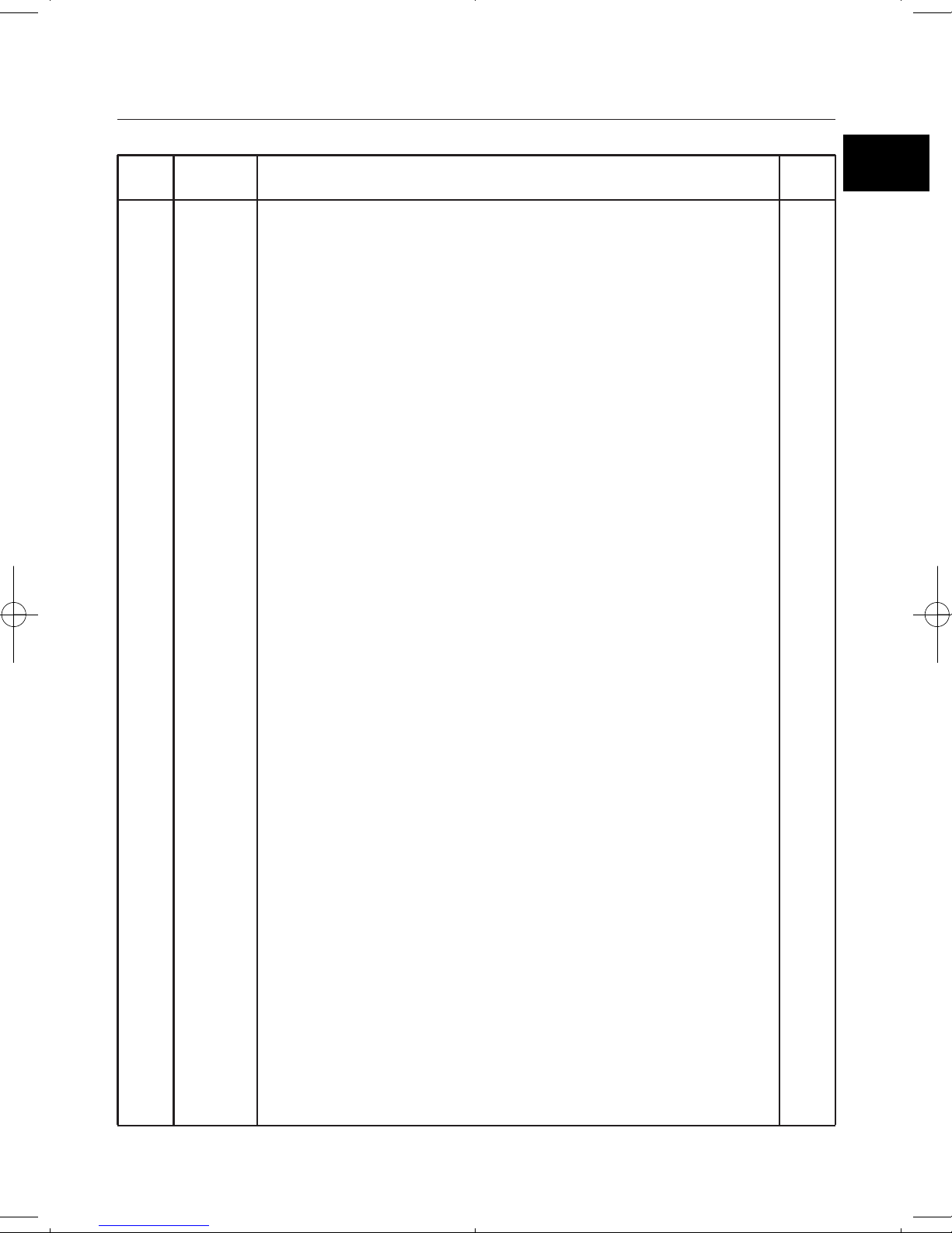
255 VALVE NOMENCLATURE
1
2
3
4
5
6
7
8
9
10
*
*
11
12
13
14
15
16
17
1294650
1033784
1010429
1010428
1235640
1235341
1236246*
1001404
1040459
1001986
1000250
1239760
1031402
1031403
1031404
1031405
1031406
1031407
1006093
1235353
1236251
1236269
1000226
1035730
1035731
1035732
1035733
1035734
1035735
1035736
1000269
1000209
1000210
1000211
1000212
1002130
1000214
1000215
255 Valve Assembly, w/o flow controls
255 Tank adapter New style
O-Ring BN
O-Ring EP
Top plate, 255 Valve, 700/860 Series controller
Spring One piece 255 valve
Cover,Valve, 255/Performa, 700/860 Series controller
O-Ring group : tank adapter
O-Ring group : piping boss
13/16 inch rubber insert (optional)
Valve disk kit - standard
Blending valve kit 900/700 series top plate
Locking bar
English language locking bar
French language locking bar
German language locking bar
Italian language locking bar
Japanese language locking bar
Spanish language locking bar
Locking bar screw N° 8-9/196 inch
Camshaft options
Cam 255/700-860 series valve, STD, black
Cam 255/700-860 series valve,TWIN, tan (insert)
Motor/Optical cable assembly, 700 series controller
Screen/Cap Assembly w/ O-Ring
Injector (high efficiency) Options
“E” Injector (high efficiency) - yellow
“F” Injector (high efficiency) - peach
“G” Injector (high efficiency) - tan
“H” Injector (high efficiency) - lt purple
“J” Injector (high efficiency) - lt blue
“K” Injector (high efficiency) - pink
“L” Injector (high efficiency) - orange
Injector cap with O-Ring
Drain control assembly with O-Ring
N°7 (1.2 gpm; 4.5 Lpm)
N°8 (1.6 gpm; 6.1 Lpm)
N°9 (2.0 gpm; 7.6 Lpm)
N°10 (2.5 gpm; 9.5 Lpm)
N°12 (3.5 gpm; 13.2 Lpm)
N°13 (4.1 gpm; 15.5 Lpm)
N°14 (4.8 gpm; 18.2 Lpm)
1
1
1
1
1
1
1
1
1
1
1
1
1
1
1
1
1
1
1
Code
Part
number
Description Qty
21
En
Page 22
255 VALVE NOMENCLATURE
18A
18B
19
20
21
22
*
1000222
1243510
1032416
1032417
1235373
1238861
1030502
1033066
Regenerant Refill controller, No ball
Regenerant Refill controller
Air Check Kit
Air Check Kit 3/8 inch male
Air Check Kit 1/4 inch male
Module, Sensor, Photo interupter
Motor w/Spacer & Pinion, 700 Series controller, 12V, 50/60 Hz
Ball Flow Control
New to Old Style Aircheck Adapter
1
1
1
1
1
1
Code
Part
number
Description Qty
22
En
Page 23
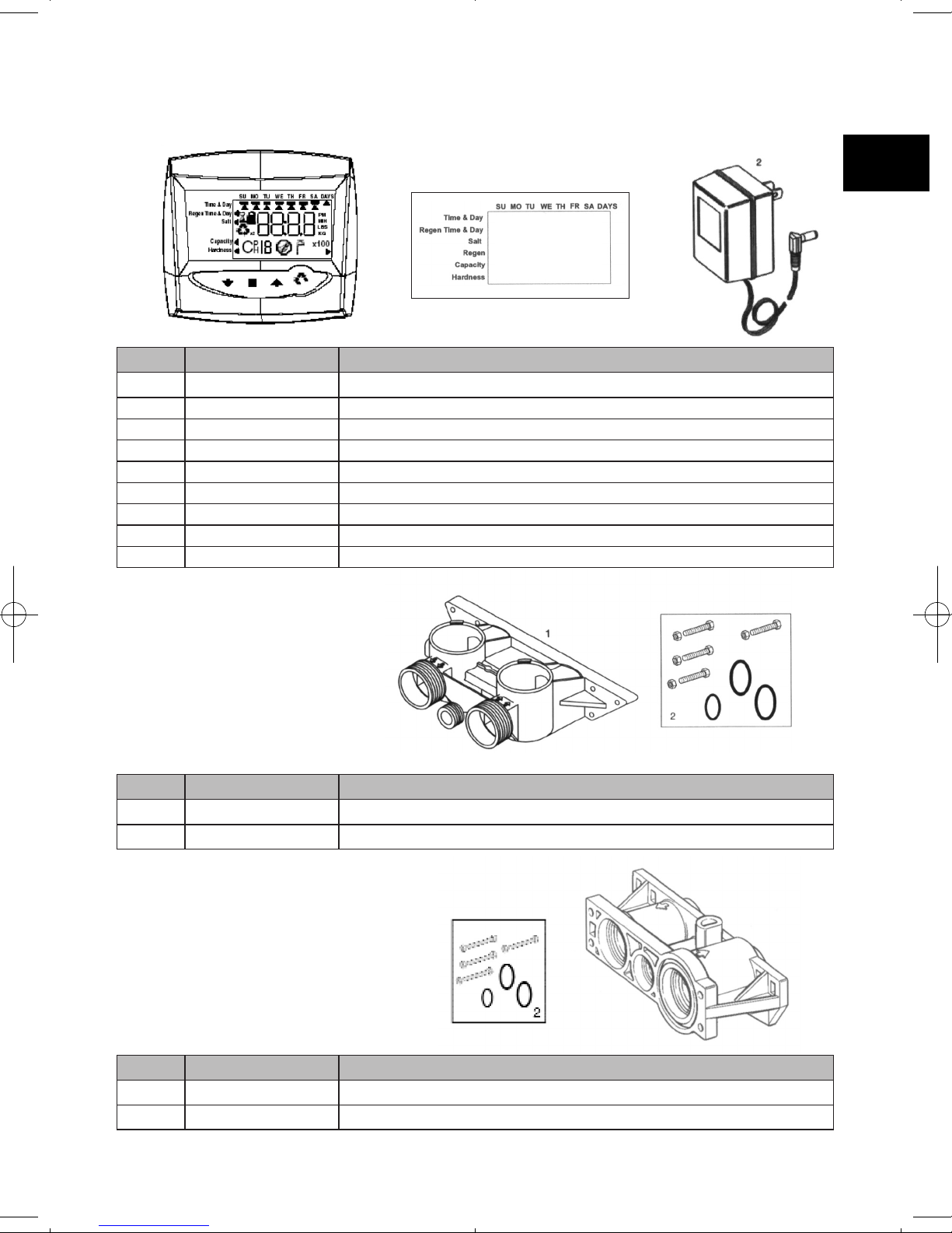
740/760 Control
Code Part Number Description
1 1234336 Kit chlorine generator
2 1242411 Extension cable for remote blezel
3 1263910 Overlay 740
4 1263911 Overlay 740C
5 1263912 Overlay 740F
6 1263913 Overlay 760
7 1263914 Overlay 760C
8 1263914 Overlay 760F
9 1000814 Transformer
Meter Adapter - Bypass Valve
Code Part Number Description
1 1040769 By-pass
2 1040524 Installation Kit
Code Part Number Description
1 1032351 Turbine + Installation Kit
2 1032350 Installation Kit
Meter Adapter
23
En
 Loading...