

Page 1
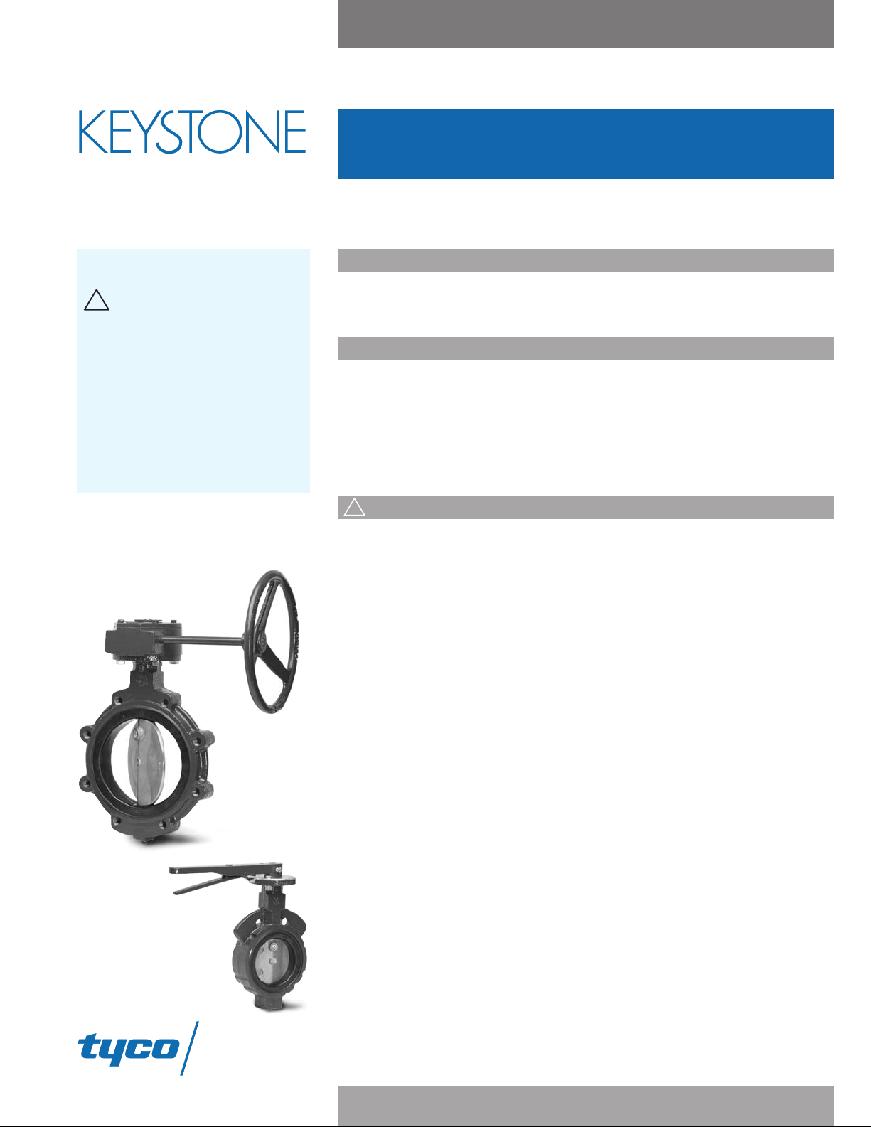
Keystone Figure 221/222 Butterfly Valve
Flow Control
!
!
Installation and Operating Instructions
Before installation or maintenance, these instructions
must be fully read and understood.
Please read these instructions
carefully.
This symbol indicates important
messages and safety instructions.
Potentially dangerous practices:
disregarding instructions.
•
• improper use of product.
• use of insufficiently qualified
personnel.
Application pressure/temperature must
not be higher than the pressure/
temperature limits shown on the technical
data sheet.
Introduction
The Keystone Figure 221/222 is a rubber lined butterfly valve which has a maximum
working pressure of 250 psi over a temperature range of -20°F to +250°F, depending on
seat material. The Figure 221/222 utilizes a molded seat design.
Flange and pipeline compatibility
Keystone butterfly valves are designed for installation between ANSI Class 125/150 flat or
raised faced flanges. Gaskets are not required. Lined pipe, heavy wall pipe or flanges must
have a minimum allowable inside diameter at the centered body face to clear the disc
sealing edge when opening the valve.
Weld neck flanges (flange ID approximates flange bore) are recommended to ensure
maximum valve performance; however, slip-on flanges may be used.
Do not weld near the valve, as this will result in serious damage to the valve.
Safety related information
1. If in any doubt regarding any aspect of Figure 221/222 valves, contact your local Tyco
Flow Control sales office for guidance.
2. Only use properly qualified personnel for installation.
3. Ensure that the pipeline is fully drained or vented before removing the valve from the
pipeline.
4. Use appropriate protective equipment/clothing, such as goggles, safety shoes,
industrial gloves.
5. This product is not intended for use in areas where external fire is a potential hazard.
6. The piping design must take into account the following factors and any other factors
which are not listed here, but known to be relevant to the safe operation of the
installation.
6.1. Valve weights which are shown in the technical data sheet.
mation of condensate in gas pipelines.
6.2. For
6.3. Elimination of turbulence and vortex potential at the valve.
6.4. Pipeline vibrations.
6.5. The piping design should preclude the occurrence of water hammer at the valve.
7. The valve design has not taken into account earthquake loading or traffic vibration.
8.
The nor
mal shelf life of the Figure 221/222 valve seat is 5 years under clean, dry
ambient and conditions without UV exposure prior to installation.
9. Tighten all flange bolts as per the nominated flange standards using the diagonal
sequence method.
Total Flow Control Solutions™
Cop
yright
yco Flow Control. All rights reserved. KEYMC-6254-US-0810
T
2008
©
Page 2
Keystone Figure 221/222 Butterfly Valve
!
Installation and Operating Instructions
Installation Instructions
Installation in pipeline
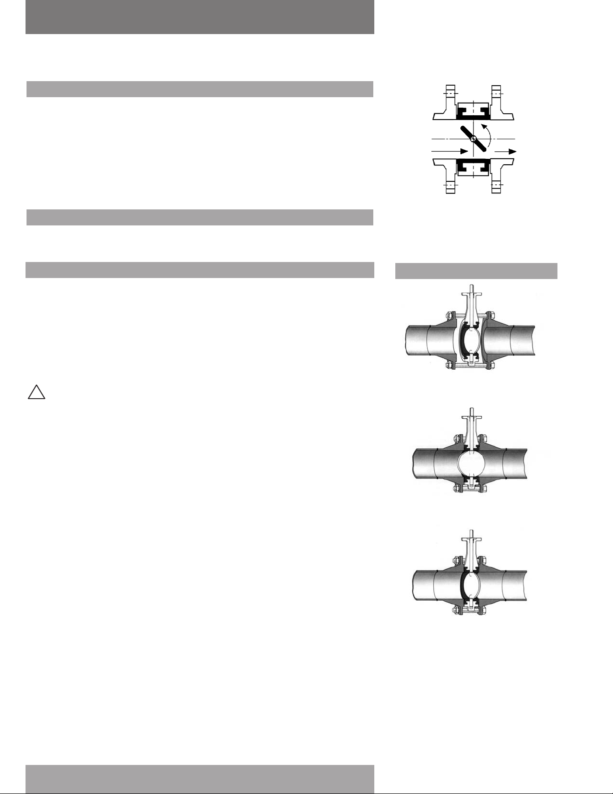
Figure 221/222 valves are bi-directional and there is no need to identify upstream and down
stream orientation. These valves can be installed in vertical or horizontal pipelines and any
intermediate orientation.
There is no restriction on the valve stem position (vertical, horizontal or oblique), although for
slurry service and media, which have a tendency to deposit sediment, the recommended
installation position is with the stem horizontal and the lower disc edge opening downstream.
Do not use flange gaskets or sealing compounds. The Keystone seat face design eliminates the
need for gaskets.
Flow
pen
O
Maintenance
Routine maintenance or lubrication are not required.
Installation in an existing system
Consideration should be given to the location of the valves in t he piping system. The valve
1.
should not be placed too close to other valves, elbows, etc. as its performance may be
affected. It is recommended that the valve have a minimum of six pipe diameters upstream
and four pipe diameters downstream between it and other valves, elbows, etc. in the piping
system.
2. Ensure that the flanges are clean, undamaged and compatible with the valve.
3. Check that the gap between the flanges can accommodate the valve face to face dimension.
4. Spread the flanges using suitable tooling such as flange spreaders to enable ease of
insertion of the valve between the flanges.
Warning: Do not use the valve as a lever.
5. Open the valve until the disc is free of the seat but still within the valve body (about 5° open).
6. Loosely insert two or more flange bolts through the holes in the lower part of the flanges to
help support the valve.
7. Carefully slide the valve between the flanges, center the valve body with the pipeline axis,
and insert the remaining flange bolts.
8. Open the valve fully, checking that the disc edge does not interfere with the pipeline bore.
9. Remove any flange spreaders that have been used and at the same time tighten the flange
bolts “hand tight”. Ensure that the valve remains centered to the pipeline axis by slowly
closing the valve (clockwise rotation of the disc stem) to check that adequate clearance has
been maintained between the disc edge and the pipeline bor
10. Re-open the valve (counter clockwise rotation of the disc stem) and tighten all flange bolts as
per flange standar
Operate the valve to the desir
11.
ds using the diagonal sequence method.
ed position.
e.
Preferred Mounting
Existing system
1. Spread the flanges with the adequate
tooling. Insert some flange bolts to bear
the valve
Open the valve and remove the flange
2.
eads.
spr
Close the valve clockwise, r
3.
position and cross-tighten all bolting.
yco Flow Control. All rights reserved. KEYMC-6254
T
2008
©
yright
Cop
2
eturn to open
Page 3
Keystone Figure 221/222 Butterfly Valve
!
Installation and Operating Instructions
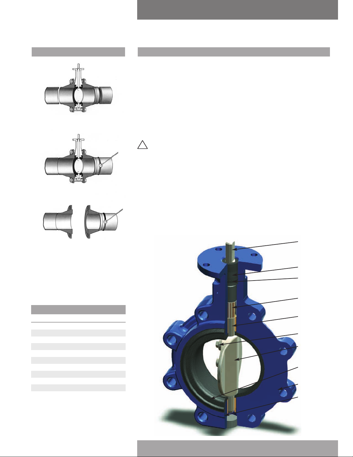
New system
1. Center a flange-valve-flange assembly
between the pipes.
2. Tack weld the flanges to the pipes.
Installation in a new system
It is common practice to use the valve to help in alignment of the flanges prior to welding the
flanges into the pipeline. In such cases, the following instruction applies:
1. Align both mating flanges with the valve center line and secure in position using the
flange bolts.
2. Position the flange/valve/flange assembly in the pipeline.
3. Tack weld the flanges to the pipeline.
4. Remove the flange bolts and the valve.
5. Finish weld the flanges to the pipeline and allow to cool fully.
. Follow the procedure for installation in an existing system.
6
Warning: Do not finish weld the flanges to the pipeline with the valve still assembled to
the flanges as this will result in serious damage to the valve seat.
3. Remove the valve and finish weld. Install
the valve according to the procedure in
the left column.
arts
P
Item No. Part Number Quantity
1
Body
1
2 Bearing 2
3
Seat
1
4 Disc 1
5
Stem
1
6 Spacer 2
7 Packing 1
8 Bushing 1
9 Torque plug 1
10
Body plug
1
5
8
7
6
2
9
4
3
1
10
Cop
3
yco Flow Control. All rights reserved. KEYMC-6254
T
2008
©
yright
Page 4
Keystone Figure 221/222 Butterfly Valve
Installation and Operating Instructionss
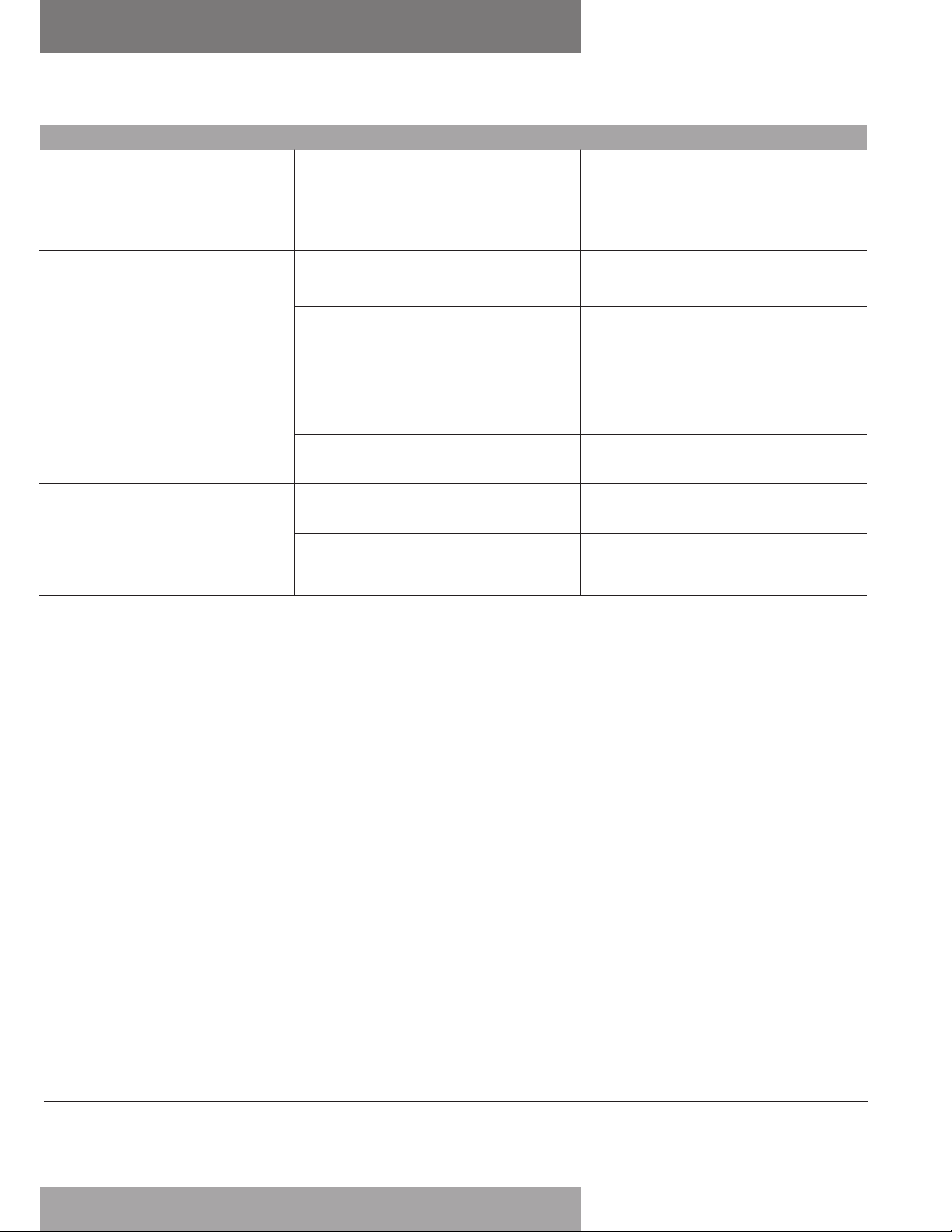
Troubleshooting
Symptom Probable Cause Solution
Valve opens only a few degrees
and stops (it will not open to the
f
ull angle desired).
Leakage past the flange face.
Leakage in the closed position
(leakage in the pipeline).
Excessively high torque.
Improper installation. The valve is
improperly aligned.
1. Flange bolts are not evenly torqued.
2. Improper flanges.
The disc is not closing fully:
1. Actuator is not properly adjusted.
Line pressure exceeds the valve’s
2.
working pressure.
1. Obstruction in the pipeline.
2. Scale build-up on stem or seat.
Loosen the flange bolts, re-align the
valve with flanges, and re-tighten the
flange bolts to correct torque per ANSI
requirements.
1
. Loosen the flange bolts and tighten the
flange bolts to the correct torque per
ANSI requirements.
2. Refer to “Flange and pipeline
compatibility” on page 1.
1. Refer to actuator adjustment
procedures.
2. Reduce line pressure to the valve’s
working pressure.
1. Remove valve from pipeline and
remove obstruction.
3. Open and close the valve several
times. Operate the valve at least once
a month. Check the valve seat for
deterioration.
.tycoflo
www
.keystonevalves.com
www
ut makes no representation as to its comprehensiveness or accuracy. This IOM is intended only as a guide to TFC products and services.
w Control (TFC) pro
yco Flo
T
Individuals using this IOM m
NO REPRESENTATIONS OR WARRANTIES, EITHER EXPRESS OR IMPLIED, INCLUDING WITHOUT LIMITATION ANY WARRANTIES OF MERCHANTABILITY OR FITNESS FOR A PARTICULAR PURPOSE
WITH RESPECT
KIND OR NA
P
TURE, INCLUDING INCIDENT
yright
atents P
©
atents and P
Cop
vides the inf
ercise their independent judgment in e
x
ust e
TO THE INFORMATION SET FORTH HEREIN OR THE PRODUCT(S) TO WHICH THE INFORMATION REFERS. ACCORDINGLY, TFC WILL NOT BE RESPONSIBLE FOR DAMAGES (OF ANY
ending in the U
yco Flow Control. All rights reserved. KEYMC-6254
T
2008
AL, INDIRECT
and foreign countries. Tyco reserves the right to change product designs and specifications without notice.
.
.S
mation herein in good f
or
aith b
aluating product selection and deter
v
, OR CONSEQUENTIAL DAMAGES) RESULTING FROM THE USE OF OR RELIANCE UPON THIS INFORMATION.
wcontr
ol.com
mining product appropr
or their particular purpose and system requirements. TFC MAKES
iateness f
4
 Loading...