

Page 1
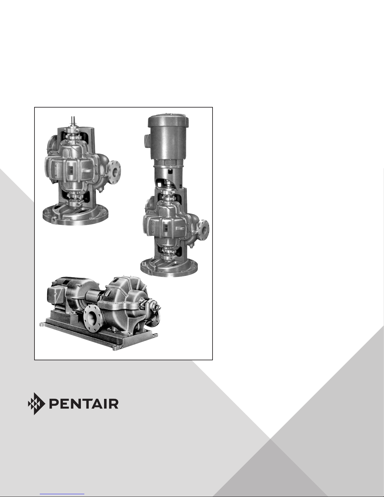
FAIRBANKS NHUIS
INSTRUCTION AND REPAIR MANUAL
HORIZONTAL
SPLITCASE PUMPS
Model 1940
Model
1900 SERIES
ENGLISH: PAGES 2-36
INSTRUCTION AND REPAIR MANUAL
NOTE! To the installer: Please make sure you
provide this manual to the owner of the equipment or to the responsible party who maintains
the system.
Model 1910
Models 1920 and
1920F
Part #FM-03-529 | © 2018 Pentair plc. | 11/19/18
Page 2

TABLE OF CONTENTS:
WARRANTY HIGHLIGHTS ...........................................3
INTRODUCTION ..............................................................5
GENERAL ...................................................................5
CAUTION & SAFETY NOTICE .................................. 5–6
PUMP IDENTIFICATION ..............................................6
SAFETY NOTES ...................................................... 6–7
HOUSEKEEPING ......................................................... 7
ENVIRONMENTAL CONDITIONS .................................7
STORAGE OF PUMPS ...................................................... 7
GENERAL ................................................................... 7
CONSIDER A UNIT IN STORAGE .................................. 7
SHORT-TERM STORAGE ........................................8
LONG-TERM STORAGE ..........................................8
THREE MONTHS TO ONE YEAR ..............................8
OVER ONE YEAR ................................................ 8–9
REMOVING FROM STORAGE .......................................9
INSTALLATION ..............................................................9
NET POSITIVE SUCTION HEAD (NPSH) ..................... 10
WET WELL DESIGN .................................................. 10
LOCATION AND HANDLING ................................... 10–11
FOUNDATION ............................................................ 11
LEVELING OF THE UNIT ............................................ 11
GROUTING ............................................................ 11-12
PIPING ...................................................................... 12
INITIAL COUPLING ALIGNMENT ............................... 12
PERIODIC CHECK ..................................................... 13
AUXILIARY PIPING CONNECTIONS ........................... 13
ROTATION ................................................................ 14
OPERATION.................................................................. 14
GENERAL ................................................................. 14
OPERATING AT REDUCED CAPACITY ....................... 14
PRIMING ................................................................... 15
STARTING THE PUMP ............................................... 15
NORMAL OPERATION ...........................................15–16
STOPPING THE PUMP ............................................... 16
NORMAL SHUTDOWN ............................................... 16
EMERGENCY SHUTDOWN ........................................ 16
BEARING OPERATING TEMPERATURE ..................... 16
TROUBLESHOOTING .....................................................17
PUMP ...................................................................17–19
MOTOR ...........................................................20–21
REPAIR MANUAL .........................................................22
SERVICE ......................................................................22
LUBRICATION OF BEARINGS .............................. 22–23
REPAIRS ......................................................................23
DISASSEMBLY OF THE PUMP ............................. 23–25
MECHANICAL SEALS ..................................... 25–26
REASSEMBLY .................................................... 26–27
STANDARD PACKING ........................................... 27
MECHANICAL SEAL ....................................... 27–30
STARTING PUMP AFTER REASSEMBLY .................... 31
ORDERING PARTS ............................................... 31-35
RECOMMENDED SPARE PARTS ................................ 31
PREDICTED LIFE ...................................................... 31
PARTS LIST ..............................................................32
MISCELLANEOUS NUMBERED PARTS ......................32
PUMP EXPLODED VIEWS .................................... 33–35
Page 3

WARRANTY:
WARRANTY HIGHLIGHTS:
1. Seller warrants products of its own manufacture and workmanship under normal use and service according to
previously submitted terms and conditions letter or form KC585.
2. Accessories and components not manufactured by seller are warranted only to the extent of the original
manufacturer's warranty.
3. No allowances will be made for repairs or alterations effected without specific written authorization from seller.
4. Repairs or alterations made with other than genuine Fairbanks Nijhuis™ original equipment parts may void the
warranty and relieve the seller of all product responsibility.
5. This warranty is void unless the purchaser provides protective storage, installs and maintains the equipment in
accordance with manufacturer's instructions.
6. Under the terms of this warranty, seller shall not be responsible nor liable for:
3
a. Consequential, collateral or special losses or damages.
b. Equipment conditions caused by fair wear and tear, abnormal conditions of use, accident, neglect, or misuse of
said equipment.
c. Labor charges, loss or damage resulting from supplying of defective part(s) or improper repairs by unauthorized
person(s).
d. Damage caused by abrasive materials, chemicals, scale deposits, corrosion, lightning, improper voltage
or mishandling.
7. The above listed warranty highlights do not constitute our total terms and conditions regarding warranty.
Page 4
PRESTART-UP AND START-UP CHECK LIST
Contractor Pump Serial Number
Project Name Pump Model Number
Procedure Yes No N/A Comments
1. Shipment
Was there any damage in transit?
Were all items received?
2. Storage
Has equipment been protected from inclement weather?
Was equipment subject to flooding?
Have all bearings been protected from moisture?
3. Installation
Were retaining fasteners, used in shipping, removed prior to installation?
Is grouting under base properly compacted?
Is grouting of the non-shrink type?
Have proper anchor bolts been used?
Have the bolts been properly tightened?
Have both the suction and discharge been checked for pipe strain?
Are lube lines and seal water lines properly installed?
Are accessory items, RTD’s, bearing temp detectors, vibration sensors, etc.
mounted and properly installed?
Are lube lines purged of air and lubricant added? (pump and driver)
Are all safety guards in place?
Have impellers been checked for proper clearance?
4. Alignment
Has the alignment of driver to pump been checked?
Have indicator readings been taken?
5. Rotation
Has the rotation of the drives been checked for correctness?
Has the coupling been turned to assure free rotation of pump and motor?
6. System
Has the system been checked to ensure that it is free ot foreign matter which
could be damaging to the pump?
Is liquid available to the pump?
Has assurance been obtained from responsible parties that all piping is secure
and that the routing of flow has been established and is correct?
7. Start-Up
Has flow been established?
Have gauge readings been taken?
Has packing been adjusted to ensure proper lubrication of packing?
If pumps are equipped with mechanical seals, is the lubricating seal water
pressure a constant 10 to 15 psi above the discharge of the pump?
Is excessive vibration present?
Is bearing operating temperature excessive?
Customer’s Representative
Witnessing Start-Up
Date
Company
Name
Fairbanks Nijhuis™ Pump Corporation
Representative Conducting Start-Up
Date
Name
Page 5

1900 Series Horizontal Splitcase Pumps
Instruction and Repair Manual
CALIFORNIA PROPOSITION 65 WARNING:
This product and related accessories contain chemicals known to the State of California to cause cancer,
birth defects or other reproductive harm.
INTRODUCTION:
GENERAL:
Congratulations! You are the owner of the finest pump commercially available. If you give it the proper care as outlined
and recommended by this manual, it will provide you with reliable service and long life.
This manual contains information that is the result of engineering and research efforts. It is designed to supply adequate
instructions for the installation, operation and maintenance of your pump. Failure or neglect to properly install, operate
or maintain your pump may result in personal injury, property damage or unnecessary damage to
the pump.
These instructions apply to the pump only and have been prepared specifically for the pump supplied on this order. If your
operating conditions ever change, always refer to the factory for reapplication. Always refer to the manuals provided by
manufacturers of the accessory equipment for their separate instructions.
5
Variations exist in both the equipment used with these pumps and in the particular installation of the pump and driver.
Therefore, specific operating instructions are not within the scope of this manual but should be added by the parties
responsible for the operation of the entire station. The manual contains general rules and guidelines for installation,
operation and maintenance of the pump. If there are questions regarding the pump or its application, which are not
covered in this manual, please contact the factory as follows:
Fairbanks Nijhuis™
3601 Fairbanks Ave.
Kansas City, KS 66106
(913) 371-5000
For information or technical assistance on the drive source, contact the drive manufacturer local dealer or
representative.
To obtain additional data on hydraulics and pump selection and operation, we suggest you purchase both of the following
reference books:
A. Fairbanks Nijhuis Hydraulic Handbook available from the factory.
B. Hydraulic Institute Standards
Hydraulic Institute
9 Sylvan Way
Parsippany, NJ 07054-3802
CAUTION AND SAFETY NOTICE:
The installation, use and operation of this type of equipment is affected by various federal, state and local laws and the
regulations concerning OSHA. Compliance with such laws relating to the proper installation and safe operation of this
type of equipment is the responsibility of the equipment owner, and all necessary steps should be taken by the owner to
assure compliance with such laws before operating the equipment. In addition WARNING and CAUTION notes are located
throughout this manual. They should be read and observed.
The following symbols are used to alert maintenance personnel to procedures that require special attention or which
could damage equipment or could be dangerous to personnel.
11/12/18
Page 6

6
1900 Series Horizontal Splitcase Pumps
Instruction and Repair Manual
DANGER:
Indicates an imminently hazardous situation which, if not avoided, will result in death or serious injury.
WARNING:
Indicates a potentially hazardous situation which, if not avoided, could result in serious injury.
CAUTION:
Indicates that improper practices will result in equipment malfunction or failure.
NOTES:
Instructions that will aid in installation, operation, maintenance or that clarify a procedure.
PUMP IDENTIFICATION:
Pertinent nameplate information is shown below. It will aid in obtaining the correct replacement parts for your pump. The
serial number is stamped on the discharge flange.
Pump
Serial Number
Model Number
Pump Size
Number Stages
GPM
Head (feet)
*To be copied from motor nameplate.
Speed (RPM)
Driver
Manufacturer
Horsepower
Serial Number*
Full Load Amps
Phase / Hertz / Volts
SAFETY NOTES:
These warnings apply to pumps supplied by Fairbanks Nijhuis™. Refer to the manuals supplied by the driver or control
manufacturers for additional warnings before operating this equipment.
Before attempting to service this pump, familiarize yourself with this manual.
DANGER:
Disconnect or lock out the power source to ensure the pump will not start. Check with appropriate electrical
test equipment.
Do not attempt to service the pump until the electrical power has been disconnected and it has been verified that the
pump cannot start.
Certain procedures in disassembly and assembly require parts be heated to high temperatures. Heat resistant gloves
must be worn when handling heated parts. Heated parts can cause severe personal injury.
After the pump has been installed make certain that the pump and all piping connections are tight and are properly
supported prior to start-up and operation.
WARNING:
CAUTION:
11/12/18
Page 7

1900 Series Horizontal Splitcase Pumps
Instruction and Repair Manual
WARNING:
Do not operate the pump without the protective guards in place over the rotating parts. Exposed rotating parts can
catch clothing, fingers, or tools, causing severe injury to personnel.
CAUTION:
This pump is designed for the exclusive use of pumping water. It should not be used for pumping other media unless a
specific Purchase/Buyer agreement is negotiated.
WARNING:
Because many installations use automatic starting equipment, the pump unit may start at any time
without warning.
HOUSEKEEPING:
The area surrounding the pump installation area should be kept free of rags and debris. The area should be kept clean and
dry and should be checked periodically to ensure there is no water, oil or grease on the floor which could cause accidental
slippage of maintenance personnel.
7
The pump and driver should be kept clean. Any spillage of lubricants on the pump/driver during periodic maintenance
should be wiped clean. Loose ends of packing should be picked up and properly discarded after repacking the pump.
Drain lines should be checked to ensure they are functioning properly.
Driver ventilation ports should be kept free to ensure proper cooling of the motor.
ENVIRONMENTAL CONDITIONS:
Pumps are designed to operate in moderate to severe environmental conditions. Normally they should not be operated
in an ambient temperature exceeding 130°F or in conditions that would allow the sealing water or the pumped media to
freeze.
STORAGE OF PUMPS;
GENERAL:
If the equipment is not to be immediately installed and operated, store it in a clean, dry, well-ventilated place, free from
vibrations, moisture and rapid or wide variations in temperature.
Improper storage and preservation could damage the equipment which would result in non-warranty covered restoration
requirements or non-warranty covered product failures.
CONSIDER A UNIT IN STORAGE:
1. When it has been delivered to the job site and is awaiting installation.
2. When it has been installed but operation is delayed pending completion of construction.
3. When there are long (30 days or more) periods between operation cycles.
4. When the pump is shut down for periods of longer than 30 days.
11/12/18
Page 8

8
1900 Series Horizontal Splitcase Pumps
Instruction and Repair Manual
SHORT-TERM STORAGE:
Short-term storage is when the pump will be stored for periods not exceeding three months. The following are the shortterm storage requirements:
A. Rotate the shaft for several revolutions at least once every two weeks to:
1. Coat the bearing with lubricant.
2. Retard oxidation or corrosion.
3. Prevent possible false Brinelling.
LONG-TERM STORAGE:
Long-term storage is when the pump will be stored for periods exceeding three months. The following are long-term
storage requirements:
THREE MONTHS TO ONE YEAR:
1. Remove gland halves, packing and seal water ring from the stuffing box. Package them in a suitable container to
prevent loss or damage. Coat the inside of the stuffing box with grease.
• If the pump is equipped with a mechanical seal, remove the pipe plug in the stuffing box and pour at least 4
ounces of mineral oil into the seal housing. Reinstall the pipe plug.
2. Fill the bearing housings with specified lubricating grease until grease exits from relief fittings.
3. Wipe clean all exposed machined surfaces and coat with a heavy layer of grease or other equivalent rust
prevention material.
4. Cover the suction and discharge of the pump with cardboard or wood to prevent entry of foreign material
or varmints.
5. Rotate the pump shaft several times by hand repeating this every two (2) weeks during storage. Rotation of the
shaft will coat the bearings and retard oxidation, preventing possible false Brinelling.
OVER ONE YEAR:
1. Remove gland halves, packing and seal water ring from the stuffing box. Package them in a suitable container
to prevent loss or damage. Coat the inside of the stuffing box with grease.
• If the pump is equipped with a mechanical seal, remove the pipe plug in the stuffing box and pour at least 4
ounces of mineral oil into the seal housing. Reinstall the pipe plug.
2. Fill the bearing housings with specified lubricating grease until grease exits from relief fittings.
3. Clean all accessible machined surfaces to remove dirt, corrosion, grease and any other foreign matter. Clean
water passages to remove all foreign matter. Dry the pump to remove all moisture.
4. Spray flushing water and seal water piping with P-7 medium preservative oil. Seal all water inlet connections
with pipe caps or plugs.
11/12/18
Page 9

1900 Series Horizontal Splitcase Pumps
Instruction and Repair Manual
5. All internal surfaces in contact with water should be sprayed with Grade 5 of MIL-C-ISI73 Corrosion Preventive
Compound, solvent cut back. Drain all excess compound by removing drain plugs. Treat the drain plugs with P-I
or P-I9 preservative, replace and tighten.
6. Apply P-2 preservative to all exposed shaft surfaces.
7. Cover inlet and outlet nozzles with Grade A of MIL-B-I21 barrier material and a blank flange of mild steel
(1/16" minimum thickness), tempered hardboard (114" minimum thickness) or fully waterproofed plywood
(114" minimum thickness). Secure the flanges with at least 4 bolts with lockwashers.
8. Wrap the shaft, the frame and the stuffing box area with grease-proof barrier material, conforming to Type I,
Grade A of MIL-B-I2I. Secure the barrier with waterproof pressure sensitive tape.
9. Rotate the pump shaft several times by hand repeating this every two (2) weeks during storage. Rotation of the
shaft will coat the bearings and retard oxidation, preventing possible false Brinelling.
REMOVING FROM STORAGE:
After the storage period is over and prior to operating the pump, remove the cover on the thrust bearing housing for
inspection of the bearing lubricant. If any water or foreign matter is found in the lubricant, all bearings must be cleaned
and the lubricant replaced.
9
Refer to the Installation section of this manual for installation instructions.
After the pump has been set and grouted in place and is ready for operation, the following steps should be followed:
1. Reinstall the packing, seal water ring and gland. Adjust in accordance with this manual. Flush the mineral oil out of
the mechanical seal if unit is so equipped.
2. Remove bearing housing covers and remove one-half of the grease in bearing housings. Remove all grease relief
fittings and grease relief nipples from upper and lower bearing housings.
3. Start the pump per start-up instructions and permit grease to be purged from each bearing housing. Do not install
grease relief piping until purging has completely stopped after the pump has been in operation for at least eight (8)
hours. Observe bearing temperatures, and stop and start the pump or run it at reduced speed until temperatures
stabilize within the specified limits.
4. Stop the pump, wipe any grease off the shaft and bearing frame and place the pump in service per instructions in
this manual.
DANGER:
Do not attempt to clean the pump until electrical power has been disconnected and it has been verified that the pump
cannot start.
INSTALLATION:
Carefully read all sections of this manual and all other instruction manuals provided by manufacturers of other equipment
supplied with this pump.
Upon receipt of the shipment, unpack and inspect the pump and driver assemblies and individual parts to ensure none
are missing or damaged. Carefully inspect all boxes and packing material for loose parts to ensure none are missing or
damaged. Carefully inspect all boxes and packing material for loose parts before discarding them. Report immediately to
the factory, and to the transportation company involved, any missing parts or damage incurred during shipment, and file
your “damaged and/or lost in shipment” claim with the carrier immediately.
11/12/18
Page 10

10
1900 Series Horizontal Splitcase Pumps
Instruction and Repair Manual
NET POSITIVE SUCTION HEAD (NPSH):
NPSH can be defined as the head (energy) that causes liquid to flow through the suction pipe and enter the eye of the
impeller.
NPSH is expressed in two values:
1. NPSH required (NPSHR).
2. NPSH available (NPSHA).
It is essential that NPSHA always be greater than NPSHR to prevent cavitation, vibration, wear and
unstable operation.
NPSHR is a function of the pump design and therefore varies with the make, size, capacity and speed of the pump. The
value for your pump can be obtained from your pump performance curve or the factory.
NPSHA is a function of your system and may be calculated as follows:
A. When the source of liquid is above the pump:
1. NPSHA = barometric pressure (feet) + static suction head (feet)* – friction losses in suction piping (feet)
– vapor pressure of liquid (feet).
B. When the source of liquid is below the pump:
1. NPSHA = barometric pressure (feet) static suction lift (feet)* – friction losses in suction piping (feet)
– vapor pressure of liquid (feet).
*The datum elevation plane for horizontal pumps is the pump centerline.
WET WELL DESIGN:
Generally, it is required that an evenly distributed flow of non-aerated water be supplied to the pump suction. Improper
wet well or sump design or insufficient suction pipe submergence can result in intake vortexing which reduces the
pump’s performance and can cause severe damage to the pump.
We recommend that you secure the advice of a qualified Consulting Engineer for the analysis and design of the wet well.
Significant engineering data on wet well design is provided in the Hydraulic Institute Standards.
Upon request, Fairbanks Nijhuis™ will review plans and give general comments on the installation, but will not approve
such plans for a specific installation and will accept no responsibility or liability for the performance of the pump
intake structure.
LOCATION AND HANDLING:
The pump should be installed as near the fluid as possible so a short direct suction pipe can be used to keep suction
losses at a minimum. If possible, locate the pump so the fluid will flow to the suction opening by gravity. The discharge
piping should be direct and with as few elbows and fittings as possible. The total net positive suction head available
(NPSHA), which includes the suction lift and pipe friction losses, must be greater than the net positive suction head
required (NPSHR) by the pump.
The pump and driver should be located in an area that will permit periodic inspection and maintenance. Head and access
room should be provided and all units should be installed in a dry location with adequate drainage.
11/12/18
Page 11
1900 Series Horizontal Splitcase Pumps
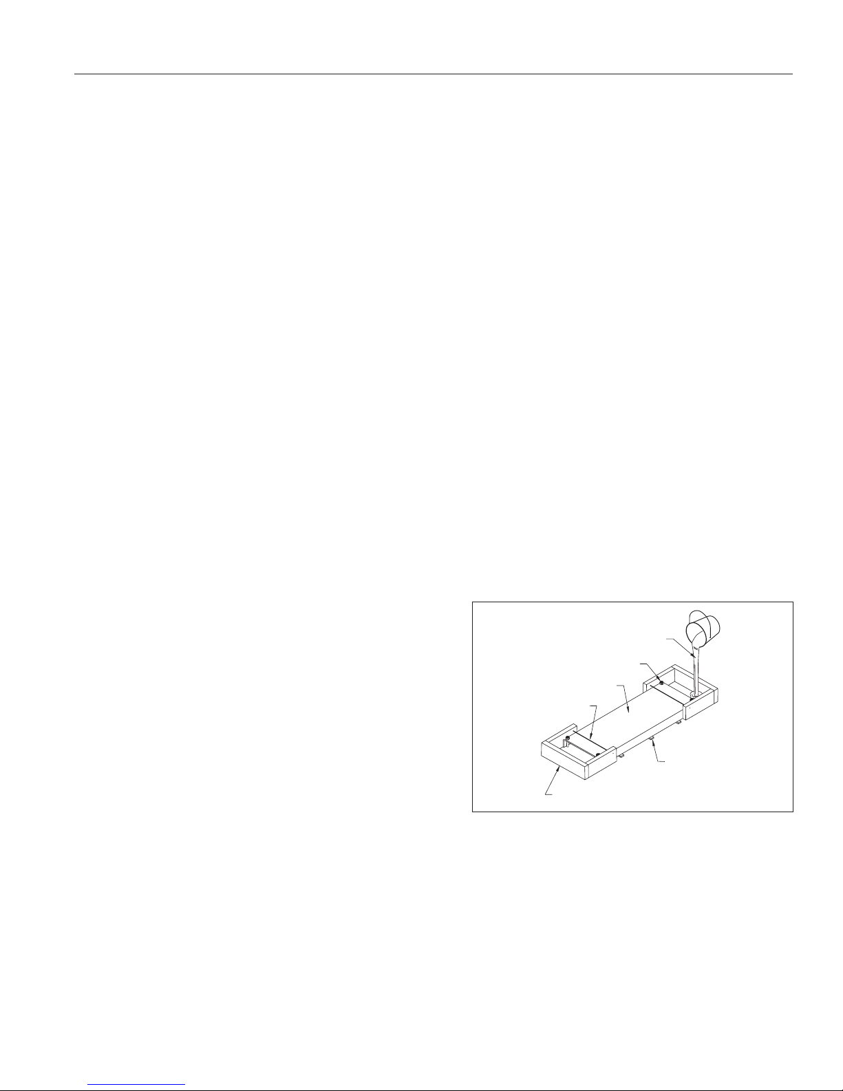
SHIMS TO LEVEL BASE PLATE
WOODEN DAM
ON BOTH ENDS
TWISTED TENSION WIRE
ROLLED STEEL BASE
FOUNDATION BOLTS
SOUPY GROUT
Instruction and Repair Manual
WARNING:
Do not pick up the complete unit by the driver eye bolts or pump shaft.
FOUNDATION:
The pump foundation should have a level surface and be of sufficient mass to prevent vibration and form a permanent
rigid support for the unit. The most satisfactory foundations are concrete with anchor bolts of adequate size embedded
in the foundation in pipe sleeves with an inside diameter 2-1/2 times larger than the bolt diameter. This will allow for final
accurate positioning of the unit.
Recommended anchor bolt design is available from the factory.
LEVELING OF THE UNIT:
Lower the unit onto the foundation and position the base so the anchor bolts are aligned in the middle of the holes in the
base. Disconnect the coupling halves and do not reconnect until all alignment operations are complete.
Set the base on metal shims or metal wedges placed directly under the part of the base carrying the greatest weight, and
spaced close enough to give uniform support and stability.
11
Adjust the metal shims or wedges until the shaft of the pump and driver are level or vertical as appropriate and until pump
and driver shaft are aligned with each other. Make sure that all shims or wedges fit firmly between the foundation and the
base.
If leveling nuts are installed on the anchor bolts and are used for alignment, follow the same procedure as with shims
or wedges. Support the base with additional shims or wedges if necessary. Make sure that all nuts and shims are in firm
contact with the base. Tighten the foundation bolts snugly, but not too firmly, and recheck the shafts for alignment
before grouting.
GROUTING:
IMPORTANT:
The pump base must be set level to avoid any mechanical
difficulties with the pump or motor. The 1900 pump was
properly aligned, if supplied with a motor, at the factory.
However, since the pump base is flexible, it may spring
and twist during shipment. Do not pipe the pump until it is
realigned.
Grouting the base plate prevents lateral movement of the base
plate, and improves the vibration absorbing characteristics of
the foundation by increasing its mass. A wooden dam should be
Figure 1. Grouting the Base for Frame Mounted Pumps.
constructed around the base plate to contain the grout while it is
being poured. The dam can be built tight against the base plate, or slightly removed from it as desired. Refer to Fig. 1. The
entire base plate should be completely filled with nonshrinkable type grout. Be sure to remove all air bubbles from the
grout.
CAUTION:
Damaging vibration may result if the base plate is not solidly in contact with the grout bed.
Do not fill the pipe sleeves with grout.
If leveling nuts are used, make sure they are not embedded in grout. Provide access in the grout to the leveling nuts so
that they can be backed off after the grout has cured.
11/12/18
Page 12

12
Allow the grout to fully cure before backing off the leveling nuts (if used) and firmly tightening the foundation bolts. Then
recheck the alignment before connecting the piping as even the highest quality nonshrink grouts contract slightly during
drying.
1900 Series Horizontal Splitcase Pumps
Instruction and Repair Manual
PlPING:
IMPORTANT:
All piping connections must be made with the pipe in a free supported state, and without the need to apply vertical or
side pressure to obtain alignment of the piping with pump flange.
All piping should be independently supported near the pump so that pipe strain will not be transmitted to the pump
casing. The weight of the piping and of the contained liquid must be considered in support design. The suction and
discharge piping should be one or two sizes larger than the pump flange sizes, especially where the piping is of
considerable length. Any flexible joints installed in the piping must be equipped with tension rods to absorb piping axial
thrust.
The suction pipe must be airtight and sloped upward to the pump flange to avoid air pockets which will impair
satisfactory pump operation. The discharge pipe should be as direct as possible with a minimum of valves to reduce pipe
friction losses.
A check valve and closing valve should be installed in the discharge line and a closing valve in the suction line. The check
valve, between the pump and closing valve, protects the pump from water hammer and prevents reverse rotation in the
event of power failure. The closing valves are used in priming, starting and when the pump is shut down. The pump must
never be throttled by the use of a valve in the suction line.
INITIAL COUPLING ALIGNMENT:
Check safety codes, and always install protective guard or shield as required by the various federal, state and local laws
and the regulations concerning OSHA.
The pump and driver were accurately aligned at the factory. However, it is impossible to maintain this alignment during
shipping and handling. Therefore it will be necessary for you to realign the pump and driver. Flexible couplings are not
universal joints. They should not be used to compensate for misalignment of the pump and motor shafts. Their function
is to transmit power from the driver to the pump while compensating for thermal expansion and shaft end movement.
The coupling faces should be far enough apart so that they do not make contact when the motor shaft is forced to the
limit of the bearing clearance toward the pump shaft.
In order to properly align the coupling, you will need a taper gauge or set of feeler gauges, and a straight edge.
There are two types of misalignment encountered with flexible couplings: angular misalignment, in which the shafts are
not parallel, and parallel misalignment where the shafts are parallel but not on the same axis.
To check angular alignment, insert a feeler gauge or taper gauge at any four places 90° apart around the coupling halves.
Insert shims under the driver feet until the same reading is obtained at all four check points. The pump and driver will
then be in angular alignment.
11/12/18
Page 13

1900 Series Horizontal Splitcase Pumps
STRAIGHT EDGE
PARALLEL MISALIGNMENT
ANGULAR MISALIGNMENT
WEDGE OR
THICKNESS GAUGE
PERFECT ALIGNMENT
13
Instruction and Repair Manual
Figure 2. Flexible Coupling Alignment.
To check parallel alignment, a straight edge should be held against the edges of the coupling halves at any four places
90° apart around the coupling. The straight edge should be parallel to the pump and driver shafts at all times. Insert shims
until the straight edge lies flat against both coupling halves at all four checkpoints. The pump and driver will then be in
proper parallel alignment. Refer to Fig. 2.
For fine alignment, 3500 RPM operation, for all other coupler types.
A dial indicator should be used when greater alignment accuracy is required. Use the following alignment tolerances
unless specified otherwise by the coupling manufacturer. On sleeve type couplings make sure there is at least 1/8" end
clearance between the sleeve and the two coupling halves.
To check angular misalignments, mount the dial indicator base to the coupling half, and position the dial indicator button
on the front or rear face of the opposite coupling half. Set the dial to zero, rotate both coupling halves together, making
sure the indicator button always indicates off the same spot. Misalignment values within 0.004 inches TIR per inch of
coupler radius is permissible.
To check parallel misalignment, mount the dial indicator base to one coupling half, or shaft and position the dial indicator
button on the outside diameter of the opposite coupling half. Set the dial to zero. Rotate both coupling halves together,
making sure the indicator button always indicates off the same spot. Misalignment within 0.004 inches TIR is permissible.
PERIODIC CHECK:
Realign the base after piping from time to time while the unit and foundation are new. Coupling misalignment can occur
because of shifts in grouting, foundation or because of large objects going through the pump causing shock loading
conditions.
Coupling alignment should be checked periodically for changes. Coupling misalignment can lead to or cause bearing
failure, coupling failure, shaft breakage, high power consumption, etc.
AUXILIARY PIPING CONNECTIONS:
Install any additional piping connections your pump may require such as water seal piping, stuffing box drain, baseplate
drain, and pressure gauges.
For satisfactory pump operation and life, these auxiliary pipe lines must be kept clean.
11/12/18
NOTE:
Page 14

14
1900 Series Horizontal Splitcase Pumps
Instruction and Repair Manual
ROTATION:
Before connecting the motor to the pump, bump start the driver and verify rotation is in the proper direction. The correct
pump rotation is indicated by a directional arrow on the pump casing.
OPERATION:
GENERAL:
This section contains general rules for operation. Because variations may exist in a particular installation between the
pumps, the drivers and the accessory equipment, specific operating instructions are not within the scope of
this manual.
WARNING:
Before starting or operating the pump, read this entire manual and especially comply with the following instructions:
A. Before starting the pump, install guards around all exposed rotating parts.
B. Before starting the pump, rotate the unit or assembly by hand to assure all moving parts are free.
C. Observe all caution or danger tags attached to the equipment.
D. Never run the pump dry as the close running fits within the pump are lubricated by the liquid. Running dry may result
in pump seizure.
E. Before starting the pump, fill the casing and suction line with liquid. The pump may be primed by using a
priming system.
F. If excessive vibration or noise occurs during operation, shut the pump down and consult a Fairbanks Nijhuis™
representative.
G. Before starting a packed box pump, adjust the packing so there is sufficient leakage to lubricate the packing and
assure a cool stuffing box. (See maintenance instructions.)
OPERATING AT REDUCED CAPACITY:
In a typical application covering a wide range of flow rates, a variable speed driver is often used to adjust pump capacity,
and this is taken into consideration by Fairbanks Nijhuis when selecting the pump and impeller trim. Although these
pumps are applicable over a wide range of operating conditions, care should be exercised when doing so, especially
when the actual conditions differ from the sold-for conditions. You should always contact your nearest Fairbanks Nijhuis
distributor or factory before operating the pumps at any condition other than that for which they
were sold.
Generally, these pumps can be operated continuously at a capacity equal to 25% of the pump capacity at the best
efficiency point, and at higher capacities. At capacities less than 25% of best efficiency point capacity, we recommend
that the pumps be operated for intermittent periods of time only.
11/12/18
Page 15

1900 Series Horizontal Splitcase Pumps
Instruction and Repair Manual
PRIMING:
The priming procedure is different for positive and negative suction head systems and the following procedures should
be followed:
A. Positive suction head.
1. Open the vent on the highest point on the pump casing.
2. Open all suction valves.
3. Allow the liquid to flow from the vent hole until all air bubbles are vented, and then close the vent.
4. The pump is now primed.
B. Negative suction head.
1. Install the priming system on the vent on the highest point of the pump casing.
2. Close the discharge valve.
15
3. Open the suction valve.
4. Start the priming system.
5. Run the priming system until a continuous stream flows through the suction line, then close the valve to
the vent.
6. The pump is now primed.
STARTING THE PUMP:
A. After the pump is primed, and with the discharge valve closed and the suction valve open, start the driver according
to the driver manufacturer’s instructions.
B. Open the discharge valve slowly to prevent water hammer.
C. Immediately after the pump has been started, check bearing temperature, stuffing box lubrication and operation,
and pump noise level. Continue to monitor these values for the first several hours of operation.
NORMAL OPERATION:
Monitor the following during running cycles:
A. Unit vibration or noise.
B. Driver lubrication.
C. Pump lubrication.
D. Packing box leakage.
11/12/18
Page 16

16
Check the following before normal start-up:
A. Driver lubrication.
B. General condition of all equipment.
Start-up after a week or more downtime:
A. Repeat those procedures covered by initial start-up.
1900 Series Horizontal Splitcase Pumps
Instruction and Repair Manual
STOPPING THE PUMP:
Pump stations are usually designed to have the pumps started and stopped automatically using a controller. Since this is
a function of station design, the operators should be thoroughly familiar with the system’s operating parameters and in
the use of the controller. The general procedure to shut down the pump is as follows:
NORMAL SHUTDOWN:
A. Disconnect the electrical power.
1. Lock out the power to the driver.
DANGER:
Check power source with appropriate electrical test equipment to ensure driver cannot accidently start.
B. If the pump is to be removed for repair, close the suction and discharge valves.
EMERGENCY SHUTDOWN:
In the event of an emergency, shut off the power at the nearest switch. The operator or persons working around the
equipment should be familiar with locations of emergency shut-off points.
Many installations are equipped with emergency shut-off switches near the pump location. These locations should be
plainly marked and be readily accessible at all times.
The control panel (if used) may be equipped with an emergency stop button or switch.
BEARING OPERATING TEMPERATURE:
These pumps are designed to operate over a wide ambient temperature. The temperature, when measured on the
outside surface of the bearing housing, should not exceed 190°F. Temperatures in excess of 190°F may indicate
a lack of lubricant, or bearing problems. If the temperature exceeds this limit, the pump should be stopped and the cause
investigated and corrected.
11/12/18
Page 17

1900 Series Horizontal Splitcase Pumps
Instruction and Repair Manual
TROUBLESHOOTING:
PUMP:
Your Fairbanks Nijhuis™ pump has been engineered and carefully selected for your application. It should provide years of
trouble-free service. However, any piece of machinery is subject to wear and occasional malfunction.
To help you quickly isolate and rectify any malfunction, the following troubleshooting guide has been prepared.
Frequent use of the chart to determine the cause of minor operating problems may prevent a major problem or possible
breakdown of your pump.
TROUBLE PROBABLE CAUSE REMEDY
17
1. Pump fails to prime or loses its
prime.
2. No discharge from pump. a. Pump is not properly primed. a. Reprime the pump; refer to priming
a. Air leaks in suction lines. a. Clean and tighten all suction
prime connections; relocate
suction inlet in liquid source.
b. Suction strainer is clogged. b. Remove dirt, leaves, or other
material from the strainer.
c. Suction lift is too high. c. Re-evaluate pump requirements
and correct suction conditions.
d. Defective priming valve. d. Replace valve.
e. Defective packing or seal. e. Replace packing or seal.
troubles and remedies.
b. Total head is too high. b. Re-evaluate head calculations;
measure elevation differences
between pump and liquid source
and pump discharge point. Consult
your local Fairbanks Nijhuis sales
office.
c. Driver is not operating at rated
speed.
d. Impeller or discharge line is
clogged.
c. Check voltage of electric motor;
check steam pressure of steam
turbine; check engine RPM’s.
Refer to appropriate maintenance
manuals for possible troubles and
corrective action.
d. Back flush pump to clear
obstruction; disassemble pump
and/or piping and remove
obstruction.
11/12/18
e. Wrong direction of rotation. e. Check wiring against diagram
motor nameplate and in controller;
reverse any two power leads on a
three phase motor, replace a single
phase motor.
f. Pump is vapor bound. f. Provide additional pressure on
liquid being pumped by elevating
liquid source or pressurizing the
supply tank.
Page 18

18
1900 Series Horizontal Splitcase Pumps
Instruction and Repair Manual
TROUBLE PROBABLE CAUSE REMEDY
3. Pump does not deliver rated
capacity.
a. Pump is not properly primed. a. See 2a above.
b. Suction lift is too high. b. See 1c above.
c. Excessive air in liquid. c. See 1a above.
d. Air leakage through stuffing box. d. See 1e above.
e. Driver is not operating at rated speed. e. See 2c above.
f. Impeller is clogged. f. See 2d above.
g. Wearing rings are worn. g. Replace wearing rings.
h. Impeller is damaged. h. Replace impeller.
i. Pump is vapor bound. i. See 2f above.
4. Insufficient pressure. a. Excessive air in liquid. a. See 3c above.
b. Driver is not operating at rated speed. b. See 2c above.
c. Wrong direction of rotation. c. See 2e above.
d. Total head is too high. d. See 2b above.
e. Wearing rings are worn. e. See 3g above.
f. Impeller is damaged. f. See 3h above.
g. Casing gasket defective allowing
g. Replace casing gasket.
internal leakage.
h. Liquid is vaporizing. h. See 2f above.
5. Pump starts then stops pumping. a. Air leaks in suction line. a. See 1a above.
b. Air pockets in suction line. b. Reprime the pump; eliminate air
pockets.
c. Water seal line is plugged. c. Remove obstruction from water
line.
d. Excessive air in liquid. d. See 1a above.
e. Suction lift too high. e. See 1c above.
f. Defective packing or seal. f. See 1e above.
g. Pump is vapor bound. g. See 2f above.
6. Excessive power consumption. a. Speed is too high. a. Internal electric motor wiring is
incorrect; replace motor; refer
to applicable driver maintenance
manuals for possible troubles and
corrective action.
b. Wrong direction of rotation. b. See 2e above.
c. Total head is too high. c. See 2b above.
d. Total head is too low. d. Re-evaluate head conditions;
correct as required. Consult
your local Fairbanks Nijhuis™
sales office.
e. Impeller is clogged. e. See 2d above.
f. Impeller is binding. f. Relieve strain on casing; adjust
impeller clearance.
g. Motor shaft is bent or worn. g. Replace motor shaft.
h. Drive and pump are misaligned. h. Realign driver with pump.
i. Power frame shaft is bent or worn. i. Replace shaft.
j. Wearing rings are worn. j. See 3g above.
k. Packing is incorrectly installed. k. Install packing correctly.
11/12/18
Page 19

1900 Series Horizontal Splitcase Pumps
Instruction and Repair Manual
TROUBLE PROBABLE CAUSE REMEDY
19
7. Pump is noisy or has excessive
vibration.
a. Magnetic hum. a. Consult motor manufacturer.
b. Motor bearings are worn. b. Replace bearings.
c. Foreign material in impeller. c. Remove foreign material.
d. Impeller is binding. d. See 6f above.
e. Motor shaft is bent or worn. e. See 6g above.
f. Drive and pump are misaligned. f. See 6h above.
g. Power frame shaft is bent. g. See 6i above.
h. Foundation is not rigid. h. Strengthen foundation; change
method of mounting pump unit.
i. Worn bearing in power frame. i. Replace bearing.
j. Impeller is damaged. j. See 3h above.
k. Lack of lubrication in power frame. k. Lubricate power frame bearing;
replace bearings if damaged.
l. Pump is not properly leveled. l. Check levelness of pump.
m. Piping is not supported. m. Provide support for suction and
discharge piping.
n. Pump is cavitating. n. Re-evaluate pump application;
consult local Fairbanks Nijhuis™
sales office.
11/12/18
Page 20

20
1900 Series Horizontal Splitcase Pumps
Instruction and Repair Manual
MOTOR:
The trouble or symptoms, their probable causes and the suggested remedies contained in this troubleshooting guide
will assist you in quickly determining and correcting most problems should they occur. It is not the intention of Fairbanks
Nijhuis™ to replace the recommendations of the motor manufacturer in regard to operation and maintenance. Rather,
this guide is offered as a supplement to such data. Any specific questions or problems should be directed to the
manufacturer of the motor. Be sure to supply the relevant data from the motor nameplate when inquiring about motor
service or maintenance.
DANGER:
Electrical troubleshooting should be performed by qualified electricians skilled in the use of electrical instruments.
Electrical power should be disconnected and locked to prevent the motor from accidentally starting during mechanical
systems check.
TROUBLE PROBABLE CAUSE REMEDY
1. Motor does not start. a. Break in power supply circuit. a. Close break in circuit.
1. Blown or defective primary fuses
or open circuit breakers.
2. Blown or defective secondary
fuses or opened circuit
breakers.
b. Open control circuit. b. Complete control circuit.
1. Overload trips are open. 1. Push reset button.
2. Defective holding coil in
magnetic switch.
3. Loose or poor connections in
control circuit.
c. Magnetic switch closes. c. Check switch operation.
1. Poor switch contact. 1. Open manual disconnect switch,
1. Check voltage across all phases
above the disconnect switch.
Replace fuses or reset circuit
breakers as necessary.
2. Check voltage across all phases
below disconnect switch (with
disconnect switch closed).
Replace fuses or reset circuit
breakers as necessary.
2. Push start button and allow
sufficient time for operation
of time delay, if used, then
check voltage across magnetic
holding coil. If voltage is
measured, coil is defective. If
no voltage is measured, control
circuit is open.
3. Make visual inspection of all
connections and retighten as
necessary.
close magnetic switch by hand
and examine contactors and
springs.
2. Open circuit in control panel. 2. Check voltage at TI-TI-T3.
3. Open circuits in leads to motor. 3. Check voltage at leads to outlet
box.
4. Leads improperly connected. 4. Check lead numbers and
connections.
11/12/18
Page 21

1900 Series Horizontal Splitcase Pumps
Instruction and Repair Manual
TROUBLE PROBABLE CAUSE REMEDY
2. Motor fails to come up to speed. a. Low or incorrect voltage. a. Check voltage at Tl-T2-T3 in
control panel.
b. Incorrect connections at motor. b. Check for proper lead
connections at motor, compare
with connection diagram on
motor.
c. Overload–mechanical. c. Check impeller setting. Check
for tight or locked shaft.
d. Overload–hydraulic. d. Check impeller setting. Check GPM
against pump capacity and head.
4. Motor vibrates. a. Inadequate ventilation. a. Assure adequate supply of fresh
air. Check air blast through motor
by feeling air discharge at bottom
of motor.
b. Overload. b. Check load with ammeter.
c. Unbalanced supply voltage. c. Check supply voltage with volt
meter.
21
a. Headshaft misaligned. a. Remove top drive coupling and
check alignment of motor to pump.
b. Worn shaft bearings or bent shaft. b. Disconnect motor from pump
and run motor only to determine
source of vibration.
c. Hydraulic disturbance in discharge
piping.
c. Check isolation joint in discharge
piping near pump head.
d. Unbalanced rotor assembly. d. Balance rotor.
e. Motor not mounted securely. e. Secure properly and check
alignment.
5. Motor noisy. a. Worn thrust bearing. a. Remove dust cover, rotate rotor by
hand and make visual inspection
of balls and races. (Bearing noise
is usually accompanied by high
frequency vibration.)
b. Electrical noise. b. Most electrical motors are noisy
during the starting period. The
noise should diminish as the motor
reaches full speed.
6. Incorrect rotation. a. Incorrect connections. a. Refer to connection diagram
and reconnect according to
instructions.
11/12/18
Page 22

22
1900 Series Horizontal Splitcase Pumps
Instruction and Repair Manual
REPAIR:
NOTE:
This repair manual is applicable to pump Models 1920, 1920F, 1910 and 1940. All photos illustrate Model 1910 except where
noted.
SERVICE:
Your Fairbanks Nijhuis™ pump requires no maintenance other than periodic inspection, lubrication and occasional
cleaning. The intent of inspection is to prevent breakdown, thus obtaining optimum service life.
LUBRICATION OF BEARINGS:
Regreasable bearings will require periodic lubrication and this can be accomplished by using the zerk or lubrication fitting
at each bearing. Lubricate the bearings at regular intervals using high quality grease. The initial bearing lubrication at
Aurora is Chevron SRI Grease NLGI 2 (polyurea thickener) (Pentair Part Number 384-0002-639). Before lubricating the
bearings, thoroughly flushing the old grease with the new grease is required. We recommend Chevron SRI Grease NLGI
2 (polyurea thickener) for follow-up relubrication after the flushing. Most major brands of Grade No. 2 ball bearing grease
are satisfactory for pump operation in both wet and dry applications.
CAUTION:
Be aware that mixing of different brands or blends of grease should be avoided due to possible incompatibilities that
could damage the bearings. A thorough flushing of the old grease with the new grease is required to minimize this
potential incompatibility. Avoid using the following: (1) grease of vegetable or animal base that can develop acids or (2)
grease containing rosin, graphite, talc or other impurities. Under no circumstances should grease be reused.
CAUTION:
Over lubrication should be avoided as it may result in overheating and possible bearing failure. Under normal application,
adequate lubrication is assured if the amount of grease is maintained at 1/3 to 1/2 the capacity of the bearing and
adjacent space surrounding the bearing.
In dry locations, each bearing will need lubrication at least every 4,000 hours of running time or every 6 to 12 months,
whichever is more frequent. In wet locations the bearings will need lubrication at least after every 2,000 hours of running
time or every 4 to 6 months, whichever is more frequent. A unit is considered to be installed in a wet location if the pump
and motor are exposed to dripping water, to the weather, or to heavy condensation such as found in unheated and poorly
ventilated underground locations.
At times it may be necessary to clean the bearings due to accumulated
dirt or deteriorated lubricants. This can be
accomplished by flushing the bearing with a light oil heated to 180 to
200°F while rotating it on a spindle. Wipe the
bearing housing with a clean rag soaked in a cleaning solvent and flush
all surfaces.
Model 1940
Dry bearing thoroughly before relubricating. Compressed air can be
used to speed drying, but care should be taken not to let bearings
rotate while being dried.
Model 1910
CAUTION:
Use normal fire caution procedures when using any petroleum cleaner.
Model 1920 pumps are available with two options for lubricating the
shaft bearings. They are:
1. Regreasable (standard)
2. Oil lubrication
Models 1920
and 1920F
A. Complete pump assemblies.
11/12/18
Page 23

1900 Series Horizontal Splitcase Pumps
Instruction and Repair Manual
Oil lubricated bearings are optional on Model 1920 pumps. A fixed oil level is maintained within the bearing cartridge
by an oiler which allows visual indications of reserve oil.
At initial installation and before starting a unit that has been shut down for repairs or for any extended length of time, run
enough lOW-30 weight motor oil through the oiler to maintain a constant oil level to ensure that the bearing will never be
without an oil supply. Oil will have to be added at intervals to maintain a constant level in the oiler. This
interval can be determined only by experience.
Under working conditions, oil will break down and need to be replaced at regular intervals. The length of these intervals
will depend on many factors. Under normal operation, in clean and dry locations, the oil should be changed about once a
year. However, when the pump is exposed to dirt contamination, high temperatures (200°F or above) or a wet location,
the oil may have to be changed every 2 or 3 months.
The motor that drives your Fairbanks Nijhuis™ pump may or may not require lubrication. Consult the manufacturer’s
recommendations for proper maintenance instructions.
REPAIRS:
The pump may be disassembled using the illustrations and text provided. Although complete disassembly is covered, it
will seldom be necessary to completely disassemble your Fairbanks Nijhuis pump.
23
The illustrations accompanying the disassembly instructions show the pump at various stages of disassembly. The
illustrations are intended to aid in the correct identification of the parts mentioned in the text.
Inspect removed parts at disassembly to determine their reusability. Cracked castings should never be reused. All
packing and gaskets should be replaced with new ones at reassembly simply as a matter of economy; they are much
less expensive to replace routinely than to replace as the need occurs. In general it is economical to return to the
manufacturer for repair only the motor and motor controller.
B. Pump positioned horizontally for disassembly.
Pump base removed. Model 1910 or 1940 illustrated.
C. Upper casing, bearing caps and packing removed.
Model 1910 or 1940 illustrated.
DISASSEMBLY OF THE PUMP:
Disassemble only what is needed to make repairs or accomplish inspection. Proceed to disassemble the pump as
follows: (See Figure 6 for Models 1920 and 1920F, Figure 7 for Model 1910 and Figure 8 for Model 1940.)
1. Break electrical connection to motor or take similar steps to make certain that drive unit will not be unintentionally
energized during disassembly.
11/12/18
Page 24

24
2. Close such valves or flow-control devices necessary to make certain that flow of liquid will not take place
during disassembly.
NOTE:
Discharge and suction piping need not be disturbed unless complete pump assembly is to be removed.
3. Drain liquid from pump by removing plugs (3B and 3A). Disconnect bypass lines if applicable.
4. Loosen and remove capscrews (2A) securing casing half (3) to remainder of pump assembly.
NOTE:
If pump being disassembled is 3" 1913A, 3" 1923A, 3" 1843A or larger, remove capscrews (2B) before attempting to
separate the casing halves.
5. Make certain that all securing capscrews are removed, then carefully remove casing half (3) using hoist or crane
with sling attached to cast hooks.
1900 Series Horizontal Splitcase Pumps
Instruction and Repair Manual
CAUTION:
Use extreme care when casing comes loose that it does not drop out of sling as this would cause extensive damage to
other components of pump.
6. Remove gasket (157) and scrape mating surfaces of casing halves to remove pieces of gasket which may have
adhered in separation. Take care not to scratch or mar mating surfaces.
7. For Model 1920, 1920F and 1940 pumps, loosen setscrews in flexible coupling and slide halves apart. For Model 1910
remove flexible shafting from pump.
8. Remove capscrews (6A) securing bearing caps (6). Lift off bearing caps (6) and pins (158A). Mark caps to ensure
correct replacement and orientation on the respective bearing arms.
9. Loosen and remove nuts (19A), washers (19B), and clamps (19C), securing split halves of packing glands (19). Remove
swing bolts (19D).
10. Assuming that further work is required on shaft and impeller assembly, use properly secured rope slings and hoist
or crane as required to lift it from casing half (2) and place it on suitable bench or work surface.
CAUTION:
Take care not to dent or damage impeller and/or other parts. Use of a supporting cradle or work stand is
recommended.
NOTE:
Disassembly procedure from this point covers pumps having standard packing. If pump has mechanical seals, refer to
Specific Instructions.
11. Remove and discard rings of packing (212), since replacement with new packing is recommended whenever pump is
disassembled.
12. Slide pump half of flexible coupling off shaft (4) and remove key (272). Pry up on end of key so as not to damage
shaft. If preferred, key may be removed by carefully tapping from outer end with a brass drift or similar nonmarring
tool, using a small hammer.
13. Remove casing wearing rings (16).
11/12/18
Page 25

1900 Series Horizontal Splitcase Pumps
25
Instruction and Repair Manual
14. If pump is grease lubricated remove zerks (164) and pipe plugs (168A) from cartridge caps (A159 and B159). If pump
has oil lubrication option, Model 1920 only, remove breather cap from top of cartridge caps and remove close
nipples from bottom of cartridge caps. The remaining oil cup, street elbows, and nipples are loose at this point and
can be removed as an assembly.
15. For Model 1910 and 1940 pumps, loosen and remove capscrews (159F) from cartridge cap (A159). Outboard shaft
end protector (118) may be removed from its recess in the outboard cartridge cap at this time if necessary. Remove
retainer (161) with truarc pliers. Remove gasket (159B).
NOTE:
For Model 1920 pumps, if unit has tandem shaft, protector (118) is not used. Remove slinger and capscrews (159F).
Slide cartridge cap (A159) and grease seal off shaft. Press grease seal out of cartridge cap if it is necessary to replace
this seal. Remove retainer ring (161) with truarc pliers. Remove gasket (159B).
16. Outboard bearing (168) is press fitted onto shaft (4). To remove it, place a puller on bearing cartridge (A158) and pull
cartridge, grease seal (159A), and bearing from shaft. The grease seal can be pressed from the bearing cartridge if it
needs replacing. Slide slinger (A126), lantern ring (10), and bushing (20) off shaft (4).
17. Removal of the inboard bearing is basically the same as the outboard bearing. Remove capscrews (159G) and slide
slingers (B126), cartridge cap (B159), grease seal (159C), and gasket (159E) off shaft.
18. Pull or press off bearing cartridge (B158), grease seal (159D), and bearing (163). Remove slinger (C126), lantern ring
(10), and bushing (20) from shaft.
19. If unit has right-hand rotation, unscrew and remove outboard sleeve (A14) first. Remove O-ring (14A). If unit has left-
hand rotation, unscrew and remove inboard sleeve (B14). Remove O-ring (14B).
20. On right-hand unit, balance of the parts will be removed as follows: Pull or tap impeller (B1) off shaft (4) using care
not to damage impeller. Remove gasket (39A). Slide casing bushing (39) off separator sleeve (48). Pull separator
sleeve, gasket (39B), and impeller (A1) off shaft. Remove gasket (14B) and key (102). Unscrew and remove shaft
sleeve (B14). Left-hand unit disassembly will begin with impeller (A1) and end with sleeve (14A).
21. Disassemble wearing ring(s) (17) (optional) from impeller(s) (B1) and (A1) only if necessary. For pumps on power
frame 5, remove setscrews (16A). Apply a puller and gradually withdraw wearing rings (17) from impellers (B1 and
A1). Wearing rings may have to be cut or trimmed off the impeller. If a lathe is used to trim rings off, use care not to
clamp impeller too tight and cause distortion. Also use care not to remove any metal from impeller.
22. Remove locking and locating pins (39C, 17A, 2C, and 19F) from lower casing half (2) only if replacement
is necessary.
23. Nameplate and its securing screws (not pictured) should
be removed only if replacement is necessary.
24. On Model 1940 pumps unscrew capscrews (74B) to remove
motor and motor bracket (74) from casing half (2). It is best to
leave motor bracket on motor as it helps
protect motor shaft from possible damage. Remove nuts
(77C) from capscrews (74A) which allows motor to be
separated from motor bracket.
DISASSEMBLY OF PUMPS WITH
MECHANICAL SEALS:
FLEXIBLE CUP
STATIONARY SEAT
Figure 3. Mechanical Seal
WASHER
DRIVE RING
RETAINER
FLEXIBLE BELLOWS
SPRING
1. Perform disassembly procedures as previously given through step 8.
11/12/18
Page 26

26
2. Loosen and remove nuts (19A) and washers (19B), thus freeing swing bolts (19D) to allow shaft and impeller assembly
to be lifted from casing half (2) with sling and hoist or crane as described in step 10 above.
1900 Series Horizontal Splitcase Pumps
Instruction and Repair Manual
CAUTION:
Use extreme care in moving assembly. Ceramic seats can be cracked by just sliding loose on shaft. To prevent this,
wrap seal securely in a shop cloth or other protective covering.
3. With shaft and impeller assembly on a suitable bench, cradle, or work stand, loosen and remove pipe plug (168A)
from inboard cartridge cap (B159). Remove grease zerk (164) and capscrews (159G) and slide the cartridge cap with
grease seal (159C) off end of shaft (4). Remove gasket (159E).
4. Pull or press bearing cartridge (B158), grease seal (159D), and bearing (163) off shaft. Remove slinger (C126).
5. One piece gland (31) used with mechanical seal assembly can now be removed from shaft. O-ring (31A) can be
removed from seal gland if desired.
CAUTION:
Exercise great care in removing seal assembly (456)
to keep from marring or otherwise damaging precision
ground mating surfaces.
6. Scribe a mark on shaft sleeves for relocating seal collar on
reassembly. Loosen setscrews (456C), securing seal collars
(456B) to shaft sleeves and slide them off.
7. Proceed with further disassembly of outboard ball bearing
and seal assembly using same basic procedure.
8. After removal of mechanical seals proceed with balance of
disassembly in same manner as described for packing design.
D. Rotating element removed from lower casing.
REASSEMBLY:
Reassembly will generally be in reverse order of disassembly. If disassembly was not complete, use only those steps
related to your particular repair program.
1. Position locating pins (2C) in casing half (2), adding swing bolt
pins (19F) if used on your pump. Install wearing ring pins (17A)
and casing bushing pins (39C). Tap pins gently to seat them
in place. Place O-ring (14B) in shaft sleeve (B14). If nameplate
was removed, install it with screws.
2. On right-hand unit, thread inboard sleeve (B14) onto shaft
(4) distance “A”. (Refer to Fig. 4.) On left-hand unit, thread
outboard sleeve (A14) onto shaft distance “A”. (Refer to Fig.
5.) When sleeve is in position, its keyway should align with
keyway on shaft. Coat key and keyway with Loctite® sealant
grade 242. Insert key (102) into keyways
of shaft and sleeve. Tap key firmly in place.
E. Rotating element placed in a protective cradle
for further disassembly.
3. Coat inside diameter of impeller wearing rings (17) (optional) with Loctite® sealant Grade 271 and press them over
hubs of impeller(s) (B1) and (A1). Do not attempt to hammer impeller wear rings into position, since they are a press
fit. Use of an arbor press is preferred. However, placing a block of wood over the impeller wearing ring and pressing
it in will work satisfactorily. For pumps on power frame 5 only, four setscrews (16A) will be installed by drilling into
11/12/18
Page 27

1900 Series Horizontal Splitcase Pumps
Instruction and Repair Manual
wearing rings and impeller. The opposite surface of the
impeller should be protected from damage throughout the
procedures by resting it against soft wood on the surface of
work bench.
CAUTION:
Impeller wearing rings must be given special care because they
are press fit. Be sure rings are positioned squarely over hubs
of impeller. A soft headed hammer may be used to gently tap
impeller wearing rings into correct alignment before they are
pressed into place.
F. Bearing cartridge cap and gasket removed from shaft.
4. On right-hand unit proceed to assemble the rotating element
as follows:
Coat impeller (B1) keyway with Loctite® sealant grade 242 and slide impeller (A1) onto shaft (4).
Place gasket (39B) on shaft and slide separate sleeve (48) against it. Place casing bushings (39) over separator
sleeve. Place gasket (39A) on shaft, coat impeller (B1) keyway with Loctite® sealant grade 242 and slide impeller (B1)
in place. Key (102) should not protrude beyond impeller (B1) hub after impeller has been positioned. Place O-ring (14A)
in shaft sleeve (A14), then thread shaft sleeve tight onto shaft (4).
27
On left-hand unit use same procedure, only starting with impeller (B1).
NOTE:
When assembling rotating element of a 1900 Series pump it is important that the curve of impeller blades is in
agreement with pump rotation. (See insert in Figures 6, 7, or 8.)
CAUTION:
Carefully check to see that the proper shaft sleeve has been keyed into place for rotation of pump. If the correct shaft
sleeve is not keyed onto shaft, it can spin loose during operation of pump and cause extensive damage.
5. Install packing or mechanical seals and secure according to the following specific instructions:
STANDARD PACKING:
a. Slide bushings (20) onto each end of shaft. The raised shoulder on bushings must face away from impeller.
b. Seven pieces of packing (212) are placed on outboard end of shaft (4) over shaft sleeve. Two pieces of packing,
a lantern ring (10), and three more pieces of packing are
placed on inboard shaft sleeve.
Stagger breaks in packing rings so that pump will not leak
excessively.
MECHANICAL SEAL:
a. Single seal and balanced single seals.
I. Slide one seal lock collar (456B) with setscrews (456C)
facing the impeller onto each end of the shaft. Position
on scribe mark made during disassembly and lock in place.
11/12/18
G. Inboard and outboard bearings and bearing cartridges removed.
Page 28

28
Figure 4.
1900 Series Horizontal Splitcase Pumps
MODELS 1920, 1920F, 1910 AND 1940
Power
Series Pump Size A
1
2 2" 1913A, 2" 1923A, 2" 1943A
2" 1913B, 2" 1923B, 2" 1943B
2-1/2" 1912A, 2-1/2" 1922A, 2-1/2" 1942A
3 3" 1913A, 3" 1923A, 3" 1843A
3" 1913B, 3" 1923B, 3" 1843B
4" 1922
4 5" 1922 17-9/64
4A 5" 1924 15-63/64
5 6" 1922A, 6" 1922B, 6" 1923, 6" 1923B 18-41/64
5A 6" 1924 17
12-49/64
15-29/64
Instruction and Repair Manual
Power
Series Pump Size A
1
2 2" 1913A, 2" 1923A, 2" 1943A
3 3" 1913A, 3" 1923A, 3" 1843A
4 5" 1922 8-49/64
4A 5" 1924 9-63/64
5 6" 1922A, 6" 1922B, , 6" 1923, 6" 1923B 9-49/64
Figure 5.
5A 6" 1924 11
2" 1913B, 2" 1923B, 2" 1943B
6-57/64
2-1/2" 1912A, 2-1/2" 1922A, 2-1/2" 1942A
7-53/64
3" 1913B, 3" 1923B, 3" 1843B
4" 1922
11/12/18
Page 29

1900 Series Horizontal Splitcase Pumps
29
Instruction and Repair Manual
II. Put a light coat of liquid dishwashing detergent on shaft sleeve. Check rotating parts of seal to make sure they
are clean. Spread a light coat of liquid detergent on inside diameters of flexible bellows and washer.
III. Place the seal’s spring, drive ring, retainer, flexible bellows, and washer on shaft sleeve in respective order.
(Refer to Fig. 3.)
IV. Thoroughly inspect cavity of seal gland (31) for burrs or nicks which could damage the seat of seal. Apply a film of
liquid detergent to seal seat and install it in the seal gland cavity, taking care to seat it evenly
and squarely.
NOTE:
If it is not possible to insert seat with fingers, place a cardboard protecting ring furnished with seal over the lapped
face of seat and press into place with a piece of tubing having end cut square. Tubing should be slightly larger than
the diameter of shaft. Remove cardboard after seat is firmly in place.
CAUTION:
Never place a mechanical seal into service after it has been used without replacing or relapping stationary seat and
washer faces.
V. Place O-rings (31A) around seal glands and slide seal glands onto ends of shaft.
b. Double Seal
I. Place one seal seat in collar (456B). The other fits into
seal gland (31). These parts are set into their cavities
in the same manner as they are with a single seal.
II. Place O-rings (456A) around collars (456B) and put the
collars with stationary seats facing away from impeller on
ends of shaft. Slide flexible bellows, washers, and springs
on shaft in the order shown in Figure 3, for
each half of double seal assembly (456).
H. Shaft sleeve and outboard impeller removed from shaft.
III. Place O-rings (31A) around the seal glands (31) and
slide seal glands onto ends of the shaft with stationary seats facing impeller.
6. Place slinger (A126) onto outboard end of shaft (4).
7. Press grease seal (159A) into bearing cartridge (A158). Place outboard double row ball bearing (168) in bearing
cartridge and press parts onto outboard end shaft. Snap retainer ring (161) in place to secure outboard bearing.
Place gasket (159B) and cartridge cap (A159) in position and secure it with capscrews (159F).
NOTE:
Both grease zerk holes in bearing cartridges and pipe plug holes
in cartridge caps must be facing in opposite directions when
assembled.
8. Protector (118) can be placed in cartridge cap or if unit
has tandem shaft press a grease seal into cartridge cap and slide
a slinger onto shaft.
9. Place slinger (C126) in inboard end of shaft.
10. Press grease seal (159D) into bearing cartridge (B158). Place
inboard ball bearing (163) in bearing cartridge and press this
assembly onto inboard end of shaft.
11/12/18
I. Casing bushing removed from impeller separator sleeve.
Page 30

30
1900 Series Horizontal Splitcase Pumps
Instruction and Repair Manual
11. Press grease seal (159C) into cartridge cap (B159). Position gasket (159E) and cartridge cap against bearing cartridge
and secure it in place with capscrews (159G). Be sure to align grease zerk holes and pipe plug hole on opposite sides.
12. Place slinger (B126) onto shaft. Place grease zerks (164) in bearing cartridges and pipe plugs (168A) in bearing caps. If
pump is oil lubricated, Model 1920 only, breather tubes are placed in each bearing cartridge. Oilers with nipples and
elbows are placed in cartridge caps.
13. Slide casing wearing rings (16) over impeller hub or optional wearing rings (17) and set rotating element into casing
half (2). Make certain that drill holes in bottom surface of casing wearing rings are located over pins (17A). The drill
hole in casing bushing (39) is over pin (39C) previously set in casing half (2).
NOTE:
Grease zerks or breather tubes should face up.
14. Install key (272) in motor end of shaft (4). Check
positioning and alignment of packing rings or seal
components, install swing bolts (19D) and split gland halves
(19) if pump has packing. Position clamps (19C), washers
(19B), and nuts (19A), securing loosely in place. Swing bolts
(19D) are set over pins (19F) on 3" 1913A, 3" 1923A, 3" 1843A or
smaller units. On larger units, swing bolts are held in place by
capscrews (2B) after casing half (3) is in position.
15. Place pins (158A) into bearing cartridges. Place bearing caps
(6) in position and secure with capscrews (6A).
J. Impeller separator sleeve removed from shaft.
16. Position new casing gaskets (157) on casing half (2). Set
casing half (3) in place. Secure it to casing half (2) with capscrews (2A). Pins (2C) are used as a means of locating the
position of casing halves.
17. On pumps larger than 3" 1913A, 3" 1923A, 3" 1843A thread in capscrews (2B) making sure they are placed through eye
of swing bolts (19D).
18. Place drain plugs (3B) and (3A) back in casing halves.
19. On Model 1940 pumps, set the motor on motor bracket (74) and fasten them together with capscrews (74A) and
nuts (77C). Slide flexible coupling half onto pump and motor shafts. Attach motor bracket to casing half (2) with
capscrews (74B). Connect flexible coupling halves.
20. If the casing half (2) was removed from base, see section on installation for proper methods of realigning pump
to motor and piping. On Model 1910 pumps see this section for realigning pump to flexible shafting. Attach flexible
shafting to pump. Ideal joint operating angle is 1° to 5°.
21. Replace any flushing or cooling lines that were removed. Connect electricity back to motor.
11/12/18
Page 31

1900 Series Horizontal Splitcase Pumps
Instruction and Repair Manual
STARTING PUMP AFTER REASSEMBLY:
Do not start pump until all air and vapor have been bled. Make sure that there is liquid in the pump to provide
necessary lubrication.
NOTE:
Do not overtighten standard packing assembly before returning unit to operation.
CAUTION:
Read operating instructions carefully before starting pump.
Jog pump to check for proper rotation. Allow it to run a short
time. Gradually tighten nuts (19A) until dripping has been
reduced to its normal level.
Overtightening the packing will cause stuffing box to overheat.
The shaft sleeve will also receive excessive wear.
K. Inboard impeller removed. Shaft sleeve in place.
31
RECOMMENDED SPARES:
Associated Kits
Rotating
Reference
Number Description
*A1 Impeller, 1st Stage x x
*B1 Impeller, 2nd Stage x x
*4 Pump Shaft x x
10 Water Seal Ring, Set x x x x
14 Shaft Sleeve, Set x x x
16 Wear Ring, Casing, Set x x
17 Wear Ring, Impeller, Set x
126 Deflector, Set x x x x
163 Bearing, Radial x x x x
168 Bearing, Thrust x x x x
212 Packing Set x x x x
456 Mechanical Seal, Set x x x x
*Recommended for severe duty applications.
Table 1
NOTE: WHEN ORDERING SPARE PARTS ALWAYS INCLUDE THE PUMP TYPE, SIZE, SERIAL NUMBER, AND THE PIECE NUMBER FROM THE EXPLODED
VIEW IN THIS MANUAL. ORDER ALL PARTS FROM YOUR LOCAL AUTHORIZED DISTRIBUTOR, OR THE FACTORY AT NORTH AURORA, ILLINOIS.
Gaskets, Set x x x x
Seal
Kit
Overhaul
Seal Kit
Rotating
Kit*
with
Impeller
Rings*
PREDICTED LIFE:
Reference
Number Description
1 Impeller 10 years
2 Casing, Lower 20 years
3 Casing, Upper 20 years
14 Shaft Sleeve 5 years
16 Wear Ring, Casing 5 years
17 Wear Ring, Impeller 5 years
163 Bearing, Radial 100,000 hours
168 Bearing, Thrust 100,000 hours
212 Packing 1 year
456 Mechanical Seal 5 years
Table 2
Predicted
Life
11/12/18
Page 32

32
PARTS LIST:
Ref. No. Description
A1 Impeller, 1st Stage
B1 Impeller, 2nd Stage
2 Casing, Lower Half
3 Casing, Upper Half
4 Pump Shaft
6 Cap, Bearing Housing
10 Lantern Ring
A14 Shaft Sleeve
B14 Shaft Sleeve
14A O-Ring, Sleeve
14B O-Ring, Sleeve
15 Pump Base
16 Wear Ring, Casing
17 Wear Ring, Impeller
15 Pump Base
19A Gland Nut
19B Gland Washer
19C Gland Clamp
19D Gland Swing Bolt
20 Stuffing Box Bushing
39 Interstage Bushing
39A Gasket, Interstage Bushing
39B Gasket, Interstage Bushing
48 Sleeve, Interstage Bushing
1900 Series Horizontal Splitcase Pumps
Instruction and Repair Manual
Ref. No. Description
74 Bracket
102 Key, Impeller
118 End Cap, Bearing Housing
A126 Slinger
B126 Slinger
C126 Slinger
157 Gasket, Casing
A158 Housing, Thrust Bearing
B158 Housing, Radial Bearing
A159 Cover, Thrust Bearing Housing Outer
B159 Cover, Radial Bearing Housing Outer
159A Lip Seal
159B Gasket, Thrust Bearing Housing Cover
159C Grease Seal
159D Grease Seal
159E Gasket, Radial Bearing Housing Cover
161 Retaining Ring, Bearing
163 Bearing, Radial
164 Grease Fitting
168 Bearing, Thrust
212 Packing
272 Key, Coupling
456 Mechanical Seal
Table 3
MISCELLANEOUS NUMBERED PARTS:
CAPSCREWS FOR:
Ref. No. Description
2A Casing (Parting Flange)
2B Casing (Stuffing Box)
6A Bearing Cap (Number 6)
15A Pump Base
74A Motor Bracket
74B Motor Bracket
159F Bearing Housing Cover (Thrust)
159G Bearing Housing Cover (Radial)
NUT FOR:
Ref. No. Description
77C Motor Bracket
PINS FOR:
Ref. No. Description
2C Casing (Parting Flange)
17A Impeller Wear Rings
19F Gland Swing Bolt
PINS FOR:
Ref. No. Description
39C Interstage Bushing
158A Bearing Cartridges
PIPE PLUGS FOR:
Ref. No. Description
3A Suction and Discharge (Gauges)
3B Bottom of Necks
168A Bearing Cartridges
MECHANICAL SEAL PARTS:
Ref. No. Description
31 Gland, Mechanical Seal
31A O-Ring, Gland, Mechanical Seal
456 Seal, Mechanical Seal
456A O-Ring, Mechanical Seal
456B Collar, Mechanical Seal
456C Setscrew, Mechanical Seal
11/12/18
Page 33

1900 Series Horizontal Splitcase Pumps
Instruction and Repair Manual
33
MODELS 1920 AND 1920F
118
159F
A159
168A
161
168
159B
A158
39A
6
158A
164
19A
39C
2B
3A
2A
(AS VIEWED FROM
INBOARD END).
3
17
157
16A
16
6A
14A
A14
20
212
A126
159A
19D
19C
19B
39B
48
39
A1
16
16A
17
17A
4
102
212
19
16A
14B
6A
6
B126
B159
159E
272
164
159D
C126
19
159C
158A
16A
17A
20
B14
B1
19F
2C
3A
2C
212
10
19D
19C
19B
19A
B158
163
168A
159G
MECHANICAL SEAL COMPONENTS
2
3B
456A
456C
456B
456
31A
31
Figure 6. 1920 and 1920F Pump Exploded View NOTE: Model 1920F available with packing only.
11/12/18
Page 34

34
1900 Series Horizontal Splitcase Pumps
Instruction and Repair Manual
MODEL 1910
456A
456C
456B
456
31A
31
MECHANICAL SEAL COMPONENTS
3B
17A
(AS VIEWED FROM
A1
INBOARD END).
39C
A14
20
17A
212
19D
19F
2C
19C
3A
19B
3A
2
19A
A158
2C
19
A126
159A
164
158A
168
161
159B
A159
168A
118
272
102
6
14A
6A
159G
16
17
159D
39B
19A
39
19B
48
39A
17
16
4
C126
19C
19D
B1
212
10
212
20
157
B126
B159
168A
159E
159C
163
B158
158A
164
19
3
6
6A
B14
14B
2B
3A
15A
Figure 7. 1910 Pump Exploded View
159F
15
2A
11/12/18
Page 35

1900 Series Horizontal Splitcase Pumps
Instruction and Repair Manual
456A
35
MODEL 1940
456C
456B
456
31A
31
MECHANICAL SEAL COMPONENTS
77C
74A
74B
3B
17A
(AS VIEWED FROM
INBOARD END).
39C
74
A14
20
212
164
168
15
A126
159A
A158
158A
161
159B
A159
17A
272
102
6
6A
19F
19D
2C
3A
19C
19B
19A
3A
2
2C
14A
16
159G
17
A1
39B
19A
159D
39
19B
48
39A
19C
19D
212
B1
17
10
212
16
20
157
4
B126
B159
168A
159E
159C
163
B158
158A
164
C126
15
B14
14B
3
6
6A
2B
3A
Figure 8. 1940 Pump Exploded View
11/12/18
15A
168A
159F
118
15
2A
Page 36

STANDARD LIMITED WARRANTY
DELIVERY: Buyer agrees to inspect all deliveries immediately. Any claim for shortages must be made in writing within ten (10) days after Buyer receives a
shipment, and if not made, shaIl be deemed waived. Any other claim by Buyer, other than claims under the warranty stated in Paragraph 13, shall be made
within thirty (30) days after Buyer receives shipment, and if not made shall be deemed waived. Seller is not responsible for loss or damage in transit after
having received an “In Good Order” receipt from the carrier. Buyer will make all claims for loss or damage in transit against thecarrier.
Buyer is fully responsible for (including payment of the cost of) installation and start-up of all equipment sold under the Order.
PATENT INFRINGEMENT: Seller will defend Buyer and the user of the equipment against any claim that any equipment and parts of Seller’s manufacture
furnished under the Order infringe upon any published United States patent, and Seller will pay all damages and costs awarded by a court of competent
jurisdiction with respect to such claim. The Buyer or user must promptly notify Seller of any such claim, and cooperate fully with Seller in the defense of
such claim, or Seller will have no duty under this paragraph. Buyer will defend and indemnify Seller against patent infringement claims relating to equipment
and parts that are not manufactured by Seller to the same extent as Seller agrees to defend and indemnify Buyer with respect to patent infringement
claims relating to equipment and parts of Seller's manufacture.
WARRANTY: Seller warrants equipment (and its component parts) of its own manufacture against defects in materials and workmanship under normal use
and service for one (1) year from the date of installation or start-up, or for eighteen (18) months after the date of shipment, whichever occurs first. Seller
does not warrant accessories or components that are not manufactured by Seller; however, to the extent possible, Seller agrees to assign to Buyer its
rights under the original manufacturer’s warranty, without recourse to Seller. Buyer must give Seller notice in writing of any alleged defect covered by this
warranty (together with all identifying details, including the serial number, the type of equipment, and the date of purchase) within thirty (30) days of the
discovery of such defect during the warranty period. No claim made more than 30 days after the expiration of the warranty period shall be valid.
Guarantees of perforrnance and warranties are based on the use of original equipment manufactured (OEM) replacement parts. Fairbanks Nijhuis™ Pump
Corporation assumes no responsibility or liability if alterations, non-authorized design modifications and/or non-OEM replacement parts areincorporated.
If requested by Seller, any equipment (or its component parts) must be promptly returned to Seller prior to any attempted repair, or sent to an authorized
service station designed by Seller, and Buyer shaIl prepay all shipping expenses. Seller shall not be liable for any loss or damage to goods in transit, nor will
any warranty claim be valid unless the returned goods are received intact and undamaged as a result of shipment. Repaired or replaced material returned to
customer will be shipped F.O.B., Seller’s factory. Seller will not give Buyer credit for parts or equipment returned to Seller, and will not accept delivery of any
such parts or equipment, unless Buyer has obtained Seller’s approval in writing.
The warranty extends to repaired or replaced parts of Seller’s manufacturer for ninety (90) days or for the remainder of the original warranty period
applicable to the equipment or parts being repaired or replaced. This warranty applies to the repaired or replaced part and is not extended to the product or
any other component of the product being repaired.
Repair parts of its own manufacture sold after the original warranty period are warranted for a period of one (1) year from shipment against defects in
materials and workmanship under normal use and service. This warranty applies to the replacement part only and is not extended to the product or any
other component ofthe product being repaired.
Seller may substitute new equipment or improve part(s) of any equipment judged defective without further liability. All repairs or services performed by
Seller, which are not covered by this warranty, will be charged in accordance with Seller’s standard prices then in effect..
THIS WARRANTY IS THE SOLE WARRANTY OF SELLER AND SELLER HEREBY EXPRESSLY DISCLAIMS AND BUYER WAIVES ALL OTHER WARRANTIES
EXPRESSED, IMPLIED IN LAW OR IMPLIED IN FACT, INCLUDING ANY WARRANTIES OF MERCHANTABILITY OR FITNESS FOR A PARTICULAR PURPOSE.
Seller’s sole obligation under this warranty shall be, at its option, to repair or replace any equipment (or its component parts) that has a defect covered by
this warranty, or to refund the purchase price of such equipment or part. Under the terms of this warranty, Seller shall not be liable for (a) consequential,
collateral, special or liquidated losses or damages; (b) equipment conditions caused by normal wear and tear, abnormal conditions of use, accident,
neglect, or misuse of said equipment; (c) the expense of, and loss or damage caused by, repairs or alterations made by anyone other than the Seller; (d)
damage caused by abrasive materials, chemicals, scale deposits, corrosion, lightning, improper voltage, mishandling, or other similar conditions; (e) any
loss, damage, or expense relating to or resulting from installation, removal or reinstallation of equipment; (f) any labor costs or charges incurred in repairing
or replacing defective equipment or parts, including the cost of reinstalling parts that are repaired or replaced by Seller; (g) any expense of shipment of
equipment or repaired or replacement parts; or (h) any other loss, damage or expense of any nature.
CONDITION TO WARRANTY WORK: If Buyer is in default (including, but not limited to, the failure of Buyer to maintain a current account with Seller) under the
Order or any other agreement between Buyer and Seller, Buyer’s rights under the warranty shall be suspended and the original warranty period will not be
extended.
PERFORMANCE: Equipment performance is not warranted or guaranteed unless separately agreed to by Seller in accordance with its guarantee policy.
Performance curves and other information submitted to Buyer are approximate and no warranty or guarantee shall be deemed to arise as a result of such
submittal. All testing shall be done in accordance with Seller’s standard policy.
LIABILITY LIMITATIONS: Under no circumstances shall the Seller have any liability under the Order or otherwise for liquidated damages or for collateral,
consequential or special damages or for loss of profIts, or for actual losses or for loss of production or progress of construction, regardless of the cause
of such damages or losses. In any event, Seller’s aggregate total liability under the Order or otherwise shall not exceed the contract price. Buyer agrees to
indemnify and hold harmless Seller from all claims by third parties in excess of these limitations.
COMPLIANCE WITH LAW: Since the compliance with the various Federal, State, and Local laws and regulations concerning occupational health and safety
and pollution are affected by the use, installation and operation of the equipment and other matters over which Seller has no control, Seller assumes no
responsibility for compliance with those laws and regulations, whether by way of indenmity, warranty, or otherwise.
FAIRBANKS NHUIS
3501 FAIRBANKS AVENUE
KANSAS CITY, KS 66106
PHONE 913-371-5000
www.FairbanksNijhuis.com
 Loading...