

Pentair 1900 Series, 1910, 1940, 1920, 1920F Instruction And Repair Manual
FAIRBANKS NHUIS
INSTRUCTION AND REPAIR MANUAL
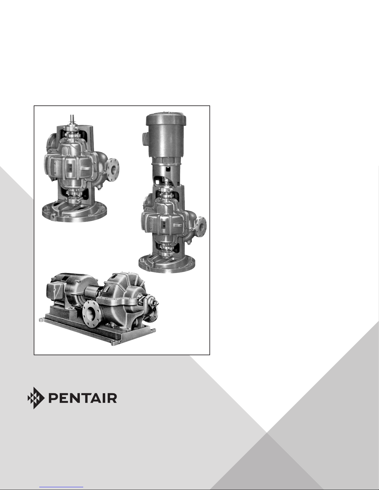
HORIZONTAL
SPLITCASE PUMPS
Model 1940
Model
1900 SERIES
ENGLISH: PAGES 2-36
INSTRUCTION AND REPAIR MANUAL
NOTE! To the installer: Please make sure you
provide this manual to the owner of the equipment or to the responsible party who maintains
the system.
Model 1910
Models 1920 and
1920F
Part #FM-03-529 | © 2018 Pentair plc. | 11/19/18

TABLE OF CONTENTS:
WARRANTY HIGHLIGHTS ...........................................3
INTRODUCTION ..............................................................5
GENERAL ...................................................................5
CAUTION & SAFETY NOTICE .................................. 5–6
PUMP IDENTIFICATION ..............................................6
SAFETY NOTES ...................................................... 6–7
HOUSEKEEPING ......................................................... 7
ENVIRONMENTAL CONDITIONS .................................7
STORAGE OF PUMPS ...................................................... 7
GENERAL ................................................................... 7
CONSIDER A UNIT IN STORAGE .................................. 7
SHORT-TERM STORAGE ........................................8
LONG-TERM STORAGE ..........................................8
THREE MONTHS TO ONE YEAR ..............................8
OVER ONE YEAR ................................................ 8–9
REMOVING FROM STORAGE .......................................9
INSTALLATION ..............................................................9
NET POSITIVE SUCTION HEAD (NPSH) ..................... 10
WET WELL DESIGN .................................................. 10
LOCATION AND HANDLING ................................... 10–11
FOUNDATION ............................................................ 11
LEVELING OF THE UNIT ............................................ 11
GROUTING ............................................................ 11-12
PIPING ...................................................................... 12
INITIAL COUPLING ALIGNMENT ............................... 12
PERIODIC CHECK ..................................................... 13
AUXILIARY PIPING CONNECTIONS ........................... 13
ROTATION ................................................................ 14
OPERATION.................................................................. 14
GENERAL ................................................................. 14
OPERATING AT REDUCED CAPACITY ....................... 14
PRIMING ................................................................... 15
STARTING THE PUMP ............................................... 15
NORMAL OPERATION ...........................................15–16
STOPPING THE PUMP ............................................... 16
NORMAL SHUTDOWN ............................................... 16
EMERGENCY SHUTDOWN ........................................ 16
BEARING OPERATING TEMPERATURE ..................... 16
TROUBLESHOOTING .....................................................17
PUMP ...................................................................17–19
MOTOR ...........................................................20–21
REPAIR MANUAL .........................................................22
SERVICE ......................................................................22
LUBRICATION OF BEARINGS .............................. 22–23
REPAIRS ......................................................................23
DISASSEMBLY OF THE PUMP ............................. 23–25
MECHANICAL SEALS ..................................... 25–26
REASSEMBLY .................................................... 26–27
STANDARD PACKING ........................................... 27
MECHANICAL SEAL ....................................... 27–30
STARTING PUMP AFTER REASSEMBLY .................... 31
ORDERING PARTS ............................................... 31-35
RECOMMENDED SPARE PARTS ................................ 31
PREDICTED LIFE ...................................................... 31
PARTS LIST ..............................................................32
MISCELLANEOUS NUMBERED PARTS ......................32
PUMP EXPLODED VIEWS .................................... 33–35

WARRANTY:
WARRANTY HIGHLIGHTS:
1. Seller warrants products of its own manufacture and workmanship under normal use and service according to
previously submitted terms and conditions letter or form KC585.
2. Accessories and components not manufactured by seller are warranted only to the extent of the original
manufacturer's warranty.
3. No allowances will be made for repairs or alterations effected without specific written authorization from seller.
4. Repairs or alterations made with other than genuine Fairbanks Nijhuis™ original equipment parts may void the
warranty and relieve the seller of all product responsibility.
5. This warranty is void unless the purchaser provides protective storage, installs and maintains the equipment in
accordance with manufacturer's instructions.
6. Under the terms of this warranty, seller shall not be responsible nor liable for:
3
a. Consequential, collateral or special losses or damages.
b. Equipment conditions caused by fair wear and tear, abnormal conditions of use, accident, neglect, or misuse of
said equipment.
c. Labor charges, loss or damage resulting from supplying of defective part(s) or improper repairs by unauthorized
person(s).
d. Damage caused by abrasive materials, chemicals, scale deposits, corrosion, lightning, improper voltage
or mishandling.
7. The above listed warranty highlights do not constitute our total terms and conditions regarding warranty.
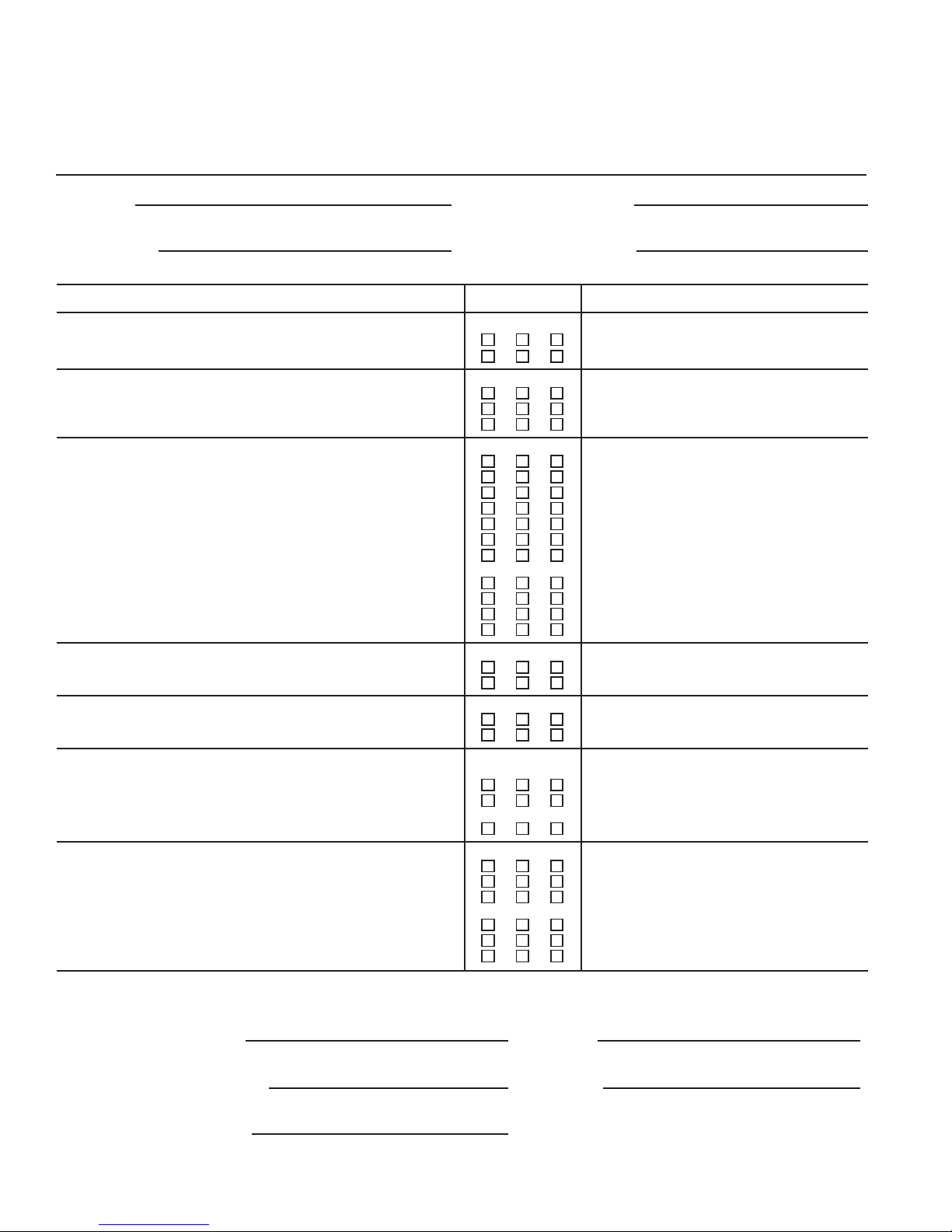
PRESTART-UP AND START-UP CHECK LIST
Contractor Pump Serial Number
Project Name Pump Model Number
Procedure Yes No N/A Comments
1. Shipment
Was there any damage in transit?
Were all items received?
2. Storage
Has equipment been protected from inclement weather?
Was equipment subject to flooding?
Have all bearings been protected from moisture?
3. Installation
Were retaining fasteners, used in shipping, removed prior to installation?
Is grouting under base properly compacted?
Is grouting of the non-shrink type?
Have proper anchor bolts been used?
Have the bolts been properly tightened?
Have both the suction and discharge been checked for pipe strain?
Are lube lines and seal water lines properly installed?
Are accessory items, RTD’s, bearing temp detectors, vibration sensors, etc.
mounted and properly installed?
Are lube lines purged of air and lubricant added? (pump and driver)
Are all safety guards in place?
Have impellers been checked for proper clearance?
4. Alignment
Has the alignment of driver to pump been checked?
Have indicator readings been taken?
5. Rotation
Has the rotation of the drives been checked for correctness?
Has the coupling been turned to assure free rotation of pump and motor?
6. System
Has the system been checked to ensure that it is free ot foreign matter which
could be damaging to the pump?
Is liquid available to the pump?
Has assurance been obtained from responsible parties that all piping is secure
and that the routing of flow has been established and is correct?
7. Start-Up
Has flow been established?
Have gauge readings been taken?
Has packing been adjusted to ensure proper lubrication of packing?
If pumps are equipped with mechanical seals, is the lubricating seal water
pressure a constant 10 to 15 psi above the discharge of the pump?
Is excessive vibration present?
Is bearing operating temperature excessive?
Customer’s Representative
Witnessing Start-Up
Date
Company
Name
Fairbanks Nijhuis™ Pump Corporation
Representative Conducting Start-Up
Date
Name

1900 Series Horizontal Splitcase Pumps
Instruction and Repair Manual
CALIFORNIA PROPOSITION 65 WARNING:
This product and related accessories contain chemicals known to the State of California to cause cancer,
birth defects or other reproductive harm.
INTRODUCTION:
GENERAL:
Congratulations! You are the owner of the finest pump commercially available. If you give it the proper care as outlined
and recommended by this manual, it will provide you with reliable service and long life.
This manual contains information that is the result of engineering and research efforts. It is designed to supply adequate
instructions for the installation, operation and maintenance of your pump. Failure or neglect to properly install, operate
or maintain your pump may result in personal injury, property damage or unnecessary damage to
the pump.
These instructions apply to the pump only and have been prepared specifically for the pump supplied on this order. If your
operating conditions ever change, always refer to the factory for reapplication. Always refer to the manuals provided by
manufacturers of the accessory equipment for their separate instructions.
5
Variations exist in both the equipment used with these pumps and in the particular installation of the pump and driver.
Therefore, specific operating instructions are not within the scope of this manual but should be added by the parties
responsible for the operation of the entire station. The manual contains general rules and guidelines for installation,
operation and maintenance of the pump. If there are questions regarding the pump or its application, which are not
covered in this manual, please contact the factory as follows:
Fairbanks Nijhuis™
3601 Fairbanks Ave.
Kansas City, KS 66106
(913) 371-5000
For information or technical assistance on the drive source, contact the drive manufacturer local dealer or
representative.
To obtain additional data on hydraulics and pump selection and operation, we suggest you purchase both of the following
reference books:
A. Fairbanks Nijhuis Hydraulic Handbook available from the factory.
B. Hydraulic Institute Standards
Hydraulic Institute
9 Sylvan Way
Parsippany, NJ 07054-3802
CAUTION AND SAFETY NOTICE:
The installation, use and operation of this type of equipment is affected by various federal, state and local laws and the
regulations concerning OSHA. Compliance with such laws relating to the proper installation and safe operation of this
type of equipment is the responsibility of the equipment owner, and all necessary steps should be taken by the owner to
assure compliance with such laws before operating the equipment. In addition WARNING and CAUTION notes are located
throughout this manual. They should be read and observed.
The following symbols are used to alert maintenance personnel to procedures that require special attention or which
could damage equipment or could be dangerous to personnel.
11/12/18

6
1900 Series Horizontal Splitcase Pumps
Instruction and Repair Manual
DANGER:
Indicates an imminently hazardous situation which, if not avoided, will result in death or serious injury.
WARNING:
Indicates a potentially hazardous situation which, if not avoided, could result in serious injury.
CAUTION:
Indicates that improper practices will result in equipment malfunction or failure.
NOTES:
Instructions that will aid in installation, operation, maintenance or that clarify a procedure.
PUMP IDENTIFICATION:
Pertinent nameplate information is shown below. It will aid in obtaining the correct replacement parts for your pump. The
serial number is stamped on the discharge flange.
Pump
Serial Number
Model Number
Pump Size
Number Stages
GPM
Head (feet)
*To be copied from motor nameplate.
Speed (RPM)
Driver
Manufacturer
Horsepower
Serial Number*
Full Load Amps
Phase / Hertz / Volts
SAFETY NOTES:
These warnings apply to pumps supplied by Fairbanks Nijhuis™. Refer to the manuals supplied by the driver or control
manufacturers for additional warnings before operating this equipment.
Before attempting to service this pump, familiarize yourself with this manual.
DANGER:
Disconnect or lock out the power source to ensure the pump will not start. Check with appropriate electrical
test equipment.
Do not attempt to service the pump until the electrical power has been disconnected and it has been verified that the
pump cannot start.
Certain procedures in disassembly and assembly require parts be heated to high temperatures. Heat resistant gloves
must be worn when handling heated parts. Heated parts can cause severe personal injury.
After the pump has been installed make certain that the pump and all piping connections are tight and are properly
supported prior to start-up and operation.
WARNING:
CAUTION:
11/12/18

1900 Series Horizontal Splitcase Pumps
Instruction and Repair Manual
WARNING:
Do not operate the pump without the protective guards in place over the rotating parts. Exposed rotating parts can
catch clothing, fingers, or tools, causing severe injury to personnel.
CAUTION:
This pump is designed for the exclusive use of pumping water. It should not be used for pumping other media unless a
specific Purchase/Buyer agreement is negotiated.
WARNING:
Because many installations use automatic starting equipment, the pump unit may start at any time
without warning.
HOUSEKEEPING:
The area surrounding the pump installation area should be kept free of rags and debris. The area should be kept clean and
dry and should be checked periodically to ensure there is no water, oil or grease on the floor which could cause accidental
slippage of maintenance personnel.
7
The pump and driver should be kept clean. Any spillage of lubricants on the pump/driver during periodic maintenance
should be wiped clean. Loose ends of packing should be picked up and properly discarded after repacking the pump.
Drain lines should be checked to ensure they are functioning properly.
Driver ventilation ports should be kept free to ensure proper cooling of the motor.
ENVIRONMENTAL CONDITIONS:
Pumps are designed to operate in moderate to severe environmental conditions. Normally they should not be operated
in an ambient temperature exceeding 130°F or in conditions that would allow the sealing water or the pumped media to
freeze.
STORAGE OF PUMPS;
GENERAL:
If the equipment is not to be immediately installed and operated, store it in a clean, dry, well-ventilated place, free from
vibrations, moisture and rapid or wide variations in temperature.
Improper storage and preservation could damage the equipment which would result in non-warranty covered restoration
requirements or non-warranty covered product failures.
CONSIDER A UNIT IN STORAGE:
1. When it has been delivered to the job site and is awaiting installation.
2. When it has been installed but operation is delayed pending completion of construction.
3. When there are long (30 days or more) periods between operation cycles.
4. When the pump is shut down for periods of longer than 30 days.
11/12/18

8
1900 Series Horizontal Splitcase Pumps
Instruction and Repair Manual
SHORT-TERM STORAGE:
Short-term storage is when the pump will be stored for periods not exceeding three months. The following are the shortterm storage requirements:
A. Rotate the shaft for several revolutions at least once every two weeks to:
1. Coat the bearing with lubricant.
2. Retard oxidation or corrosion.
3. Prevent possible false Brinelling.
LONG-TERM STORAGE:
Long-term storage is when the pump will be stored for periods exceeding three months. The following are long-term
storage requirements:
THREE MONTHS TO ONE YEAR:
1. Remove gland halves, packing and seal water ring from the stuffing box. Package them in a suitable container to
prevent loss or damage. Coat the inside of the stuffing box with grease.
• If the pump is equipped with a mechanical seal, remove the pipe plug in the stuffing box and pour at least 4
ounces of mineral oil into the seal housing. Reinstall the pipe plug.
2. Fill the bearing housings with specified lubricating grease until grease exits from relief fittings.
3. Wipe clean all exposed machined surfaces and coat with a heavy layer of grease or other equivalent rust
prevention material.
4. Cover the suction and discharge of the pump with cardboard or wood to prevent entry of foreign material
or varmints.
5. Rotate the pump shaft several times by hand repeating this every two (2) weeks during storage. Rotation of the
shaft will coat the bearings and retard oxidation, preventing possible false Brinelling.
OVER ONE YEAR:
1. Remove gland halves, packing and seal water ring from the stuffing box. Package them in a suitable container
to prevent loss or damage. Coat the inside of the stuffing box with grease.
• If the pump is equipped with a mechanical seal, remove the pipe plug in the stuffing box and pour at least 4
ounces of mineral oil into the seal housing. Reinstall the pipe plug.
2. Fill the bearing housings with specified lubricating grease until grease exits from relief fittings.
3. Clean all accessible machined surfaces to remove dirt, corrosion, grease and any other foreign matter. Clean
water passages to remove all foreign matter. Dry the pump to remove all moisture.
4. Spray flushing water and seal water piping with P-7 medium preservative oil. Seal all water inlet connections
with pipe caps or plugs.
11/12/18

1900 Series Horizontal Splitcase Pumps
Instruction and Repair Manual
5. All internal surfaces in contact with water should be sprayed with Grade 5 of MIL-C-ISI73 Corrosion Preventive
Compound, solvent cut back. Drain all excess compound by removing drain plugs. Treat the drain plugs with P-I
or P-I9 preservative, replace and tighten.
6. Apply P-2 preservative to all exposed shaft surfaces.
7. Cover inlet and outlet nozzles with Grade A of MIL-B-I21 barrier material and a blank flange of mild steel
(1/16" minimum thickness), tempered hardboard (114" minimum thickness) or fully waterproofed plywood
(114" minimum thickness). Secure the flanges with at least 4 bolts with lockwashers.
8. Wrap the shaft, the frame and the stuffing box area with grease-proof barrier material, conforming to Type I,
Grade A of MIL-B-I2I. Secure the barrier with waterproof pressure sensitive tape.
9. Rotate the pump shaft several times by hand repeating this every two (2) weeks during storage. Rotation of the
shaft will coat the bearings and retard oxidation, preventing possible false Brinelling.
REMOVING FROM STORAGE:
After the storage period is over and prior to operating the pump, remove the cover on the thrust bearing housing for
inspection of the bearing lubricant. If any water or foreign matter is found in the lubricant, all bearings must be cleaned
and the lubricant replaced.
9
Refer to the Installation section of this manual for installation instructions.
After the pump has been set and grouted in place and is ready for operation, the following steps should be followed:
1. Reinstall the packing, seal water ring and gland. Adjust in accordance with this manual. Flush the mineral oil out of
the mechanical seal if unit is so equipped.
2. Remove bearing housing covers and remove one-half of the grease in bearing housings. Remove all grease relief
fittings and grease relief nipples from upper and lower bearing housings.
3. Start the pump per start-up instructions and permit grease to be purged from each bearing housing. Do not install
grease relief piping until purging has completely stopped after the pump has been in operation for at least eight (8)
hours. Observe bearing temperatures, and stop and start the pump or run it at reduced speed until temperatures
stabilize within the specified limits.
4. Stop the pump, wipe any grease off the shaft and bearing frame and place the pump in service per instructions in
this manual.
DANGER:
Do not attempt to clean the pump until electrical power has been disconnected and it has been verified that the pump
cannot start.
INSTALLATION:
Carefully read all sections of this manual and all other instruction manuals provided by manufacturers of other equipment
supplied with this pump.
Upon receipt of the shipment, unpack and inspect the pump and driver assemblies and individual parts to ensure none
are missing or damaged. Carefully inspect all boxes and packing material for loose parts to ensure none are missing or
damaged. Carefully inspect all boxes and packing material for loose parts before discarding them. Report immediately to
the factory, and to the transportation company involved, any missing parts or damage incurred during shipment, and file
your “damaged and/or lost in shipment” claim with the carrier immediately.
11/12/18

10
1900 Series Horizontal Splitcase Pumps
Instruction and Repair Manual
NET POSITIVE SUCTION HEAD (NPSH):
NPSH can be defined as the head (energy) that causes liquid to flow through the suction pipe and enter the eye of the
impeller.
NPSH is expressed in two values:
1. NPSH required (NPSHR).
2. NPSH available (NPSHA).
It is essential that NPSHA always be greater than NPSHR to prevent cavitation, vibration, wear and
unstable operation.
NPSHR is a function of the pump design and therefore varies with the make, size, capacity and speed of the pump. The
value for your pump can be obtained from your pump performance curve or the factory.
NPSHA is a function of your system and may be calculated as follows:
A. When the source of liquid is above the pump:
1. NPSHA = barometric pressure (feet) + static suction head (feet)* – friction losses in suction piping (feet)
– vapor pressure of liquid (feet).
B. When the source of liquid is below the pump:
1. NPSHA = barometric pressure (feet) static suction lift (feet)* – friction losses in suction piping (feet)
– vapor pressure of liquid (feet).
*The datum elevation plane for horizontal pumps is the pump centerline.
WET WELL DESIGN:
Generally, it is required that an evenly distributed flow of non-aerated water be supplied to the pump suction. Improper
wet well or sump design or insufficient suction pipe submergence can result in intake vortexing which reduces the
pump’s performance and can cause severe damage to the pump.
We recommend that you secure the advice of a qualified Consulting Engineer for the analysis and design of the wet well.
Significant engineering data on wet well design is provided in the Hydraulic Institute Standards.
Upon request, Fairbanks Nijhuis™ will review plans and give general comments on the installation, but will not approve
such plans for a specific installation and will accept no responsibility or liability for the performance of the pump
intake structure.
LOCATION AND HANDLING:
The pump should be installed as near the fluid as possible so a short direct suction pipe can be used to keep suction
losses at a minimum. If possible, locate the pump so the fluid will flow to the suction opening by gravity. The discharge
piping should be direct and with as few elbows and fittings as possible. The total net positive suction head available
(NPSHA), which includes the suction lift and pipe friction losses, must be greater than the net positive suction head
required (NPSHR) by the pump.
The pump and driver should be located in an area that will permit periodic inspection and maintenance. Head and access
room should be provided and all units should be installed in a dry location with adequate drainage.
11/12/18
1900 Series Horizontal Splitcase Pumps
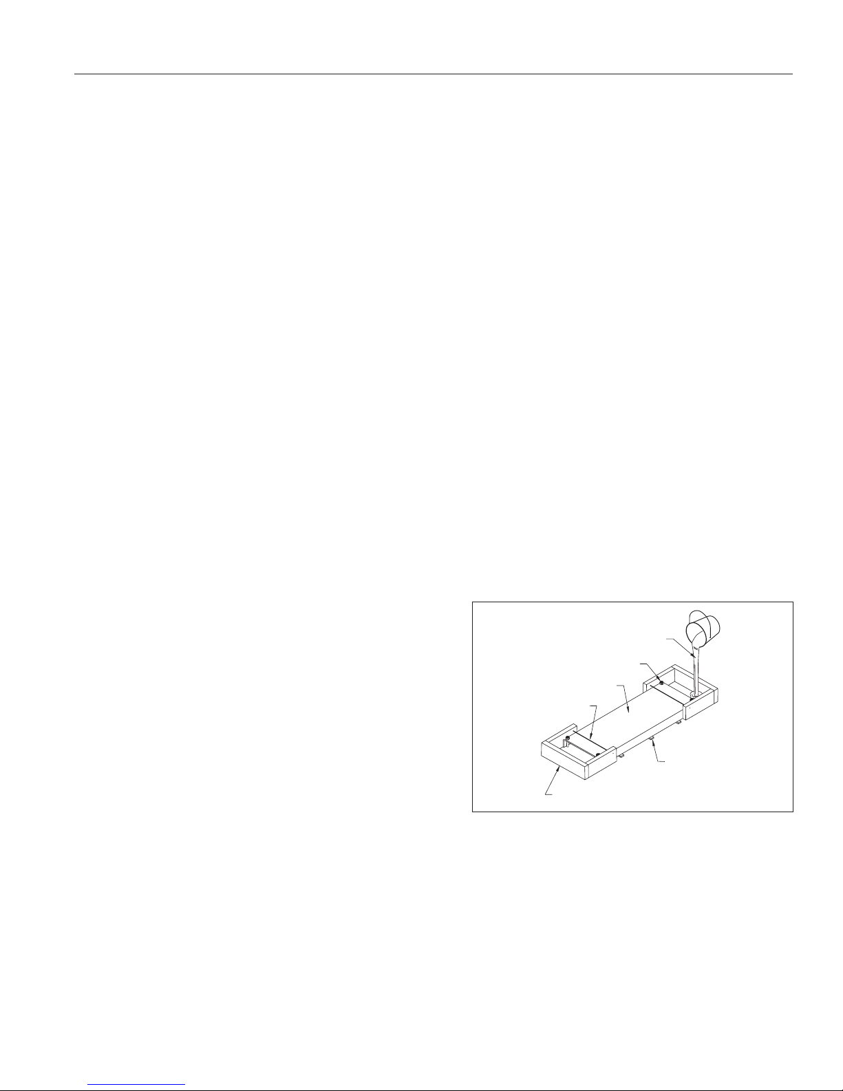
SHIMS TO LEVEL BASE PLATE
WOODEN DAM
ON BOTH ENDS
TWISTED TENSION WIRE
ROLLED STEEL BASE
FOUNDATION BOLTS
SOUPY GROUT
Instruction and Repair Manual
WARNING:
Do not pick up the complete unit by the driver eye bolts or pump shaft.
FOUNDATION:
The pump foundation should have a level surface and be of sufficient mass to prevent vibration and form a permanent
rigid support for the unit. The most satisfactory foundations are concrete with anchor bolts of adequate size embedded
in the foundation in pipe sleeves with an inside diameter 2-1/2 times larger than the bolt diameter. This will allow for final
accurate positioning of the unit.
Recommended anchor bolt design is available from the factory.
LEVELING OF THE UNIT:
Lower the unit onto the foundation and position the base so the anchor bolts are aligned in the middle of the holes in the
base. Disconnect the coupling halves and do not reconnect until all alignment operations are complete.
Set the base on metal shims or metal wedges placed directly under the part of the base carrying the greatest weight, and
spaced close enough to give uniform support and stability.
11
Adjust the metal shims or wedges until the shaft of the pump and driver are level or vertical as appropriate and until pump
and driver shaft are aligned with each other. Make sure that all shims or wedges fit firmly between the foundation and the
base.
If leveling nuts are installed on the anchor bolts and are used for alignment, follow the same procedure as with shims
or wedges. Support the base with additional shims or wedges if necessary. Make sure that all nuts and shims are in firm
contact with the base. Tighten the foundation bolts snugly, but not too firmly, and recheck the shafts for alignment
before grouting.
GROUTING:
IMPORTANT:
The pump base must be set level to avoid any mechanical
difficulties with the pump or motor. The 1900 pump was
properly aligned, if supplied with a motor, at the factory.
However, since the pump base is flexible, it may spring
and twist during shipment. Do not pipe the pump until it is
realigned.
Grouting the base plate prevents lateral movement of the base
plate, and improves the vibration absorbing characteristics of
the foundation by increasing its mass. A wooden dam should be
Figure 1. Grouting the Base for Frame Mounted Pumps.
constructed around the base plate to contain the grout while it is
being poured. The dam can be built tight against the base plate, or slightly removed from it as desired. Refer to Fig. 1. The
entire base plate should be completely filled with nonshrinkable type grout. Be sure to remove all air bubbles from the
grout.
CAUTION:
Damaging vibration may result if the base plate is not solidly in contact with the grout bed.
Do not fill the pipe sleeves with grout.
If leveling nuts are used, make sure they are not embedded in grout. Provide access in the grout to the leveling nuts so
that they can be backed off after the grout has cured.
11/12/18
 Loading...