

Page 1
®
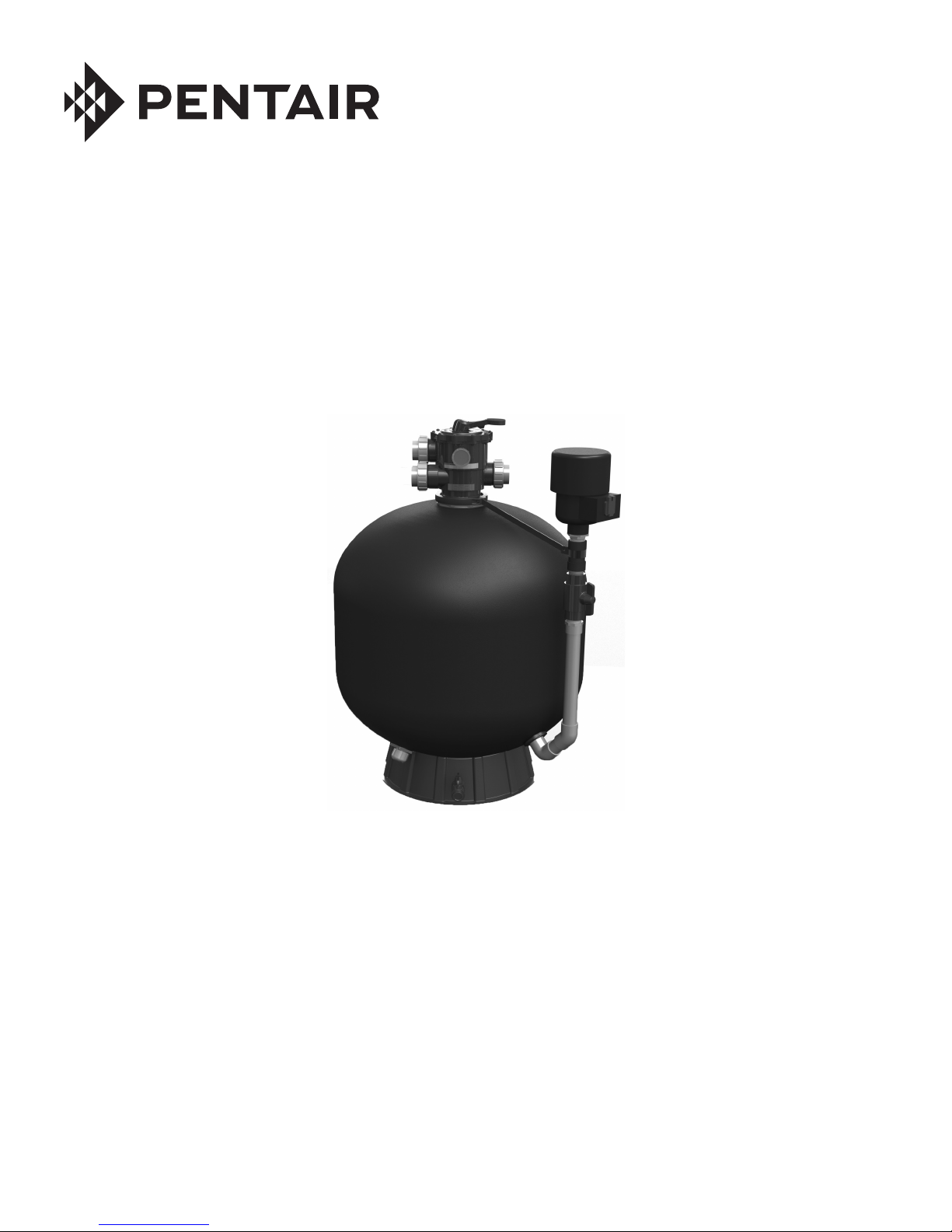
SWEETWATER
BEAD FILTER
MODELS: 165, 330, 495 AND 990
IMPORTANT SAFETY INSTRUCTIONS
READ AND FOLLOW ALL INSTRUCTIONS
SAVE THESE INSTRUCTIONS
INSTALLATION AND
USER’S GUIDE
Page 2

i
CUSTOMER SERVICE / TECHNICAL SUPPORT
If you have questions about ordering Pentair Aquatic Eco-Systems replacement parts and products, please use the
following contact information:
Customer Service
Monday to Thursday: 8 AM to 7 PM EST
Friday: 8 AM to 5 PM EST
US
Phone: (877) 347-4788
FAX: (407) 886-6787
International
Phone: (407) 886-3939
FAX: (407) 886-4884
TABLE OF CONTENTS
Important Warnings and Safety Precautions ....
Installation ............................................................
Introduction
How the Filter Works
Installing the Filter
Initial Start-Up
Maintenance .........................................................
Filter Care
Cleaning Frequency
Filter Backwash Procedure
Web site
Visit www.pentairaes.com
ii
1
1
1
2
3
3
3
4
4
Troubleshooting ..................................................
Replacement Parts ..............................................
5
7
P/N 450001 Rev. A 4/29/16
SWEETWATER® Bead Filter Installation and User’s Guide
Page 3
IMPORTANT WARNING AND SAFETY INSTRUCTIONS
Important Notice:
This guide provides installation and operation instructions for
this product. Consult Pentair with any questions regarding this
equipment.
Attention Installer: This guide contains important information about the
installation, operation and safe use of this product. This information should
be given to the owner and/or operator of this equipment after installation
or left on or near the filter.
Attention User: This manual contains important information that will
help you in operating and maintaining this filter. Please retain it for future
reference.
READ AND FOLLOW ALL INSTRUCTIONS
SAVE THESE INSTRUCTIONS
This is the safety alert symbol. When you see this
symbol on your system or in this manual, look for one of
the following signal words and be alert to the potential
for personal injury.
Warns about hazards that can cause death, serious
personal injury, or major property damage if ignored.
Warns about hazards that may cause death, serious
personal injury, or major property damage if ignored.
Warns about hazards that may or can cause minor
personal injury or property damage if ignored.
NOTE Indicates special instructions not related to hazards.
Carefully read and follow all safety instructions in this manual and on
equipment. Keep safety labels in good condition; replace if missing
or damaged.
Before installing this product, read and follow all
warning notices and instructions which are included.
Failure to follow safety warnings and instructions can result in severe
injury, death, or property damage. Call US: (877) 347-4788 - INT: (407)
886-3939 for additional free copies of these instructions.
Consumer Information and Safety
This filter is designed and manufactured to provide many years of safe
and reliable service when installed, operated and maintained according
to the information in this manual and the installation codes referred to in
later sections. Throughout the manual, safety warnings and cautions are
identified by the “ ” symbol. Be sure to read and comply with all of the
warnings and cautions.
Do not operate the filter until you have read and
understand clearly all the operating instructions and
warning messages for all equipment that is a part of the circulating system.
The following instructions are intended as a guide for initially operating
the filter in a general installation, however each installation may have
unique conditions where the starting procedure could be different. Failure
to follow all operating instructions and warning messages can result in
severe injury, death, or property damage.
Do not permit children to use or operate this filter.
ii
FILTER OPERATES UNDER HIGH PRESSURE.
When any part of the circulating system, (e.g., clamp,
pump, filter, valve(s), etc.), is serviced, air can enter
the system and become pressurized. Pressurized
air can cause the lid to separate which can result in
severe injury, death, or property damage.
To avoid this potential hazard, follow these instructions:
1. Before repositioning valve(s) and before beginning the assembly,
disassembly, or adjustment of the clamp or any other service of the
circulating system: (A) Turn the pump OFF and shut OFF any automatic
controls to ensure the system is NOT inadvertently started during the
servicing; (B) open the manual air relief valve; (C) stand clear of the
filter; (D) wait until all pressure is relieved.
2. Whenever installing the filter clamp FOLLOW THE FILTER CLAMP
INSTALLATION INSTRUCTIONS EXACTLY.
3. Once service on the circulating system is complete FOLLOW SYSTEM
RESTART INSTRUCTIONS EXACTLY.
4. Maintain circulation system properly. Replace worn or damaged parts
immediately, (e.g., clamp, pressure gauge, valve(s), o-rings, etc).
5. Be sure that the filter is properly mounted and positioned according
to instructions provided.
Due to the potential risk that can be involved it is
recommended that the pressure test be kept to
the minimum time required by the local code. Do
not allow people to work around the system when
the circulation system is under pressure test. Post
appropriate warning signs and establish a barrier around the pressurized
equipment. If the equipment is located in an equipment room, lock the
door and post a warning sign.
Never attempt to adjust any closures or lids or attempt to remove or
tighten bolts when the system is pressurized. These actions can result in
a separation or failure of system components. This instantaneous release
of energy can cause components to be accelerated to high velocities and
to travel far distances. These components could cause severe personal
injury or death if they were to strike a person.
Never exceed the maximum operating pressure of
the system components. Exceeding these limits
could result in a component failing under pressure.
This instantaneous release of energy can cause the
closure to separate and could cause severe personal
injury or death if they were to strike a person.
RISK OF ELECTRICAL SHOCK OR
ELECTROCUTION. This filter must be installed
by a qualified service professional in
accordance with the current National
Electrical Code and all applicable local
codes and ordinances. Always disconnect power to the equipment
at the circuit breaker before servicing any of the equipment. Ensure that
the disconnected circuit is locked out or properly tagged so that it cannot
be switched on while you are working on the equipment. Failure to do so
could result in serious injury or death to serviceman, equipment users or
others due to electric shock. Position the filter and the air relief valve to safely
direct water drainage and purged air or water. Water discharged from an
improperly positioned filter or valve can create an electrical hazard that can
cause severe personal injury as well as damage property.
SWEETWATER® Bead Filter Installation and User’s Guide
Page 4
iii
IMPORTANT WARNING AND SAFETY INSTRUCTIONS
This filter is intended for use in aquaculture
installations ONLY. Do not use with any type of
swimming pool, hot tub, or spa.
SERIOUS BODILY INJURY OR DEATH CAN
RESULT IF THIS FILTER IS NOT INSTALLED AND
USED CORRECTLY.
INSTALLERS, OPERATORS AND OWNERS
MUST READ THESE WARNINGS AND ALL
INSTRUCTIONS BEFORE USING THIS FILTER.
HAZARDOUS PRESSURE: STAND CLEAR OF
PUMP AND FILTER DURING START UP
Circulation systems operate under high pressure.
When any part of the circulating system (i.e.
locking ring, pump, filter, valves, etc.) is serviced,
air can enter the system and become pressurized.
Pressurized air can cause the pump housing cover filter lid and valves
to violently separate which can result in severe personal injury or death.
Filter tank lid and strainer cover must be properly secured to prevent
violent separation. Stand clear of all circulation system equipment when
turning on or starting up pump.
Before servicing equipment, make note of the filter pressure. Be sure
that all controls are set to ensure the system cannot inadvertently start
during service. Turn off all power to the pump. IMPORTANT: Place filter
manual air relief valve in the open position and wait for all pressure
in the system to be relieved.
Before starting the system, fully open the manual air relief valve and place
all system valves in the “open” position to allow water to flow freely from the
tank and back to the tank. Stand clear of all equipment and start the pump.
IMPORTANT: Do not close filter manual air relief valve until all
pressure has been discharged from the valve and a steady stream
of water appears. Observe filter pressure gauge and be sure it is not
higher than the pre-service condition.
General Installation Information
The following information should be read carefully since it outlines the
proper manner of care and operation for your filter system.
You can expect maximum efficiency and life from your filtration system by
following these instructions and taking the necessary preventative care.
• Have a trained professional perform all pressure tests.
• Do not connect the system to a high pressure or city water system.
• Trapped air in the system can create a hazardous condition. BE SURE
to purge all air from the system before operating or testing equipment.
• DO NOT pressure test with compressed air!
• Piping must conform to local/state plumbing and sanitary codes.
• Support piping independently to prevent strains on filter or valve.
• Fittings restrict flow; for best efficiency, use the fewest possible fittings.
• A check valve installed ahead of the filter inlet will prevent contaminants
from draining back into the system.
• A check valve installed between the filter and heater will prevent
hot water from backing up into the filter and deforming the internal
components.
• All wiring, grounding and bonding of associated equipment must meet
current local and/or National Electrical Code standards.
Only a qualified plumbing professional should install this filter. Refer to the
“Important Warning and Safety Instructions on pages ii-iii for installation
and safety information.
SAVE THESE INSTRUCTIONS
For Installation of Electrical Controls at Equipment Pad (ON/OFF
Switches, Timers and Automation Load Center)
Install all electrical controls at equipment pad, such
as on/off switches, timers, and control systems,
etc. to allow the operation (startup, shut-down, or
servicing) of any pump or filter so the user does
not place any portion of his/her body over or near
the pump strainer lid, filter lid or valve closures.
This installation should allow the user enough space to stand clear of
the filter and pump during system start-up, shut down or servicing of the
system filter.
SWEETWATER® Bead Filter Installation and User’s Guide
Page 5

1
INSTALLATION
Note: Before installing this product, read and follow all warning notices and instructions on pages
ii-iii.
Only a qualified service person should install the filter. This filter is designed and intended for use in aquaculture
installations ONLY. Do not use with any type of swimming pool, hot tub, or spa.
Introduction
The following general information describes how to install the Sweetwater® Bead Filter. This filter operates
under pressure and if assembled improperly or operated with air in the water circulation system, the valve can
separate from the filter and result in an accident causing property damage or serious bodily injury. Warning
labels have been affixed to the control valve and vessel body and should not be removed. Keep safety labels
in good condition and replace if missing or illegible.
How the Filter Works
Sweetwater up-flow bead filters are used for mechanical and biological filtration in recirculating aquaculture
systems. A bed of floating plastic bead media catches solid debris in the water column as water flows up
through the media.
Beneficial bacteria grow on the plastic beads, feeding on the ammonia produced by the fish being raised in
the system tanks. These bacteria then turn the ammonia into nitrate, a much less toxic molecule for the fish.
The bacteria colonies also provide a sticky layer on the bead media to help trap superfine solids suspended
in the water column, adding an additional component to the mechanical filtration of the bead filter.
During backwash, the bead media is heavily agitated by blowing air into the filter vessel, allowing solids to be
sloughed off the beads and then be rinsed away to waste. This action also serves to remove dead and excess
bacteria from the bead media, preventing detrimental bacteria colonies from over-running the beneficial bacteria.
Table 1: General Filter Data
PART # MODEL
930080
930081
930082
930083
Sweetwater
165
Sweetwater
330
Sweetwater
495
Sweetwater
990
Inlet/Outlet
Size
2" (1-1/2") 4,000/15.1 75/34 1.65 19" x 38" 40-60
2" 8,000/30.3 165/75 3.30 24" x 43" 75-100
2" 12,000/45.4 240/110 4.95 30" x 48" 90-110
2" 24,000/90.9 480/220 9.90 36" x 52" 100-125
Max. System
Size (Gal/m3)
Fish
Supported
(lbs/kg)
Media Capacity
(ft3)
Dimensions
(diameter x height)
Recommended
Flow Rate
(GPM)
SWEETWATER
®
Bead Filter Installation and User’s Guide
Page 6

2
Installing the Filter
Filters should never be tested or subjected to air or gas under pressure. All gases are compressible and under pressure
create a danger. Severe bodily injury or property damage could occur if the filter is subjected to air or gas pressure.
Removing the Control Valve:
1. Depending on your model of Sweetwater
®
Bead Filter, there are two
different valve clamps that can be included with the filter (see Figure 1
or Figure 2). The Sweetwater 165 and 330 include the clamp shown
in Figure 1, while the Sweetwater 495 and 990 include the band
clamp shown in Figure 2.
2. Follow the clamp installation and removal procedures covered in
provided valve manual to install and remove the control valve.
Plumbing the Filter (see Figure 3):
3. Plumb the line coming from the outlet of the pump into the port
marked "PUMP" on the valve head.
4. Plumb the port marked "RETURN" to the downstream flow
returning to the body of water.
5. Plumb the port marked "WASTE" to your waste management
or treatment system.
6. The sludge drain valve can be found in the foot of the tank.
Plumb the sludge drain valve to your waste management or
treatment system.
Note: It is recommended that clear
tubing/piping be used for the sludge drain
connection.
“PUMP PORT”
Valve Clamp
Screw
Figure 2
Figure 1
Valve Clamp
Screws (qty 2)
Filling the Tank with Media:
“WASTE” PORT
Note: The filter should be installed and
plumbed in its final position before adding any
media.
Figure 3
7. Fill the filter 30-50% full of water and
introduce the appropriate amount of floating bead
media, according to Table 2.
8. Place the valve head assembly on the tank vessel
and tighten the valve clamps.
Note: Be sure to reinstall the stainless steel blower
assembly support bar.
This filter operates under pressure. Air can
enter the filter if the valve is not clamped
correctly. This can cause the valve to separate
from the filter, which could cause serious
personal injury and/or property damage.
Table 2: Bead Media Capacity
Filter Part # Model Media Capacity (ft3)
930080
930081
930082
930083
Sweetwater
Sweetwater
Sweetwater
Sweetwater
Electrical Connection:
9. Connect 115VAC, 60Hz power to the air blower.
10. The filter is now ready for operation. Continue to Initial Start-up, on next page.
165
330
495
990
“RETURN” PORT
1.65
3.30
4.95
9.90
SWEETWATER® Bead Filter Installation and User’s Guide
Page 7

Initial Start-up
1. Ensure the return line is open so that water is free to come from the body of water and flow out the
return line.
2. Check pump strainer pot to be sure it is full of water.
Air entering an improperly installed filter can cause the valve to separate from the tank and could cause severe
bodily injury and/or property damage.
3. Check the valve clamp on filter for tightness.
4. Set the control valve to the OPEN position. Stand clear of the filter and start the pump.
Note: Bead media is typically pre-washed and should not require extensive backwashing. However,
the shipping process may cause excessive abrasion which could require an extended backwash cycle
at initial start-up; continue to backwash until the backwash water is as clear as the body of water. See
Filter Backwash Procedure on page 5 for backwash instructions.
To prevent equipment damage and possible injury, always turn the pump off before changing the valve position.
5. Stop the pump once all air has been removed from the system and a steady stream of water appears.
Set the valve to the FILTER position.
6. Ensure all suction and return lines are open so that water is free to come from the body of water and
return to the body of water.
3
7. Stand clear of the filter and start the pump.
8. The filter has now started its filtering cycle. You should ensure that water is returning to the body of
water and take note of the operating pressure when the filter is clean.
MAINTENANCE
This section describes how to maintain your Sweetwater® Bead Filter.
Filter Care
The filter is a very important part of the system equipment and installation. Proper care and maintenance will
add many years of service. Follow these suggestions for long, trouble-free operation:
1. To clean the exterior of the filter of dust and dirt, wash with a mild detergent and water then hose off. Do
not use solvents.
2. If internal maintenance is required, media may be removed by removing the drain from the bottom of the
filter and flushing with a garden hose.
3. If after a number of years, the filter tank appears foggy in color or rough in texture, the tank surface can
be painted. We recommend the use of a Quick Dry Spray Enamel. DO NOT paint the valve.
Always visually inspect filter components during normal servicing to ensure structural safety. Replace any item
which is cracked, deformed or otherwise visually defective. Defective filter components can allow the filter top or
attachments to separate and could cause severe bodily injury or property damage.
4. The control valve on your filter was manufactured with high quality corrosion resistant materials. This part
should be carefully inspected whenever servicing your filter. If excessive leakage is noted coming from
the valve/tank interface, the valve and o-ring should be carefully inspected and replaced if any signs of
deterioration exist.
5. Your filter is a pressure vessel and should never be serviced while under pressure. Always relieve tank
pressure and set the control valve to the OPEN position before attempting to service your filter.
SWEETWATER
®
Bead Filter Installation and User’s Guide
Page 8

4
Cleaning Frequency
1. A newly installed filter should be backwashed and thoroughly cleaned before being placed into service.
This will clean out packaging and/or construction debris.
2. The bead filter should be backwashed regularly to prevent build-up of solid debris, which promotes
heterotrophic bacteria (non-beneficial) to grow and stifle the efficacy of the beneficial bacteria in the filter.
It is recommended to backwash the filter approximately once per week, with exact frequency based upon
pressure drop across the filter. The maximum pressure build-up is 10 PSI. This pressure build-up is when
the filter gauge reading increases 10 PSI over the initial (clean filter) reading. This pressure build-up is
largely based upon the amount of solids filtration the bead filter is performing.
3. It is important not to backwash the filter too frequently as each backwash disrupts the growth of beneficial
bacterial colonies in the filter. Backwash the filter at regular intervals, depending on the pressure build-up
in the filter, to maintain steady system performance.
4. The bead filter should be backwashed no less frequently than once every other week during system
operation. This minimum backwash schedule is to break up the beneficial (and non-beneficial) bacterial
growth on the bead media to eliminate any water flow channeling and to wash away dead bacteria that
impede maximum filter efficiency.
Filter Backwash Procedure
To prevent equipment damage and possible injury, always turn the pump off before changing the valve position.
1. Stop the pump.
2. Ensure that the suction and return lines are open so that water is free to come from the body of water
and flow out the return line. Set control valve to RECIRCULATE position.
3. Open the ball valve on the external air blower piping.
4. Turn on the air blower and allow the blower to agitate the bead
media for one minute.
5. Turn off the blower and close the blower ball valve.
6. Set the control valve to the BACKWASH position and turn on the
pump.
7. Allow the pump to run until the water exiting the waste port runs
clear, or a minimum of one minute. Turn the pump off.
Air Blower
Ball Valve
8. For light-duty aquaculture: You may return the filter to FILTER
mode, and turn on the pump. With the pump running, slowly open
the sludge drain valve and allow heavy solids that have collected
Sludge
Drain Valve
in the bottom of the filter to drain to waste. Close the sludge drain
when water runs clean, or after one minute.
Note: It is possible to drain bead media through the sludge drain. Be careful to not accidentally drain a
significant quantity of media during this operation.
9. For heavier-duty aquaculture: Your system may benefit from an additional round of bead agitation and
backwashing. Repeat steps 2-7 as needed.
10. The filter has now started its filtering cycle. You should ensure that water is returning to the body of
water and take note of the filter pressure.
SWEETWATER® Bead Filter Installation and User’s Guide
Page 9

TROUBLESHOOTING
Use the following troubleshooting information to resolve possible problems with your Sweetwater® Bead Filter.
THIS FILTER OPERATES UNDER HIGH PRESSURE
When any part of the circulating system, (e.g., closure, pump, filter, valve(s), etc.), is serviced, air can enter the system
and become pressurized. Pressurized air can cause the valve to separate from the filter which can result in severe injury,
death, or property damage. To avoid this potential hazard, follow these instructions:
1. If you are not familiar with your filtration system and/or heater:
a. Do NOT attempt to adjust or service without consulting your dealer, or a qualified technician.
b. Read the entire Installation & User’s Guide before attempting to use, service or adjust the filtration system
or heater.
2. Before repositioning valve(s) and before beginning the assembly, disassembly, or any other service of the
circulating system: (A) Turn the pump OFF and shut OFF any automatic controls to ensure the system is
NOT inadvertently started during the servicing; (B) set the control valve to the OPEN position; (C) wait until all
pressure is relieved.
3. Whenever installing the filter valve FOLLOW THE FILTER VALVE WARNINGS EXACTLY.
4. Once service on the circulating system is complete FOLLOW INITIAL START-UP INSTRUCTIONS EXACTLY.
5. Maintain circulation system properly. Replace worn or damaged parts immediately, (e.g., closure, pressure
gauge, valve(s), o-rings, etc).
6. Be sure that the filter is properly mounted and positioned according to instructions provided.
5
PROBLEM CAUSE REMEDY
Body of water not
sufficiently clean
High filter pressure 1. Insufficient backwashing
Short cycles 1. Improper backwash
1. Poor super-fines filtration
2. Inadequate turnover rate
3. Wrong media size
2. Media bed plugged
3. Partially closed valve
2. Mechanical filtration load too high
3. Media bed plugged
4. Foreign growth inside filter
Reduce backwash frequency to allow bacterial
colonies to develop fully.
Increase flow rate (reduce restrictions, increase
pumping capacity).
Use only media matching that supplied with the filter.
Replacement media available through Pentair.
Backwash until effluent runs clear, may require
additional backwash cycles.
Remove valve head and physically agitate bead
media to break up large clumps of media; backwash
thoroughly.
Open valve or remove obstruction in return line.
Backwash until effluent runs clear.
Recommended addition of primary mechanical filter
upstream of the bead filter.
Remove valve head and physically agitate bead
media to break up large clumps of media; backwash
thoroughly.
Remove bead media and chemically clean filter to
eradicate growth. Clean bead media or replace with
new media.
Return flow to body
of water diminished,
low filter pressure
1. Obstruction in pump strainer
2. Obstruction in pump
3. Obstruction in suction line of pump
Clean basket in pump strainer.
Disassemble and clean pump.
Remove obstruction in lines, open valves in suction
line.
SWEETWATER
®
Bead Filter Installation and User’s Guide
Page 10

6
Troubleshooting, (Cont.)
PROBLEM CAUSE REMEDY
Media returning to
body of water
Media loss to waste 1. Broken media strainer
Leak at valve 1. Improperly tightened valve clamp
Poor water quality
(high ammonia and/
or nitrite)
1. Broken media strainer
2. Broken or damaged valve head
screen
2. Wrong Media Size
2. Dirt of contamination on sealing
surface
3. Damaged part
1. Insufficient beneficial bacteria
2. Insufficient bead media
3. High biological load
4. Excessive heterotrophic bacteria
(detrimental)
Replace broken or damaged strainer.
Replace control valve head assembly.
Replace broken or damaged strainer.
Change to proper media.
Shut off pump, relieve tank pressure, tighten valve
clamp properly.
Shut off pump, relieve tank pressure, remove valve
and clean all sealing surfaces. Reassembly valve
properly.
Same as above except replace damaged o-ring,
valve, tank, or any combination of parts as required.
Modify water chemistry to promote bacterial growth;
Add bacterial booster (ProLine Baquaculture
Bacteria Concentrate, or similar) to filter; reduce
excessive backwash frequency (or increase
frequency if backwash cycles are fewer than once
every two weeks).
Add bead media to replenish media to proper
volume.
Decrease fish load and/or feed rate, or supplement
system with additional biological filtration.
Noted by excessively slimy surfaces/bead media,
increase backwash frequency and mechanical
filtration load to inhibit growth of heterotrophic
bacteria.
SWEETWATER® Bead Filter Installation and User’s Guide
Page 11

REPLACEMENT PARTS
VALVE ASSEMBLY FOR
SWEETWATER BEAD FILTER
MODELS 165 AND 330
3
2
4
5
10
9
8
7
2*
11*
3x
12*
13*
6**
1**
6**
1**
7
Item # P/N Description
930080 930081 930082 930083
Used On:
1 930138 Valve Head, Replacement for 930080 1 - - -
1 930139 Valve Head, Replacement for 930081 - 1 - -
1 930140 Valve Head, Replacement for 930082 - - 1 -
1 930141 Valve Head, Replacement for 930083 - - - 1
2* 190059-AQ Pressure Gauge w/Indicator Bezel 1 1 1 1
3 457020S Union, 2" Sch40 PVC, Soc X Soc 1 1 3 3
4 275333-AQ O-Ring, Valve Body, 3/16" - - 1 1
5 152130-AQ Clamp, Valve Head - - 1 1
6** 270561 Strainer, 2" Mipt 1 1 1 1
7 930135 Blower, 1HP 110V/60Hz 1 1 - -
7 930137 Blower, 1.5HP 115V/60Hz - - 1 1
8 CV485 Check Valve, 1-1/2" w/ Spring 1 1 1 1
9 1071015 Ball Valve, 1-1/2" Threaded 1 1 1 1
10 1071007 Ball Valve, 3/4" Threaded 1 1 1 1
11* 2" Hybrid Valve Union Adapter Set 3 3 - -
12* 2" Hybrid Valve Clamp Set 1 1 - -
13* 2" Hybrid Valve Body O-Ring 1 1 - -
* 272569-AQ Hybrid Valve, Replacement Kit 1 1 - -
Note (*): These items are included with Item #14 (P/N 272569-AQ). Item #2 (P/N 190059-AQ) is also available separately.
Note (**): Item #6 is included with your filter's valve head, but can also be purchased separately.
SWEETWATER
®
Bead Filter Installation and User’s Guide
Page 12

2395 APOPKA BLVD., APOPKA, FL 32703 • US (877) 347-4788 • INT. (407) 886-3939
WWW.PENTAIRAES.COM
All Pentair trademarks and logos are owned by Pentair or one of its global affiliates. Pentair Aquatic Eco-Systems® and Sweetwater® are registered
trademarks of Pentair Aquatic Eco-Systems and/or its affiliated companies in the United States and/ or other countries. Unless expressly noted,
names and brands of third parties that may be used in this document are not used to indicate an affiliation or endorsement between the owners
of these names and brands and Pentair Aquatic Eco-Systems. Those names and brands may be the trademarks or registered trademarks of those
third parties. Because we are continuously improving our products and services, Pentair reserves the right to change specifications without prior
notice. Pentair is an equal opportunity employer.
© 2016 Pentair Aquatic Eco-Systems, Inc. All rights reserved. This document is subject to change without notice.
P/N 450001 REV. A 4/29/16
 Loading...