

Pentair BERKELEY HL Series, BERKELEY SL Series, 5SL, 5HL, 7HL Owner's Manual
...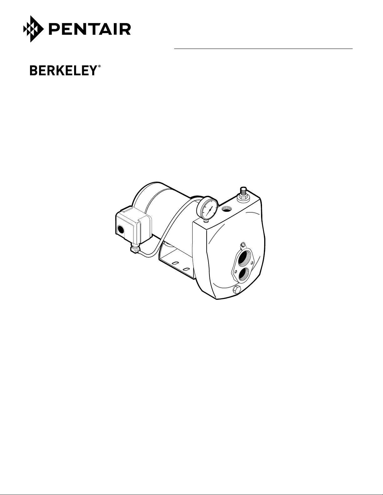
OWNER’S MANUAL
Convertible Deep Well Jet Pumps
60
40
80
20
100
“HL” and “SL” Series
Installation/Operation/Parts
For further operating, installation, or maintenance assistance:
Call 1-800-782-7483
293 WRIGHT STREET, DELAVAN, WI 53115 WWW.BERKELEYPUMPS.COM
PH: 888-782-7483
© 2013 Pentair, Ltd. All Rights Reserved. BE423 (Rev. 02/25/13)
Safety 2
READ AND FOLLOW
SAFETY INSTRUCTIONS!
This is the safety alert symbol. When you see this
symbol on your pump or in this manual, look for
one of the following signal words and be alert to the
potential for personal injury:
warns about hazards that will cause seri-
ous personal injury, death or major property damage if
ignored.
ous personal injury, death or major property damage if
ignored.
minor personal injury or property damage if ignored.
The label NOTICE indicates special instructions which
are important but not related to hazards.
Carefully read and follow all safety instructions in this
manual and on pump.
Keep safety labels in good condition.
Replace missing or damaged safety labels.
California Proposition 65 Warning
tain chemicals known to the State of California to cause
cancer, birth defects or other reproductive harm.
warns about hazards that can cause seri-
warns about hazards that will or can cause
This product and related accessories con-
ELECTRICAL SAFETY
Capacitor voltage may be hazardous.
To discharge motor capacitor, hold insulated handle
screwdriver BY THE HANDLE and short capacitor terminals together. Do not touch metal screwdriver blade
or capacitor terminals. If in doubt, consult a qualified
electrician.
GENERAL SAFETY
Do not touch an operating motor. Modern
motors can operate at high temperatures. To avoid burns
when servicing pump, allow it to cool for 20 minutes
after shut-down before handling.
Do not allow pump or any system component to freeze.
To do so will void warranty.
Pump water only with this pump.
Periodically inspect pump and system components.
Wear safety glasses at all times when working on pumps.
Keep work area clean, uncluttered and properly lighted;
store properly all unused tools and equipment.
Keep visitors at a safe distance from the work areas.
Pump body may explode if used as a
booster pump unless relief valve capable of passing full
pump flow at 100 psi is installed.
WARNING
Hazardous voltage.
Can shock, burn, or
cause death.
Ground pump before
connecting to power
supply. Disconnect power
before working on pump,
motor or tank.
Wire motor for correct
voltage. See
“Electrical” section of
this manual and motor
nameplate.
Ground motor before
connecting to power
supply.
Meet National
Electrical Code,
Canadian Elec tri cal
Code, and local codes
for all wiring.
Follow wiring
instructions in this
manual when
connecting motor to
power lines.
WARNING
Hazardous pressure!
Install pressure relief
valve in discharge pipe.
Release all pressure on
system before working on
any component.

Table of Contents 3
Page
General Safety .....................................................................................................2
Warranty..............................................................................................................3
Typical Installations .............................................................................................4
Discharge Pipe and Pressure Tank Connections ..................................................5
Electrical ..........................................................................................................6, 7
Preparing To Start The Pump – Deep Well ..........................................................8
Preparing To Start The Pump – Shallow Well .....................................................9
Repair Parts .................................................................................................10,11
Troubleshooting ................................................................................................. 12
Performance ................................................................................................13, 14
Limited Warranty
BERKELEY warrants to the original consumer purchaser (“Purchaser” or “You”) of the products listed below, that they will be free
from defects in material and workmanship for the Warranty Period shown below.
Product Warranty Period
Water Systems:
Water Systems Products — jet pumps, small centrifugal pumps, submersible pumps and
related accessories
Pro-Source™
Pro-Source™ Steel Pressure Tanks 5 years from date of original installation
Pro-Source™ Epoxy-Lined Tanks 3 years from date of original installation
Sump/Sewage/Effluent Products
Agricultural/Commer
Centrifugals – close-coupled motor drive, frame mount, SAE mount, engine drive, VMS, SSCX,
SSHM, solids handling, submersible solids handling
Submersible T
Our limited warranty will not apply to any product that, in our sole judgement, has been subject to negligence, misapplication,
improper installation, or improper maintenance. Without limiting the foregoing, operating a three phase motor with single phase
power through a phase converter will void the warranty. Note also that three phase motors must be protected by three-leg,
ambient compensated, extra-quick trip overload relays of the recommended size or the warranty is void.
Your only remedy, and BERKELEY’s only duty, is that BERKELEY repair or replace defective products (at BERKELEY’s choice). You
must pay all labor and shipping charges associated with this warranty and must request warranty service through the installing
dealer as soon as a problem is discovered. No request for service will be accepted if received after the Warranty Period has
expired. This warranty is not transferable.
BERKELEY SHALL NOT BE LIABLE FOR ANY CONSEQUENTIAL, INCIDENTAL, OR CONTINGENT DAMAGES WHATSOEVER.
THE FOREGOING LIMITED WARRANTIES ARE EXCLUSIVE AND IN LIEU OF ALL OTHER EXPRESS AND IMPLIED WARRANTIES,
INCLUDING BUT NOT LIMITED TO IMPLIED WARRANTIES OF MERCHANTABILITY AND FITNESS FOR A PARTICULAR
PURPOSE. THE FOREGOING LIMITED WARRANTIES SHALL NOT EXTEND BEYOND THE DURATION PROVIDED HEREIN.
Some states do not allow the exclusion or limitation of incidental or consequential damages or limitations on the duration of an
implied warranty, so the above limitations or exclusions may not apply to You. This warranty gives You specific legal rights and You
may also have other rights which vary from state to state.
This Limited Warranty is effective June 1, 2011 and replaces all undated warranties and warranties dated before June 1, 2011.
Composite Tanks 5 years from date of original installation
cial:
urbines, 6” diameter and larger
whichever occurs first:
12 months from date of original installation, or
18 months from date of manufacture
12 months from date of original installation, or
18 months from date of manufacture
12 months from date of original installation, or
24 months from date of manufacture
12 months from date of original installation, or
24 months from date of manufacture
In the U.S.: BERKELEY, 293 Wright St., Delavan, WI 53115
In Canada: 269 Trillium Dr., Kitchener, Ontario N2G 4W5
Piping omitted
1799 0497
n
1800 0497
1903 0497
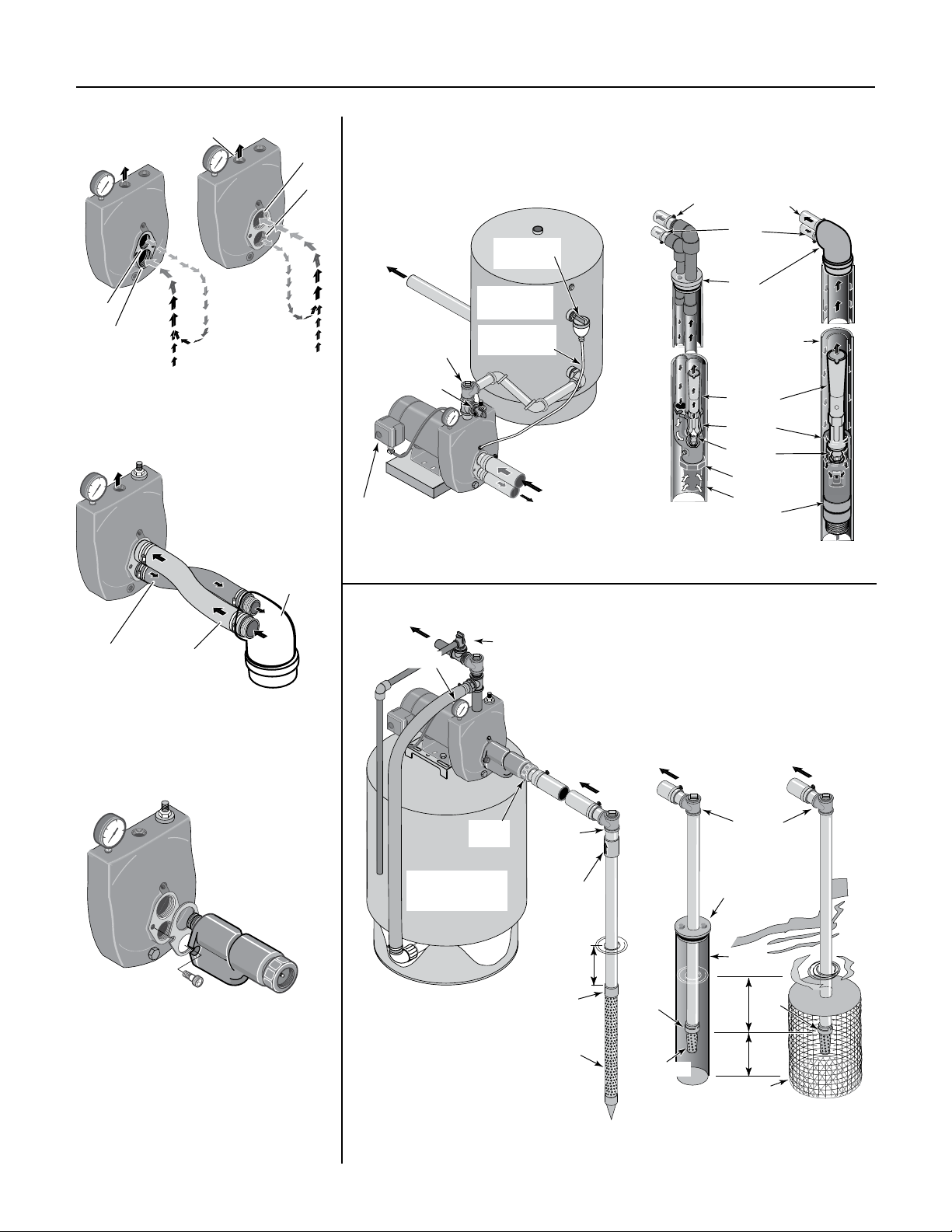
Typical Installations 4
)
To Household
Pressure Gauge
for clarity
40
20
Drive
over
Suction
60
80
100
Discharge
60
40
80
20
100
Drive Pipe
sends water
down the well
to
drive water
up through the
Suction Pipe
to Pump Suction
Suctio
over
Drive
Figure 1: Drive and Suction Functions
60
40
80
20
100
If well head and pump
don't match, twist
reinforced flexible pipe
to connect drive
and suction pipes.
Well
Head
To Household
Water System
Air Volume
Control
Standard
Tank
60
40
80
20
100
Drive Pipe
To Well
Air Volume
Control Tube
Suction Pipe
From Well
Relief Valve
Pressure
Switch
Priming Tee
and Plug
Figure 4: Typical Deep Well Installations
"Double Pipe"
(4" and Larger
Diameter Well)
Suction (Larger)
Pipe from Well
"Single Pipe"
(2" and 3"
Diameter Well
Drive
(Smaller)
Pipe to
Well
Well
Head
Well Casing
serves as
Drive Pipe
Venturi
Ejector
Nozzle
Foot Valve
Strainer
Leather
Cup Seals
24
J32P-
JET NO.
41
1834 0695
Drive
Pipe
Suction
Pipe
Figure 2: Reversed Connections
to Well
60
40
80
20
100
Figure 3: Mount Ejector –
Shallow Well
Water System
60
40
80
20
100
Check
Valve
Pre-charged
Precharged
Tank
Tank
Not
to
Scale
Relief Valve
Priming
Tee and
Plug
Drive point
below water
level
Drive
Point
Check
Valve
Drive
Coupling
Drive
Point
Cased
Well
Foot
Valve
Strainer
Suction Pipe
From Well
Priming
Tee and
Plug
Sanitary
Well Seal
Well
Casing
Foot
10'
Min.
Valve
5–10'
Screen
Open
Water
1836 0695
Figure 5: Typical Shallow Well Installations
Discharge Pipe and Pressure Tank Connections 5
To Well
To Household
PRE-CHARGE TANK CONNECTION (Figure 6)
If your system uses a pre-charged tank, it should be
connected to the pump as shown in Figure 6. The relief
valve must be capable of passing the entire pump capacity at 100 PSI pressure.
Check the pre-charge of air in the tank with an ordinary
tire gauge. the pre-charge is measured when there is
no water pressure in the tank. Disconnect power to the
pump and drain the tank before checking the pre-charge.
Your pump has a 30/50 PSI switch, so the tank precharge pressure should be 28 PSI (that is, it should be 2
PSI lower than the cut-in pressure of the pressure switch.
No AVC is required for a pre-charged tank; the
1/8" NPT AVC port on the pump body should be
plugged.
Water System
Relief Valve
Pressure Gauge
60
40
80
20
100
From
Pressure
Switch
Well
STANDARD TANK CONNECTION (Figure 7)
If your system uses a standard tank, connect it to the
pump as shown in Figure 7. The relief valve used with
a standard tank must be capable of passing the entire
pump capacity at 75 PSI pressure.
Connect the Air Volume Control (AVC) tube to the
1/8" NPT AVC port on the pump body. Run the tubing
from the pump’s AVC port to the AVC mounted on the
tank. See the instructions provided with tank and AVC
for details.
To Household
Water System
Priming Tee
and Plug
Relief Valve
40
20
Standard
Tank
Air Volume
Control Tube
60
80
100
Air Volume
Control
Suction Pipe
From Well
Pre-charged
Pre-Charged
Tank
Tank
2110 0497
Figure 6: Pre-charged Tank Connections
Pressure
Switch
Drive Pipe
Figure 7: Standard Tank Connections
Sealing Pipe Joints
Use only PTFE pipe thread sealant tape for making
all threaded connections to the pump itself. Do not
use pipe joint compounds on plastic pumps: they
can react with the plastic in pump components.
Make sure that all pipe joints in the suction pipe are
air tight as well as water tight. If the suction pipe
can suck air, the pump will not be able to pull water
from the well.
Electrical 6
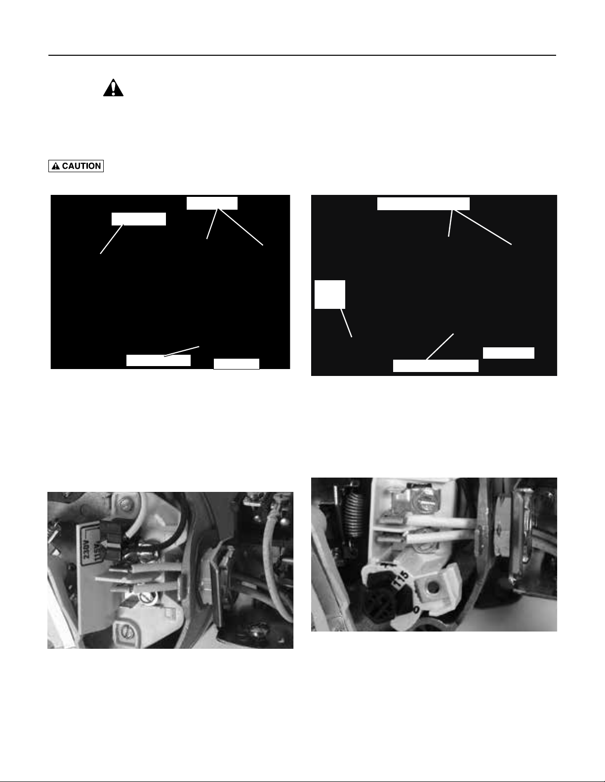
Disconnect power before working on pump, motor, pressure switch, or wiring.
MOTOR SWITCH SETTINGS
NOTE: 1/2 HP motors are wired for 115 volts only, and have no motor wiring to change.
3/4 HP or 1 HP motor terminal boards (located under the motor end cover) should look like one of those below.
If the motor can operate at either 115 or 230 volts, it is set at the factory to 230 volts. Do not change motor wiring
if line voltage is 230 volts, or if you have a single voltage motor.
Never wire a 115 volt motor to a 230 volt line.
Plug Type Voltage Selector
Power Connections
Voltage Change Plug
Dial Type Voltage Selector
Power Supply Connections
Voltage
Change
Dial
Ground Wire Connection
Pressure Switch
Figure 8: Voltage set to 230 volts, Plug Type
Voltage is factory set to 230 volts. To change to 115 volts:
1. Make sure power is off.
2. Pull the voltage change plug off of the tabs.
3. Move the voltage change plug to the 115 volt position. The plug will now cover 2 metal tabs and the
arrow on the plug will line up with the 115V arrow on
the label (see Figure 9).
Pressure Switch
Ground Wire Connection
Figure 10: Voltage set to 230 volts, Dial Type
Voltage is factory set to 230 volts. To change to 115 volts:
1. Make sure power is off.
2. Turn the dial counter-clockwise until 115 shows in
the dial window as shown in Figure 11.
3. Attach the incoming power leads to the two outer
screws on the pressure switch as shown in Figure 10.
Figure 9: Voltage set to 115 volts, Plug Type
4. Attach the incoming power leads to the two outer
screws on the pressure switch as shown in Figure 8.
5. Attach the ground wire to one of the grounding
connections, shown in Figure 8.
6. If there are other wires, they should be capped.
7. Reinstall the Motor end cover.
Figure 11: Voltage set to 115 volts, Dial Type
4. Attach the ground wire to the grounding connections
as shown in Figure 10.
5. If there are other wires, they should be capped.
6. Reinstall the Motor end cover.
Electrical 7
Hazardous voltage. Can shock, burn, or
kill. Connect ground wire before connecting power supply wires. Use the wire size (including the ground wire)
specified in the wiring chart. If possible, connect the
pump to a separate branch circuit with no other appliances on it.
Explosion hazard. Do not ground to a gas
supply line.
WIRING CONNECTIONS
Fire hazard. Incorrect voltage can cause a
fire or seriously damage the motor and voids the warranty. The supply voltage must be within ±10% of the motor
nameplate voltage.
NOTICE: Dual-voltage motors are factory wired for 230
volts. If necessary, reconnect the motor for 115 volts, as
shown. Do not alter the wiring in single voltage motors.
Install, ground, wire, and maintain your pump in compliance with the National Electrical Code (NEC) or the
Canadian Electrical Code (CEC), as applicable, and with
all local codes and ordinances that apply. Consult your
local building inspector for code information.
Connection Procedure:
Step 1. Connect the ground wire first as shown in Figure
11. The ground wire must be a solid copper wire
at least as large as the power supply wires.
Step 2. There must be a solid metal connection between
the pressure switch and the motor for motor
grounding protection. If the pressure switch is
not connected to the motor, connect the green
ground screw in the switch to the green ground
screw under the motor end cover. Use a solid
copper wire at least as large as the power supply
wires.
Step 3. Connect the ground wire to a grounded lead in
a service panel, to a metal underground water
pipe, to a metal well casing at least ten feet (3M)
long, or to a ground electrode provided by the
power company or the hydro authority.
Step 4. Connect the power supply wires to the pressure
switch as shown in Figure 11.
Table I: Wiring Chart – Recommended Wire and Fuse Sizes
Branch Distance in Feet (Meters);
Max Fuse Wire Size AWG (mm
Load Rating 0-100 101-200 201-300 301-400 401-500
Model HP Amps Amps (0-30) (31-61) (62-91) (92-122) (123-152)
115Volts:
5SL 1/2 9.9 15 14(2) 10(5.5) 8(8.4) 8(8.4) 6(14)
5HL 1/2 12.2 20 12(3) 10(5.5) 8(8.4) 6(14) 6(14)
7SL 3/4 12.2 20 12(3) 10(5.5) 8(8.4) 6(14) 6(14)
7HL 3/4 14.8 20 12(3) 8(8.4) 6(14) 6(14) 4(21)
10SL 1 14.8 20 12(3) 8(8.4) 6(14) 6(14) 4(21)
10HL 1 19.9 25 10(5.5) 8(8.4) 6(14) 4(21) 4(21)
15SL 1-1/2 19.9 25 10(5.5) 8(8.4) 6(14) 4(21) 4(21)
230 Volts:
5SL 1/2 5.0 15 14(2) 14(2) 14(2) 14(2) 12(3)
5HL 1/2 6.2 15 14(2) 14(2) 14(2) 12(3) 12(3)
7SL 3/4 6.2 15 14(2) 14(2) 14(2) 12(3) 12(3)
7HL 3/4 7.4 15 14(2) 14(2) 14(2) 12(3) 10(5.5)
10SL 1 7.4 15 14(2) 14(2) 14(2) 12(3) 10(5.5)
10HL 1 9.9 15 14(2) 14(2) 12(3) 10(5.5) 10(5.5)
15SL 1-1/2 9.9 15 14(2) 14(2) 12(3) 10(5.5) 10(5.5)
2
)
Replace all
Preparing to Start the Pump – Deep Well 8
Never run pump against closed discharge.
To do so can boil water inside pump, causing hazardous
pressure in unit, risk of explosion and possibly scalding
persons handling pump.
Never run pump dry. Running pump without
water may cause pump to overheat, damaging seal and
possibly causing burns to persons handling pump. Fill
pump with water before starting.
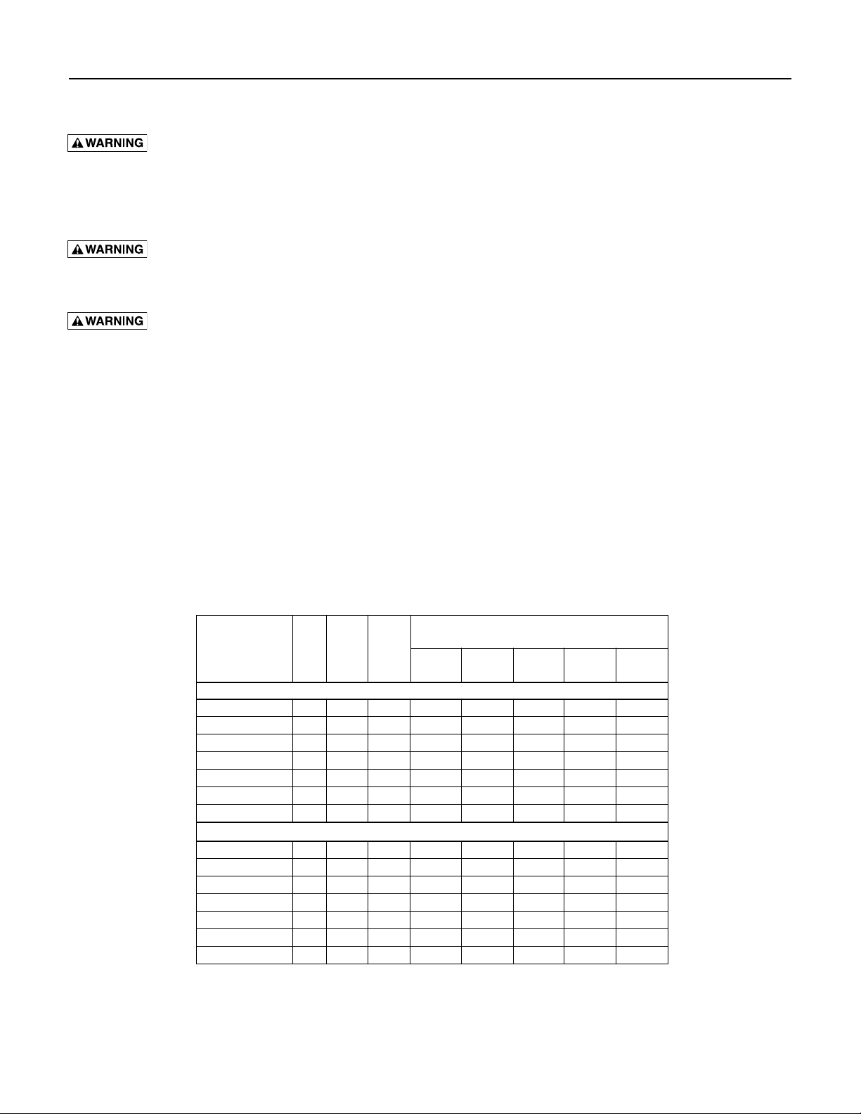
Step 1. Open the control valve as far as possible (see
Figure 12). Then remove the priming plug
from the pump and fill the pump, fill all piping
between the pump and the well, and make sure
that all piping in the well is full. If you have also
installed a priming tee in the suction piping,
remove the plug from the tee and fill the suction
piping.
Open control valve
as far as possible
and fill pump and
piping through
priming tee.
To Household
Pressure
Gauge
60
40
80
20
100
Water System
Step 3. Power on! Start the pump and watch the pressure
gauge. The pressure should build rapidly to 50
PSI as the pump primes.
Step 4. After 2 or 3 minutes, the gauge should show pres-
sure. If not, stop the pump, remove the fill plugs,
reopen the control valve, and refill the pump and
piping. You may have to repeat this two or three
times in order to get all the trapped air out of the
piping. Don’t forget to close the control valve each
time before you start the pump.
Step 5. When pressure has built up and stabilized at
about 50 PSI, slowly open the control valve (see
Figure 14) and let the pressure drop until the
pressure gauge needle starts to flutter. When the
needle flutters, close the valve just enough to
stop the flutter (see Figure 14). Your pump is now
operating at its most efficient point.
60
80
40
20
100
A-Open Control Valve
60
80
40
20
100
Figure 12: Fill Pump
Step 2. Replace all fill plugs and close the control valve
completely (Figure 13).
fill plugs and
close control
valve completely.
To Household
Water System
60
40
80
20
100
Figure 13: Prime Pump
B-Watch for Pressure Gauge to Flutter
60
80
40
20
100
C-Close Control Valve until Pressure
Stabilizes
Figure 14: Set Control Valve
Step 6. After the pump has built up pressure in the
system and shut off, check the pressure switch
operation by opening a faucet or two and running enough water out to bleed off pressure until
the pump starts. The pump should start when
pressure drops to 30 PSI and stop when pressure
reaches 50 PSI. Run the pump through one or
two complete cycles to verify correct operation.
This will also help clean the system of dirt and
scale dislodged during installation.
NOTICE: Packer jets (2" and 3" single pipe wells) do not
form a perfect seal. Normal irregularities in the cup seal
leather and the inner walls of the casing will allow the
pressure in a dormant system to leak off over time. This
will cause the pump to cycle periodically to maintain the
system pressure level.
Preparing to Start the Pump – Shallow Well 9
2411 0497
Never run pump against closed discharge.
To do so can boil water inside pump, causing hazardous
pressure in unit, risk of explosion and possibly scalding
persons handling pump.
Never run pump dry. Running pump without
water may cause pump to overheat, damaging seal and
possibly causing burns to persons handling pump. Fill
pump with water before starting.
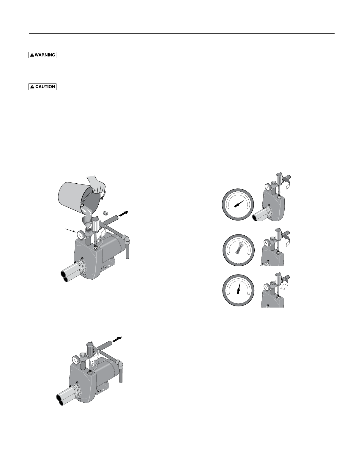
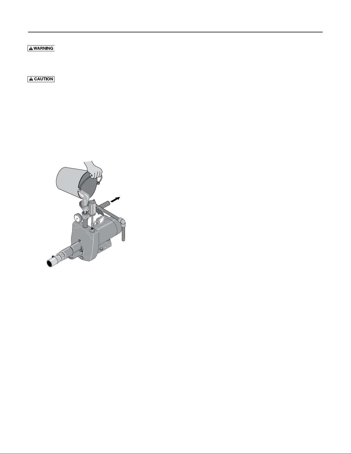
Step 1. Open the control valve as far as possible (see
Figure 15). Then remove the priming plug
from the pump and fill the pump, fill all piping
between the pump and the well, and make sure
that all piping in the well is full. If you have also
installed a priming tee in the suction piping,
remove the plug from the tee and fill the suction
piping.
Open control valve
as far as possible
and fill pump and
piping through
priming port
or priming tee.
To Household
60
80
40
20
100
Water System
Step 2. Replace all fill plugs. Leave the control valve
open (in a shallow well installation, the control
valve always stays open).
Step 3. Power on! Start the pump. The pump should
pump water in two or three minutes.
Step 4. If you don’t have water after 2 or 3 minutes, stop
the pump and remove the fill plugs. Refill the
pump and piping. You may have to repeat this
two or three times in order to get all the trapped
air out of the piping. The control valve remains
open throughout this procedure.
Step 5. After the pump has built up pressure in the
system and shut off, check the pressure switch
operation by opening a faucet or two and running enough water out to bleed off pressure until
the pump starts. The pump should start when
pressure drops to 30 PSI and stop when pressure
reaches 50 PSI. Run the pump through one or
two complete cycles to verify correct operation.
This will also help clean the system of dirt and
scale dislodged during installation.
Figure 15: Open Control Valve
 Loading...