


PCI 18/8-H
INSTALLATION
INSTRUCTIONS
18
B
C
A
3. INSTALLATION (authorized personnel)
3.1 Reference standard
Install in accordance with local building and electrical codes.
Failure to install a gas appliance correctly and in accordance with the above norms could lead to prosecution. It is
in the interest of the installer and safety that the codes are complied with.
The manufacturer’s instructions form an integral part of the installation and should be left with the appliance but do
not over ride in anyway statutory obligations.
Installation requirements
Please refer to local and national standards in force with the Country of destination of the product.
3.2 Unpacking
■ The materials (cardboard) used for packing the
appliance are fully recyclable.
■ It is recommended that the packing material is only
removed prior to installing the boiler. The manufacturer
will not be held responsible for damage caused by
incorrect storage of the product.
■ Packing materials (plastic bags, polystyrene, nails,
etc.) must not be left within reach of children, in that
these items represent a potential hazard.
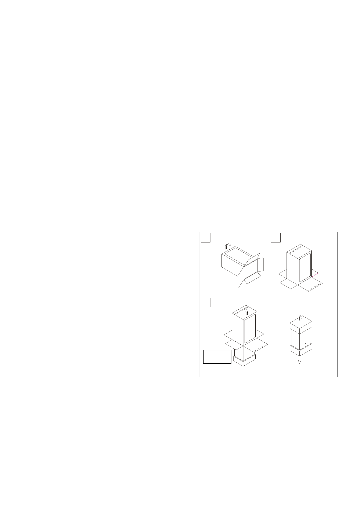
A. Place the packed appliance on the floor (see fig. 1)
making sure that the "up” arrow is facing down. Remove the
staples and open out the four flaps of the box.
B. Rotate the boiler 90° while manually supporting it from
underneath
C. Lift the box and remove the protections. Lift the boiler by
grasping the rear part and proceed with the installation.
STORAGE & HANDLING
Please note that prior to installation the Pensotti North
America boilers should be stored in the horizontal position
with no more than three boilers to a stack;
Ensure that the boilers are stored in dry conditions and be aware that the carton is a two-man lift;
Fig 1
INSTALLATION
INSTRUCTIONS
19
3.3 Installing the boiler.
The appliance must be installed
exclusively on a vertical solid wall capable of
supporting its weight.
■ The boiler should be fitted within the
building unless otherwise protected by a
suitable enclosure i.e. garage or outhouse.
(The boiler may be fitted inside a
cupboard)
■ /If the boiler is sited in an unheated
enclosure then it is recommended to leave
the ON/OFF switch always in ON position
to give frost protection.
■ If the boiler is installed in a room
containing a bath or shower reference
must be made to the relevant
requirements.
■ Appliance is approved for installation on
combustible walls.
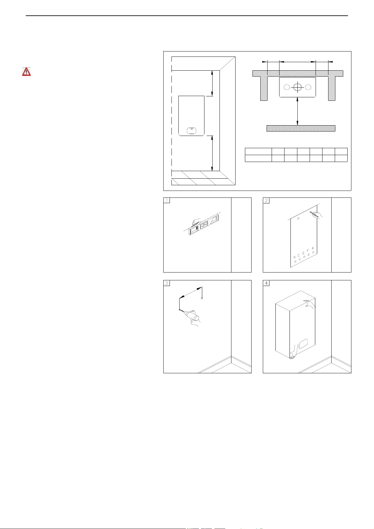
In order to allow access to the interior of the
boiler for maintenance purposes, it is
important that the minimum distances
indicated in figure 1 are respected. To make
the installation easier, the boiler is supplied
with a template to enable the pipe
connections to be positioned prior to fixing
the appliance to the wall.
To install the boiler, proceed as follows (see
fig. 2):
a. Use a level (of not less than 24” long) to
mark a horizontal line on the wall where
the boiler is to be fitted.
b. Position the top of the template along the
line drawn with the level, respecting the
distances indicated. Then mark the
centres of the positions of the two wall
screws or anchors. Finally, mark the
positions of the water and gas pipes.
c. Remove the template and install the
domestic hot and cold water pipes, the
gas supply pipe and the central heating
pipes using the fittings supplied with the
boiler.
Fix the boiler to the wall using the bracket
and connect the pipes.
MINIMUM DISTANCES [INCHES]
H
A
X
L
Y
Model
PCI 18/8
X Y L H
40
17.7
2.52.5
B
A B
14 12
Fig. 1
Fig. 2
INSTALLATION
INSTRUCTIONS
19
3.4 Water connections
In order to safeguard the heat exchanger and circulation pump, especially in case of boiler replacement, it
is recommended that the system is hot-flushed
to remove any impurities (especially oil and
grease) from the pipes and radiators.
In order to safeguard all waterside
components the supplied Fernox
Commissioning Kit Must be used in its
entirety.
Make sure that the domestic water and central
heating pipes are not used to earth the
electrical system. The pipes are totally
unsuitable for this purpose.
Isolation Valves must be installed on the
heating and D.H.W circuits. This will facilitate
all maintenance and service operations where
the boiler needs to be drained.
To prevent vibration and noise coming from the
system, do not use pipes of reduced diameter,
short radius elbows or severe reductions in the
cross sections of the water passages.
In order to guarantee the reliability of the water a
pressure reducing valve and backflow preventer
must be installed
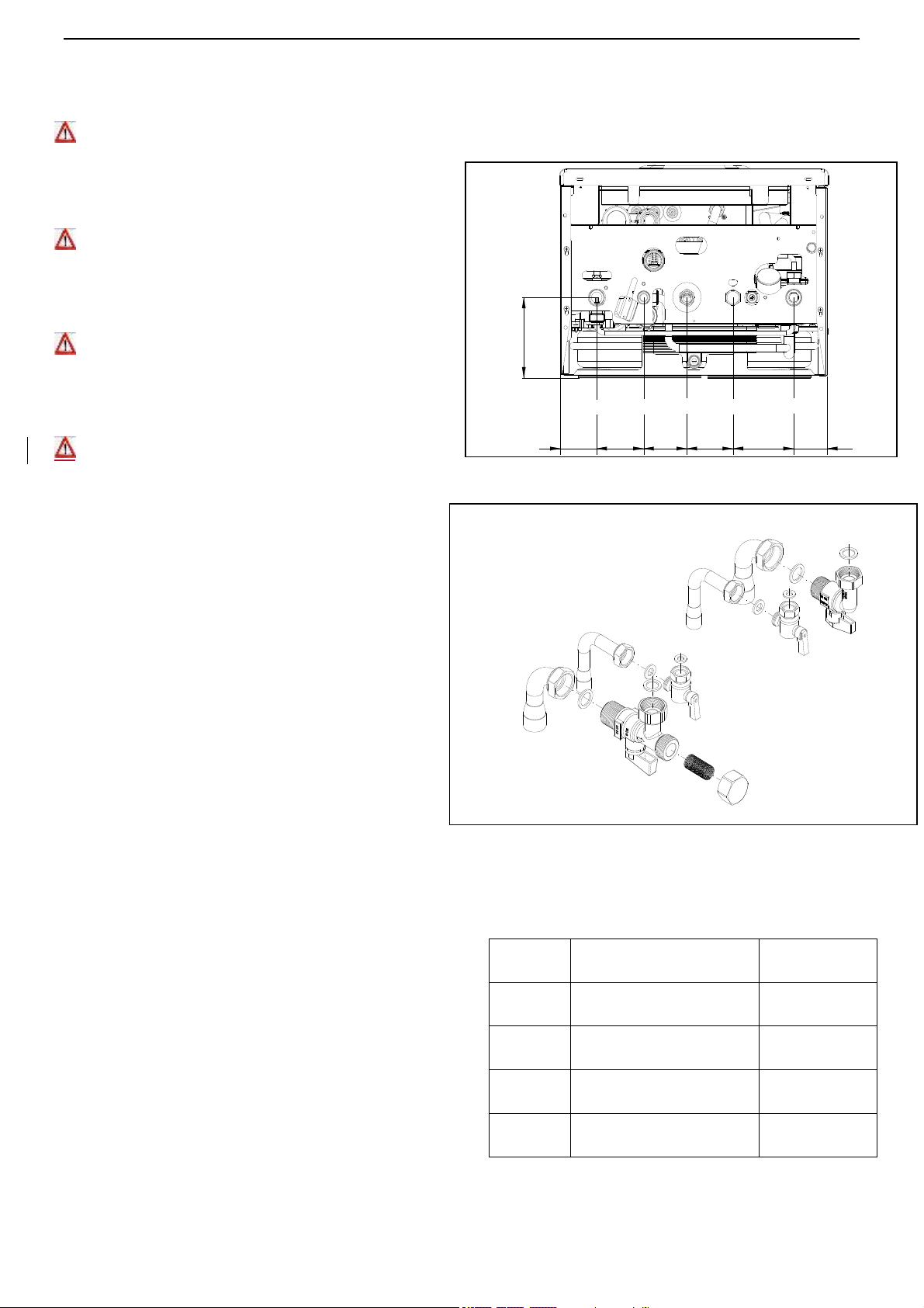
To facilitate the installation, the boiler is supplied
with an hydraulic connection kit (see fig.2).
A pressure relief valve is installed in this dual purpose
boiler that is rated in accordance with and complying
with either The Standard for relief Valves and
Automatic Shutoff Devices for Hot Water Supply
Systems, AINSI Z21.22 or The ANSI/ASME Boiler and
Pressure Vessel Code, Section IV (Heating Boilers).
The relief valve must be installed such that the
discharge will be conducted to a suitable place for
disposal when relief occurs. The discharge line must
be installed to allow complete drainage of both the
valve and the line. If this unit is installed with a
separate storage vessel, the separate vessel must
have its own temperature and pressure relief valve.
This valve must also comply with The Standard for
Relief Valves and Automatic Shutoff Devices for Hot
Water Supply Systems. AINSI Z21.22 (in the U.S.
only). A temperature relief valve is not required but if
one is used, do not install the valve with the probe
directly in the flow of water. This may cause
unwarranted discharge of the valve.
LEGEND
HR
HEATING RETURN
Ø 3/4"
HF
HEATING SUPPLY
Ø 3/4"
G
GAS
Ø 1/2"
CWI
COLD WATER INLET
Ø 1/2"
HWO
HOT WATER OUTLET
Ø 1/2"
5.1
HF
CWI
G
HR
HWO
2.5 3.1
2.7
3.2
4
2.2
HR
HWO
CWI
HF
Fig. 2
Fig. 1
INSTALLATION
INSTRUCTIONS
20
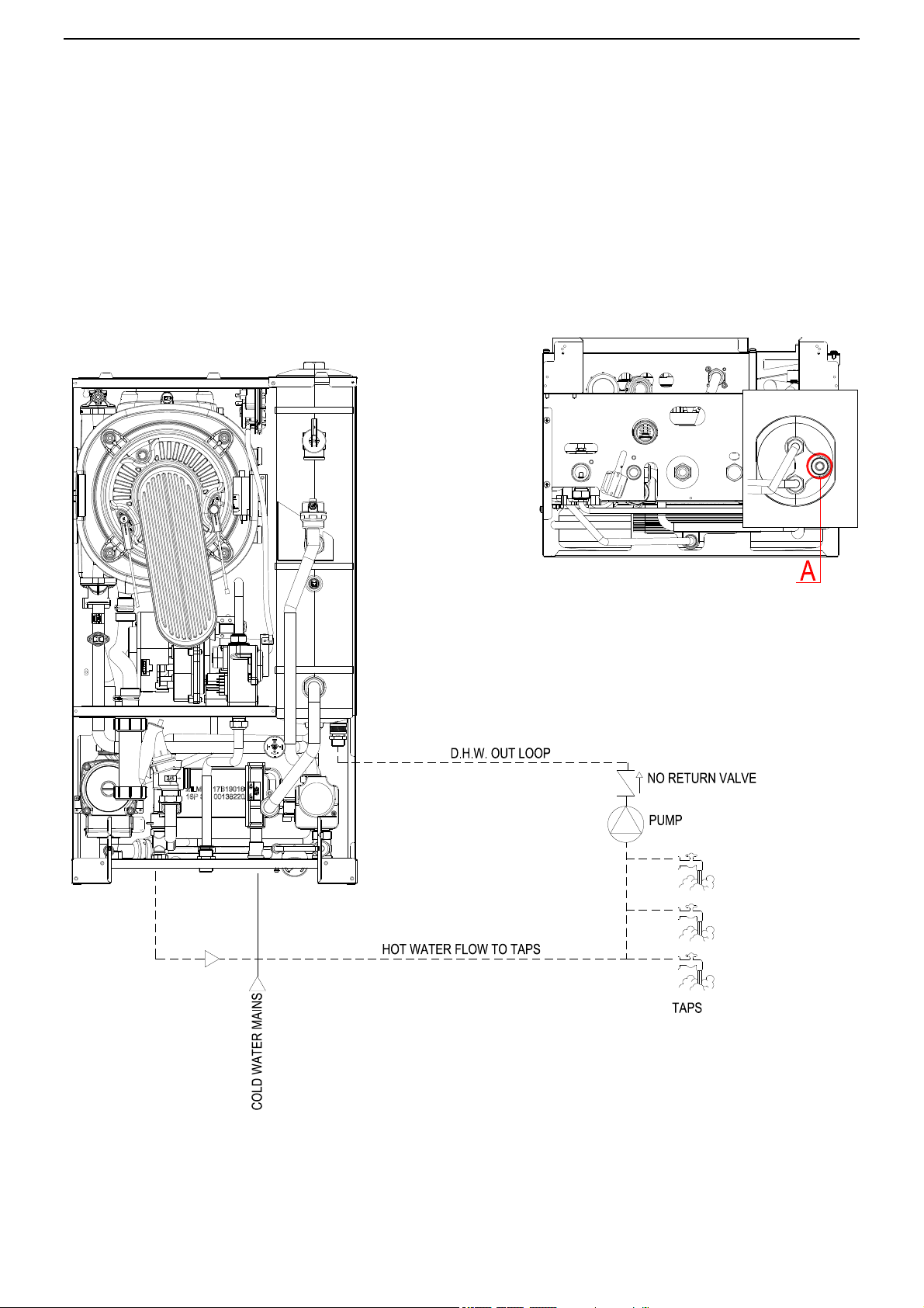
D.H.W. circulating loop
In order to joint the D.H.W out loop pipe, proceed as follows:
a) unscrew the ½” cap A and insert a ½” nipple;
b) joint the nipple to the D.H.W. circulating pipe;
INSTALLATION
INSTRUCTIONS
21
3.5 Domestic Hot Water Circuit
■ In order to prevent scaling and eventual damage to the D.H.W heat exchanger, the mains water supply must not
have a hardness rating of more than 7 grains/gal (120 ppm). It is nevertheless advisable to check the properties of
the water supply and install the appropriate treatment devices where necessary.
The cold water supply pressure at the inlet to the boiler must be between 7.25 psi (0.5 bar) and 87 psi (6 bar).
In areas with higher water inlet pressure a pressure reducing valve must be fitted before the boiler.
The frequency of the heat exchanger coil cleaning depends on the hardness of the mains water supply and the
presence of residual solids or impurities, which are often present in the case of a new installation. If the
characteristics of the mains water supply are such that require it to be treated, then the appropriate treatment
devices must be installed, while in the case of residues, an in-line filter should be sufficient.
Central heating circuit
In order to prevent scaling or deposits in the primary heat exchanger, the mains supply water to the heating circuit
must be treated according to the requirements of local standards.
This treatment is indispensable in the case where the circuit is frequently topped-up or when the system is often
either partially or fully drained.
In order to safeguard all waterside components, the supplied Fernox Commissioning Kit Must be used in
its entirety.
Condensate drain
Refer to the city, town or municipality have jurisdiction for codes regarding the proper discharge of
condensate.
The condensate drain flexible pipe supplied with the boiler must be connected to a proper condensate trap. The
condensate discharge into the drainage system is allowed providing a condensate trap (siphon) is installed.
Any condensate discharge pipe work external to the building (or in an unheated part of it) must be insulated to
protect against frost. Before switching the boiler On, check the correct condensate discharge.
Expansion Tank Capacity
Max. System Operating
Temperature (°F)
Maximum System Water
Content (Gals.)*
100
114
110
85
120
65
130
52
140
43
150
36
160
30
170
26
180
24
Pensotti requires the
installation of a pressure
reducing valve & backflow
preventer with all Solenne
Series boilers.

INSTALLATION
INSTRUCTIONS
22
3.6 Piping Diagram
Dirt / Scale Separation
Along with the application of our Fernox commissioning kit Pensotti highly recommends the installation
of a dirt separator in the return piping of all Solenne Series boiler models. Follow the manufacturer’s
instructions when installing these devices.
This piping diagram is an example for illustrative purposes only.
It is not designed to be used as a piping schematic.
*Max. 4 pipe diameters between tees
*External Low Water Cut-Off if required by local code
*Tempering Valve May be Required – Consult Local Codes
*Must leave at least 15” of straight pipe on either side of
closely spaced tees
INSTALLATION
INSTRUCTIONS
23
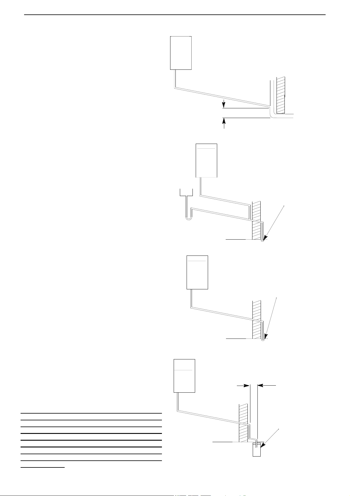
3.7 Condensate drain
FAILURE TO INSTALL THE CONDENSATE
DISCHARGE PIPEWORK CORRECTLY WILL
AFFECT THE RELIABLE OPERATION OF THE
DUAL PURPOSE BOILER. The condensate
discharge pipe MUST NOT RISE at any point along
its length. There MUST be a fall of AT LEAST 2.5° (1”
per 20”) along the entire run.
I. The condensate outlet terminates in 7/8” nut and
seal for the connection of 7/8” plastic overflow pipe
which should generally discharge internally into the
household drainage system. If this is not possible,
discharge into an outside drain is acceptable.
2. Ensure condensate piping, neutralizer, and
discharge of condensate complies with any and all
local and national codes.
3. The discharge pipe should be run in a proprietary
drain pipe material e.g. PVC, PVC-U, ABS, PVC-C or
PP.
4. Metal pipe work is NOT suitable for use in
condensate discharge systems.
5. The pipe should be a minimum of 7/8” diameter and
must be supported using suitably spaced clips to
prevent sagging.
6. Any pipe fitted externally must not exceed 10 feet.
7 Any condensate discharge pipe work external to the
building (or in an unheated part of it e.g. garage) must
be insulated to protect against frost. It is also
recommended that the pipe diameter is increased to 1
¼”.
8. If the boiler is fitted in an unheated location the
entire condensate discharge pipe should be treated
as an external run.
9. In alI cases discharge pipe must be installed to aid
disposal of the condensate. To reduce the risk of
condensate being trapped, as few bends and fittings
as possible should be used.
10. When discharging condensate into a soil stack or
waste pipe the effects of existing plumbing must be
considered. If soil pipes or waste pipes are subjected
to internal pressure fluctuations when WC's are
flushed or sinks emptied then back-pressure may
force water out of the boiler trap and cause appliance
lockout.
Information Only:
Examples are shown of the following methods of
termination:-
i) to an internal soil & vent pipe
ii) via an internal discharge branch (e.g. sink waste)
iii) to a drain or gully
iv) to a purpose made soak away
Ensure condensate piping, neutralizer, and
discharge of condensate complies with any and
all local and national codes.
IF, FOR ANY REASON, THE CONDENSATE
DRAINAGE SYSTEM FAILS AND CONDENSATE IS
PERMITTED TO FLOW BACK INTO THE
INTERNAL CONDENSATE BOTTLE INSIDE THE
BOILER, THE BOILER WILL STOP AND WILL
DISPLAY AN E01 ERROR. THE CONDENSATE
DRAINAGE SYSTEM PROBLEM MUST THEN BE
CORRECTED BEFORE THE BOILER IS PUT BACK
IN OPERATION.
18" min
Holes in the soak-away must
face away from the building
20" min
External termination to a purpose made soak-away
External termination to a drain or gully
Pipe must terminate above
water level but below
surrounding surface
1" per 20" of pipe run
2.5° Minimum fall
1" per 20" of pipe run
2.5° Minimum fall
Boiler
Pipe must terminate above
water level but below
surrounding surface
1" per 20" of pipe run
2.5° Minimum fall
External termination via internal discharge
branch e.g. sink waste - downstream
Sink
2.5° Minimum fall
1" per 20" of pipe run
Termination to an internal soil and vent pipe
Boiler
Boiler
Boiler

INSTALLATION
INSTRUCTIONS
24
3.8 Gas Connection
3.8.1 Gas Piping Guidelines
Follow all local codes and/or the most recent edition of the National Fuel Gas Code (ANSI Z223.1/NFPA 54) in
the USA or the Natural Gas and Propane Installation Code in Canada (CAN/CSA B149.1).
3.8.2 Gas Supply Lines Pressures
The minimum and maximum inlet gas pressures are Natural Gas Min. 7.00”WC – Max. 14.00”WC. and
Propane Gas Min. 11.00”WC – Max. 21.00”WC.
Gas pressures over and above the specified range will result in adverse performance and
dangerous operating conditions; any damage resulting from extreme gas supply pressures will not
be covered by the limited warranty.
Until pressure testing of the main gas supply line is completed, ensure the gas line to the
PENSOTTI Boiler is disconnected to avoid any damage to the boiler.
The appliance and its individual shut off valve must be disconnected from the gas supply piping
system during any pressure testing of that system at test pressures in excess of 0.5 psi (3.5 kPa)..
The appliance must be isolated from the gas supply piping system by closing its individual manual
shut-off valve during any pressure testing of the gas supply system at test pressures equal to or less
that 0.5 psi (3.5 kPa).
The gas appliance and its gas connections must be leak tested before placing the appliance in
operation. Leaks can be found by using a gas leak detection device or by applying soapy water
to all gas fittings. Should bubbles occur, tighten those connections and re-test.
Always purge the gas line for any debris before connecting to the boiler gas inlet.
Never use an open flame to test for gas leaks as property damage, personal injury or death could result.
The maximum inlet gas pressure must not exceed the valve specified by the manufacturer and that the
minimum valve listed as for the purposes of input adjustment.
The connection to the gas supply must be carried out by professionally qualified personnel in accordance with
the relevant standards.
■ Check the internal and external seals of the gas supply system.
■ A gas shut-off valve and sedim ent trap must be installed upstream of the appliance .
■ Before starting up the boiler, make sure that the type of gas corresponds to that for which the appliance has
been set-up.
■ The gas supply pressure must be between the values reported on
the rating plate.
■ Conversion of the appliance from natural gas to LPG or vice
versa must be carried out by qualified personnel.
■ The power supply cable must be replaced by a qualified
electrician. If the cable is damaged in any way, switch off the
appliance and have the cable replaced by a suitably qualified
electrician.
When using an electrical appliance, a few fundamental rules
must be observed: Do not touch the appliance with damp or
wet parts of the body or when barefoot. Do not pull on the
electric wires.
Do not allow the appliance to be used by children or anyone
unfamiliar with its operation.
INSTALLATION
INSTRUCTIONS
25
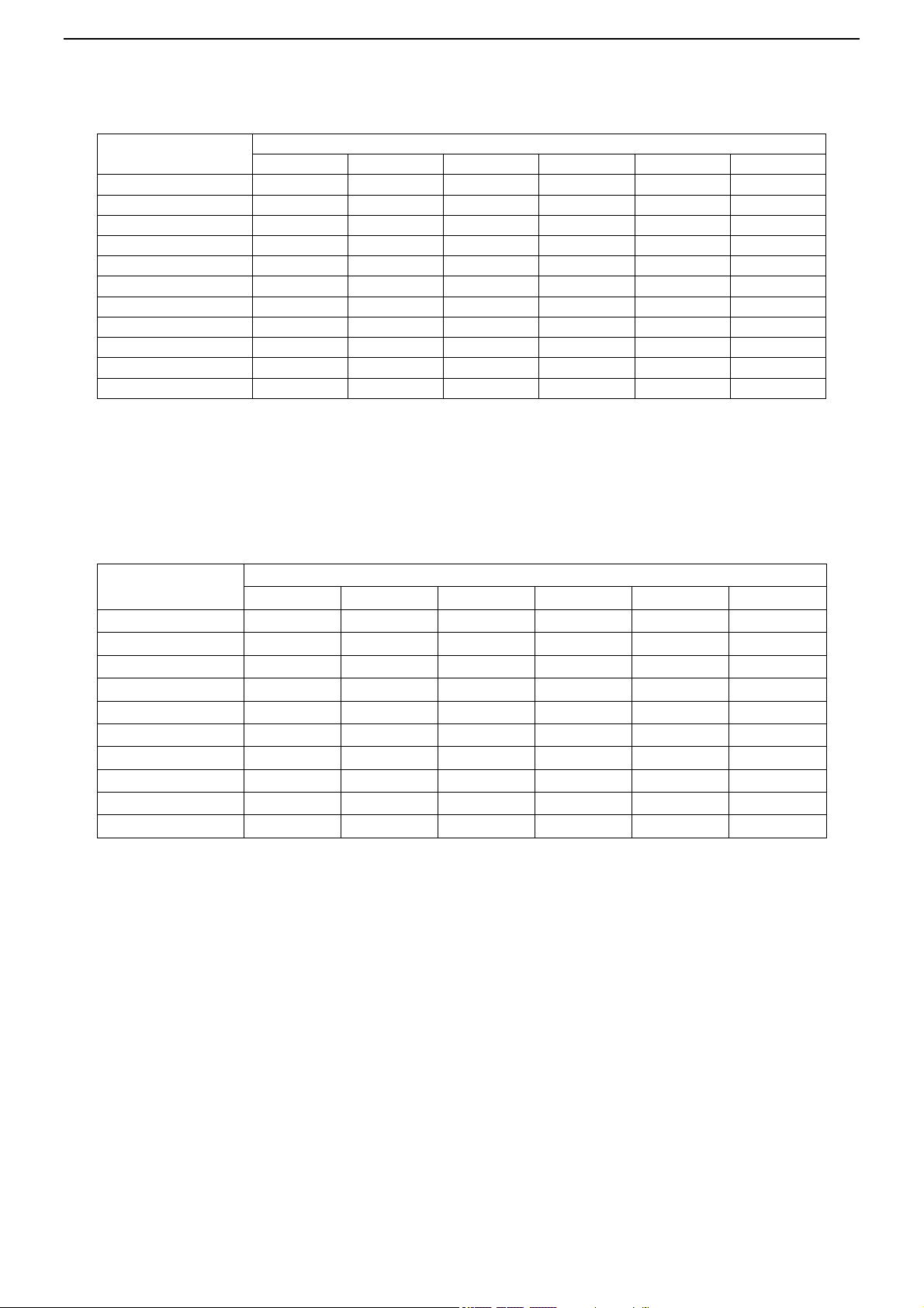
Natural Gas Pipe Sizing Chart
Length of
Pipe In Feet
Size of Schd. 40 Black Iron Pipe in Inches
1/2"
3/4"
1"
1-1/4"
1-1/2"
2"
10
108
230
387
793
1237
2259
20
75
160
280
569
877
1610
30
61
129
224
471
719
1335
40
52
110
196
401
635
1143
50
46
98
177
364
560
1041
60
42
89
159
336
513
957
70
38
82
149
317
476
896
80
36
76
140
239
443
840
90
33
71
133
275
420
793
100
32
68
126
266
411
775
125
28
60
117
243
369
700
Natural Gas flow is given in thousands of BTU/hr. - One cubic foot of natural gas = 1000 BTU
Nominal pressure at the burner for Natural Gas is 3.5" of water column. (Typical machine supply 5"-7")
Pipe length must include additional length for all fittings. Add approximately 5 feet of pipe per fitting
Natural Gas Example: A machine with a burner that requires 440,000 BTU would need a 1 -1/4" pipe for
a 20' long run.
Liquid Propane Gas Pipe Sizing Chart
Length of
Pipe in Feet
Size of Schd. 40 Black Iron Pipe in Inches
1/2"
3/4"
1"
1-1/4"
1-1/2"
2"
10
275
567
1071
2205
3307
6221
20
189
393
732
1496
2299
4331
30
152
315
590
1212
1858
3465
40
129
267
504
1039
1559
2992
50
114
237
448
913
1417
2646
60
103
217
409
834
1275
2394
80
89
185
346
724
1086
2047
100
78
162
307
630
976
1811
125
69
146
275
567
866
1606
150
63
132
252
511
787
1496
LP Gas flow is given in thousands of BTU/hr. - One cubic foot of LP gas - 2516 BTU
This chart refers to low pressure LP, after regulation Standard nominal pressure at the burner for
Liquid Propane Gas is 11" of water column.
Pipe length must include additional length for all fittings. Add approximately 5 feet of pipe per fitting
LP Example: A machine with a burner that requires 440,000 BTU would need a 1" pipe for a 20' long run.
Make sure the boiler is operating normally.
Shut down the unit by pressing the ON/OFF button on the control panel.
Remove the front panel and disconnect the flame rod sensor.
Restart the boiler. The burner should light but shut down after a few seconds.
If that is the case, the system is OK. It the burner does not shut down, push the ON/OFF switch to
shut down the boiler and perform a troubleshooting procedure.

INSTALLATION
INSTRUCTIONS
25
3.9 Electrical connections
3.9.1 General warnings
Follow the electrical code requirements of the local authority having jurisdiction. In the absence of
such requirements, follow the latest edition of the National Electrical Code (NFPA 70) in the U.S.
or the latest edition of CGA C22.1 Canadian Electrical Code – Part 1 in Canada.
3.9.2 Electric Wiring: Ground and Surges
All units come with factory installed 3-pronged (grounded) plug end. The boiler can be plugged into
any standard electrical duplex outlet close to the unit as it requires only 4 Amps.
If the local jurisdiction requires the unit to be wired directly, remove and discard the factory installed plug. An
ON/OFF switch controlling the main power between the breaker and the Boiler should be provided to facilitate
end-user maintenance and servicing. This should be done by a qualified electrician.
The boiler must be electrically grounded. Ensure the electrical receptacle, in which the boiler will be
plugged into, is properly grounded; if wiring directly, do not attach the ground wire to either the gas or the
water piping as plastic pipe or dielectric unions may isolate the boiler electrically.
The use of a surge protector, surge capacitor, line conditioner or equivalent is recommended to protect the
appliance from power surges.
If a generator is to be used as “backup” power care must be taken that a line conditioner is used to protect the
appliance from erratic voltage.
If the boiler is to be installed in a structure utilizing a emergency stand-by generator, the installation of a surge
capacitor, surge protector, line conditioner or equivalent is required.
If the boiler is to be installed in a structure where frequent power outages are experienced the installation of a
surge capacitor, surge protector, line conditioner or equivalent is required.
Do not energize electric power to the unit until all plumbing and gas piping is complete and the boiler has
been filled with water.
The electrical supply required by the boiler is 120VAC at 60Hz with a maximum 4A rating with proper
grounding. Protection must be in place to prevent the Boiler from being exposed to voltage in excess of
130VAC Max or 95VAC Min.
Damage caused by excessive voltage is not covered under warranty.
DO NOT connect 220-240VAC and any other voltage to this PENSOTTI Boiler. This will damage the boiler
and void the warranty.
Do not disconnect the power supply when the unit is in normal operation.
If there is a power failure in cold weather areas, the freeze prevention system in the boiler will not operate
and may result in freezing of the heat exchanger; in cold weather areas where power failures are
common, you must completely drain the unit to prevent damage if the power will be off for any extended
period of time.
Damage caused by freezing is not covered under warranty.
CAUTION : Label all wires prior to disconnection when servicing controls. Wiring errors can cause improper
and dangerous operation. Verify proper operation after servicing.
The connection to the main power supply must be carried out by professionally qualified electrical personnel,
registered in accordance with current legislation and local authorities.

INSTALLATION
INSTRUCTIONS
26
Always check to make sure that the appliance has an efficient ground system. This requirement is only
satisfied if it has been properly connected to an efficient ground system installed in accordance with the
requirements of current safety standards and carried out by professionally qualified personnel.
This basic safety measure must be checked, verified and carried out by professionally qualified personnel.
Have the electrical system checked by a qualified electrician. The manufacturer will not be held liable for any
damage or injury caused as a result of an inefficient or faulty ground system.
■ Ensure the domestic power supply is checked by a qualified electrician to ensure that it can support the
maximum power absorption of the appliance, as indicated on the rating plate. In particular, make sure that the
cable sizes are adequate for the power absorbed by the appliance;
■ The power supply cable must be replaced by a qualified electrician. If the cable is damaged in any way, switch
off the appliance and have the cable replaced by a suitably qualified electrician;
When using an electrical appliance, a few fundamental rules must be observed:
Do not touch the appliance with damp or wet parts of the body or when barefoot.
Do not pull on the electric wires.
Do not allow the appliance to be used by children or anyone unfamiliar with its operation;
If the unit fails to re-start after any fault, unplug the unit for 30 seconds, then re-plug in the unit
and try to restart with the on/off switch. If the unit fails to restart, call a qualified Technician
for service.
INSTALLATION
INSTRUCTIONS
27
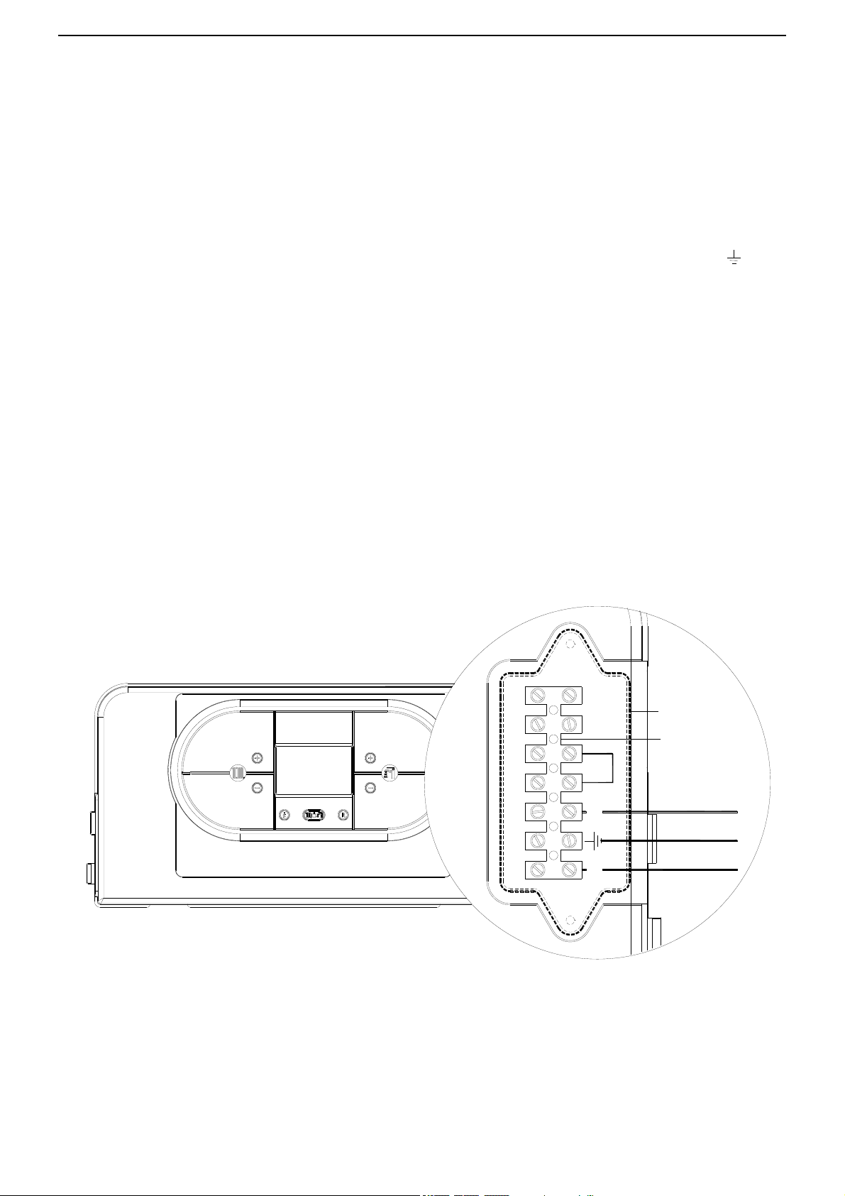
A
B
SeSeTaNL Ta
yellow/green
blue
brown
Electrical Connections
Connect the power supply to the terminal board inside the control panel as follows:
a. Switch off the power supply at service switch or breaker.
b. Remove the front case panel of the boiler.
c. Slacken the screws and remove plate A (see fig. 1).
d. With the plate removed, connect the wires to the terminal board B as follows:
Connect the earth wire (normally coloured green/yellow) to the terminal marked with the earth symbol “ “.
Connect the neutral wire (normally coloured blue) to the terminal marked with the letter “N”.
Connect the live wire (normally coloured brown) to the terminal marked with the letter “L”.
Terminals identified by the letters: Ta Room thermostat or End Switch
Se Outside temperature sensor
Ta terminals are 24V DC. Only a non-power robbing, battery operated thermostat or dry set of contacts can be installed
on Ta terminals.
When the wires have been connected, place plate “A" back to position. Switch the power supply back on.
 Loading...