

Page 1
1401 North Plano Road, Richardson, Texas 75081
Phone: 972-234-3202 Fax: 972-497-0468
Unpacking
Place carton in an upright position and
remove staples or use a sharp (knife
edge) tool to CAREFULLY cut or scribe
the sealing tape on both sides at the top
of the carton. Open carton flaps. Remove
any cardboard and wooden filler pieces,
as well as loose components or accessories shipped with the unit.
Carefully remove the unit from the carton.
Inspect the unit for any damage that may
have occurred during transit and check
for loose, missing or damaged parts.
Installation
WARNING
To reduce the risk of fire, electrical
shock, or injury to persons, observe
the following:
1. Use this unit only in the matter
intended by the manufacturer. If you
have questions, contact the manufacturer at the address or telephone
number listed in the warranty.
2. Before servicing or cleaning unit,
switch power off at service panel
and lock service panel to prevent
power from being switched
on accidentally.
3. Installation work and electrical
wiring must be done by a qualified
person(s) in accordance with all
applicable codes and standards,
including fire-rated construction
codes and standards.
4. Sufficient air is needed for proper
combustion and exhausting of gases
through the flue (chimney) of fuel
burning equipment to prevent backdrafting. Follow the heating equipment manufacturer’s guideline and
safety standards such as those published by the National Fire
Protection Association (NFPA), and
the American Society for Heating,
Refrigeration and Air Conditioning
Engineers (ASHRAE), and the
local code authorities.
5. When cutting or drilling into wall
or ceiling, do not damage electrical
wiring and other hidden utilities.
6. Ducted fans must always
be vented to the outdoors.
7. If this unit is to be installed over a
tub or shower, it must be marked as
appropriate for the application.
8. Never place a switch where it can
be reached from a tub or shower.
9. This unit must be grounded.
CAUTION
1. For general ventilating use only. Do
not use to exhaust hazardous or
explosive materials and vapors.
2. This product is designed for ceiling
installation only. DO NOT MOUNT
THIS PRODUCT IN A WALL.
3. To avoid motor bearing damage and
noisy and/or unbalanced impellers,
keep drywall spray, construction
dust. etc. off power unit.
4. Please read specification label on
product for further information and
requirements.Installation
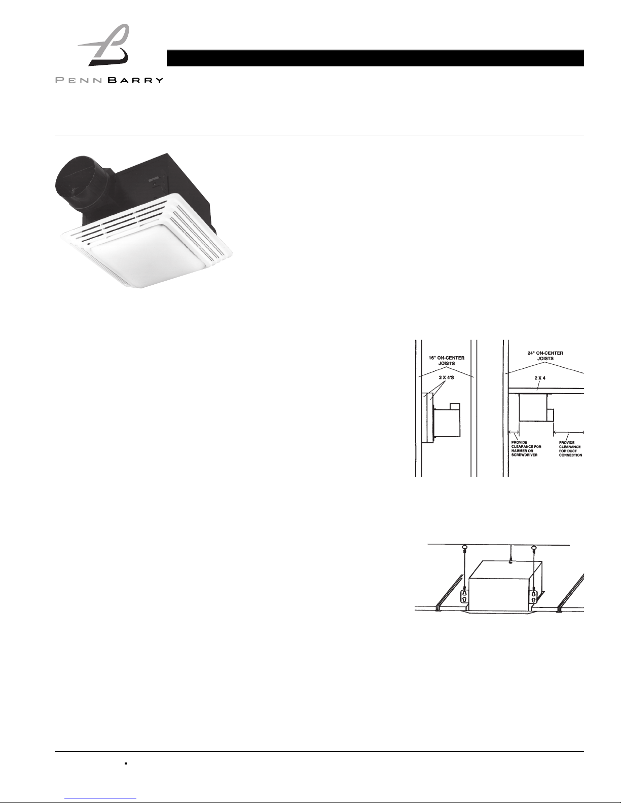
MOUNTING OPTIONS
Figure 1
1. Housing can be installed anywhere
between joists using 2" X 4" support(s) as shown.
Figure 2
2. Housing can be installed in a suspended ceiling using wire as shown.
Operation & Maintenance Manual
Printed in the USA Jan 2005
PART #99042905
Receiving and Handling
PennBarry fans are carefully inspected before leaving the factory. When the unit is
received, inspect the carton for any signs of tampering. Inspect the unit for any damage that may have occurred during transit and check for loose, missing or damaged
parts. Mishandled units can void the warranty provisions. PennBarry is not responsible for damages incurred during shipment. Avoid severe jarring and/or dropping.
Handle units with care to prevent damage to components or special finishes.
Storage
Long-term storage requires special attention. Units should be stored on a level,
solid surface, preferably indoors. If outside storage is necessary, protect the
units against moisture and dirt by encasing the cartons in plastic or some similar
weatherproof material.
Zephyr Heavy Duty Combination Fan/Light
Ventilating Fan Models ZL1 & ZL2
Read carefully before attempting to assemble, install, operate or maintain the product described. Protect yourself and others by observing all safety information.
Failure to comply with instructions could result in personal injury and/or property damage! Retain instructions for future reference.
PLEASE READ AND SAVE THESE INSTRUCTIONS.
Page 2
Operation & Maintenance Manual
Zephyr Ceiling/Wall Ventilating Fans Models ZL1 & ZL2
2 PENNBARRY
1401 North Plano Road, Richardson, Texas 75081
Phone: 972-234-3202 Fax: 972-497-0468
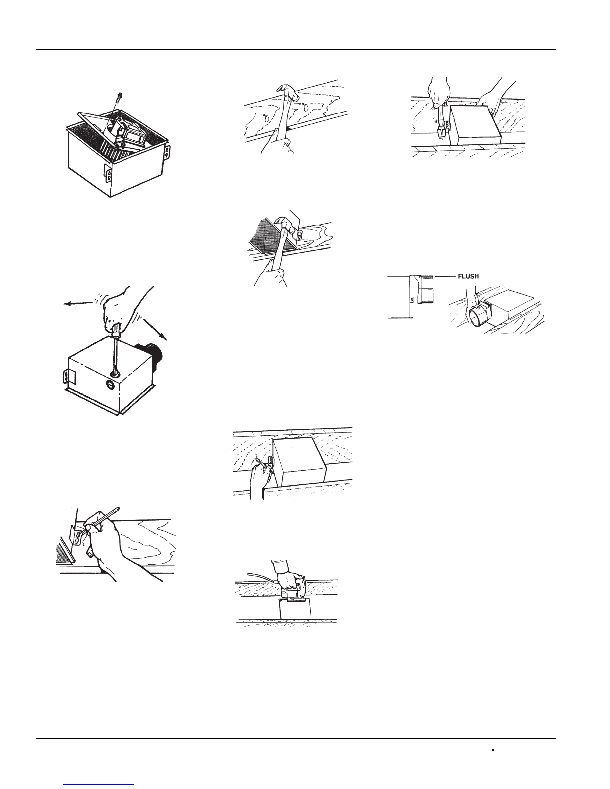
PREPARE THE FAN/LIGHT
Figure 3
1. Unplug motor and remove the sheet
metal screw next to the receptacle.
Lift the fan assembly out of the
housing, being careful not to bend
blower wheel.
Figure 4
2. Choose either the top or side knockout. Remove knockout by bending it
back and forth to break tabs.
INSTALLATION OF THE FAN LIGHT
New Construction
Figure 5
1. Choose the location for your fan/
light in the ceiling. For best possible
performance, use the shortest
possible duct run and a minimum
number of elbows.
2. Position mounting brackets against
joist so that bottom edge of housing
will be flush with finished ceiling. A
handy measuring guide is embossed
on the housing to make this easy.
Mark the top keyhole slot on both
mounting brackets.
Figure 6
3. Set housing aside and drive nails
partially into joist at the top of both
keyhole marks.
Figure 7
4. Hang housing from nails and
pound nails tight. To ensure a
noise-free mount, pound another
nail through the lower hole of
each mounting bracket.
Existing Construction
1. Choose the location for your fan/
light in the ceiling. For best possible
performance, use the shortest
possible duct run and a minimum
number of elbows.
Figure 8
2. In attic, position mounting brackets
against joist. Trace outline of housing on ceiling material.
Figure 9
3. Set housing aside and cut ceiling
opening slightly larger than marked.
Figure 10
4. Place housing in opening so that its
bottom edge is flush with finished
ceiling. Nail to joist through top keyhole on both sides. To ensure a
noise-free installation, drive another
nail through the lower hole of each
mounting bracket.
DUCT WORK
Figure 11
1. Snap the damper/duct connector
onto housing. Make sure that
tabs on the connector lock into
slots in housing. Top of damper/
duct connector should be flush
with top of housing.
2. Connect 4" round duct to
damper/duct connector and extend
duct to outside through a roof or wall
cap. Check damper to make sure
that it opens freely. Tape all duct
connections to make them secure
and air tight.
Page 3

WIRING
Figure 12
1. Wire unit following diagram above.
Run electrical cable as direct as
possible to unit. Do not allow cable
to touch sides or top of unit after
installation is complete.
Do not allow wires
to hang over edge
of scroll band.
Push all wiring up into corner of unit.
Wire left hanging over this edge will
become pinched or severed when
fan assembly is installed. Electrical
shock may result.
2. Replace fan assembly and secure
with sheet metal screw. Plug motor
into BLACK receptacle.
ATTACHING THE GRILL
Figure 13
1. Slide light reflector into front of grill
opening. Plug light into WHITE
receptacle. Place grill/reflector combination over protruding screw, and
fasten into place using acorn nut
provided. HAND-TIGHTEN acorn
nut 1/4 turn after it is snug.
Figure 14
2. Install light bulb (100 Watt Max.).
Insert one tab on light lens into a
slot in the grill/reflector combination.
Squeeze other tab slightly and snap
into remaining slot.
Use And Care
Disconnect electrical
power supply and lock
out service panel before cleaning or servicing this unit.
BULB REPLACEMENT
Remove lens by gently depressing sides
and pull down. Use 100 Watt maximum
incandescent bulb.
MOTOR LUBRICATION
The motor is permanently lubricated. Do
not oil or disassemble motor.
CLEANING
TO CLEAN LENS AND GRILL
Remove light lens and bulb. Remove nut
in center of reflector and lower assembly.
and reflector are
separate units. Unplug
light from white receptacle. Plastic
parts can be cleaned with mild, soapy
water (use a mild detergent, such as
dishwashing liquid) and dried with a soft
cloth. Do not use abrasive cloth, steel
wool pads, or scouring powders.
TO CLEAN FAN ASSEMBLY
Unplug fan assembly (BLACK receptacle). Remove screw near receptacle and
lift fan assembly out. Gently vacuum fan,
motor and interior of housing. METAL
AND ELECTRICAL PARTS SHOULD
NEVER BE IMMERSED IN WATER.
Parts Replacement
If replacing parts, do so with properly
selected components which duplicate the
original parts correctly. Incorrectly sized
parts can damage the fan.
PARTS LIST
Refer to figure 15.
1. Plastic Lens
2. Acorn Nut
3. Bulb Holder
4. Light Reflector (Includes Keys 3 & 4)
5. Grill
6. Motor Plate
7. Fan Motor
8. Blower Wheel
9. Receptacle (Black)
10. Receptacle (White)
11. Housing
12. Damper/Duct Connector
13. Grounding Clip
14. #8 X 3/8" Screw
15. Motor Nut (2 are required)
16. Rubber Spacer (2 are required)
Operation & Maintenance Manual
Zephyr Ceiling/Wall Ventilating Fans Models ZL1 & ZL2
PENNBARRY 3
1401 North Plano Road, Richardson, Texas 75081
Phone: 972-234-3202 Fax: 972-497-0468
Figure 15
Page 4

Operation & Maintenance Manual
Zephyr Ceiling/Wall Ventilating Fans Models ZL1 & ZL2
4 PENNBARRY
1401 North Plano Road, Richardson, Texas 75081
Phone: 972-234-3202 Fax: 972-497-0468
Limited Warranty
What Products Are Covered
PennBarry Fans and Ventilators (each, a "PennBarry Product")
One Year Limited Warranty For PennBarry Products
PennBarry warrants to the original commercial purchaser that the PennBarry Products will be free from defects in material and
workmanship for a period of one (1) year from the date of shipment.
Exclusive Remedy
PennBarry will, at its option, repair or replace (without removal or installation) the affected components of any defective PennBarry
Product; repair or replace (without removal or installation) the entire defective PennBarry Product; or refund
the invoice price of the PennBarry Product. In all cases, a reasonable time period must be allowed for warranty
repairs to be completed.
What You Must Do
In order to make a claim under these warranties:
1. You must be the original commercial purchaser of the PennBarry Product.
2. You must promptly notify us, within the warranty period, of any defect and provide us with any substantiation
that we may reasonably request.
3. The PennBarry Product must have been installed and maintained in accordance with good industry practice
and any specific PennBarry recommendations.
Exclusions
These warranties do not cover defects caused by:
1. Improper design or operation of the system into which the PennBarry Product is incorporated.
2. Improper installation.
3. Accident, abuse or misuse.
4. Unreasonable use (including any use for non-commercial purposes, failure to provide reasonable and necessary
maintenance as specified by PennBarry, misapplication and operation in excess of stated performance characteristics).
5. Components not manufactured by PennBarry.
Limitations
1. In all cases, PennBarry reserves the right to fully satisfy its obligations under the Limited Warranties by
refunding the invoice price of the defective PennBarry Product (or, if the PennBarry Product has been discontinued,
of the most nearly comparable current product).
2. PennBarry reserves the right to furnish a substitute or replacement component or product in the event a PennBarry
Product or any component of the product is discontinued or otherwise unavailable.
3. PennBarry's only obligation with respect to components not manufactured by PennBarry shall be to pass through
the warranty made by the manufacturer of the defective component.
General
The foregoing warranties are exclusive and in lieu of all other warranties except that of title, whether written, oral or
implied, in fact or in law (including any warranty of merchantability or fitness for a particular purpose).
PennBarry hereby disclaims any liability for special, punitive, indirect, incidental or consequential damages, including
without limitation lost profits or revenues, loss of use of equipment, cost of capital, cost of substitute products, facilities
or services, downtime, shutdown or slowdown costs.
The remedies of the original commercial purchaser set forth herein are exclusive and the liability of PennBarry
with respect to the PennBarry Products, whether in contract, tort, warranty, strict liability or other legal theory shall not exceed
the invoice price charged by PennBarry to its customer for the affected PennBarry Product at the time the claim is made.
Inquiries regarding these warranties should be sent to: PennBarry, 1401 North Plano Road, Richardson, TX 75081.
 Loading...