

Page 1
Operation and Maintenance Manual
TM
Please read and save these instructions. Read carefully before attempting to assemble, install, operate or maintain the product described. Protect yourself
and others by observing all safety information. Failure to comply with instructions could result in personal injury and/or property damage! Retain instructions for
future reference.
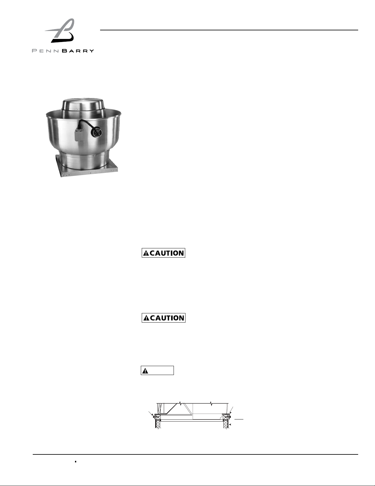
Fumex (Standard, Heat & Smoke & Restaurant Exhaust)
Centrifugal Roof & Wall: Direct & Belt Drive Exhausters
Description
Designed for severe service removing foul air from industrial and commercial buildings,
laboratory fume hoods. Housing and wheel constructed of aluminum; heat and smoke
removal utilizes a steel wheel. Motor compartment externally cooled and located out of
the discharge airstream. Power ventilators suitable for Restaurant Exhaust Appliances
(YZHW) are accordingly labeled. Power ventilators suitable for smoke removal are accordingly labeled. These units require installation according to NFPA-96 standards, local codes and general practices. Up to Model 24B are available wall mounted (WFX).
DAMPERS: ROOF MOUNTING
When required, install dampers prior to
mounting the unit on the curb or frame.
Dampers are sized to t within the roof
opening. Secure using standard hardware.
If the damper is installed on the inside of the
curb, a piece of wood may be required as a
“spacer”. Do not twist or distort the damper
frame. Damper frame must be reasonably
level on all sides. Check for free operation.
If dampers are motor operated type, ascertain that proper voltage is applied on motor
terminals.
ANCHORING AND INSTALLING
THE VENTILATOR
Roof mounting may be in accordance with
the latest edition of NFPA-96 and local
codes. If not specied by codes), secure
unit to curb through pre-punched holes in
the ventilator base vertical ange (see Figure 1 below).
In order to complete some installations, spe-
cically kitchen exhaust, you will require an
18” high curb as well as a weather resistant
junction box and hinge assembly.
Guy down large units installed in areas sub-
ject to high winds or unusual eld con-d it
ions. If the installer removes any ventilator
parts to facilitate installation or electrical
connection, reassemble all parts by replacing all spacers, washers, nuts, bolts, fasteners and components exactly as they were
found prior to removal. Draw all fasteners
tight and secure.
Roof
Curb
Receiving and Handling
PennBarry fans are carefully inspected before leaving the factory. When the unit is
received, inspect the carton for any signs
of tampering. Inspect the unit for any damage that may have occurred during transit
and check for loose, missing or damaged
parts. Mishandled units can void the warranty provisions. If units are damaged in
transit, it is the responsibility of the receiver to make all claims against the carrier.
PennBarry is not responsible for damages
incurred during shipment.
Avoid severe jarring and/or dropping.
Handle units with care to prevent damage
to components or nishes. If the unit is
scratched due to mishandling, the protective coating may be damaged. Incorrect
lifting may damage the fan and void the
warranty.
Storage
Long-term storage requires special attention. Store units on a level, solid surface,
preferably indoors. If outside storage is
necessary, protect the units against moisture and dirt by encasing the cartons in
plastic or in some similar weatherproof
material. Periodically inspect units and
rotate wheels to spread bearing lubricant.
Failure to rotate wheels results in reduced
bearing life and may void the manufacturer’s warranty. If the unit will be stored
for an extended time, remove belts. Belts
which remain under tension in a stationary
position for extended periods are likely to
have a reduced operating life.
Unpacking
Place the carton in an upright position and
remove the staples or use a sharp (knife
edge) tool to carefully cut or scribe the
sealing tape on both sides at the top of
the carton. Open carton aps. Remove
any cardboard and wooden ller pieces,
as well as loose components or accessories shipped with the unit.
Carefully remove the unit from the carton.
Inspect the unit for any damage that may
have occurred during transit and check for
loose, missing or damaged parts.
Installation
When the unit is installed on a sloped roof,
suitable footing and/or other safety devices
must be provided around the ventilator for
normal maintenance. Depending upon the
site conditions, the hinging of the ventilator
off the curb during maintenance should be
either parallel to the roof ridge or toward the
roof ridge, but NOT away from the ridge.
NFPA-96 recommends t h at da m p ers
sh o u ld not be installed when exhauster is
used for the removal of smoke and grease
laden vapors from commercial cooking
equipment. Consult state and local codes for
detailed requirements.
NOTE
be installed per instructions on page 5.
Figure 1: Roof Curb Installation
Fastener
For instalation in high velocity hurricane zones, Unit must
Base
1401 North Plano Road, Richardson, Texas 75081
Phone: 972-234-3202 Fax: 972-497-0441
Revised MAR 09
PART #59368-0
Page 2
Operation & Maintenance Manual Fumex Centrifugal Roof & Wall: Direct & Belt Drive Exhausters
FLOATING HINGE INSTRUCTIONS
1. If any gasket is to be eld installed, this
should be completed before installing
the oating hinge. If a grease collection box will be installed, it should be
installed after installing the oating
hinge, and not on either the hinge or
handle sides of the unit.
2. If this item is provided, hardware is
included. Review gure 2 for illustrations regarding this installation. Detailed instructions should be provided
with the hinge kit, which are summarized below. The hinge kit instructions
take precedence over these instructions.
3. Take back plate and position inside
the pedestal to allow for the pedestal
metal thickness, ush with both the
top and rear vertical surfaces. Use
this plate as a template to mark the
hole locations. Drill two clearance
holes. Do this for both sides of the
pedestal.
4. Bolt both back plates in place INSIDE
the pedestal. Slide bushing over the
rear most back plate bolt.
Figure 2: Floating Hinge Installation
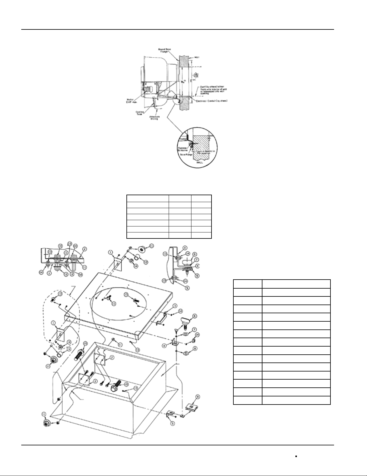
Figure 3: Wall Mount Installation
Table 1: Wall Mount Dimensions
Model E
WFX08 24 9
WFX10–WFX13 11 & 24 11 1/2
WFX8B–WFX14B 27 1/4 16 1/4
WFX16 24 40 1/4
WFX16B–WFX18B 29 1/2 20
WFX24B 35 7/8 25
DIA
Wo
5. Insert 2 bolts through pre-punched
holes on each side of the ventilator
base.
6. Position the ventilator on top of the
pedestal. Install the oating hinge
by aligning the slotted hole over the
bushing (on rear most bolt) and onto
the two bolts on the ventilator base.
Fasten with nuts and tighten. Install
nut over bushing. The forward back
plate bolt functions as a stop; nothing
is attached to it.
7. Install the lift handle and hold down
lugs to ventilator base through the
pre-punched holes.
8. Using the hold down lug as a template, drill on both sides of the pedestal to install wing nut hardware.
When installed, tighten rmly.
WALL MOUNTING
Fumex fans are available with round
bases to facilitate wall mounting through
size 24B (WFX), If installing these units,
ensure the wall mounting surface is leak-
SQ
free. To assure weather-tightness, coat the
entire rear side (that portion which mates
with the wall) of the mounting ange with
a suitable caulking compound or an approved waterproof mastic sealer.
On masonry walls, attach the base ange
with lead cinch type anchors and a nonferrous bolt. On sidings, use nonferrous
lag bolts. Washers are recommended to be
used under the bolt heads.
Table 2: Floating Hinge Parts List
Ref. # Description
1 Floating Hinge
2 Back Plate
3 Lifting Angle
4 Hold Down Lug (short)
5 Bottom Lug (long)
6 Thumb Screen
7 Plastic Washer for Screw
8 Metal Hold Washer for Screw
9 Retaining Clip
10 3/8”-16 X 1 1/2 Whiz Bolt
11 3/8”-16 Whiz Nut
12 1/2-3/8 X 3/8 Lg. Bushing
13 10-32 X 1/2 Whiz Bolt
14 10-32 Whiz Nut
2 PENNBARRY 1401 North Plano Road, Richardson, Texas 75081
Phone: 972-234-3202 Fax: 972-497-0441
Page 3
Fumex Centrifugal Roof & Wall: Direct & Belt Drive Exhausters
Operation & Maintenance Manual
Positioning and Running
Power Lines
ROOF MOUNTING
Power is normally brought from within
the building through proper conduit lines
and placed inside the curb. Feed power
through the ventilator to the (Disconnect
Switch or Junction Box) motor. Wiring can
be brought through the cooling tube from
the outside; this is the method to be used
for NFPA96, as well as smoke controll
systems installations if an external disconnect junction box is not already provided.
WALL MOUNTING
Power is normally brought up from within
the building through proper conduit lines to
the wall opening, then fed to the (Disconnect Switch or Junction Box) motor. Wiring
can be brought through the cooling tube
from the outside; this is the method to be
used for NFPA96 installations if an external disconnect junction box is not already
provided.
Start-Up and Operation
Carefully inspect the unit before startup.
All motor bearings should be properly lubricated and all fasteners should be securely tightened. Rotate centrifugal wheel
by hand to insure free movement.
Before placing hand on centrifugal wheel
or belts, lock out the power source. Check
all set-screws and keys. Tighten when
necessary. Check the condition of belts
and the amount of tension prior to start-up.
DO NOT overtighten, as bearing dam-age
will occur.
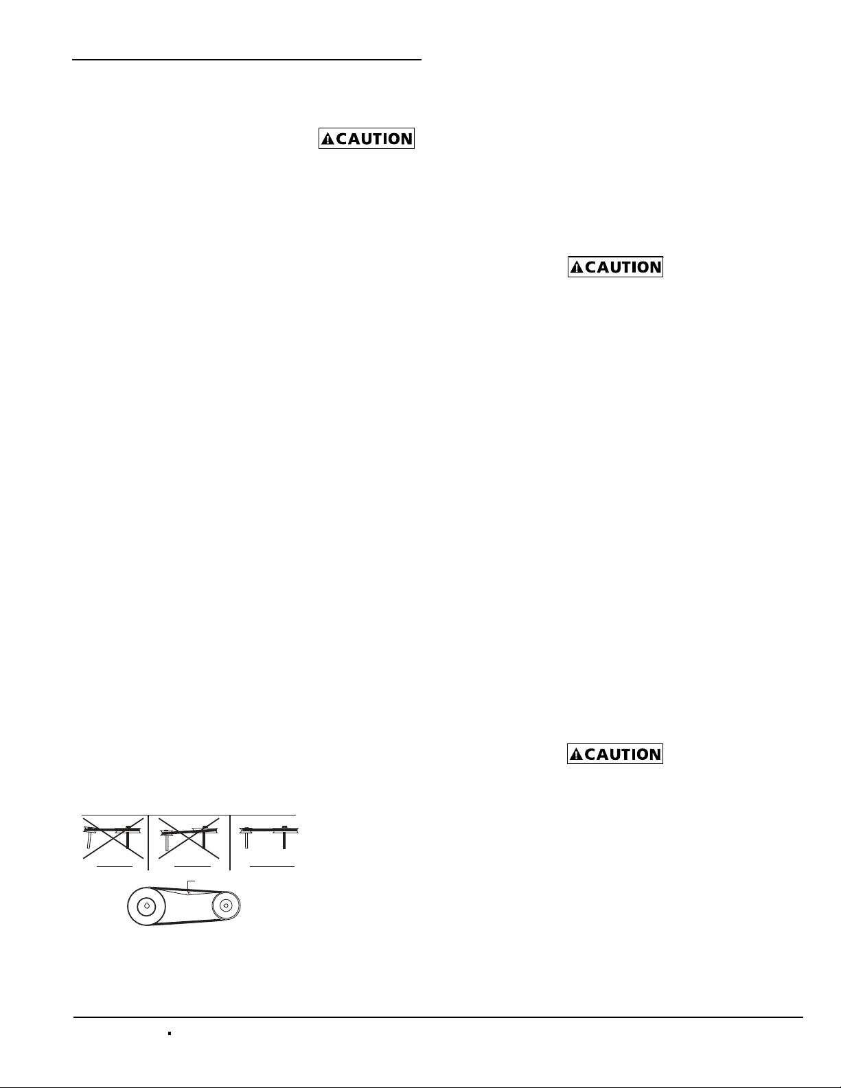
Recommended belt tension should permit
deection of 1/64” per inch of span. Exercise extreme care when adjusting belts as
not to mis-align pulleys. Any misalignment
will cause a sharp reduction in belt life and
can produce excess belt noise. (see Figure 4). On units equipped with two groove
pulleys, adjust all belts with equal tension.
Figure 4: Pulley Alignment & Tension
WRONG WRONG CORRECT
Not to exceed 1/64” per inch of span
Belts must be adjusted after approx. 40
hours of operation.
Whenever belts
are removed or
installed, never force belts over pulleys
without loosening motor rst to relieve
belt tension.
Make sure inlets and approaches to the
unit are free from obstruction. To assure
maximum air movement, make sure adequate supply air is available to ventilated
space.
When power lines are brought up to the
unit, provide a generous amount of slack
to allow for motor adjustments and to permit movement of motor for belt tension adjustments. Ground motor adequately and
securely. Protect power lines from sharp
objects. Do not kink power line or permit it
to contact hot surfaces, chemicals, grease
or oil. Use only UL recognized electrical
parts, rated for proper voltage, load and
environment.
Before putting fan into operation, complete
the following check list:
a. Turn off and LOCK OUT
the power source.
b. Make sure installation
is in accordance with manufacturer’s
instructions.
c. Check and tighten all fasteners.
d. Spin centrifugal wheel
to see if rotation is free.
e. Check all set-screws and keys:
tighten if necessary.
f. Torqued set screws have a colored
Torque Seal mark indicating the correct torque has been applied.
g. Check belt or direct drive coupling
for alignment
h. Check belt for proper belt tension
i. Make sure there is no foreign or
loose material in ductwork leading to
and from fan or in the fan itself.
j. Properly secure all safety guards.
k. Secure all access doors to fan
and ductwork.
l. Check line voltage with
motor nameplate.
m. Check wiring.
On single phase mot ors, t he t ermin al block
must be set up in accordance with the nameplate instructions and/or wiring diagram. This
set up must match the line voltage. If the motor is multi-speed or multi-voltage, the winding leads must be grouped and connected as
shown on the motor wiring diagram. The line
voltage must correspond with proper grouping of motor leads. The wiring diagram must
be followed explicitly or serious motor or
starter damage will occur.
Do not operate models from line frequencies higher than 60Hz + or -5% with standard motors.
The ventilator has been checked at the factory prior to shipment for mechanical noises. If mechanical noises should develop:
a. Check rotating component for
adequate clearance and direction of
rotation. See page 6 for the wheel
alignment procedure. See top of plate
for wheel direction.
b. Check proper belt tension
and pulley alignment.
c. Check installation and anchoring.
d. Check fan bearings.
e. Check that cooling tube is in place
and well sealed.
Incorrect rotation overloads motor severely
and results in serious motor damage. To
change rotation of three phase units, interchange any 2 of the 3 line leads. On single
phase units, change the terminal block
set-up following the wiring diagram on the
motor.
1401 North Plano Road, Richardson, Texas 75081
Phone: 972-234-3202 Fax: 972-497-0441
PENNBARRY 3
Page 4
Operation & Maintenance Manual Fumex Centrifugal Roof & Wall: Direct & Belt Drive Exhausters
f. Check motor and bearing tempera-
ture for excessive heat.
Use care when touch-
ing the exterior of an
operating motor. Modern motors normally
run hot. They are designed to operate at
higher temperatures. This is a normal condition but they may be hot enough to be
painful or injurious to the touch.
If any problem is indicated, TURN OFF
POWER TO UNIT IMMEDIATELY. Lock
out the electrical supply, check carefully
for the cause of the trouble and correct
as needed. Even if the fan appears to be
operating satisfactorily, shut down after a
brief period and check all fasteners, setscrews and keys for tightness.
During the rst eight (8) hours of operation, check the fan periodically for excessive vibration or noise. At this time, also
check motor input current and motor
bearing temperatures to insure that they
do not exceed manufacturer’s recommendations. After eight hours of satisfactory
operation, shut down the fan and lock out
the electrical power to check the following
items and adjust if necessary:
a. All set-screws, keys and fasteners.
b. Belt alignment.
c. Belt tension.
Maintenance
Do not attempt maintenance on the fan
until the electrical supply has been completely disconnected. If a disconnect
switch has not been provided, remove all
fuses from the circuit and lock the fuse
panel so they cannot be accidentally replaced.
Lubrication is a primary maintenance responsibility. Check all bearings periodically. Inspect belts for tightness. If the fan
is installed in a corrosive or dirty atmosphere, periodically clean the centrifugal
wheel, inlet, motor housing and other
moving parts.
FAN SHAFT LUBRICATION
Fan shaft bearing pillow blocks are furnished in either the pre lubricated sealedfor-life type or the greasable type. The
prefabricated type requires no servicing
for 7 to 10 years of normal use. Follow the
lubricating schedule recommended by the
factory. This practice should not supersede any safety considerations.
Use low pressure
grease guns only. High
pressure guns tend to blow out or unseat
bearing seals, leaving the bearing open to
collect grime, dust and foreign particles.
LUBRICATION SCHEDULE
Always follow the bearing manufacturer’s
recommended lubrication schedule. If
none is available use the following general schedule.
a. Under average conditions where
ambient temperatures do not exceed
120°F, lubrication is required 1 to 2
times a year.
b. Under dirt laden atmosphere where
there is a temperature range of 120°F
to 150°F, lubrication is required from
3 to 6 times a year.
c. Under extreme temperature condi-
tions and extremely dirty atmospheres, lubrication should be scheduled at least once or twice a month.
d. Belt drive units maximum tempera-
ture should not exceed 160°F.
Direct driven models have temperature range stamped on motor.
MOTOR LUBRICATION
In general, standard motors are furnished
with prelubricated, sealed-for-life ball bearings which require no lubrication for 7 to
10 years of normal service. Where motors
have been ordered with greasable bearings, these bearings are factory lubricated
and require no attention for one year under
normal conditions. If grease relief ttings
are provided, remove them when perform-
ing maintenance to allow grease to ow
out. Whenever possible, apply grease
while the motor is running. This practice
should not supersede any safety considerations. DO NOT OVER-GREASE, as most
lubricants deteriorate motor windings,
thereby reducing motor life.
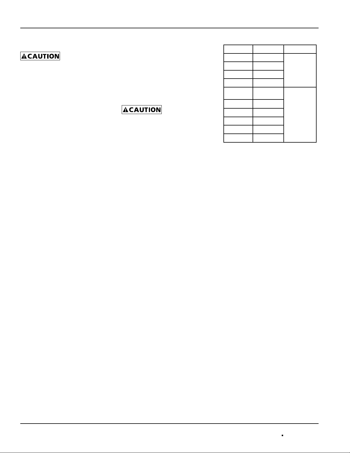
Table 3: Recommended Lubricants
Manufacturer Product Temp. Range
BP LG-#P-1
Gulf Gulfcrown EP-1
Imperial Oil Unirex EP-1
Shell Alvania R-1
BP
Gulf Gulfcrown EP-2
Imperial Oil Unirex EP-2
Shell Alvania R-3
Sun Oil Sun Prestige 42
Texaco Regal AFB2
Energrease,
MPMK11
Below 32°F
(0°C)
32°F to 150°F
(0°C to 66°C)
Guards
All fans have moving parts which require
guarding in the same way as other moving
machinery.
Where the fan is accessible to untrained personnel or the general public, use maximum
safety guards, even at the cost of some
performance loss. Unprotected fans locat-
ed less than 7’ above the oor also require
guarding as specied in the Occupational
Safety and Health Act (OSHA). PennBarry
strongly recommends the use of guards on
all exposed nonducted fans, ceiling and wall
mounted.
Centrifugal fans may be connected directly
to ductwork which will prevent contact with
the internal moving parts, but when the inlet or outlet is exposed, install a suitable
guard.
Replacement Parts
Replace parts with components which duplicate original parts correctly. Incorrectly
sized shafts, belts, pulleys, etc.
can damage the fan.
Spare or replacement parts and prices are
available upon request. Please supply the
following information: Factory Order Number, Customer’s Name and Order Number
and Date. If this information is not available,
furnish a complete description of the part required. Names of parts are shown on page 7.
To order motors provide the HP, RPM, voltage, phase, hertz and type of enclosure.
4 PENNBARRY 1401 North Plano Road, Richardson, Texas 75081
Phone: 972-234-3202 Fax: 972-497-0441
Page 5

Operation & Maintenance Manual Fumex Centrifugal Roof & Wall: Direct & Belt Drive Exhausters
Typical Concrete Slab Roof Installation
Typical Steel Framed Roof Installation
Typical Wood Framed Roof Installation
Installation Notes: All four sides of curb and base are anchored identically.
Curb Notes: 18 gauge galvanized steel minimum, maximum height 18”
5 PENNBARRY 1401 North Plano Road, Richardson, Texas 75081
Phone: 972-234-3202 Fax: 972-497-0441
Page 6

Fumex Centrifugal Roof & Wall: Direct & Belt Drive Exhausters
Wheel Alignment Procedures
Figure 5: Wheel Alignment
Operation & Maintenance Manual
Front to Back
Side to Back
The wheel position is preset at factory and must rotate freely.
However, movement may occur due to rough handling prior to instal-
lation and realignment may be necessary. If eld correction is required
follow these procedures:
1. If “Front to Back” adjustment is required, loosen both motor frame
support angles (four nuts), relocate frame and retighten.
2. If “Side to Side” adjustment is required, loosen both bearings
(four nuts), relocate and retighten.
3. If “Vertical” adjustment is required, loosen both set screws
on the wheel hub (accessible from the bottom side of the unit),
raise or lower the wheel and retighten.
1401 North Plano Road, Richardson, Texas 75081
Phone: 972-234-3202 Fax: 972-497-0441
PENNBARRY 6
Page 7

Operation & Maintenance Manual Fumex Centrifugal Roof & Wall: Direct & Belt Drive Exhausters
Troubleshooting Checklist
Symptom Possible Cause(s) Corrective Action
1. Defective or loose motor bearings 1. Replace motor with same frame size, RPM, HP
2. Ventilator base not securely anchored 2. Reset properly
Excessive noise
Fan inoperative
Insufcient airow
Water leaking
into ductwork
or collection of
grease under fan
3. Loose or unbalanced wheel/propeller 3. Tighten screws, remove build-up,
4. Misaligned pulleys or shaft 4. correct alignment
5. Loose or damaged wheel/propeller 4. Replace wheel/propeller
6. Wheel running in wrong direction 6. Reverse direction
1. Blown fuse or open circuit breaker 1. Replace fuses or circuit breaker
2. Loose or disconnected wiring 2. Shut off power and check wiring
3. Defective motor 3. Repair or replace motor
4. Broken belts 4. Replace belts
1. Open access doors or loose sections of ducts 1. Check for leakage
2. Clogged lters 2. Clean or replace lters
3. Operation in wrong direction 3. Correct rotation of wheel
4. Insufcient make-up air direction 4. Add make-up fan or louver opening
5. Fan speed to low 5. Speed fan up by adjusting varaible pitch pulley
on motor shaft
1. Fan installed with slope in the wrong direction
2. Clogged drain spout 2. Clean drain spout
3. Cooling tube or motor dome top removed 3. Install new cooling tube with gasket and dome top
balance wheel/propeller
for proper connections
1. Slope should be tted in the direction of the
drainage opening or grease collection box and drain
spout
4. Grease container full 4. Empty grease box
1. Belt slippage 1. Adjust tension or replace bad belts
2. Overvoltage or under voltage 2. Contact power supply company
3. Operation in wrong direction 3. Reverse direction of motor4. Fan speed too high
4. Slow down fan by opening variable pitch pulley on motor shaft
Motor overheating
Note: Care should be taken to follow all local electrical, safety and building codes. Provisions of the National Electric Code (NEC), as well as the Occupational Safety and Health Act (OSHA) should
be followed.
All motors are checked prior to shipment. If motor defects should develop, prompt service can be obtained from the nearest authorized service station of the motor manufacturer while under warranty. Exchange, repair or replacement will be provided on a no
charge basis if the motor is defective within the warranty period. The PennBarry representative in your area will provide a name and
address of an authorized service station if requested. WARNING: Motor guarantee is void unless overload protection is provided in
motor wiring circuit.
7 PENNBARRY 1401 North Plano Road, Richardson, Texas 75081
5. Incorrect motor (service factor 1.0, factors (1.15 or higher) with 40 degrees ambient
low ambient temperature)
6. Blocked cooling tube or leaky gasket 6. Remove blockage and seal cooling tube in place
7. Insufcient airow to kitchen hood fan operating 7. Check airow under hood and adjust
on low speed with kitchen in full operation. kitchen equipment output
8. Undersized motor 8. Check motor ratings with catalog speed
5. Replace motor with correct one, NEMA service
and air capacity chart
Phone: 972-234-3202 Fax: 972-497-0441
Page 8

Fumex Centrifugal Roof & Wall: Direct & Belt Drive Exhausters
Operation & Maintenance Manual
Parts Lists & Dimensions
Direct Drive
Figure 6: FX08RS, 10RS, 11RS, 11Q Figure 7: FX13RSV, 13Q Figure 8: FX16RSV, Q1, Q2
Direct Drive Parts List
1. Hood Apron 6. Base Venturi 11. Wire Clip 16. Bushing 21. Gasket
2. Hood Top 7. Base (Round for WFX) 12. Screen (Optional) 17. Screen Clip 22. Cotter Pin
3. Top Plate 8. Discharge Apron 13. Motor 18. Acorn Nut 23. Drain Spout
4. Brace 9. Apron Venturi 14. Cooling Tube 19. 1/4 - 20 Nut 24. Down Spout
5. Conduit Pipe 10. Wheel 15. Clg. Tube Gasket 20. Clip
Part Description
1 Wind Band (2 pcs. FMX50B)
2 Discharge Apron
3 Cooling Tube
4 Cooling Tube Gaskets
5 Motor Hood Lid
6 Motor Hood
7 Motor & Bearing Frame
8 Anti-Vibration Mounts
9 Top Plate
10 Bird Guard (Optional)
11 Support Wires
12 Support Wire Mounting Clips
13 Conduit Guide
14 Venturi
15 Base (Round for WFX)
16 Fan Pulley
17 Belt
18 Motor Pulley
19 Motor
20 Bearings
21 Shaft
22 Centrifugal Wheel
23 Main Fastening Braces
Figure 9: FX08B-FX36B Figure 10: FMX50B
Fan Size 8 10 11 13 16 08B 10B 12B 13B(H) 14B 16B 18B(H) 24B(H) 30B 36B 50B
Base Dimensions 18.5 18.5 18.5 18.5 20.5 24.75 24.75 24.75 24.75 24.75 28.50 28.50 33.50 36.50 44.50 59.00
All dimensions are in inches. “E”- (outside curb dimension should be 1” smaller than inside fan base dimension)
1401 North Plano Road, Richardson, Texas 75081
Phone: 972-234-3202 Fax: 972-497-0468
Direct Drive Models Belt Drive Models
PENNBARRY 8
Page 9

Operation & Maintenance Manual Fumex Centrifugal Roof & Wall: Direct & Belt Drive Exhausters
Direct Drive - Explosion Proof Motor
Spun Aluminum Centrifugal Roof Exhauster
PUNCH OR DRILL HOLE FOR CONDUIT
PATH. HOLE MUST BE SEALED OR
CAULKED TO PREVENT WATER ENTRY.
RIGID CONDUIT OR I.M.C. (INTERMEDIATE
METAL CONDUIT) PER N.E.C. AND/OR
LOCAL CODES. (BY OTHERS)
*NOTE- ALL WIRING MUST BE PROVIDED BY A
LICENSED ELECTRICIAN FAMILIAR WITH
EXPLOSION PROOF WIRING PRACTICES AND
REGULATIONS, USING COMPONENTS
APPROPRIATE TO THE SPECIFIC INSTALLATION
AND N.E.C. AND/OR LOCAL CODES.
Legend
1. Motor Dome
2. Motor Hood Top (For Exp. Motor)
3. Top Plate
4. Discharge Apron
5. Structural Support Braces
6. Motor Mounting Plate
7. Motor (Exp. Motor)
8. Centrifugal Fan Wheel with Cooling
Vanes
9. Spun Venturi
10. Mounting Base
11. Conduit Guide (Not for Exp. Motor)
Dimensional Data
CLOSE NIPPLE AND UNION DIRECTLY
OUT OF MOTOR.
N.E.C. SPECIFIES A SEAL WITHIN 18”.
12. Drain Spout (Models FX13 and
FX16)
13. Cooling Tube (Models FX13 and
FX16)
14. Aluminum Bird Screen (Optional)
FX08Q FX10Q FX11Q FX13Q FX16Q
DIA.
L
H
† Outside dimension of curb should be 1 1/2” less than ‘E’ dimension
EXP. MOTOR
SQ.
E†
SQ.
Ro
25 25 25 25 1/2 30 1/2
18 19 19 19 26 716
18 1/2 18 1/2 18 1/2 18 1/2 20 1/2
9 11 1/2 11 1/2 11 1/2 16 1/4
All dimensions in inches.
Material: Spun Aluminum Housing
This drawing illustrates our understanding of order requirements. When approved, it represents details for fabrication, as such, PennBarry will not be responsible for revisions in the eld or other
changes after release for fabrication. Published and protected by PennBarry, Richardson, TX. All rights reserved. May not be reproduced partially or in full without permission from the publisher.
No rights conveyed to manufacture partially or in full, use or sell either the method of construction represented or any invention in any way related thereto.
9 PENNBARRY 1401 North Plano Road, Richardson, Texas 75081
Phone: 972-234-3202 Fax: 972-497-0441
Page 10

Fumex Centrifugal Roof & Wall: Direct & Belt Drive Exhausters
Wiring Harness - Disconnect Device
O.D.P. Motors (ITW Harness) 115/220 Single Phase
Operation & Maintenance Manual
O.D.P. MOTOR
JUNCTION BOX
COVER
POWER LEADS
8” LONG
JUNCTION BOX
4 TERMINAL
SOCKET
JUNCTION
BOX
WITH CONNECTOR
JUNCTION
BOX
COVER
4 TERMINAL
WIRING HARNESS
(FROM MOTOR)
FAN SHAFT
CONDUIT
GUIDE
WIRING HARNESS WITH CONNECTOR
ELECTRICAL CONNECTIONS
Connect motor per nameplate to correct power supply. Install
SOCKET
all wiring, protection and grounding in accordance with National
Electrical Code and local requirements. Follow all local electrical
and safety codes, as well as the National Electrical Code (NEC)
and the Occupational Safety and Health Act (OSHA).
WIRING INSTRUCTIONS
CAUTION: When bringing power lines up, power MUST be off.
1. Bring power lines up to motor compartment thru conduit guide.
2. Remove junction box cover so that power leads are exposed.
3. Remove one knock-out, attach connector and run power lines
from source into junction box.
4. Terminal socket has two 8” long pigtails already stripped. Make
connection to power lines using proper size wire nuts and fold
wires back into box.
5. Replace junction box cover and secure in place with screw.
6. Plug harness connector (from motor) into terminal socket at end
of junction box. Unit is now ready to test.
MOTOR SUPPORT
PLATE
TOP PLATE
BEARINGS
This drawing illustrates our understanding of order requirements. When approved, it represents details for fabrication, as such, PennBarry will not be responsible for revisions in the eld or other
changes after release for fabrication. Published and protected by PennBarry, Richardson, TX. All rights reserved. May not be reproduced partially or in full without permission from the publisher. No
rights conveyed to manufacture partially or in full, use or sell either the method of construction represented or any invention in any way related thereto.
1401 North Plano Road, Richardson, Texas 75081
Phone: 972-234-3202 Fax: 972-497-0441
PENNBARRY 10
Page 11

Operation & Maintenance Manual
Fumex Centrifugal Roof & Wall: Direct & Belt Drive Exhausters
Limited One Year Warranty
What Products Are Covered
PennBarry Fans and Ventilators (each, a “PennBarry Product”)
One Year Limited Warranty For PennBarry Products
PennBarry warrants to the original commercial purchaser that the PennBarry Products will be free from defects in material and workmanship for a period of one (1) year from the date of shipment.
Exclusive Remedy
PennBarry will, at its option, repair or replace (without removal or installation) the affected components of any defective PennBarry
Product; repair or replace (without removal or installation) the entire defective PennBarry Product; or refund the invoice price of the
PennBarry Product. In all cases, a reasonable time period must be allowed for warranty repairs to be completed.
What You Must Do
In order to make a claim under these warranties:
1. You must be the original commercial purchaser of the PennBarry Product.
2. You must promptly notify us, within the warranty period, of any defect and provide us with any substantiation that we may reasonably request.
3. The PennBarry Product must have been installed and maintained in accordance with good industry practice
and any specic PennBarry recommendations.
Exclusions
These warranties do not cover defects caused by:
1. Improper design or operation of the system into which the PennBarry Product is incorporated.
2. Improper installation.
3. Accident, abuse or misuse.
4. Unreasonable use (including any use for non-commercial purposes, failure to provide reasonable and necessary maintenance as
specied by PennBarry, misapplication and operation in excess of stated performance characteristics).
5. Components not manufactured by PennBarry.
Limitations
1. In all cases, PennBarry reserves the right to fully satisfy its obligations under the Limited Warranties by refunding the invoice
price of the defective PennBarry Product (or, if the PennBarry Product has been discontinued, of the most nearly comparable
current product).
2. PennBarry reserves the right to furnish a substitute or replacement component or product in the event a PennBarry Product or
any component of the product is discontinued or otherwise unavailable.
3. PennBarry’s only obligation with respect to components not manufactured by PennBarry shall be to pass through
the warranty made by the manufacturer of the defective component.
General
The foregoing warranties are exclusive and in lieu of all other warranties except that of title, whether written, oral or im-
plied, in fact or in law (including any warranty of merchantability or tness for a particular purpose).
PennBarry hereby disclaims any liability for special, punitive, indirect, incidental or consequential damages, including
without limitation lost prots or revenues, loss of use of equipment, cost of capital, cost of substitute products, facilities or
services, downtime, shutdown or slowdown costs.
The remedies of the original commercial purchaser set forth herein are exclusive and the liability of PennBarry with respect to the
PennBarry Products, whether in contract, tort, warranty, strict liability or other legal theory shall not exceed the invoice price charged
by PennBarry to its customer for the affected PennBarry Product at the time the claim is made.
Inquiries regarding these warranties should be sent to: PennBarry, 1401 North Plano Road, Richardson, TX 75081.
11 PENNBARRY
1401 North Plano Road, Richardson, Texas 75081
Phone: 972-234-3202 Fax: 972-497-0441
 Loading...