

Page 1
SWP
(Models SWP08 through SWP20)
OPERATION & MAINTENANCE MANUAL
IMPORTANT! Read before proceeding!
Read carefully before attempting to assemble, install, operate or maintain
the product described. Protect yourself and others by observing all safety
information. Failure to comply with instructions could result in personal injury
and/or property damage! Retain instructions for future reference.
1
Page 2

TABLE OF CONTENTS
INTRODUCTION 3
INSTALLATION 4-6
START-UP AND OPERATION 7
MAINTENANCE 8
DIMENSIONAL DATA 9
FAN EXPLODED VIEW 10
WALL MOUNTING SLEEVE ASSEMBLY 11
WEATHER SHIELD ASSEMBLY 12
DAMPER GUARD ASSEMBLY 13
TROUBLESHOOTING CHECKLIST 14
2
www.PennBarry.com
Page 3
INTRODUCTION
Storage
Long-term storage requires special attention. Units should be stored on a level, solid surface, preferably indoors. If outside storage
is necessary, protect the units against moisture and dirt by encasing the cartons in plastic or some similar weatherproof material.
Unpacking
Place carton in an upright position and remove staples or use a sharp (knife edge) tool to CAREFULLY cut or scribe the sealing
tape on both sides at the top of the carton. Open carton aps. Remove any cardboard and wooden ller pieces, as well as loose
components or accessories shipped with the unit.
Carefully remove the unit from the carton. Inspect the unit for any damage that may have occurred during transit and check for
loose, missing or damaged parts.
Receiving and Handling
PennBarry fans are carefully inspected before leaving the factory. When the unit is received, inspect the carton for any signs of
tampering. Inspect the unit for any damage that may have occurred during transit and check for loose, missing or damaged parts.
Mishandled units can void the warranty provisions. PennBarry is not responsible for damages incurred during shipment.
www.PennBarry.com
3
Page 4
INSTALLATION
SWP is for general ventilating use only; do not use to exhaust hazardous or explosive materials and vapors.
CAUTION
Any accessories which have been provided “knocked-down” can be assembled per illustrations provided (pages 9 - 11).
Remove internal protective shipping trays and llers. Check for and remove any loose hardware or particles from the inside of the
fan housing. Disconnect motor cord and plug from internal terminal box and receptacle.
Avoid severe jarring and/or dropping. Handle units with care to prevent damage to components or special nishes.
LOCATION AND GUARDS
All fans have moving parts which require guarding in the same way as other moving machinery. Where the fan is accessible to
untrained personnel or the general public, use maximum safety guards, even at the cost of some performance. Unprotected fans
located less than 7’ above the oor require guarding as specied in the Occupational Safety and Health Act (OSHA). UL listed fans,
to maintain their personal safety listing, must be installed not less than 10 feet above the oor. PennBarry recommends the use of
guards on all exposed non-ducted fans.
INSTALLING THE PANEL FAN
Wall openings must be square and must be a minimum of 1/2” greater than the outside dimension of the panel fan housing, when
recessed within the wall. Level and securely anchor the fan to the wall through holes pre-drilled in the mounting ange. Use the type,
size and number of fasteners suitable to the unit size and wall construction. If the contractor removes ventilator parts, reassemble
by placing all spacers, washers, nuts, bolts, fasteners and components exactly as they were prior to removal. Tighten and secure all
fasteners.
Before attempting any repair or installation work, be certain that all power to the motor and electrical accessories is
CAUTION
ELECTRICAL CONNECTIONS
1. Connect motor, per nameplate, to correct power supply.
2. Install all wiring, protection and grounding in accordance with national electrical code and local requirements.
3. Follow all local electrical and safety codes, as well as the National Electrical Code (NEC) and the Occupational Safety and Health
Act (OSHA).
4. In order to prevent motor failure when speed controller is used, unit must be started on high speed before turning to low speed.
CAUTION
POSITIONING AND RUNNING POWER LINES
Power is normally brought from within the building through proper conduit lines to the wall opening, and in turn to the (service
switch, if furnished, or to the) motor. When power lines are brought up to the unit, provide a generous amount of slack to allow for
motor adjustments and to permit movement of motor for belt tension adjustments. Ground motor adequately and securely. Protect
power lines from sharp objects. Do not kink power line or permit it to contact hot surfaces, chemicals, grease or oil. Use only UL
recognized electrical parts, rated for proper voltage, load and environment.
turned o and locked in the o position.
Follow all local electrical, safety and building codes, the provisions of the National Electrical Code and the Occupational
Safety and Health Act.
4
www.PennBarry.com
Page 5
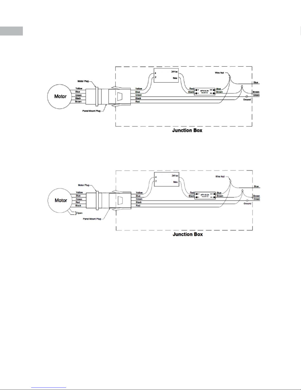
INSTALLATION
Speed
Controller
Speed
Controller
Speed
Controller
Figure 1: Internal Electrical Connections 120 V motor
Speed
Controller
Figure 2: Internal Electrical Connections 208-230/277 V motor
Speed
Controller
INSTALLING THE WALL DAMPER
When required, level and fasten the wall damper through the mounting holes provided in the damper mounting ange. Consult
Figure 1 for the proper mounting arrangements. Secure the damper to the wall opening without undue twisting which may distort
the frame. Check for free operation. If dampers are motor operated type, ascertain the proper voltage is present on motor terminals.
The fan is now ready for service.
www.PennBarry.com
5
Page 6

INSTALLATION
Minimum Clearance between Fan and Shutter – Figure 4
Model
Dimension (D)
8 10 12 14 16 18 20
SWP 6 6 6 6 6 6 6
Figure 3: Typical Wall Sleeve Installation
Figure 4: Typical Wall Sleeve and Damper Installation
D
Figure 5: Other Typical Mounting Arrangements
Wall Shutter Recess Mounting Wall Shutter Surface Mounting Louver
6
www.PennBarry.com
Page 7

START-UP AND OPERATION
Carefully inspect the unit before start-up. All motor bearings should be properly lubricated, and all fasteners should be securely
tightened. Rotate propeller by hand to ensure free movement.
Before placing hand on impeller or belts, lock out power source. Check all set-screws and keys. Tighten when necessary
CAUTION
Make sure inlets and approaches to the unit are free from obstruction. To ensure maximum air movement, make sure adequate
supply air is available. Before putting fan into operation, complete the following check list:
a. Turn o and LOCK OUT power source.
b. Make sure installation is in accordance with manufacturer’s instructions.
c. Check and tighten all fasteners.
d. Spin propeller to see if rotation is free.
e. Check all set-screws and keys; tighten if necessary.
f. Torqued set-screws have a colored Torque Seal mark indicating the correct torque has been applied.
g. Make sure there is no foreign or loose material in ductwork leading to and from fan or in the fan itself.
h. Properly secure all safety guards.
i. Secure all access doors to fan and ductwork.
j. Check line voltage with motor nameplate.
k. Check wiring.
The fan has been checked at the factory prior to shipment for mechanical noises. If mechanical noises should develop:
a. Check rotating components for adequate clearance.
b. Check installation and anchoring.
Switch on electrical supply and allow fan to reach full speed. Check carefully for:
1. Correct rotation of the impeller.
Incorrect rotation overloads motor severely and results in serious motor damage. On single phase units, change the
CAUTION
2. Check motor and bearing temperatures for excessive heat against the manufacturer’s recommendations.
CAUTION
If any problem is indicated, TURN OFF POWER TO UNIT IMMEDIATELY. Lock out the electrical supply, check carefully for the cause
of the trouble and correct as needed. Even if the fan appears to be operating satisfactorily, shut down after a brief period and check
all fasteners, setscrews and keys for tightness. During the rst eight (8) hours of operation, check the fan periodically for excessive
vibration or noise. At this time, also check motor input current and motor bearing temperatures to ensure that they do not exceed
manufacturer’s recommendations. After eight hours of satisfactory operation, shut down the fan and lock out the electrical power to
check the following items and adjust all set-screws, keys, and fasteners as necessary.
terminal block set-up following the wiring diagram on the motor.
Use care when touching the exterior of an operating motor. Modern motors normally run hot. They are designed to
operate at higher temperatures. This is a normal condition, but they may be hot enough to be painful or injurious to
the touch.
www.PennBarry.com
7
Page 8

MAINTENANCE
To reduce the risk of injury, disconnect from power supply before servicing.
CAUTION
Do not attempt maintenance on fan until the electrical supply has been completely disconnected. If a service switch has not
been provided, remove all fuses from the circuit and lock the fuse panel so they cannot accidentally be replaced.
The propeller, venturi panel, motor, and wire grill should be cleaned of dust and grease if required. Power should be disconnected
before cleaning the internal parts of the ceiling fan.
In general, standard motors are furnished with pre-lubricated, sealed-for-life ball bearings which require no lubrication.
HIDDEN DANGER
In addition to the normal dangers of rotating machinery, fans present an additional hazard in their ability to suck in not only air,
but loose material as well. Solid objects can pass through the fan and be discharged by the impeller as potentially dangerous
projectiles. Therefore, screen intake to ductwork, whenever possible, to prevent the accidental entrance of solid objects. Never
open access doors to a duct system with the fan running.
When starting the fan for the rst time, completely inspect the ductwork and interior of the fan (with power locked o), to make
certain there is no foreign material which can be sucked into or blown through the ductwork.
GUARDS
All fans have moving parts which require guarding in the same way as other moving machinery.
Where the fan is accessible to untrained personnel or the general public, use maximum safety guards, even at the cost of some
performance loss. Unprotected fans located less than 7’ above the oor also require guarding as specied in the Occupational
Safety and Health Act (OSHA).
PennBarry recommends the use of guards on all exposed non-ducted fans, ceiling and wall mounted.
8
www.PennBarry.com
Page 9

DIMENSIONAL DATA
Sizes 08 - 12
A
A
B
Sizes 14 - 20
A
B
A
Size DIM A DIM B
08 13.0 11.06
10 15.0 11.13
12 18.0 11.75
14 20.0 13.88
16 22.0 14.68
18 24.0 14.13
20 26.0 13.94
www.PennBarry.com
9
Page 10
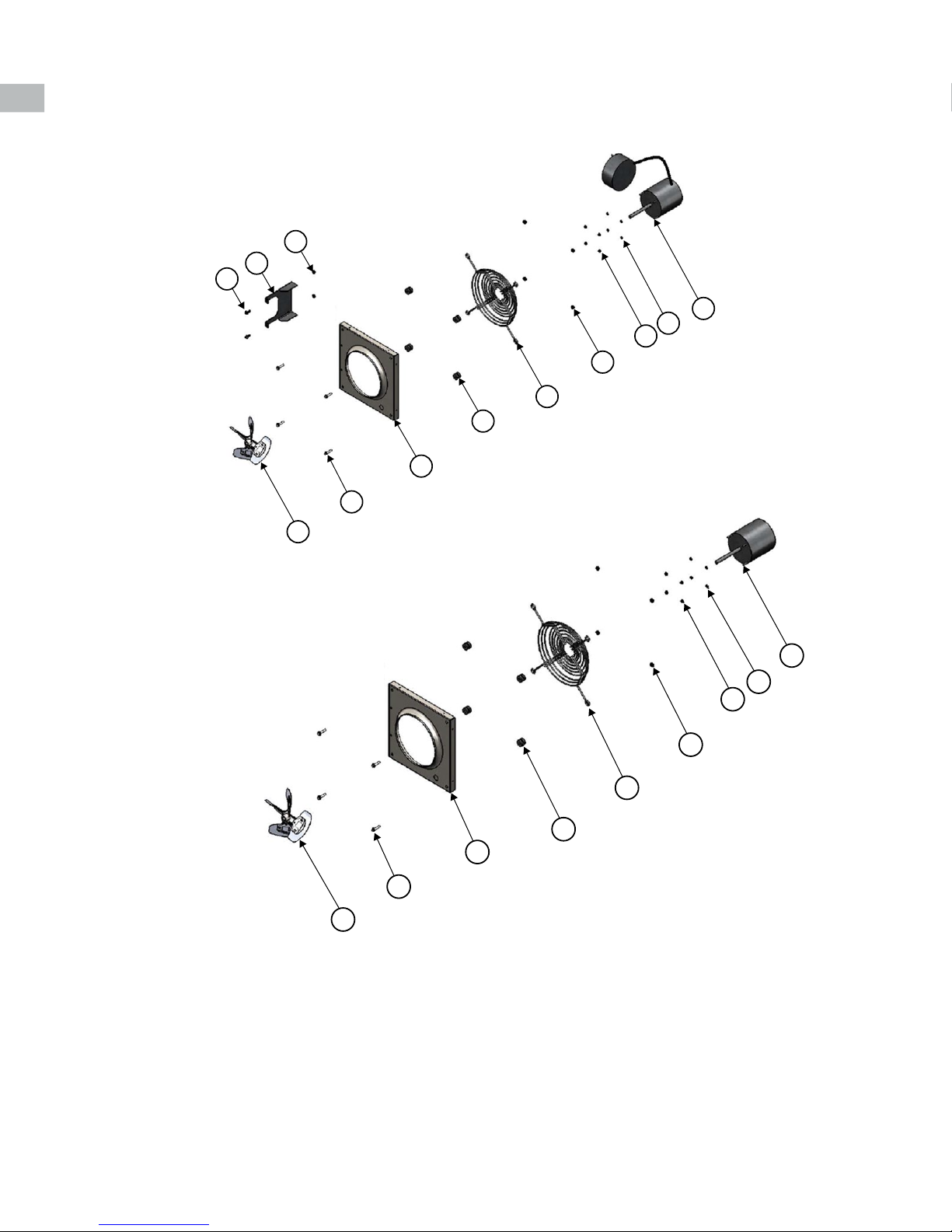
FAN EXPLODED VIEW
Parts List Sizes 08 – 12
12
11
10
6
1
5
9
8
7
4
3
2
Parts List Sizes 14 - 20
Legend
1. Propeller
2. Venturi Panel
3. Wire Guard H/W package
4. Wire Guard
5. Motor
6. ¼-20 x 1.25” Whiz Bolt
7. ¼-20 Whiz Nut
8. #8-32 Whiz Nut
9. #8 Washer
10. 10-32 x 1.00” Bolt
11. Controller Support Bracket
12. #10-32 Whiz Nut
10
5
9
8
7
4
3
2
6
1
www.PennBarry.com
Page 11
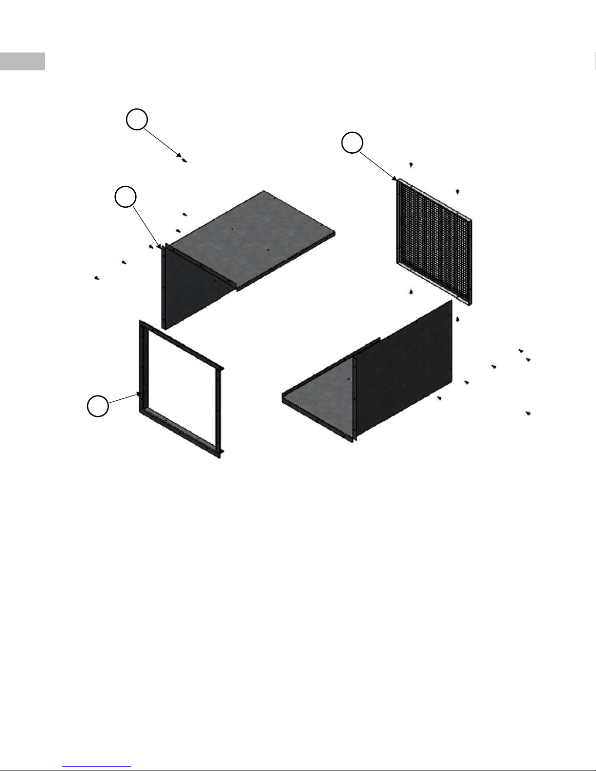
WALL MOUNTING SLEEVE ASSEMBLY
3
2
1
4
Legend
1. L Panels
2. Screen Guard
3. Hex #10 X 5/8 Self Drilling
4. Slip Flange
www.PennBarry.com
11
Page 12

WEATHER SHIELD ASSEMBLY
45 Degree Weather Hood
1
4
3
5
6
2
Legend
1. Top Panel
2. Bottom Panel
3. Left Panel
4. Right Panel
5. Screen Guard
6. Hex #10 X 5/8 Self Drilling
90 Degree Weather Hood
2
6
3
4
1
5
12
www.PennBarry.com
Page 13

DAMPER GUARD ASSEMBLY
1
2
3
4
Legend
1. L Panels Top
2. L Panels Side
3. Screen Guard
4. Hex #10 X 5/8 Self Drilling
www.PennBarry.com
13
Page 14

TROUBLESHOOTING CHECKLIST
Symptom Possible Cause(s) Corrective Action
1. Defective or loose motor bearings 1. Replace motor with same frame size, RPM, HP
2. Ventilator not securely anchored 2. Reset properly
Excessive Noise
Fan Inoperative
Insufcient Airow
Motor Overheating
Note: Care should be taken to follow all local electrical, safety and building codes. Provisions of the National Electric Code (NEC), as well as the
Occupational Safety and Health Act (OSHA) should be followed.
3. Loose or unbalanced impeller 3. Tighten fasteners, remove build-up, balance propeller
4. Loose or damaged impeller 4. Replace propeller
5. Propeller rotating in wrong direction 5. Reverse direction
1. Blown fuse or open circuit breaker 1. Replace fuses or circuit breaker
2. Loose or disconnected wiring
3. Defective motor 3. Repair motor
1. Open access doors or loose section of ducts 1. Check for leakage
2. Clogged lters 2. Clean lters
3. Operation in wrong direction 3. Correct rotation of propeller
4. Insufcient make-up air direction 4. Add make-up fan or louver opening
2. Overvoltage or under voltage 2. Contact power supply company
3. Operation in wrong direction 3. Reverse direction of motor
4. Fan speed too high 4. Use PWM controller to reduce motor speed
8. Undersized motor
2. Shut off power and check wiring for proper
connections
8. Check motor ratings with catalog speed and air
capacity chart
All motors are checked prior to shipment. If motor defects should develop, prompt service can be obtained from the nearest
authorized service station of the motor manufacturer while under warranty. Exchange, repair or replacement will be provided on
a no charge basis, if the motor is defective within the warranty period. The PennBarry representative in your area will provide a
name and address of an authorized service station if requested. WARNING: Motor guarantee is void unless overload protection
is provided in motor wiring circuit.
14
www.PennBarry.com
Page 15

PennBarry is proud to be your preferred manufacturer of commercial and industrial fans and blowers. Learn how PennBarry can assist
you in your next application by contacting your PennBarry Representative or visiting us on the web at www.pennbarry.com.
PennBarry | www.pennbarry.com | pennbarrysales@pennbarry.com | tel: 972.212.4700 | fax: 972.212.4702
PennBarry reserves the right to make changes at any time, without notice, to models, construction, specications, options and
availability. This manual illustrates the appearance of PennBarry products at the time of publication.
© 2018 PennBarry. All Rights Reserved. Revised AUGUST 2018
View the latest updates on the PennBarry website.
 Loading...