

Page 1
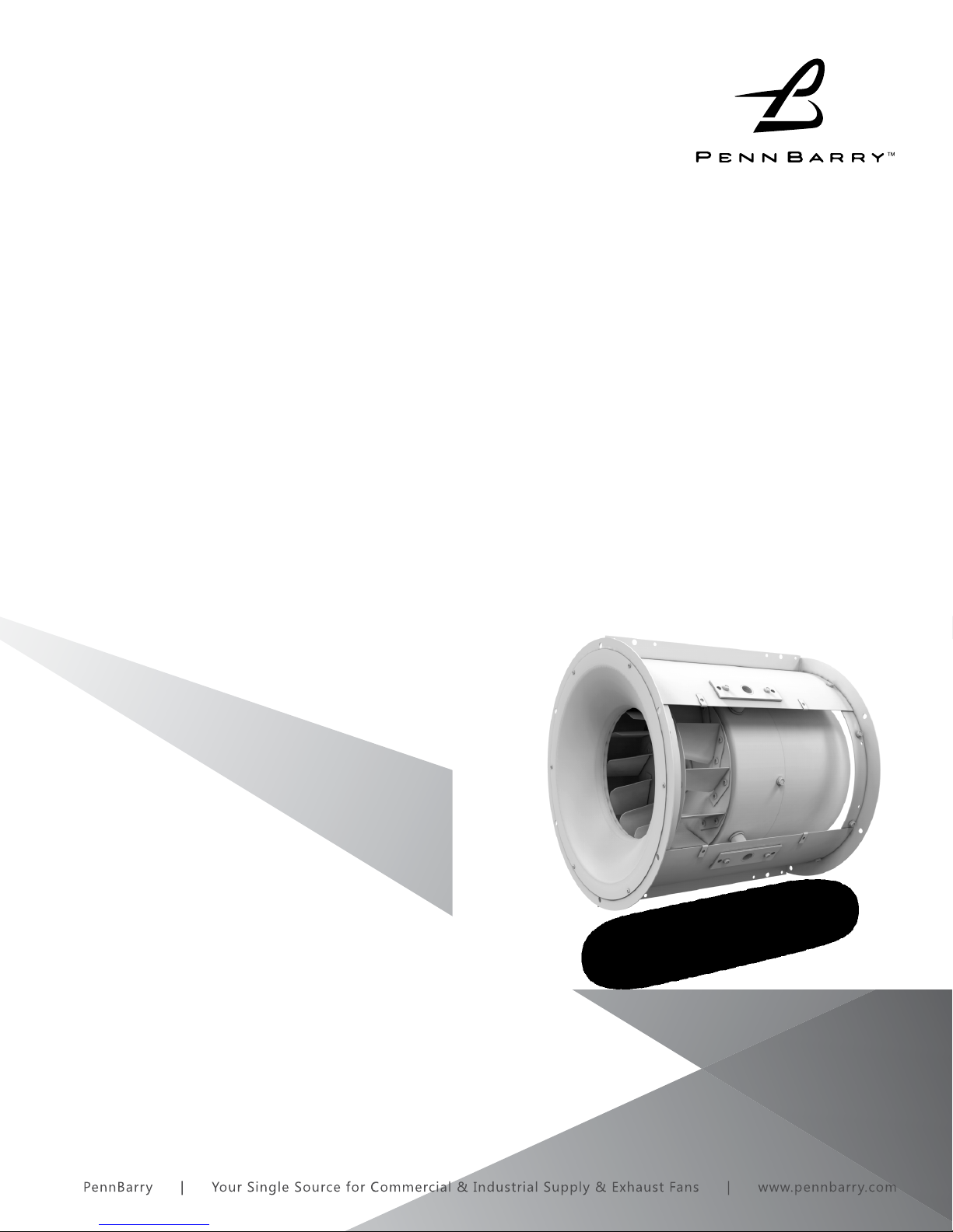
ROUND CENTREX
Centrifugal Inline Fans
OPERATION & MAINTENANCE MANUAL
IMPORTANT! Read before proceeding!
The information contained herein is, to the best of our knowledge, accurate and
applicable for proper operation and installation of the specied equipment at
the time this document entered service. Before proceeding, it is recommended
that you check for a more current version of this Installation Operation Manual
(IOM) on our website at www.pennbarry.com.
Read carefully before attempting to assemble, install, operate or maintain the
product described. Protect yourself and others by observing all safety information. Failure to comply with instructions could result in personal injury and/or
property damage! Retain instructions for future reference.
Page 2

TABLE OF CONTENTS
INTRODUCTION & INSTALLATION 3
START-UP AND OPERATION 4-5
MAINTENANCE 6
SPECIAL PURPOSE SYSTEMS, HIDDEN DANGER & GUARDS 7
PARTS REPLACEMENT 8
TROUBLESHOOTING CHECKLIST 9
2
www.PennBarry.com
Page 3

INTRODUCTION & INSTALLATION
Centrifugal Inline Fans feature motor compartment cooling to provide a long motor service life. Vanes on the motor housing serve
as a heat-sink and assist in dissipating any heat build-up. The entire operation assembly is oated on tubular supports. In belt drive
models, motors and drive pulleys are mounted on the exterior so they are readily accessible. An extra-deep spun venturi inlet mates
with a spun bottom wheel inlet plate. This smooth inlet condition ensures high capacity even at higher static pressures.
Centrifugal Inline Fan’s compact circular housing is compatible with round, oval, rectangular or square ducts. All these design
features, coupled with low outlet velocities, mean low operating noise levels with smooth, ecient airow.
PennBarry fans are carefully inspected before leaving the factory. When the unit is received, inspect the carton for any signs of
tampering. Inspect the unit for any damage that may have occurred during transit and check for loose, missing or damaged parts.
Mishandled units can void the warranty provisions. If units are damaged in transit, it is the responsibility of the receiver to make all
claims against the carrier. PennBarry is not responsible for damages incurred during shipment.
Avoid severe jarring and/or dropping. Handle units with care to prevent damage to components or nishes. If the unit is scratched
due to mishandling, the protective coating may be damaged. Incorrect lifting may damage the fan and void the warranty.
Storage
Long-term storage requires special attention. Store units on a level, solid surface, preferably indoors. If outside storage is necessary,
protect the units against moisture and dirt by encasing the cartons in plastic or in some similar weatherproof material. Periodically
inspect units and rotate wheels to spread bearing lubricant. Failure to rotate wheels results in reduced bearing life and may void
the manufacturer’s warranty. If the unit will be stored for an extended time, remove belts. Belts which remain under tension in a
stationary position for extended periods are likely to have a reduced operating life.
Unpacking
Place the carton in an upright position and remove the staples or use a sharp (knife edge) tool to carefully cut or scribe the sealing
tape on both sides at the top of the carton. Open carton aps. Remove any cardboard and wooden ller pieces, as well as loose
components or accessories shipped with the unit.
Carefully remove the unit from the carton. Inspect the unit for any damage that may have occurred during transit and check for
loose, missing or damaged parts.
Installation
Fans must be directly supported by building structure. Follow building’s blue prints carefully when installing.
Installing the Dampers
When required, dampers must be positioned and fastened to the duct or fan housing.
Positioning and Running Power Lines
Power is normally brought from within the building through proper conduit lines to the unit. It is then fed to the service switch,
if furnished, and motor. For belt driven units, lines can be fastened to the exterior of the unit housing with appropriate fastening
devices. For direct drive units, power lines are directed to the motor compartment through one of the motor cooling tubes for
connection to the motor terminals in an approved manner.
Anchoring and Securing the Ventilator
REX fans are designed for all angle mounting. Method of installation is dependent upon job conditions and may, under specic
circumstances, require support legs, angle supports or casing brackets. Vibration eliminators, where required, should be installed
jointly with the units. Flexible duct connectors are common accessories and, if used, should overlap the duct at least 2”.
Inasmuch as these units are cylindrical in shape, they will, in many cases, require transition pieces at both ends to connect to the duct.
The housing diameter and duct diameter need not be the same size or shape.
It is particularly important to remember that the venturi end is the inlet side of the unit. Position the unit so that the direction of
desired airow will be the same as the arrow on the unit. When the unit has been placed into its proper position, connect it to the
duct system. This can be accomplished through companion angle rings which enable the duct to fasten to the inlet and outlet ends
of the unit through angle rings provided at those points. When duct transitions are used, they can be connected directly to the
unit by bolting to mounting holes provided in the angle rings at the inlet and outlet ends of the unit and then to the duct work.
Appropriately sized fasteners should be used and drawn secure and tight. Correct fan wheel rotation should be in the direction of
the arrow axed to the unit designating rotation direction. Normally, the wheel should rotate clockwise when looking into the inlet
side of the unit.
To fulll our obligations towards Article 33, in accordance to European REACH Regulation No 1907/2006 EC, we hereby
inform you that this article contains the following Substances of Very High Concern mentioned on the Candidate list:
WARNING
www.PennBarry.com
• Lead
3
Page 4

START-UP AND OPERATION
Start-up and operation
Carefully inspect the unit before start-up. All motor bearings
should be properly lubricated. All motor fasteners should be
securely tightened. Centrifugal wheel should be rotated by
hand to ensure free movement. (NOTE: Before placing hand
on centrifugal wheel or belts, lock out power source.) Check all
set-screws and keys. Tighten when necessary.
WRONG WRONG CORRECT
Check condition of belts and the amount of tension prior to
start-up. DO NOT overtighten, as bearing damage will occur.
Recommended belt tension should permit deection of 1/64”
of the belt on each side of the belt measured halfway between
the pulley centerline. Exercise extreme care when adjusting
belts as not to misalign the pulleys. Any misalignment will
cause a sharp reduction in belt life and produce squeaky,
annoying noises. On units equipped with two or three groove
pulleys, adjustments must be made so that there is equal
tension on all belts (see Figure 1).
Whenever belts are removed or installed, never force belts over pulleys without loosening motor rst to relieve belt
tension.
Make sure inlets and approaches to the unit are free from obstruction. To ensure maximum air movement, adequate supply air must
be available.
When power lines are brought up to the unit, provide a generous amount of slack to allow for motor deections and to permit
movement of motor for belt tension adjustments. Ground motor adequately and securely. Protect power lines from sharp objects.
Do not kink power line or permit it to contact hot surfaces, chemicals, grease or oil. Use only UL recognized electrical parts, rated
for proper voltage, load and environment.
Before putting fan into operation, complete the following check list:
1. Lock out primary and secondary power source.
Not to exceed 1/64” per inch of span
FIGURE 1: PULLEY ALIGNMENT
2. Make sure installation is in accordance with manufacturer’s instructions.
3. Check and tighten all fasteners.
4. Spin centrifugal wheel to see if rotation is free and the wheel doesn’t bind or rub.
5. Check all set-screws and keys; tighten if necessary.
6. Check that torqued set screws have a colored Torque Seal mark indicating the correct torque has been applied.
7. Check belt or direct drive coupling for alignment (use recommended belt tension gauges).
8. Check belt for proper sheave selection.
9. Make sure there is no foreign or loose material in ductwork leading to and from fan or in the fan itself.
10. Properly secure all safety guards.
11. Secure all access doors to fan and ductwork.
12. Check line voltage with motor nameplate.
13. Check wiring.
(On single phase motors, the terminal block must be set up in accordance with the nameplate instructions and/or wiring
diagram. This set up must match the line voltage. If the motor is multi-speed or multi-voltage, the winding leads must be
grouped and connected as shown on the motor wiring diagram. The line voltage must correspond with proper grouping
of motor leads. The wiring diagram must be followed explicitly or serious motor or starter damage will occur.)
4
www.PennBarry.com
Page 5

START-UP AND OPERATION
The ventilator has been checked at the factory prior to shipment for mechanical noises. If mechanical noises develop:
1. Check rotating components for adequate clearance.
2. Check proper belt tension and pulley alignment.
3. Check installation and anchoring.
4. Check fan bearings. Switch on electrical supply and allow fan to reach full speed.
Check carefully for:
1. Correct rotation of the centrifugal wheel.
Incorrect rotation overloads motor severely and results in serious motor damage. To change rotation of three phase
units, interchange any 2 of the 3 line leads. On single phase units, change the terminal block set-up following the wiring
diagram on the motor.
2. Overheating motors and bearings.
Use care when touching the exterior of an operating motor. Modern motors normally run hot. They are designed to
operate at higher temperatures. This is a normal condition, but they may be hot enough to be painful or injurious to the
touch.
If any problem is indicated, TURN OFF POWER TO UNIT IMMEDIATELY. Lock out the electrical supply, check carefully for the cause of
the trouble and correct as needed. Even if the fan appears to be operating satisfactorily, shut down after a brief period and check all
fasteners, setscrews and keys for tightness.
During the rst eight (8) hours of operation, check the fan periodically for excessive vibration or noise. At this time, also check
motor input current and motor bearing temperatures to ensure that they do not exceed manufacturer’s recommendations. After
eight hours of satisfactory operation, shut down the fan and lock out the electrical power to check the following items and adjust if
necessary:
1. All set-screws, keys and fasteners.
2. Drive coupling alignment.
3. Belt alignment.
4. Belt tension.
www.PennBarry.com
5
Page 6

MAINTENANCE
Maintenance
Do not attempt maintenance on fan until the electrical supply has been completely disconnected. If a service switch has
not been provided, remove all fuses from the circuit and lock the fuse panel so they cannot be accidentally replaced.
Lubrication is a primary maintenance responsibility. Check all bearings periodically. Inspect belts for tightness. If the fan
is installed in a corrosive or dirty atmosphere, periodically clean the centrifugal wheel, inlet, motor housing and other
moving parts.
Fan Shaft Lubrication
Fan shaft bearing pillow blocks are furnished in either the prelubricated sealed for life type or the greasable type
depending on what was ordered. The prelubricated type requires no servicing for 7 to 10 years of normal use, and
the greasable type are factory greased eliminating the need for greasing initially. Follow the lubricating schedule
recommended by the factory. This practice should not supersede any safety considerations.
Use low pressure grease guns only. High pressure guns tend to blow out or unseat bearing seals, leaving the bearing
open to collect grime, dust and foreign particles.
Lubrication Schedule
Always follow the bearing manufacturer’s recommended lubrication schedule. If none is available, use the following
general schedule:
1. Under average conditions where ambient temperatures do not exceed 120°F, lubrication is required 1 to 2 times a
year.
2. Under dirt laden atmosphere where there is a temperature range of 120°F to 150°F, lubrication is required from 3
to 6 times a year.
3. Under extreme temperature conditions and extremely dirty atmospheres, lubrication should be scheduled at least
once or twice a month.
4. Belt drive units maximum temperature should not exceed 160°F. Direct driven models have temperature range
stamped on motor.
Motor Lubrication
In general, standard motors are furnished with prelubricated, sealed-for-life ball bearings which require no lubrication
for 7 to 10 years of normal service. Where motors have been ordered with greasable bearings, these bearings are factory
lubricated and require no attention for one year under normal conditions. If grease relief ttings are provided, remove
them when performing maintenance to allow grease to ow out. Whenever possible, apply grease while the motor
is running. This practice should not supersede any safety considerations. DO NOT OVERGREASE, as most lubricants
deteriorate motor windings, thereby reducing motor life.
RECOMMENDED LUBRICANTS
Manufacturer Product Temperature Range
BP LG-#P-1
Gulf Gulfcrown EP-1
Imperial Oil Unirex EP-1
Shell Alvania R-1
BP Energrease, MPMK11
Gulf Gulfcrown EP-2
Imperial Oil Unirex EP-2
Shell Alvania R-3
Sun Oil Sun Prestige 42
Texaco Regal AFB2
Below 32°F
(0°C)
32°F to 150°F
(0°C to 66°C)
6
www.PennBarry.com
Page 7

SPECIAL PURPOSE SYSTEMS,
HIDDEN DANGER & GUARDS
Special purpose systems
Explosive, corrosive, high temperatures, etc. may require special construction, inspection and maintenance. It is necessary to observe
the fan manufacturer’s recommendations and limitations concerning the type of material to be handled by the fan and its application
to special conditions.
Hidden danger
In addition to the normal dangers of rotating machinery, fans present an additional hazard in their ability to suck in not only air but
loose material as well. Solid objects can pass through the fan and be discharged by the impeller as potentially dangerous projectiles.
Therefore, screen intake to ductwork, whenever possible, to prevent the accidental entrance of solid objects. Never open access
doors to a duct system with the fan running.
On the downstream (or pressure) side of the system, releasing the door with the system in operation may result in an explosive
opening. On the upstream (or suction) side, the inow may be sucient to suck tools and clothing, etc., and may even cause a man
to lose his balance.
When a fan is being started for the rst time, a complete inspection of the duct work and interior of the fan should be made (with
the power locked o) to make certain there is no foreign material which can be sucked into or blown through the duct work.
Guards
All fans have moving parts which require guarding in the same way as other moving machinery. In areas which are accessible only
to experienced personnel, a standard industrial type guard may be adequate. This type of guard will prevent the entry of thrown or
dropped objects with a minimum restriction of air ow.
Where the fan is accessible to untrained personnel or the general public, use maximum safety guards, even at the cost of some
performance loss. Unprotected fans located less than 7’ above the oor also require guarding as specied in the Occupational Safety
and Health Act (OSHA). Roof mounted equipment will require guards when access is possible.
Centrifugal fans may be connected directly to ductwork which will prevent contact with the internal moving parts, but when the inlet
or outlet is exposed, install a suitable guard. PennBarry recommends the use of guards on all exposed non-ducted fans, ceiling and
wall mounted.
www.PennBarry.com
7
Page 8

PARTS REPLACEMENT
Typical parts
If replacing parts, do so with properly selected components which duplicate the original parts correctly. Incorrectly sized shafts, belts,
pulleys, centrifugal wheels, etc. can damage the fan.
Item Description
1 Spun Venturi Inlet
2 Mounting Angle Ring
3 Outer Fan Casing
4 Motor Support Housing
5 Motor Bearing* Compartment
6
Removable Motor or Bearing*
Compartment Cover
7 Motor Cooling Tubes, Supports and Electrical Conduit Guide
8 Centrifugal Fan Wheel
9 Vibration Isolators
10 Straightening Vane
11 Gasketed Access Panel
12 Suspension Angle Supports
13 Ball Bearing Motor
14 Belt Guide Enclosure*
15 Wheel Shaft and Bearings*
16 Belt and Pulleys*
17 Bearing Support Frame*
18 Adjustable Motor Frame*
* Applies to belt drive models only
10
2
1
5
3
4
11
6
7
9
2
8
DIRECT DRIVE
13
18
12
1
16
3
16
7
14
4
15
16
6
8
8
17
9
2
11
5
10
2
BELT DRIVE
www.PennBarry.com
Page 9

TROUBLESHOOTING CHECKLIST
Symptom Possible Cause(s) Corrective Action
Excessive Noise
Fan Inoperative
Insufcient Airow
Water
Leaking
into Ductwork or
Collection of Grease
Under Fan
Motor Overheating
1. Defective or loose motor bearings.
2. Ventilator base not securely anchored.
3. Loose or unbalanced wheel/propeller.
4. Misaligned pulleys or shaft.
5. Loose or damaged wheel/propeller.
6. Wheel running in wrong direction.
1. Blown fuse or open circuit breaker.
2. Loose or disconnected wiring.
3. Defective motor.
4. Broken belts.
1. Open access doors or loose sections of ducts.
2. Clogged lters.
3. Operation in wrong direction.
4. Insufcient make-up air direction.
1. Fan installed with slope in the wrong direction.
2. Clogged drain spout.
3. Cooling tube or motor dome top removed.
4. Grease container full.
1. Belt slippage.
2. Overvoltage or under voltage.
3. Operation in wrong direction.
4. Fan speed too high.
5. Incorrect motor.
(service factor 1.0, low ambient temp.)
6. Blocked cooling tube or leaky gasket.
7. Insufcient airow to kitchen hood fan operating on low
speed with kitchen in full operation.
8. Undersized motor.
1. Replace motor with same frame size, RPM, HP.
2. Reset properly.
3. Tighten screws, remove build-up, balance wheel/propeller.
4. Correct alignment.
5. Replace wheel/propeller.
6. Reverse direction.
1. Replace fuses or circuit breaker.
2. Shut off power and check wiring for proper connections.
3. Repair or replace motor.
4. Replace belts.
1. Check for leakage.
2. Clean lters.
3. Correct rotation of wheel.
4. Add make-up fan or louver opening.
1. Slope should be tted in the direction of the drainage opening or
grease collection box and drain spout.
2. Clean drain spout.
3. Install new cooling tube with gasket and dome top.
4. Empty grease box.
1. Adjust tension or replace belts.
2. Contact power supply company.
3. Reverse direction of motor.
4. Slow down fan by opening variable pitch pulley on motor shaft.
5. Replace motor with correct open, NEMA service factors (1.15 or
higher) with 40 degrees ambient.
6. Remove blockage and seal cooling tube in place.
7. Check airow under hood and adjust kitchen equipment output.
8. Check motor ratings with catalog speed and air capacity chart.
Note: Care should be taken to follow all local electrical, safety and building codes. Provisions of the National Electric Code (NEC), as
wells as the Occupational Safety and Health Act (OSHA) should be followed.
All motors are checked prior to shipment. If motor defects should develop, prompt service can be obtained from the nearest
authorized service station of the motor manufacturer while under warranty. Exchange, repair or replacement will be provided on a
no charge basis if the motor is defective within the warranty period. The PennBarry representative in your area will provide a name
and address of an authorized service station if requested.
WARNING: Motor guarantee is void unless overload protection is provided in motor wiring circuit.
www.PennBarry.com
9
Page 10

PennBarry is proud to be your preferred manufacturer of commercial and industrial fans and blowers. Learn how PennBarry can assist
you in your next application by contacting your PennBarry Representative or visiting us on the web at www.pennbarry.com.
PennBarry | www.pennbarry.com | pennbarrysales@pennbarry.com | tel: 972.212.4700 | fax: 972.212.4702
PennBarry reserves the right to make changes at any time, without notice, to models, construction, specications, options and
availability. This manual illustrates the appearance of PennBarry products at the time of publication.
View the latest updates on the PennBarry website.
© 2018 PennBarry. All Rights Reserved. Revised JULY 2018
 Loading...