

Page 1
OWNER’S MANUAL
Shallow Well Jet Pumps/
Tank Systems
NOTICE D’UTILISATION
Systems de pompes enfonte
montées sur réservoir pour
puisage en eau peu profonde
MANUAL DEL USUARIO
Sistemas de bombas tip “jet”/
tanques para pozos poco profundos
Installation/Operation/Parts
For further operating, installation, or
maintenance assistance:
Call 1-262-728-9181
English . . . . . . . . . . . . . . Pages 2-10
Installation/Fonctionnement/Pièces
Pour plus de renseignements
concernant l’utilisation,
l’installation ou l’entretien,
Composer le
1 (262) 728-9181
Français . . . . . . . . . . . Pages 11-19
Instalación/Operación/Piezas
Para mayor información sobre el
funcionamiento, instalación o
mantenimiento de la bomba:
Llame al 1-262-728-9181
Español . . . . . . . . . . .Paginas 20-28
S745 (Rev. 6/25/09)
PNC, PND, PNE
293 Wright Street, Delavan, WI 53115
Page 2
Safety 2
READ AND FOLLOW
SAFETY INSTRUCTIONS!
This is the safety alert symbol. When you see this
symbol on your pump or in this manual, look for
one of the following signal words and be alert to the
potential for personal injury:
warns about hazards that will cause serious
personal injury, death or major property damage if
ignored.
warns about hazards that can cause serious
personal injury, death or major property damage if
ignored.
warns about hazards that will or can cause
minor personal injury or property damage if ignored.
The label NOTICE indicates special instructions which
are important but not related to hazards.
Carefully read and follow all safety instructions in this
manual and on pump.
Keep safety labels in good condition.
Replace missing or damaged safety labels.
ELECTRICAL SAFETY
Capacitor voltage may be hazardous. To dis-
charge motor capacitor, hold insulated handle screwdriver
BY THE HANDLE and short capacitor terminals together.
Do not touch metal screwdriver blade or capacitor terminals. If in doubt, consult a qualified electrician.
GENERAL SAFETY
Do not touch an operating motor. Modern
motors can operate at high temperatures. To avoid burns
when servicing pump, allow it to cool for 20 minutes
after shut-down before handling.
Do not allow pump or any system component to freeze.
To do so will void warranty.
Pump water only with this pump.
Periodically inspect pump and system components.
Wear safety glasses at all times when working on pumps.
Keep work area clean, uncluttered and properly lighted;
store properly all unused tools and equipment.
Keep visitors at a safe distance from the work areas.
Pump body may explode if used as a
booster pump unless relief valve capable of passing full
pump flow at 75 psi is installed.
WARNING
Hazardous pressure!
Install pressure relief
valve in discharge pipe.
Release all pressure on
system before working on
any component.
WARNING
Hazardous voltage.
Can shock, burn, or
cause death.
Ground pump before
connecting to power
supply. Disconnect power
before working on pump,
motor or tank.
Wire motor for correct
voltage. See “Electrical”
section of this manual and
motor nameplate.
Ground motor before
connecting to power
supply.
Meet National Electri-
cal Code, Canadian
Electrical Code, and local
codes for all wiring.
Follow wiring instruc-
tions in this manual
when connecting motor to
power lines.
Page 3

Table of Contents 3
Thank you for purchasing a top quality, factory tested pump.
Page
General Safety .....................................................................................................2
Warranty..............................................................................................................3
Installation ........................................................................................................4,5
Connecting Discharge Piping...............................................................................6
Electrical...........................................................................................................7,8
Preparing To Start The Pump................................................................................8
Repair Parts .........................................................................................................9
Troubleshooting..................................................................................................10
LIMITED WARRANTY
STA-RITE warrants to the original consumer purchaser (“Purchaser” or “You”) of the products listed below, that they will be
free from defects in material and workmanship for the Warranty Period shown below.
Product Warranty Period
Water Systems Products — jet pumps,
whichever occurs first:
small centrifugal pumps, submersible pumps 12 months from date of original installation, or
and related accessories 18 months from date of manufacture
Pro-Source
TM
Composite Tanks 5 years from date of original installation
Pro-SourceTMSteel Pressure Tanks 5 years from date of original installation
Pro-SourceTMEpoxy-Lined Tanks 3 years from date of original installation
Sump/Sewage/Effluent Products 12 months from date of original installation, or
18 months from date of manufacture
Our warranty will not apply to any product that, in our sole judgement, has been subject to negligence, misapplication,
improper installation, or improper maintenance. Without limiting the foregoing, operating a three phase motor with single
phase power through a phase converter will void the warranty. Note also that three phase motors must be protected by
three-leg, ambient compensated, extra-quick trip overload relays of the recommended size or the warranty is void.
Your only remedy, and STA-RITE’s only duty, is that STA-RITE repair or replace defective products (at STA-RITE’s choice).
You must pay all labor and shipping charges associated with this warranty and must request warranty service through the
installing dealer as soon as a problem is discovered. No request for service will be accepted if received after the Warranty
Period has expired.This warranty is not transferable.
STA-RITE SHALL NOT BE LIABLE FOR ANY CONSEQUENTIAL, INCIDENTAL, OR CONTINGENT DAMAGES
WHATSOEVER.
THE FOREGOING WARRANTIES ARE EXCLUSIVE AND IN LIEU OF ALL OTHER EXPRESS AND IMPLIED
WARRANTIES, INCLUDING BUT NOT LIMITED TO THE IMPLIED WARRANTIES OF MERCHANTABILITY AND
FITNESS FOR A PARTICULAR PURPOSE.THE FOREGOING WARRANTIES SHALL NOT EXTEND BEYOND THE
DURATION EXPRESSLY PROVIDED HEREIN.
Some states do not allow the exclusion or limitation of incidental or consequential damages or limitations on the duration
of an implied warranty, so the above limitations or exclusions may not apply to You. This warranty gives You specific legal
rights and You may also have other rights which vary from state to state.
This warranty supersedes and replaces all previous warranty publications.
STA-RITE INDUSTRIES
293 Wright St., Delavan,WI 53115
Page 4
Installation 4
REPLACING AN OLD PUMP
Hazardous voltage. Disconnect power to pump before work-
ing on pump or motor.
Step 1. Drain and remove the old pump. Check the old pipe for scale, lime,
rust, etc., and replace it if necessary.
Step 2. Install the pump in the system. Make sure that all pipe joints in the
suction pipe are air-tight as well as water tight.
If the suction pipe
can suck air, the pump will not be able to pull water from the well.
Step 3. Adjust the pump mounting height so that the plumbing connections
do not put a strain on the pump body. Support the pipe so that the
pump body does not take the weight of piping or fittings.
You have just completed the well plumbing for your new shallow
well jet pump. Please go to Page 6 for discharge pipe and tank
connections.
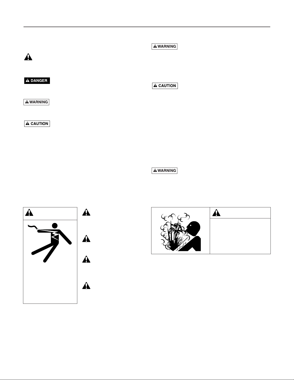
WELL POINT (DRIVEN POINT) INSTALLATION
(Figure 1)
Step 1. Drive the well, using “drive couplings” and a “drive cap”. “Drive
fittings” are threaded all the way through and allow the pipe ends to
butt against each other so that the driving force of the maul is carried by the pipe and
not
by the threads. The ordinary fittings found
in hardware stores are not threaded all the way through the fitting
and can collapse under impact. “Drive fittings” are also smoother
than standard plumbing fittings, making ground penetration easier.
Step 2. Mount the pump as close to the well as possible.
Step 3. Use the fewest possible fittings (especially elbows) when connecting
the pipe from the well point to the pump suction port. The suction
pipe should be at least as large as the suction port on the pump
(include a check valve if your pump is not equipped with one – see
Figure 1). Support the pipe so that there are no dips or sags in the
pipe, so it doesn’t strain the pump body, and so that it slopes slightly upward from the well to the pump (high spots can cause air
pockets which can air lock the pump). Seal the suction pipe joints
with teflon tape or a teflon based pipe joint compound. Joints must
be air- and water-tight.
If the suction pipe can suck air, the pump
cannot pull water from the well.
If one well point does not supply
enough water, consider connecting two or three well points to one
suction pipe.
You have just completed the suction piping for your new shallow
well jet pump. Please go to Page 6 for discharge pipe and tank
connections.
CASED WELL INSTALLATION, 2" OR LARGER
CASING (Figure 2)
Step 1. Mount the pump as close to the well as possible.
Step 2. Assemble the foot valve, strainer, and well pipe (see Figure 2). Make
sure that the foot valve works freely.
Step 3. Lower the pipe into the well until the strainer is five feet above the
bottom of the well. It should also be at least 10 feet below the well’s
water level
while the pump is running
in order to prevent the pump
from sucking air. Install a sanitary well seal.
To Household
Water System
Pump Priming
Tee with Plug
or Gauge
Not
to
Scale
Drive
Coupling
Drive
Point
Priming
Tee and
Plug
Drive point
below water
level
Check
Val ve
Figure 1: Driven Point Installation
Figure 2: Cased Well Installation
To Household
Water System
Pump Priming
Tee with Plug
or Gauge
Suction Pipe
10'
Min.
From Well
Priming
Tee and
Plug
Sanitary
Well Seal
Foot
Valve
Check
Valve
Not
to
Scale
1862 0205 SWJ
5–10'
Page 5
Installation 5
Step 4. Install a priming tee, priming plug, and suction pipe to the pump
(see Figure 2). Connect the pipe from the well to the pump suction
port, using the fewest possible fittings – especially elbows – as fittings increase friction in the pipe (however, include a foot valve –
see Figure 2). The suction pipe should be at least as large as the
suction port on the pump. Use teflon tape or a teflon-based pipe
joint compound on threaded pipe joints. Support the pipe so that
there are no dips or sags in the pipe, so it doesn’t strain the pump
body, and so that it slopes slightly upward from the well to the
pump (high spots can cause air pockets which can air lock the
pump). Seal the suction pipe joints with teflon tape or a teflon
based pipe joint compound. Joints must be air- and water-tight.
If the suction pipe can suck air, the pump cannot pull water from
the well.
You have just completed the suction piping for your new shallow
well jet pump. Please go to Page 6 for discharge pipe and tank
connections.
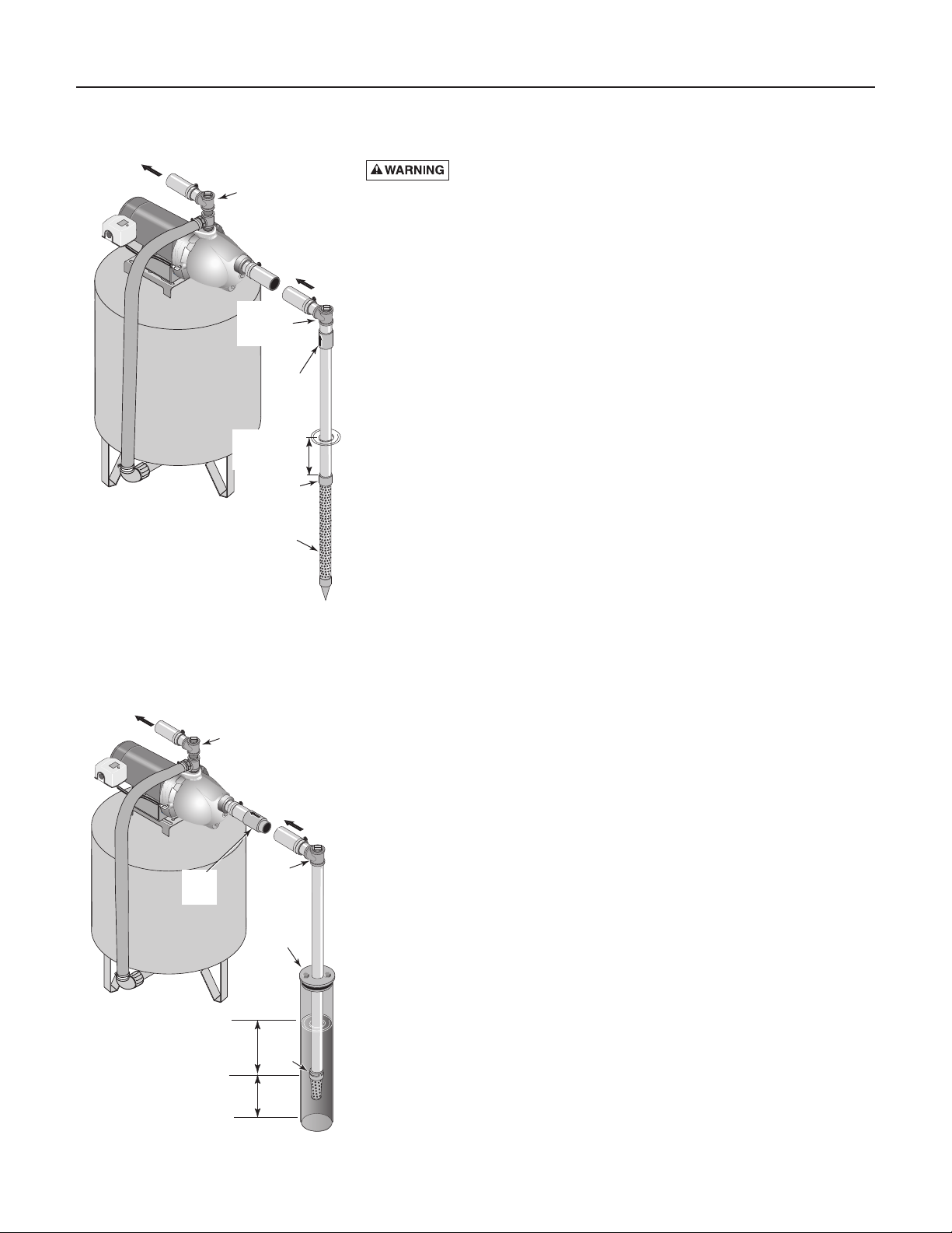
INSTALLATION FOR SURFACE WATER (Figure 3)
Do not use surface water for drinking. The installation shown
could be used for sprinkler applications.
Step 1. The pump should be installed as close to the water as possible,
with the fewest possible fittings (especially elbows) in the suction
pipe. The suction pipe should be at least as large as the suction port
on the pump.
Step 2. Assemble a foot valve and suction pipe (see Figure 3). Make sure
that the foot valve works freely. Use teflon tape or a teflon-based
pipe joint compound on threaded pipe joints. Protect the foot valve
assembly from fish, trash, etc, by installing a screen around it (see
Figure 3).
Step 3. Lower the pipe into the water until the strainer is five feet above the
bottom. It should also be at least 10 feet below the water level in
order to prevent the pump from sucking air.
Step 4. Install a priming tee, priming plug, and suction pipe to the pump
(see Figure 3). Support the pipe so that there are no dips or sags in
the pipe, so it doesn’t strain the pump body, and so that it slopes
slightly upward from the well to the pump (high spots can cause air
pockets which can air lock the pump). Seal the suction pipe joints
with teflon tape or a teflon based pipe joint compound. Joints must
be air- and water-tight.
If the suction pipe can suck air, the pump
cannot pull water from the well.
You have just completed the plumbing for your new shallow well jet
pump. Please go to Page 6 for discharge pipe and tank connections.
Not
to
Scale
Suction Pipe
From Well
10'
Min.
5–10'
Foot
Valve
Screen
To Household
Water System
Pump Priming
Tee with Plug
or Gauge
Figure 3: Surface Water Installation
Page 6
Discharge Pipe and Pressure Tank Connections 6
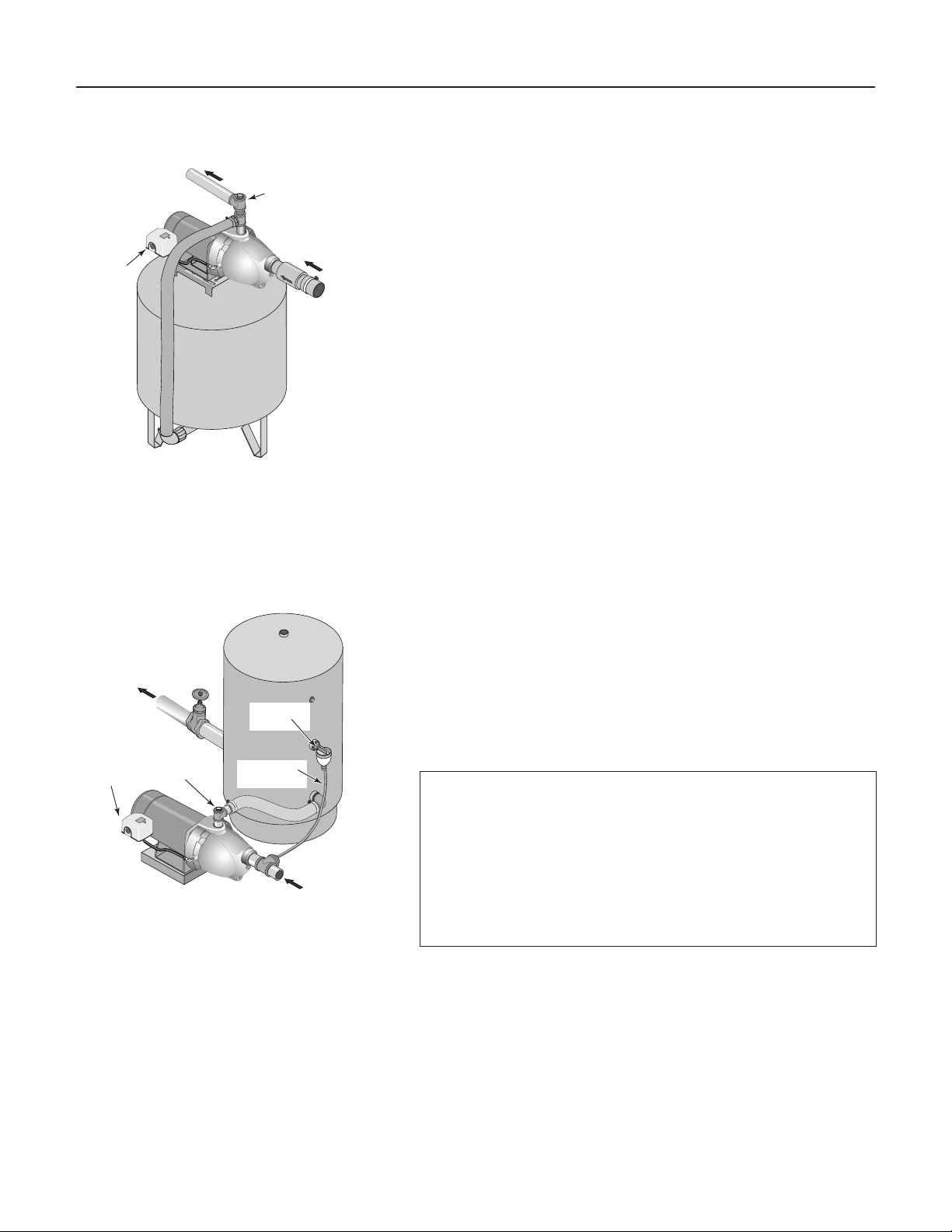
PRE-CHARGE TANK CONNECTION (Figure 4)
Step 1. Install two tees in the pump discharge port (see Figure 4). The pipe
size must be at least as large as the discharge port.
Step 2. Run a pipe or reinforced hose from one arm of the first tee to the
port on the pre-charged tank.
Step 3. Connect the other end of the discharge tee to your plumbing system.
Cap the tee with a threaded plug or a pressure gauge.
Step 4. Check the pre-charge of air in the tank with an ordinary tire gauge.
The pre-charge should be 2 PSI less than the cut-in setting of the
pump’s pressure switch. The pre-charge is measured
when there is
no water pressure in the tank.
Your new pump has a 30/50 PSI
switch, so adjust the tank pre-charge pressure to 28 PSI.
Congratulations! You have just completed the tank connection for
your jet pump.
Please go to Page 7 for electrical hookup.
STANDARD TANK CONNECTION (Figure 5)
Step 1. Install one tee in the pump discharge port (see Figure 5).
Step 2. Run a pipe from the pump discharge port to the inlet port of your
tank. The pipe size must be at least as large as the discharge port.
Step 3. Install a tee in the suction pipe near the pump. Install a reducer
bushing down to 1/8” NPT in the tee. Run tubing from the tee to
the port on the AVC mounted on the tank. Seal all joints with teflon
tape. See instructions provided with the tank and the AVC for
details.
Congratulations! You have just completed the tank connection for
your jet pump.
Please go to Page 7 for electrical hookup.
From
Well
To Household
Water System
Pump Priming
Tee with Plug
or Gauge
Pressure
Switch
Figure 4: Pre-charged Tank Connections
Figure 5: Standard Tank Connections
Sealing Pipe Joints
Use only Teflon tape or Teflon based joint compounds for
making all threaded connections to the pump itself. Do not use
pipe joint compounds on plastic pumps: they can react with
the plastic in pump components. Make sure that all pipe joints
in the suction pipe are air tight as well as water tight.
If the
suction pipe can suck air, the pump will not be able to pull
water from the well.
To Household
Water System
Air Volume
Control
Pump Priming
Pressure
Switch
Tee and Plug
or Gauge
Air Volume
Control Tube
From
Well
Page 7
Electrical 7
Disconnect power before working on pump, motor, pressure switch, or wiring.
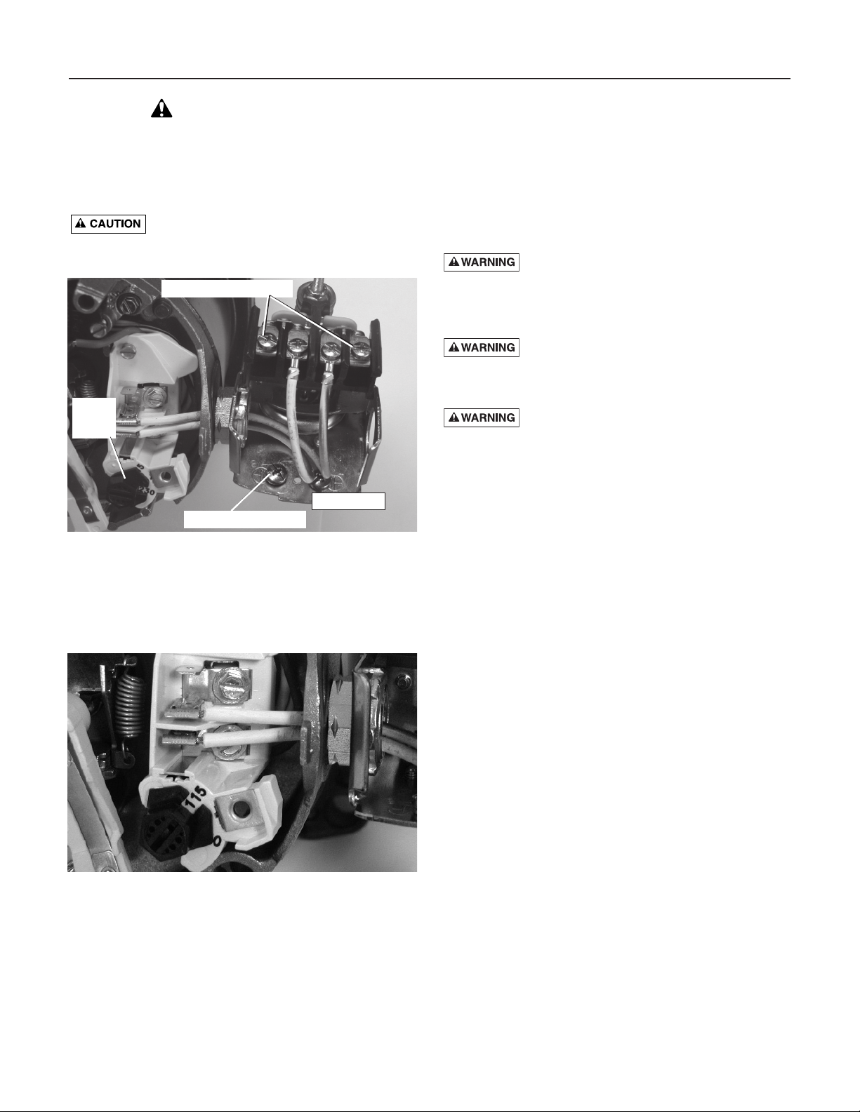
Dial Type Voltage Selector
Voltage is factory set to 230 volts. To change to 115 volts:
1. Make sure power is off.
2. Turn the dial counter-clockwise until 115 shows in the
dial window as shown in Figure 7.
3. Attach the incoming power leads to the two outer
screws on the pressure switch as shown in Figure 6.
4. Attach the ground wire to the grounding connections
as shown in Figure 6.
5. If there are other wires, they should be capped.
6. Reinstall the Motor end cover.
Hazardous voltage. Can shock, burn, or kill.
Connect ground wire before connecting power supply
wires. Use the wire size (including the ground wire) specified in the wiring chart. If possible, connect the pump to a
separate branch circuit with no other appliances on it.
Explosion hazard. Do not ground to a gas
supply line.
WIRING CONNECTIONS
Fire hazard. Incorrect voltage can cause a
fire or seriously damage the motor and voids the warranty. The supply voltage must be within ±10% of the motor
nameplate voltage.
NOTICE: Dual-voltage motors are factory wired for 230
volts. If necessary, reconnect the motor for 115 volts, as
shown. Do not alter the wiring in single voltage motors.
Install, ground, wire, and maintain your pump in compliance with the National Electrical Code (NEC) or the
Canadian Electrical Code (CEC), as applicable, and with
all local codes and ordinances that apply. Consult your
local building inspector for code information.
Connection Procedure:
Step 1. Connect the ground wire first as shown in Figure
6. The ground wire must be a solid copper wire
at least as large as the power supply wires.
Step 2. There must be a solid metal connection between
the pressure switch and the motor for motor
grounding protection. If the pressure switch is not
connected to the motor, connect the green
ground screw in the switch to the green ground
screw under the motor end cover. Use a solid
copper wire at least as large as the power supply
wires.
Step 3. Connect the ground wire to a grounded lead in a
service panel, to a metal underground water
pipe, to a metal well casing at least ten feet (3M)
long, or to a ground electrode provided by the
power company or the hydro authority.
Step 4. Connect the power supply wires to the pressure
switch as shown in Figure 6.
You have just completed the wiring for your pump.
Please go to Page 8 for startup preparations.
NOTE: 1/2 HP motors are wired for 115 volts only, and have no motor wiring to change.
3/4 HP or 1 HP motor terminal boards (located under the motor end cover) should look like one of those below.
If the motor can operate at either 115 or 230 volts, it is set at the factory to 230 volts. Do not change motor wiring
if line voltage is 230 volts, or if you have a single voltage motor.
Never wire a 115 volt motor to a 230 volt line.
MOTOR SWITCH SETTINGS
Figure 6:Voltage set to 230 volts, Dial Type
Ground Wire Connection
Power Supply Connections
Voltage
Change
Dial
Pressure Switch
Figure 7:Voltage set to 115 volts, Dial Type
Page 8
Preparing to Start the Pump
Follow winterizing
instructions.
Pump and piping will be
damaged if frozen and
not drained.
Electrical 8
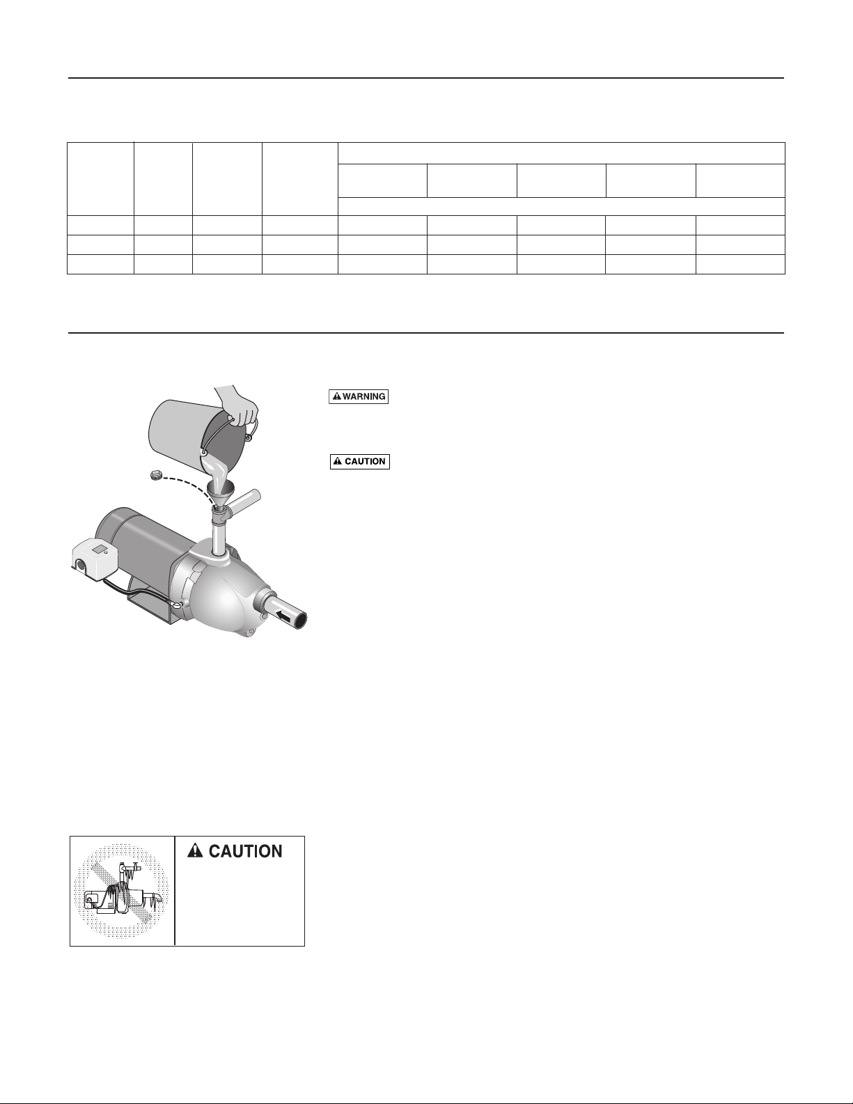
PRIMING
Never run pump against closed discharge. To do so can boil
water inside pump, causing hazardous pressure in unit, risk of explosion
and possibly scalding persons handling pump.
Never run pump dry. Running pump without water may cause
pump to overheat, damaging seal and possibly causing burns to persons
handling pump. Fill pump with water before starting.
Step 1. Remove the priming plug from the pump and fill the pump, fill all pip-
ing between the pump and the well, and make sure that all piping in
the well is full. If you have also installed a priming tee in the suction
piping, remove the plug from the tee and fill the suction piping.
Step 2. Replace all fill plugs.
Step 3. Power on! Start the pump. If you don’t have water after 2 or 3 min-
utes, stop the pump and remove the fill plugs. Refill the pump and
piping. You may have to repeat this several times in order to get all
the trapped air out of the piping. A pump lifting water 25’ may take
as long as 15 minutes to prime.
Step 4. After the pump has built up pressure in the system and shut off,
check the pressure switch operation by opening a faucet or two and
running enough water out to bleed off pressure until the pump
starts. The pump should start when pressure drops to 30 PSI and
stop when pressure reaches 50 PSI. Run the pump through one or
two complete cycles to verify correct operation. This will also help
clean the system of dirt and scale dislodged during installation.
WINTERIZING THE PUMP
To prepare the pump for freezing temperatures:
Step 1. Shut off power to the pump.
Step 2. Relieve system pressure. Open a faucet and let it drain until water
stops flowing.
Step 3. Drain the pump. Your pump may have a separate drain plug.
Remove this plug and let it drain.
Your pump may only have a plug or connection on the side of the
pump. Remove this and let the pump drain. Some water will
remain in the pump. A small amount of water left in the pump will
not harm it if it freezes.
DISTANCE IN FEET(METERS) FROM MOTOR TO SUPPLY
0 - 100 101 - 200 201 - 300 301 - 400 401 - 500
Max. Load Branch Fuse
(0 - 30) (31 - 61) (62 - 91) (92 - 122) (123 - 152)
Motor HP Volts Amp Rating Amp AWG WIRE SIZE (mm2)
1/2 115/230 9.9/4.95 15/15 14/14 (2/2) 10/14 (5.5/2) 10/14 (5.5/2) 6/14 (14/2) 6/12 (14/3)
3/4 115/230 12.4/6.2 20/15 12/14 (3/2) 10/14 (5.5/2) 8/14 (8.4/2) 6/12 (14/3) 6/12 (14/3)
1 115/230 14.8/7.4 20/15 12/14 (3/2) 8/14 (8.4/2) 6/14 (14/2) 6/12 (4/3) 4/10 (21/5.5)
Wiring Chart – Recommended Wire and Fuse Sizes
Figure 8: Prime the Pump
Page 9
Repair Parts 9
1
2
3
4
5
5A
6
7
8
9
10
11
12
13
14
15
4793 0105
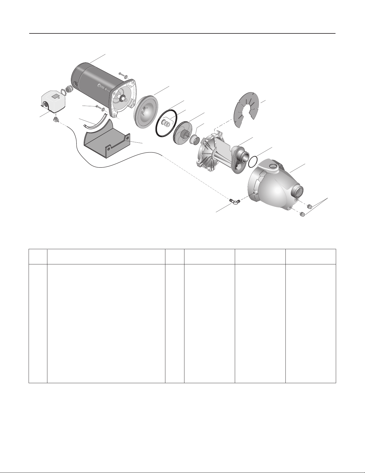
Ref. PNC PND PNE
No. Description Qty. 1/2 HP 3/4 HP 1 HP
1 Motor 1 J218-582APKG J218-590PKG J218-596PKG
2 Seal Plate 1 N3-15P N3-15P N3-15P
3 O-Ring 1 U9-390 U9-390 U9-390
4 Shaft Seal 1 U109-6A U109-6A U109-6A
5 Impeller 1 J105-40PNB J105-42PNB J105-22PB
5A Floating Wear Ring 1 N23-12SS N23-12SS N23-11SS
6 Priming Baffle 1 U97-153P U97-153P U97-153P
7 Nozzle / Venturi / Diffuser Assembly 1 N101-30PA N101-30P N101-29P
8 Nozzle O-Ring 1 U9-449 U9-449 U9-449
9 Pump Body 1 N76-46P N76-46P N76-46P
10 1/4" Plug 2 § § §
11 Barbed Fitting 2 U111-212T U111-212T U111-212T
12 Base 1 J104-9F J104-9F J104-9F
13 Rubber Pad 1 C35-5 C35-5 C35-5
14 3/8" x 2" Capcrews 4 § § §
15 Pressure Switch 1 U217-1202 U217-1202 U217-1202
§ Common hardware, purchase locally.
Repair Parts
Page 10

Troubleshooting 10
* (Note:
Stop pump;
then check prime
before looking for
other causes.
Unscrew
priming
plug and see if water
is in priming hole).
SYMPTOM POSSIBLE CAUSE(S) CORRECTIVE ACTION
Motor will not run Disconnect switch is off Be sure switch is on.
Fuse is blown or circuit breaker tripped Replace fuse or reset circuit breaker.
Starting switch is defective DISCONNECT POWER; Replace starting switch.
Wires at motor are loose, Refer to instructions on wiring (Page 7). DISCONNECT POWER; check and
disconnected, or wired incorrectly tighten all wiring.
Capacitor voltage may be hazardous. To discharge
capacitor, hold insulated handle screwdriver BY THE HANDLE and
short capacitor terminals together. Do not touch metal screwdriver
blade or capacitor terminals. If in doubt, consult a qualified electrician.
Pressure switch contacts are dirty DISCONNECT POWER and file contacts with emery board or nail file.
Motor runs hot and Motor is wired incorrectly Refer to instructions on wiring.
overload kicks off
Voltage is too low Check with power company. Install heavier wiring if wire size is too small
(See Electrical / Wiring Chart).
Pump cycles too frequently See section below on too frequent cycling.
Motor runs but no Pump in new installation did In new installation:
water is delivered* not pick up prime through:
1. Improper priming 1. Re-prime according to instructions.
2. Air leaks 2. Check all connections on suction line, AVC, and ejector with
soapy water or shaving cream.
3. Leaking foot valve or check valve 3. Replace foot valve or check valve.
Pump has lost prime through: In installation already in use:
1. Air leaks 1. Check all connections on suction line and shaft seal.
2. Water level below suction pipe inlet 2. Lower suction line into water and re-prime. If receding water level
in well exceeds 25’ (7.6M), a deep well pump is needed.
Foot valve or strainer is plugged Clean foot valve or strainer.
Ejector or impeller is plugged Clean ejector or impeller.
Check valve or foot valve is stuck shut Replace check valve or foot valve.
Pipes are frozen Thaw pipes. Bury pipes below frost line. Heat pit or pump house.
Foot valve and/or strainer are Raise foot valve and/or strainer above bottom of water source.
buried in sand or mud Clean foot valve and strainer.
Water level is too low for shallow well A deep well jet package may be needed (over 25 ft. to water)
setup to deliver water to deliver water.
Pump does not Water level in well is lower than A deep well jet will be needed if your well is more than 25’ (7.6M)
deliver water to full estimated depth to water.
capacity
Steel piping (if used) is corroded or Replace with plastic pipe where possible, otherwise with new steel pipe.
limed, causing excess friction
Piping is too small in size Use larger piping.
Packed well point Backflush well point or sink new point.
Pump delivers water but
Pressure switch is out of adjustment or DISCONNECT POWER; adjust or replace pressure switch.
does not shut off or contacts are welded together
pump cycles too
Faucets have been left open Close faucets.
frequently
Venturi, nozzle or impeller is clogged Clean venturi, nozzle or impeller.
Standard pressure tank is waterlogged Drain tank to air volume control port. Check AVC for defects. Check
and has no air cushion all connections for air leaks.
Pipes leak Check connections.
Foot valves leak Replace foot valve.
Air charge too low in pre-charged tank DISCONNECT POWER and open faucets until all pressure is relieved.
Using tire pressure gauge, check air pressure in tank at valve stem
located on the tank. If less than pressure switch cut-in setting (30-50
PSI), pump air into tank from outside source until air pressure is 2 PSI
less than cut-in setting of switch. Check air valve for leaks (use soapy
solution) and replace core if necessary.
Air spurts from faucets Pump is picking up prime When pump has picked up prime, it should pump solid water with no air.
Leak in suction side of pump Suction pipe is sucking air. Check joints for leaks with soapy water.
Well is gaseous Consult factory about installing a sleeve in the well
Intermittent over-pumping of well. Lower foot valve if possible, otherwise restrict pump discharge
(Water drawn down below foot valve.)
Page 11

Sécurité 11
LIRE TOUTES CES INSTRUCTIONS
ET LES SUIVRE!
Ce symbole indique qu'il faut être prudent.
Lorsque ce symbole apparaît sur la pompe ou dans
cette Notice, rechercher une des mises en garde qui
suivent, car elles indiquent un potentiel possible de
blessures corporelles :
avertit d'un danger qui causera des blessures
corporelles, la mort ou des dommages matériels importants
si on l'ignore.
avertit d'un danger qui risque de causer
des blessures corporelles, la mort ou des dommages
matériels importants si on l'ignore.
avertit d'un danger qui causera ou qui
risquera de causer des blessures corporelles, la mort ou des
dommages matériels importants si on l'ignore.
Le mot NOTA indique des instructions spéciales et impor-
tantes n'ayant aucun rapport avec les dangers.
Lire attentivement toutes les consignes de sécurité
contenues dans cette Notice ou collées sur la pompe.
Garder les autocollants de sécurité en bon état; les
remplacer s'ils manquent ou s'ils ont été endommagés.
SÉCURITÉ CONCERNANT L'ÉLECTRICITÉ
La tension du condensateur peut être dan-
gereuse. Pour décharger le condensateur du moteur, tenir
un tournevis à manche isolé PAR LE MANCHE et mettre en
court-circuit les bornes du condensateur. Ne pas toucher la
lame métallique du tournevis ni les bornes du condensateur.
En cas de doute, consulter un électricien qualifié.
SÉCURITÉ GÉNÉRALE
Ne pas toucher un moteur qui fonctionne.
Les moteurs peuvent fonctionner par les températures
élevées. Pour ne pas se brûler lorsque l'on interviendra sur
la pompe, la laisser refroidir pendant 20 minutes après
l'avoir arrêtée avant de la toucher.
Ne pas laisser geler la pompe ni aucun autre élément du
système, sinon la garantie sera annulée.
Ne pomper que de l'eau avec cette pompe.
Périodiquement, inspecter la pompe et tous les éléments du
système.
Toujours porter des lunettes de sécurité lorsque l'on inter-
vient sur une pompe.
Garder la zone de travail propre, non encombrée et bien
éclairée; tous les outils et tout l'équipement non utilisés
doivent être entreposés correctement.
Ne pas laisser les visiteurs s'approcher de la zone de travail.
Le corps de la pompe peut exploser si la
pompe est utilisée en tant que pompe de surpression, à
moins qu'une soupape de sûreté pouvant laisser passer le
débit maximum de la pompe à 75 lb/po
2
soit posée.
AVERTISSEMENT
Pression dangereuse!
Poser une soupape de sûreté
sur le tuyau de refoulement.
Dissiper toute la pression
du système avant d'intervenir
sur un élément.
AVERTISSEMENT
Tension dangereuse. Risque
de secousses électriques, de
brûlures, voire de mort.
Mettre à la terre la pompe
avant de la brancher sur le
courant électrique. Couper
l'arrivée de courant avant d'intervenir sur la pompe, sur le
moteur ou sur le réservoir.
Câbler le moteur en
fonction de la bonne
tension. Voir la Section
«Électricité» de cette Notice
et la plaque signalétique du
moteur.
Mettre à la terre le
moteur avant de le
brancher sur le courant
électrique.
Conforme au Code
national de l'électricité, au Code canadien de
l'électricité et aux codes
municipaux pour tous les
câblages.
Respecter les instructions de câblage figurant dans
cette Notice lorsque l'on branche le moteur sur
une ligne haute tension.
Page 12

Table des matières 12
Merci d'avoir acheté une pompe de qualité supérieure mise à l'essai à l'usine.
Page
Sécurité ..........................................................................................................................11
Garantie .........................................................................................................................12
Installation.................................................................................................................13,14
Branchement de la tuyauterie de refoulement ................................................................15
Électricité...................................................................................................................16,17
Préparations avant le démarrage de la pompe................................................................17
Pièces de rechange.........................................................................................................18
Diagnostic des pannes....................................................................................................19
GARANTIE LIMITÉE
STA-RITE garantit au consommateur initial (ci-après appelé l’« Acheteur ») que les produits énumérés dans les présentes sont
exempts de défaut de matériau et de fabrication pendant la durée des garanties à compter de la durée des garanties indiquées
ci-dessous.
Produits Durée des garanties
Produits de systèmes d’eau —
Selon le premier terme atteint
:
Pompes à éjecteur, petites pompes 12 mois à compter de la date de la première installation ou
centrifuges, pompes submersibles et 18 mois à compter de la date de fabrication
tous les accessoires connexes
Réservoirs composites Pro-Source
TM
5 ans à compter de la date de la première installation
Réservoirs sous pression en acier Pro-Source
TM
5 ans à compter de la date de la première installation
Réservoirs revêtus d’époxyde Pro-Source
TM
3 ans à compter de la date de la première installation
Produits de puisard/d’égout/d’effluents 12 mois à compter de la date de la première installation ou
18 mois à compter de la date de fabrication
Nos garanties ne s’appliquent pas aux produits ayant fait l’objet de négligence, d’une mauvaise utilisation, d’une mauvaise
installation ou d’un manque d’entretien adéquat. Sans aucune limitation des présentes, la garantie des moteurs triphasés
submersibles sera nulle et non avenue si ces moteurs sont branchés et fonctionnent sur le courant monophasé par
l’intermédiaire d’un déphaseur. Il faut également noter que les moteurs triphasés doivent être protégés par un relais de
surcharge tripolaire thermocompensé à déclenchement extrêmement rapide du calibre recommandé, sinon la garantie sera nulle
et non avenue.
Le seul recours de l’Acheteur et la seule responsabilité de STA-RITE consistent à réparer ou à remplacer (au choix de STA-RITE)
les produits qui se révéleraient défectueux. L’Acheteur s’engage à payer tous les frais de main-d’œvre et d’expédition du produit
couvert par sa garantie et de s’adresser au concessionnaire-installateur ayant procédé à l’installation dès qu’un problème est
découvert pour obtenir un service sous garantie. Aucune demande de service en vertu de sa garantie ne sera acceptée après
expiration de la durée de sa garantie. Ces garanties ne sont pas transférables.
STA-RITE DÉCLINE TOUTE RESPONSABILITÉ POUR TOUT DOMMAGE INDIRECT OU FORTUIT QUEL QU’IL SOIT.
LES PRÉSENTES GARANTIES SONT EXCLUSIVES ET TIENNENT LIEU DE TOUTE AUTRE GARANTIE FORMELLE
ET TACITE, Y COMPRIS, MAIS SANS S’Y LIMITER, TOUTE GARANTIE TACITE DE QUALITÉ MARCHANDE OU DE
CONVENANCE DU PRODUIT À UNE FIN PARTICULIÈRE. LA DURÉE DES PRÉSENTES GARANTIES NE DEVRA PAS
DÉPASSER LA DURÉE DES GARANTIES FORMELLES STIPULÉES DANS LES PRÉSENTES.
Certains états, territoires et certaines provinces ne permettent pas l’exclusion ou la limitation des dommages indirects ou fortuits,
ni les limitations relatives à la durée des garanties tacites. Par conséquent, il se peut que les limitations ou les exclusions
stipulées dans les présentes ne s’appliquent pas dans ce cas. Ces garanties accordent des droits juridiques précis, bien que l’on
puisse bénéficier d’autres droits, selon la province, le territoire ou l’état dans lequel on réside.
Ces garanties remplacent et annulent toutes les garanties précédemment publiées.
STA-RITE INDUSTRIES
293 Wright St., Delavan,WI 53115
Page 13

Installation 13
REMPLACEMENT D'UNE ANCIENNE POMPE
Tension dangereuse. Couper l'arrivée de courant à la pompe
avant d'intervenir sur la pompe ou sur le moteur.
1 ° Vider toute l'eau de l'ancienne pompe; déposer l'ancienne pompe. Vérifier
l'ancienne tuyauterie à la recherche de dépôts de tartre, de chaux, de
rouille, etc.; la remplacer selon le besoin.
2 ° Brancher la pompe sur le système. S'assurer que tous les raccords du tuyau
d'aspiration sont bien étanches, aussi bien à l'air qu'à l'eau.
Si le tuyau
d'aspiration aspire de l'air, la pompe ne pompera pas l'eau du puits.
3 ° Régler la hauteur de montage de la pompe de façon que les raccords de
plomberie n'exercent aucune contrainte sur le corps de la pompe.
Supporter les tuyaux de façon que le corps de la pompe ne supporte pas le
poids de la tuyauterie ni des raccords.
Le branchement de cette pompe à éjecteur neuve pour puits profonds sur la
tuyauterie du puits est maintenant terminé. Passer à la page 15 pour le
branchement de la tuyauterie de refoulement et sur un réservoir.
INSTALLATION DE LA POINTE FILTRANTE (Figure 1)
1 ° Enfoncer la pointe dans le sol, en utilisant des «raccords d'enfoncement» et
des «chapeaux de battage». Les «raccords d'enfoncement» sont filetés sur
toute leur longueur, ce qui permet aux extrémités des tuyaux de venir en
butée l'une contre l'autre de façon que la force d'enfoncement du maillet
soit absorbée par le tuyau et non
pas
par les filets. Les raccords ordinaires
que l'on trouve dans les quincailleries ne sont pas filetés sur toute leur
longueur et ils risquent de s'écraser sous l'impact des coups. Les «raccords
d'enfoncement» sont également plus lisses que les raccords de plomberie
standard, ce qui leur permet de pénétrer plus facilement dans le sol.
2 ° Monter la pompe aussi près que possible du puits.
3 ° Utiliser le moins possible de raccords (en particulier des coudes) lorsque
l'on branche la tuyauterie de la pointe filtrante sur l'orifice d'aspiration de
la pompe. Le diamètre du tuyau d'aspiration doit être au moins aussi grand
que le diamètre de l'orifice d'aspiration de la pompe (y compris le clapet
anti-retour si la pompe n'en comporte pas un - voir la Figure 1). Supporter
le tuyau de façon qu'il ne soit pas cintré afin qu'il n'exerce pas de contraintes sur le corps de la pompe; de plus, il doit être légèrement incliné
vers le haut, du puits jusqu'à la pompe (les points hauts risquent de causer
des poches et des bouchons d'air dans la pompe). Rendre étanches les raccords du tuyau d'aspiration avec du ruban téflon ou une pâte pour raccords
filetés à base de téflon. Les raccords doivent être étanches à l'air et à l'eau.
Si le tuyau d'aspiration aspire de l'air, la pompe ne pompera pas l'eau du
puits.
Si une pointe filtrante ne fournit pas suffisamment d'eau, considérer
brancher deux ou trois pointes filtrantes sur un même tuyau d'aspiration.
Le branchement de cette pompe à éjecteur neuve pour puits profonds sur la
tuyauterie du puits est maintenant terminé. Passer à la page 15 branchement
pour la tuyauterie de refoulement et sur un réservoir.
INSTALLATION SUR UN PUITS À TUBAGE DE 2
POUCES DE DIAMÈTRE OU PLUS GRAND
(voir la Figure 2)
1 ° Monter la pompe aussi près que possible du puits.
2 ° Brancher le clapet de pied, la crépine et le tuyau du puits (voir la Figure 2).
S'assurer que le clapet de pied fonctionne librement.
3 ° Abaisser le tuyau dans le puits jusqu'à ce que la crépine soit à cinq pieds
du fond du puits. Pour que la pompe n'aspire pas d'air, la crépine doit être
au moins à 10 pieds sous le niveau de l'eau du puits
pendant que la
pompe fonctionne.
Poser un joint sanitaire de puits.
Figure 1: Installation avec une pointe
filtrante
Figure 2 : Installation dans un puits à
tubage
Vers le système d'eau
de la maison
Pas à
l'échelle
Pointe
filtrante
Clapet
anti-retour
Pointe filtrante
sous le niveau
de l’eau.
Té
d'amorçage
et bouchon
Té d’amorçage de la
pompe avec bouchon
ou manomètre
Tuyau d'aspiration
venant du puits
Joint sanitaire
du puits
Clapet
de pied
Au moins
10 pi
5 à 10 pi
Té d’amorçage de la
pompe avec bouchon
ou manomètre
Raccord d'enfoncement
de la pointe filtrante
Pas à
l'échelle
Vers le système
d'eau de la maison
Clapet
anti-retour
Tuyau d'aspiration
venant du puits
T H h l
1862 0205 SWJ
Page 14

Installation 14
4 ° Poser le té d'amorçage, le bouchon d'amorçage et le tuyau d'aspiration sur
la pompe (voir la Figure 2). Brancher le tuyau provenant du puits sur l'orifice d'aspiration de la pompe en utilisant le moins possible de raccords en particulier des coudes - étant donné que les raccords augmentent le
frottement de l'eau dans les tuyaux (il faut toutefois ajouter un clapet de
pied — voir la Figure 2). Le diamètre du tuyau d'aspiration doit être au
moins aussi grand que le diamètre de l'orifice d'aspiration de la pompe.
Utiliser du ruban téflon ou de la pâte pour raccords filetés à base du téflon
sur les raccords filetés. Supporter le tuyau de façon qu'il ne soit pas cintré
afin qu'il n'exerce pas de contraintes sur le corps de la pompe; de plus, il
doit être légèrement incliné vers le haut, du puits jusqu'à la pompe (les
points hauts risquent de causer des poches et des bouchons d'air dans la
pompe). Rendre étanches les raccords du tuyau d'aspiration avec du ruban
téflon ou une pâte pour raccords filetés à base de téflon. Les raccords
doivent être étanches à l'air et à l'eau.
Si le tuyau d'aspiration aspire de
l'air, la pompe ne pompera pas l'eau du puits.
Le branchement de cette pompe à éjecteur neuve pour puits profonds sur la
tuyauterie du puits est maintenant terminé. Passer à la page 15 pour le
branchement de la tuyauterie de refoulement et sur un réservoir.
INSTALLATION DANS LE CAS D'EAUX EN SURFACE
(Figure 3)
Ne pas boire l’eau de surface. L’installation montrée peut être
utilisée pour l’arrosage.
1 ° Monter la pompe aussi près que possible du puits en utilisant le moins
possible de raccords (en particulier des coudes) sur le tuyau d'aspiration.
Le diamètre du tuyau d'aspiration doit être au moins aussi grand que le
diamètre de l'orifice d'aspiration de la pompe.
2 ° Assembler le clapet de pied et le tuyau d'aspiration (voir la Figure 3).
S'assurer que le clapet de pied fonctionne librement. Utiliser du ruban
téflon ou de la pâte pour raccords filetés à base de téflon sur les raccords
filetés. Poser une crépine autour du clapet de pied pour le protéger contre
les poissons, les déchets, etc. (voir la Figure 3).
3 ° Abaisser le tuyau dans le puits jusqu'à ce que la crépine soit à cinq pieds
du fond du puits. Pour que la pompe n'aspire pas d'air, la crépine doit être
au moins à 10 pieds sous le niveau de l'eau du puits pendant que la
pompe fonctionne.
4 ° Poser le té d'amorçage, le bouchon d'amorçage et le tuyau d'aspiration sur
la pompe (voir la Figure 3). Supporter le tuyau de façon qu'il ne soit pas
cintré afin qu'il n'exerce pas de contraintes sur le corps de la pompe; de
plus, il doit être légèrement incliné vers le haut, du puits jusqu'à la pompe
(les points hauts risquent de causer des poches et des bouchons d'air dans
la pompe). Rendre étanches les raccords du tuyau d'aspiration avec du
ruban téflon ou une pâte pour raccords filetés à base de téflon. Les raccords doivent être étanches à l'air et à l'eau.
Si le tuyau d'aspiration aspire
de l'air, la pompe ne pompera pas l'eau du puits.
Le branchement de cette pompe à éjecteur neuve pour puits profonds sur la
tuyauterie du puits est maintenant terminé. Passer à la page 15 pour le
branchement de la tuyauterie de refoulement et sur un réservoir.
Figure 3 : Installation pour les eaux de
surface
Pas à
l'échelle
Au moins
10 pied
5 à 10 pi
Crépine
Clapet
de
pied
Tuyau d'aspiration
venant du puits
Té d’amorçage de la
pompe avec bouchon
ou manomètre
Vers le système
d'eau de la maison
Page 15

Branchement de la tuyauterie de refoulement
et sur un réservoir sous pression 15
BRANCHEMENT SUR UN RÉSERVOIR PRÉCHARGÉ
(Figure 4)
1 ° Poser deux tés dans l'orifice de refoulement de la pompe (voir la Figure 4).
Le diamètre du tuyau doit être au moins aussi grand que le diamètre de
l'orifice de refoulement.
2 ° Poser un tuyau rigide ou un tuyau souple renforcé entre une des branches
du premier té et l'orifice du réservoir préchargé.
3 ° Brancher l'autre extrémité du té de refoulement sur le système de la
plomberie. Boucher le té avec un bouchon fileté ou un manomètre.
4 ° Vérifier la précharge d'air dans le réservoir avec un manomètre pour pneu.
La précharge doit être de 2 lb/po
2
inférieure au réglage de la pression d'enclenchement du manocontacteur de la pompe. La précharge se mesure
lorsqu'il n'y a pas de pression d'eau dans le réservoir. Cette pompe neuve
est équipée d'un manocontacteur 30/50 lb/po
2
; la pression de précharge
du réservoir devra donc être réglée à 28 lb/po
2
.
Félicitations! Le branchement de la pompe à éjecteur sur le réservoir est
maintenant terminé.
Passer à la page 16 pour les branchements électriques.
BRANCHEMENT SUR UN RÉSERVOIR STANDARD
(Figure 5)
1 ° Poser un té dans l'orifice de refoulement de la pompe (voir la Figure 5).
2 ° Poser un tuyau entre l'orifice de refoulement de la pompe et l'orifice d'ad-
mission du réservoir. Le diamètre du tuyau doit être au moins aussi grand
que le diamètre de l'orifice de refoulement de la pompe.
3 ° Poser un té dans le tuyau d’aspiration près de la pompe. Poser une bague
de réduction jusqu’à 1/8 po NPT dans le té. Poser un tube entre le té et
l’orifice du contrôleur d’air monté sur le réservoir. Sceller tous les joints
avec du ruban téflon. Se reporter aux instructions fournies avec le réservoir
et le contrôleur d’air pour plus de détails.
Félicitations! Le branchement de la pompe à éjecteur sur le réservoir est
maintenant terminé.
Passer à la page 16 pour les branchements électriques.
P
Figure 4 : Branchements sur un
réservoir préchargé
Figure 5 : Branchements sur un réservoir
standard
Vers le système
d'eau de la maison
Té d’amorçage de la
pompe avec bouchon
ou manomètre
Manocontacteur
En provenance
du puits
Contrôleur
d'air
Tube du
contrôleur d'air
En provenance
du puits
Manocontacteur
Té d’amorçage de la
pompe avec bouchon
ou manomètre
Vers le système
d'eau de la maison
Étanchéité des raccords des tuyaux
N'utiliser que du ruban téflon ou de la pâte d'étanchéité pour
raccords filetés à base de téflon pour procéder à tous les raccords filetés sur la pompe. Ne pas utiliser de pâte pour rac-
cords filetés sur les pompes en plastique : cette pâte peut réagir avec les éléments en plastiques de la pompe. S'assurer que
tous les raccords du tuyau d'aspiration sont bien étanches,
aussi bien à l'air qu'à l'eau.
Si le tuyau d'aspiration aspire de
l'air, la pompe ne pompera pas l'eau du puits.
Page 16

Électricité 16
Débrancher le courant électrique avant d'intervenir sur la pompe, le moteur, le manostat ou le câblage.
Sélecteur de tension à cadran
La tension est réglée en usine à 230 volts. Pour passer au
courant de 115 volts :
1. S’assurer que le courant est coupé.
2. Tourner le cadran dans le sens des aiguilles d’une montre
jusqu’à ce que le nombre 115 soit visible dans la fente
du cadran (figure 7).
3. Fixer les fils d’arrivée de courant aux deux vis extérieures
du manostat (figure 6).
4. Relier le fil de terre aux bornes de raccord de mise à la
terre (figure 6).
5. S’il y a d’autres fils, leurs bouts doivent être isolés.
6. Reposer le couvercle d’extrémité du moteur.
Tension dangereuse. Risque de secousses électriques, de brûlures, voire la mort. Brancher le fil de terre avant
de brancher les fils de tension. Utiliser des fils de calibre spécifié
(y compris le fil de terre) dans le tableau de câblage. Dans la
mesure du possible, brancher la pompe sur un circuit séparé, sur
lequel aucun autre appareil ne sera branché.
Risque d'explosion. Ne pas mettre à la terre
sur une conduite de gaz.
CONNEXIONS DES FILS
Risque d'incendie. L'utilisation d'une mau-
vaise tension risque de causer un incendie ou d'endommager
gravement le moteur et d'annuler la garantie. La tension d'alimentation doit correspondre à ± 10 % de la tension figurant sur
la plaque signalétique du moteur.
NOTA : Les moteurs bi-tension sont câblés à l'usine pour fonctionner sur le 230 volts. Au besoin, recâbler le moteur pour
qu'il fonctionne sur le 115 volts, comme il est illustré. Ne pas
modifier le câblage des moteurs fonctionnant sur une tension.
Installer la pompe, la mettre à la terre, la câbler et l'entretenir
conformément au National Electrical Code (NEC) ou au Code
canadien de l'électricité, selon le cas, et conformément à tous
les codes et décrets en vigueur de la municipalité. Consulter
l'inspecteur des bâtiments de la localité pour plus de renseignements sur les codes.
Méthodes de connexion :
1 ° Brancher tout d'abord le fil de mise à la terre, comme il
est illustré à la Figure 6. Le fil de mise à la terre doit
être un fil de cuivre massif d'un diamètre au moins
aussi gros que le diamètre des fils de tension.
2 ° Il doit y avoir un raccordement en métal solide entre le
manostat et le moteur pour une protection à la terre du
moteur. Si le manostat n'est pas branché sur le moteur,
brancher la vis verte de mise à la terre du manostat sur la
vis verte de mise à la terre qui se trouve sous le couvercle
du moteur. Utiliser un fil de cuivre massif ayant un
diamètre au moins aussi gros que celui des fils de tension.
3 ° Brancher le fil de mise à la terre sur le fil de mise à la
terre du tableau de distribution, sur un tuyau métallique
d'eau enterré, sur le tubage d'un puits en métal ayant
au moins 10 pieds (3 mètres) de long, ou sur une électrode de mise à la terre que fournira la compagnie
d'électricité.
4 ° Brancher les fils de tension sur le manostat, comme il
est illustré à la Figure 6.
Le câblage de la pompe est maintenant terminé.
Se reporter à la page 17 pour les préparations avant le
démarrage.
REMARQUE : Les moteurs de 1/2 ch sont câblés pour fonctionner sur un courant de 115 volts seulement; il ne faut donc changer
aucun câble.
Les plaquettes de connexions des moteurs de 3/4 ch ou de 1 ch (situées sous le couvercle arrière du moteur) ressemblent à l’un des
types décrits ci-dessous. Si le moteur peut fonctionner sur courant de 115 ou de 230 volts, il est réglé en usine pour un courant de
230 volts. Ne pas modifier le câblage du moteur si le courant est de 230 volts ou s’il s’agit d’un moteur à une tension.
Ne jamais relier un moteur de 115 volts à une canalisation de 230 volts.
RÉGLAGES DE L’INTERRUPTEUR DU MOTEUR
Figure 6 :Tension réglée à 230 volts sur sélecteur à cadran
Figure 7 :Tension réglée à 115 volts sur sélecteur à cadran
Cadran de
sélection
de tension
Manocontacteur
Bornes de branchement électrique
Borne du fil de mise à la terre
Page 17

Électricité 17
Préparations avant le démarrage de la pompe
AMORÇAGE
Ne jamais faire fonctionner la pompe contre un refoulement
fermé, sinon l'eau risque de bouillir à l'intérieur de la pompe, des pressions dangereuses peuvent s'accumuler à l'intérieur de la pompe, une explosion risque de
s'ensuivre et les personnes qui manipulent la pompe pourront être ébouillantées.
Ne jamais faire fonctionner la pompe à sec. Faire fonctionner la
pompe sans eau risque de causer une surchauffe de la pompe, d'endommager
les joints et, possiblement, causer des brûlures aux personnes qui manipuleront
la pompe. Faire le plein d'eau de la pompe avant de la démarrer.
1 ° Déposer le bouchon d'amorçage de la pompe et faire le plein de la pompe et
de tous les tuyaux branchés entre la pompe et le puits et s'assurer que tous les
tuyaux du puits sont pleins. Si un té d'amorçage a déjà été posé sur le tuyau
d'aspiration, le déposer du té et faire le plein de la tuyauterie d'aspiration.
2 ° Reposer tous les bouchons de remplissage.
3 ° Établir le courant! Démarrer la pompe. S'il n'y a pas de présence d'eau
après 2 ou 3 minutes de fonctionnement, arrêter la pompe et déposer les
bouchons de remplissage. Refaire le plein de la pompe et de la tuyauterie.
Cette opération devra peut-être être répétée plusieurs fois de façon à chasser tout l'air emprisonné dans la tuyauterie. Il faudra jusqu'à 15 minutes
pour qu'une pompe aspirant de l'eau à 25 pieds s'amorce.
4 ° Après que la pression se sera accumulée dans le système et que la pompe se
sera arrêtée, vérifier le fonctionnement du manocontacteur en ouvrant un ou
deux robinets du système; laisser couler suffisamment d'eau pour dissiper la pression jusqu'à ce que la pompe redémarre. La pompe doit redémarrer lorsque la
pression chute à 30 lb/po
2
et s'arrêter lorsque la pression atteint 50 lb/po2. Faire
fonctionner la pompe pendant un ou deux cycles complets pour confirmer son
bon fonctionnement. Ceci permettra également de nettoyer le système de toute
la saleté et de tout le tartre qui se seront détachés pendant l'installation.
HIVÉRISATION DE LA POMPE
Pour préparer la pompe pour l’hiver :
1° Couper le courant qui l’alimente.
2° Dissiper la pression du système. Ouvrir un robinet et attendre que l’eau
cesse de couler.
3° Vider la pompe en déposant son bouchon de vidange. Laisser toute l’eau
se vider.
La pompe peut être munie d’un bouchon ou d’un branchement sur son côté.
Déposer l’un ou l’autre pour vider la pompe. Un peu d’eau peut rester dans la
pompe. Cela ne l’endommagera pas si elle vient à geler.
Puissance Charge Fusible
DISTANCE EN PIEDS ENTRE LE MOTEUR ET LE COURANT D'ALIMENTATION
du moteur Tension max. en Intensité 0 - 100 101 - 200 201 - 300 301 - 400 401 - 500
en ch ampères en ampères
DIAMÈTRE DU FIL -CALIBRE AWG (mm2)
1/2 115/230 9,9/4,95 15/15 14/14 (2/2) 10/14 (5,5/2) 10/14 (5,5/2) 6/14 (14/2) 6/12 (14/3)
3/4 115/230 12,4/6,2 20/15 12/14 (3/2) 10/14 (5,5/2) 8/14 (8,4/2) 6/12 (14/3) 6/12 (14/3)
1 115/230 14,8/7,4 20/15 12/14 (3/2) 8/14 (8,4/2) 6/14 (14/2) 6/12 (4/3) 4/10 (21/5,5)
Tableau de câblage - Câbles et diamètres des fusibles recommandés
Figure 8 : Amorçage de la pompe
ATTENTION
La pompe et les tuyaux
peuvent être endommagés
s’ils gèlent parce qu’ils
n’auront pas été vidés.
Observer les instructions
concernant l’hivérisation.
Page 18

Pièces de rechange 18
Réf. PNC PND PNE
N° Désignation de pièces Qté 1/2 ch 3/4 ch 1 ch
1 Moteur 1 J218-582APKG J218-590PKG J218-596PKG
2 Plaque d’étanchéité 1 N3-15P N3-15P N3-15P
3 Joint torique 1 U9-390 U9-390 U9-390
4 Joint d’arbre 1 U109-6A U109-6A U109-6A
5 Impulseur 1 J105-40PNB J105-42PNB J105-22PB
5A Bague d’usure flottant 1 N23-12SS N23-12SS N23-11SS
6 Chicane d’amorçage 1 U97-153P U97-153P U97-153P
7 Ensemble buse/venturi/diffuseur 1 N101-30PA N101-30P N101-29P
8 Joint torique de buse 1 U9-449 U9-449 U9-449
9 Corps de pompe 1 N76-46P N76-46P N76-46P
10 Bouchon mâle de 1/4 pouce 2 § § §
11 Raccord cannelé 2 U111-212T U111-212T U111-212T
12 Socle 1 J104-9F J104-9F J104-9F
13 Support en caoutchouc 1 C35-5 C35-5 C35-5
14 Vis de 3/8 x 2 pouces 4 § § §
15 Pressostat 1 U217-1202 U217-1202 U217-1202
§ Pièces courantes. À acheter localement.
Pièces de rechange
1
2
15
14
13
3
4
5
5A
6
7
12
8
11
9
10
4793 0105
Page 19

Diagnostic des pannes 19
* (Nota :
Arrêter la
pompe;
puis vér fier
l'amorçage avant de
rechercher toute autre
cause. Dévisser le bouchon d'amorçage et voir
si le trou d'amorçage
contient de l'eau.)
SYMPTÔMES CAUSES PROBABLES REMÈDES
Le moteur ne tourne
pas
Le sectionneur est ouvert.
Le fusible est sauté ou le disjoncteur est
déclenché.
L'interrupteur de démarrage est défectueux.
Les fils côté moteur sont desserrés, débranchés ou
mal branchés.
Les contacts du manocontacteur sont sales.
S'assurer que le sectionneur est enclenché.
Remplacer le fusible ou réenclencher le disjoncteur.
COUPER L'ARRIVÉE DE COURANT; remplacer l'interrupteur de démarrage.
Se reporter aux instructions sur le câblage (page 16). COUPER L'ARRIVÉE DE COURANT;
vérifier tout le câblage et le resserrer.
La tension du condensateur peut être dangereuse. Pour décharger le
condensateur du moteur, tenir un tournevis à manche isolé PAR LE MANCHE et mettre en
court-circuit les bornes du condensateur. Ne pas toucher la lame métallique du tournevis
ni les bornes du condensateur. En cas de doutes, consulter un électricien qualifié.
COUPER L'ARRIVÉE DE COURANT et nettoyer les contacts avec un morceau de feuille
émeri ou une lame à ongles.
Le moteur chauffe et
le dispositif de protection contre les surcharges se déclenche.
Le moteur fonctionne
mais l'eau n'est pas
pompée*
La pompe ne pompe
pas l'eau à pleine
capacité.
La pompe pompe
l'eau mais ne s'arrête
pas ou bien elle fonctionne trop fréquemment.
L'air jaillit des robinets.
La pompe s'amorce.
Fuite du côté aspiration de la pompe.
Le puits est gazeux.
Surpompage intermittent du puits. (L'eau est
pompée plus bas que le clapet de pied.)
Lorsque la pompe s'amorcera, tout l'air sera éjecté.
Le tuyau d'aspiration aspire de l'air. Vérifier tous les raccords
à la recherche de fuite avec
de l'eau savonneuse.
S'adresser à l'usine concernant l'installation d'un manchon dans le puits.
Dans la mesure du possible, abaisser le clapet de pied, sinon limiter le refoulement de la
pompe.
Le manocontacteur est déréglé ou bien ses contacts sont soudés ensemble.
Les robinets sont restés ouverts.
Le venturi, la buse ou l'impulseur sont bouchés.
Le niveau d'eau du puits profond est inférieur au
niveau estimé.
Le réservoir sous pression standard est saturé
d'eau et n'a plus de coussin d'air.
Fuite des tuyaux.
Fuite du clapet de pied.
La charge d'air du réservoir préchargé est trop
basse.
COUPER L'ARRIVÉE DE COURANT; régler le manocontacteur ou le remplacer.
Les fermer.
Nettoyer le venturi, la buse ou l'impulseur.
Remplacer la buse et le venturi par la bonne combinaison en fonction du puits.
Vider le réservoir jusqu'à l'or fice du contrôleur d'air. S'assurer que le contrôleur d'air ne
montre pas de défectuosités. S'assurer qu'il n'y a pas de prises d'air à aucun raccord.
Vérifier les raccords.
Remplacer le clapet de pied.
COUPER L'ARRIVÉE DE COURANT et ouvrir les robinets jusqu'à ce que toute la pression
soit dissipée. À l'aide d'un manomètre de pneu, vérifier la pression d'air dans le réservoir
par la tige de la valve qui se trouve sur le réservoir. Si la pression est inférieure au réglage
de déclenchement du manocontacteur (30 à 50 lb/po
2
), pomper de l'air dans le réservoir
à partir d'une source extérieure jusqu'à ce que la pression d'air soit de 2 lb/po
2
inférieure
au réglage de déclenchement du manocontacteur. S'assurer que la valve ne fuit pas
(utiliser une solution savonneuse pour cela) et, au besoin, remplacer l'obus de la valve.
Le niveau de l'eau du puits est plus bas que
celui estimé.
La tuyauterie en acier (le cas échéant) est corrodée ou bouchée par la chaux, ce qui cause
un frottement excessif.
Le diamètre de la tuyauterie est trop petit.
Pointe filtrante bouchée.
Un éjecteur pour puits peu profond est peut-être requis (plus de 7,6 mètres (25 pieds)
jusqu’a l’eau) pour obtenir un débit d’eau.
Dans la mesure du possible, remplacer le tuyau par un tuyau en plastique, sinon poser un
tuyau en acier neuf.
Utiliser une tuyauterie de plus grand diamètre.
Laver à contre-courant la pointe filtrante ou la remplacer par une neuve.
Dans une installation nouvelle, la pompe ne
s'est pas amorcée à cause :
1. d'un mauvais amorçage;
2. de prises d'air;
3. de fuites du clapet anti-retour ou du clapet
de pied.
La pompe s'est désamorcée :
1. à cause de prises d'air;
2. parce que le niveau d'eau est plus bas que
la prise d'eau du tuyau d'aspiration.
Le clapet de pied ou la crépine sont bouchés.
L'éjecteur ou l'impulseur sont bouchés.
S'assurer que le clapet anti-retour ou que le
clapet de pied ne sont pas grippés en position
fermée.
Les tuyauteries sont gelées.
Le clapet de pied et/ou la trémie sont enfouis
dans le sable ou la boue.
Le niveau de l'eau est trop bas pour que le puits
peu profond débite de l'eau.
Dans le cas d'une installation neuve :
1. Réamorcer la pompe conformément aux instructions.
2. Vér fier tous les raccords de la conduite d'aspiration, le contrôleur d'air et l'éjecteur.
3. Remplacer le clapet de pied ou le clapet anti-retour.
Dans le cas d'une installation déjà en utilisation :
1. Vér fier tous les raccords de la conduite d'aspiration et le joint de l'arbre.
2. Abaisser la conduite d'aspiration dans l'eau et réamorcer la pompe. Si, dans le puits,
l'abaissement du niveau d'eau dépasse la hauteur géométrique d'aspiration, l faudra
utiliser une pompe pour puits profond.
Nettoyer le clapet de pied ou la crépine.
Nettoyer l'éjecteur ou l'impulseur.
Remplacer le clapet anti-retour ou le clapet de pied.
Dégeler les tuyauteries. Enterrer les tuyauteries sous la limite de gel. Chauffer la fosse ou
le bâtiment où se trouve la pompe.
Relever le clapet de pied et/ou la trémie plus haut que la source d'eau. Nettoyer le clapet
de pied et la trémie.
Un éjecteur pour puits peu profond est peut-être requis (plus de 25 mètres jusqu'à l'eau)
pour obtenir un débit d'eau.
Le moteur est mal branché.
La tension est trop faible.
La pompe se met en marche trop fréquemment.
Se reporter aux instructions concernant le câblage.
S'adresser à la compagnie d'électricité. Poser un câblage plus gros si le diamètre des f ls
est trop petit (voir Électricité/Tableau de câblage).
Voir la section ci-dessous en cas de démarrages trop fréquents.
Page 20

Seguridad 20
LEA Y SIGA LAS INSTRUCCIONES
DE SEGURIDAD!
Este es el símbolo de alerta de seguridad. Cuando
usted vea este símbolo en su bomba o en este manual, busque alguna de las siguientes palabras de advertencia
y esté alerta a la posibilidad de una herida personal:
advierte acerca de los peligros que
ocasionarán lesiones personales serias, la muerte o un
daño severo a la propiedad si se ignoran dichos peligros.
advierte acerca de los peligros que
pueden ocasionar lesiones personales serias, la muerte o un
daño severo a la propiedad si se ignoran dichos peligros.
advierte acerca de los peligros que
ocasionarán o podrán ocasionar lesiones personales menores
o daños a la propiedad si se ignoran dichos peligros.
La etiqueta AVISO indica instrucciones especiales que son
importantes pero no relacionados a los peligros.
Lea y siga cuidadosamente todas las instrucciones de
seguridad en este manual y en la bomba.
Mantenga las etiquetas de seguridad en buenas condiciones.
Reemplace las etiquetas de seguridad faltantes o dañadas.
SEGURIDAD ELECTRICA
El voltaje del capacitor puede ser peli-
groso. Para descargar el capacitor del motor, tome un
desatornillador con mango aislado POR EL MANGO y ponga
en corto las terminales del capacitor. No toque la superficie de
metal del desatornillador ni las terminales del capacitor. Si
tiene alguna duda, consulte a un electricista calificado.
SEGURIDAD GENERAL
No toque un motor en operación. Los
motores pueden funcionar a temperaturas altas. Para evitar
quemaduras al realizar el servicio a una bomba, déjela enfriar
por 20 minutos después de apagarla.
No permita que la bomba o cualquier componente del sistema
se congele. Hacerlo invalidará la garantía.
Utilice esta bomba sólo para agua.
Inspeccione la bomba y los componentes del sistema
periódicamente.
Utilice gafas de seguridad durante todo el tiempo mientras
trabaje en la bomba.
El área de trabajo se debe mantener limpia, ordenada y con
iluminación adecuada; guarde las herramientas y el equipo que
no utilice en el lugar apropiado.
Mantenga a los visitantes a una distancia segura de las áreas de
trabajo.
El cuerpo de la bomba puede explotar
si se utiliza como una bomba propulsora a menos que se
instale una válvula de alivio que sea capaz de pasar todo el
flujo de la bomba a 75 psi.
ADVERTENCIA
PRECAUCIÓN
ADVERTENCIA
PRECAUCIÓN
ADVERTENCIA
ADVERTENCIA
Presión peligrosa!
Instale una válvula de alivio
de presión en la tubería de
descarga.
Libere toda la presión en el sistema antes de trabajar en
alguno de los componentes.
ADVERTENCIA
Voltaje peligroso.
Puede ocasionar conmoción,
quemaduras e incluso la
muerte.
Conecte la bomba a tierra
antes de conectarla a la alimentación eléctrica.
Desconecte la alimentación de
energía antes de trabajar en la
bomba, el motor o el tanque.
Conecte el motor al
voltaje correcto. Vea la
sección “Electricidad” en este
manual y la placa del motor.
Conecte el motor a tier-
ra antes de conectarlo a
la alimentación de energía.
Cumpla con las indica-
ciones del Código
Nacional Eléctrico, el de
Canadá y los códigos locales
para toda la conexión eléctrica.
Siga las instrucciones de
conexión eléctrica en
este manual al conectar el
motor a las líneas de energía
eléctrica.
Page 21

Indice de Contenido 21
Gracias por adquirir una bomba de calidad superior que ya ha sido probada en la fábrica.
Página
Seguridad General..........................................................................................................20
Garantía .........................................................................................................................21
Instalación ................................................................................................................22,23
Conexión del Bombeo de descarga ................................................................................24
Electricidad................................................................................................................25,26
Preparación para Encender la Bomba.............................................................................26
Refacciones ....................................................................................................................27
Solución de Problemas...................................................................................................28
GARANTÍA LIMITADA
STA-RITE le garantiza al comprador/consumidor original (“Comprador” o “Usted”) de los productos enumerados abajo, que estos
estarán libres de defectos en material y mano de obra durante el Período de Garantía indicado a continuación.
Producto Período de Garantía
Productos de sistemas de agua — bombas de chorro,
lo que ocurra primero:
pequeñas bombas centrífugas, bombas sumergibles 12 meses desde la fecha de la instalación inicial, o
y accesorios asociados 18 meses desde la fecha de fabricación
Tanques de compuesto Pro-Source
MC
5 años desde la fecha de la instalación inicial
Tanques a presión de acero Pro-Source
MC
5 años desde la fecha de la instalación inicial
Tanques con revestimiento epoxídico Pro-Source
MC
3 años desde la fecha de la instalación inicial
Productos para sumideros/aguas residuales/efluente 12 meses desde la fecha de la instalación inicial, o
18 meses desde la fecha de fabricación
Nuestra garantía no se aplicará a ningún producto que, a nuestro sólo juicio, haya sido sometido a negligencia, mal uso,
instalación inadecuada o mal mantenimiento. Sin prejuicio a lo que antecede, la garantía quedará anulada en el caso en que un
motor trifásico se haya usado con una fuente de alimentación monofásica, a través de un convertidor de fase. Es importante
indicador que los motores trifásicos deben estar protegidos por relés de sobrecarga de disparo extra-rápido, con compensación
ambiental de tres etapas, del tamaño recomendado, de lo contrario, la garantía quedará anulada.
Su único recurso, y la única obligación de STA-RITE es que STA-RITE repare o reemplace los productos defectuosos (a juicio de
STA-RITE). Usted deberá pagar todos los cargos de mano de obra y de envío asociados con esta garantía y deberá solicitar el
servicio bajo garantía a través del concesionario instalador tan pronto como se descubra un problema. No se aceptará ninguna
solicitud de servicio bajo garantía que se reciba después del vencimiento del Período de Garantía. Esta garantía no se puede
transferir.
STA-RITE NO SE HARÁ RESPONSABLE DE NINGÚN DAÑO CONSECUENTE, INCIDENTAL O CONTINGENTE.
LAS GARANTÍAS QUE ANTECEDEN SON EXCLUSIVAS Y EN LUGAR DE TODA OTRA GARANTÍA EXPLÍCITA O IMPLÍCITA,
INCLUYENDO PERO SIN LIMITARSE A LAS GARANTÍAS IMPLÍCITAS DE COMERCIABILIDAD E IDONEIDAD PARA UN FIN
ESPECÍFICO. LAS GARANTÍAS QUE ANTECEDEN NO SE EXTENDERÁN MÁS ALLÁ DE LA DURACIÓN EXPRESAMENTE
SUMINISTRADA EN LA PRESENTE.
Algunos estados no permiten la exclusión o limitación de daños incidentales o consecuentes o de limitaciones de tiempo sobre
garantías implícitas, de modo que es posible que las limitaciones o exclusiones que preceden no correspondan en su caso. Esta
garantía le otorga derechos legales específicos y es posible que usted también tenga otros derechos que pueden variar de un
estado al otro.
Esta garantía reemplaza toda garantía publicada anteriormente.
STA-RITE INDUSTRIES
293 Wright St., Delavan,WI 53115
Page 22

Instalación 22
REEMPLAZO DE UNA BOMBA VIEJA
Voltaje peligroso. Desconecte la energía de la bomba antes
de trabajar con la bomba o el motor.
Paso 1. Drene y quite la bomba vieja. Revise la tubería vieja por si estuviera oxida-
da, tuviera cal o moho, etc., y reemplácela si es necesario.
Paso 2. Instale la bomba en el sistema. Asegúrese de que todas las uniones de los
tubos en la tubería de succión están unidas herméticamente y son impermeables al agua.
Si la tubería de succión puede succionar aire, la bomba
no podrá jalar agua del pozo.
Paso 3. Ajuste la altura de montaje de la bomba de modo que las conexiones de
plomería no ocasionen un esfuerzo de deformación sobre el cuerpo de la
bomba. Dele el soporte adecuado a los tubos de modo que el cuerpo de la
bomba no reciba todo el peso de la tubería o los herrajes.
Usted acaba de terminar las conexiones de plomería del pozo de su nueva bomba
tipo "jet" para pozo poco profundo. Consulte la Página 24 para realizar las conexiones del tanque y de la tubería de descarga.
INSTALACION DEL PUNTO DEL POZO (PUNTO DE
HINCAR)
(Figura 1)
Paso 1. Hinque el pozo utilizando "manguitos de tubería de hincar" y una "cape-
ruza para la hinca". Las "conexiones de perforar" están roscadas a todo lo
largo y permiten que los extremos de la tubería empalmen para que la
fuerza de perforación del mazo sea soportada por la tubería y no por el
enroscado. Las conexiones ordinarias que se encuentran en las tlapalerías
no están roscadas a todo lo largo y se pueden colapsar por el impacto. Las
"conexiones de hincado" también son más suaves que las conexiones de
plomería comunes, y esto facilita la penetración en el suelo.
Paso 2. Monte la bomba tan cerca del pozo como sea posible.
Paso 3. Utilice el menor número de conexiones posible (especialmente codos) al
conectar la tubería desde el punto del pozo al orificio de succión de la
bomba. La tubería de succión debe ser por lo menos del mismo tamaño
que el orificio de succión en la bomba (incluya una válvula "check" si su
equipo no está equipado con una) - Vea la Figura 1. Soporte la tubería para
que no haya inclinaciones verticales o hundimientos en ella a fin de que no
se ejerza tensión sobre el cuerpo de la bomba y con el propósito de que no
se incline ligeramente hacia arriba desde el pozo hacia la bomba (los pun-
tos altos pueden ocasionar que se formen bolsas de aire que pueden blo-
quear la bomba). Selle las juntas de la tubería de succión con cinta de
teflón o con un compuesto a base de teflón especial para las juntas de las
tuberías. Las juntas deben de ser a prueba de agua y estar herméticamente
cerradas. Si la tubería de succión pudiera succionar aire, la bomba no
podría sacar agua del pozo. Si un punto de pozo no proporciona suficiente
agua, considere la posibilidad de conectar dos o tres puntos de pozo a una
tubería de succión.
Usted acaba de realizar la conexión de tubería de succión para su nueva bomba
tipo "jet" para pozo poco profundo. Por favor pase a la Página 24 para realizar las
conexiones del tanque y de la tubería de descarga.
INSTALACION DE POZO RECUBIERTO CON UN
RECUBRIMIENTO DE 2" O MAS
(Figura 2)
Paso 1. Monte la bomba tan cerca del pozo como sea posible.
Paso 2. Instale la válvula de retención, el filtro y la tubería del pozo (vea la Figura
2). Asegúrese de que la válvula de retención funcione libremente.
Paso 3. Baje la tubería hacia el pozo hasta que el filtro se encuentre a cinco pies
sobre el fondo del pozo. También debe estar a por lo menos 10 pies debajo
del nivel del agua del pozo cuando la bomba esté funcionando a fin de
evitar que la bomba succione aire. Instale un sello sanitario para pozo.
ADVERTENCIA
1862 0205 SWJ
Figura 1 - Instalación del Punto
de Hincar
Figure 2 : Instalación para pozo
recubierto
Al Sistema
Doméstico
de Agua
No está
a Escala
Punto de
Hincar
Válvula
"check"
"T" y Tapón
para Cebar
Punto de hincar
debajo del nivel
del agua
Te de cebadura de
la bomba con tapón
o manómetro
Válvula
"check"
Tubería de
Succión del Pozo
"T" y Tapón
para Cebar
Sello
Sanitario
del Pozo
Válvula de
Retención
No está
a Escala
Te de cebadura de
la bomba con tapón
o manómetro
Manguito de
tubería de hincar
(Por lo
menos 10’)
5 y 10’
Al Sistema
Doméstico de Agua
Page 23

Instalación 23
Paso 4. Instale una "T" para cebar, tapón para cebar y la tubería de succión a la
bomba (vea la Figura 2). Conecte la tubería del pozo al orificio de succión
de la bomba; utilice el menor número de conexiones posible – especialmente codos – ya que las conexiones incrementan la fricción de la tubería,
pero incluya una válvula de aspiración – vea la Figura 2. La tubería de
succión debe ser por lo menos del mismo tamaño que el orificio de
succión de la bomba. Utilice cinta de teflón o un compuesto a base de
teflón especial para juntas de tubería. Soporte la tubería para que no haya
inclinaciones verticales o hundimientos en ella a fin de que no ejerza
tensión sobre el cuerpo de la bomba y con el propósito de que no se
incline ligeramente hacia arriba desde el pozo hacia la bomba (los puntos
altos pueden ocasionar que se formen bolsas de aire que pueden bloquear
la bomba). Selle las juntas de la tubería de succión con cinta de teflón o
con un compuesto a base de teflón especial para juntas de tuberías. Las
juntas deben ser a prueba de agua o estar herméticamente cerradas.
Si la
tubería de succión pudiera succionar aire, la bomba no podrá sacar agua
del pozo.
Usted acaba de realizar la conexión de tubería de succión para su nueva bomba
tipo "jet" para pozo poco profundo. Por favor pase a la Página 24 para realizar las
conexiones del tanque y de la tubería de descarga.
INSTALACION PARA AGUA SUPERFICIAL (Figura 3)
No use la capa de agua superficial para beber. La instalación
ilustrada se podría usar para rociar/regar/pulverizar.
Paso 1. La bomba se debe instalar lo más cerca del agua que sea posible, con el
menor número posible de conexiones (especialmente codos) en la tubería
de succión. La tubería de succión debe ser por lo menos del mismo
tamaño que el orificio de succión de la bomba.
Paso 2. Instale una válvula de retención y la tubería de succión (vea la Figura 3).
Asegúrese de que la válvula de retención funcione libremente. Utilice cinta
de teflón o un compuesto a base de teflón especial para juntas de tuberías
den las juntas roscadas de la tubería. Proteja la conexión de la válvula de
retención de peces, basura, etc., con la instalación de una malla de alambre a su alrededor (Vea la Figura 3).
Paso 3. Baje la tubería hacia el agua hasta que el filtro se encuentre a cinco pies
sobre el fondo. También debe estar a por lo menos 10 pies debajo del
nivel del agua a fin de evitar que la bomba succione aire.
Paso 4. Instale una "T" para cebar, tapón para cebar y la tubería de succión a la
bomba (vea la Figura 3). Soporte la tubería para que no haya inclinaciones
verticales o hundimientos en ella a fin de que no ejerza tensión sobre el
cuerpo de la bomba y con el propósito de que no se incline ligeramente
hacia arriba desde el pozo hacia la bomba (los puntos altos pueden ocasionar que se formen bolsas de aire que pueden bloquear la bomba). Selle
las juntas de la tubería de succión con cinta de teflón o con un compuesto
a base de teflón especial para juntas de tuberías. Las juntas deben ser a
prueba de agua o estar herméticamente cerradas.
Si la tubería de succión
pudiera succionar aire, la bomba no podrá sacar agua del pozo.
Usted acaba de realizar la conexión de tubería de succión para su nueva bomba
tipo "jet" para pozo poco profundo. por favor pase a la Página 24 para realizar las
conexiones del tanque y de la tubería de descarga.
PRECAUCIÓN
Figura 3: Instalación para agua
superficial
No está
a Escala
Por lo
menos 10’
5 y 10’
Malla
Válvula de
Retención
Tubería de
Succión del Pozo
Te de cebadura de
la bomba con tapón
o manómetro
Al Sistema
Doméstico
de Agua
Page 24

Tubería de Descarga y Conexiones del Tanque de Presión 24
CONEXIÓN PARA TANQUE PRE-CARGADO (Figura 4)
Paso 1. Instale dos "T"s en el puerto de descarga de la bomba (Vea la figura 4). El
tamaño de la bomba debe de ser por lo menos tan grande como el puerto
de descarga.
Paso 2. Instale un tubo o una manguera reforzada desde un brazo de la primera "T"
al puerto en el tanque pre-cargado.
Paso 3. Conecte el otro extremo de la "T" de descarga a su instalación de tuberías.
Tape el Te con un tapón fileteado o con un manómetro.
Paso 4. Verifique la pre-carga de aire en el tanque con un medidor ordinario de
aire para neumáticos. La pre-carga debe ser de 2 PSI menos que el ajuste
de cierre del interruptor de presión de la bomba. La pre-carga se mide
cuando no haya presión de agua en el tanque.
Su nueva bomba tiene un
interruptor de 30/50 PSI, por lo tanto ajuste la presión de pre-carga del
tanque a 28 PSI.
¡Felicidades! Usted acaba de realizar la conexión del tanque para su bomba tipo
“jet”.
Por favor pase a la página 25 donde se encuentra la sección sobre la conexión
eléctrica.
CONEXIÓN PARA TANQUE ESTÁNDAR (Figura 5)
Paso 1. Instale una "T" en el puerto de descarga de la bomba (Fig. 5).
Paso 2. Ponga una bomba desde el puerto de descarga al puerto de entrada de su
tanque. El tamaño del tubo debe ser por lo menos tan grande como el
puerto de descarga.
Paso 3. Instale una "T" en el tubo de aspiración cerca de la bomba. Instale un
anillo reductor de hasta 1/8" NPT en la "T". Instale la tubería desde la
"T" hasta el orificio del regulador de volumen de aire integrado sobre
el tanque. Selle todas las juntas con cinta de teflón. Para más detalles,
consulte las instrucciones que vienen con el tanque y el regulador de
volumen de aire.
Felicidades! Usted acaba de realizar la conexión del tanque para su bomba tipo
“jet”.
Por favor pase a la página 25 para saber acerca de la conexión eléctrica.
Figura 4: Conexiones del Tanque
Pre-cargado
Figura 5: Conexiones para Tanque
Estándar
Al Sistema
Doméstico de Agua
Te de
cebadura
de la bomba
con tapón o
manómetro
Desde
el Pozo
Control de
Volumen de
Aire
Tubo de Control de
Volumen de Aire
Desde
el Pozo
Interruptor
de Presión
Te de cebadura
de la bomba
con tapón o
manómetro
Al Sistema
Doméstico de Agua
Interruptor
de Presión
Sellado de Juntas de Tubería
Utilice solamente cinta de teflón o compuestos para enchufes a
base de teflón para todas las conexiones de rosca a la bomba.
No use compuestos de burlete para tuberías en bombas de
plástico: estos pueden reaccionar con los componentes de
plástico de la bomba. Asegúrese de que todos los burletes en
la tuberías de aspiración sean impermeables y herméticos.
Si la
tubería de aspiración aspira aire, la bomba no podrá sacar agua
del pozo.
Page 25

Electricidad 25
Desconecte la corriente antes de trabajar en la bomba, el motor, el conmutador a presión, o los cables.
Selector de tensión de tipo cuadrante
La configuración de fábrica es para 230 voltios. Para cambiar
a 115 voltios:
1. Verifique que la corriente eléctrica esté desconectada.
2. Gire el cuadrante hacia la izquierda hasta que aparezca 115
en la ventana del cuadrante según se ilustra en la figura 7.
3. Conecte los conductores de alimentación a los dos tornillos
exteriores en el manóstato según se ilustra en el Figura 6.
4. Conecte el cable a tierra a una de las conexiones a tierra
según se ilustra en la Figura 6.
5. Si hay otros cables, tápelos.
6. Vuelva a instalar la cubierta del motor.
Tensión peligrosa. Puede causar
choques, quemaduras o muerte. Conecte el alambre de puesta
a tierra antes de conectar los alambres de suministro de corriente. Use el cable del tamaño especificado en la tabla de
cableado (incluyendo el alambre de puesta a tierra). Si es posi-
ble, conecte la bomba a un circuito separado de derivación sin
ningún otro artefacto en el mismo.
Peligro de explosión. No haga la conexión a tierra en una línea de suministro de gas.
CONEXIONES DE LOS CABLES
Peligro de incendio. Una tensión incor-
recta puede causar un incendio o dañar el motor seriamente e
invalidará la garantía. La tensión de suministro debe ser entre ±
10 % de la tensión especificada en la placa de datos del motor.
AVISO: Los motores para doble tensión vienen cableados de
fábrica a 230 voltios. Si es necesario, vuelva a conectar el
motor para 115 voltios, según se ilustra. No modifique el
cableado en los motores de tensión singular.
Instale, ponga a tierra, conecte los alambres y mantenga su
bomba conforme al Código Nacional de Electricidad (NEC) o al
Código Canadiense de Electricidad (CEC), según corresponda, y
conforme a todos los códigos y normas locales que correspondan. Consulte con su inspector local de construcciones para
obtener información sobre los códigos.
Procedimiento para las conexiones:
Paso 1. Conecte el alambre de puesta a tierra primero según se
ilustra en la Figura 6. El alambre de puesta a tierra
debe ser un alambre de cobre sólido por lo menos tan
grande como los alambres de suministro de corriente.
Paso 2. Debe haber una conexión metálica sólida entre el con-
mutador a presión y el motor para brindar protección a
tierra para el motor. Si el conmutador a presión no está
conectado al motor, conecte el tornillo de puesta a tierra verde en el conmutador al tornillo de puesta a tierra
verde debajo de la tapa de extremo del motor. Use un
alambre de cobre sólido que sea por lo menos tan
grande como los alambres de suministro de corriente.
Paso 3. Conecte el alambre de puesta a tierra a un alambre
conectado a tierra del tablero de servicio, a un tubo
metálico para agua subterránea, a un entubamiento
metálico para pozos de por lo menos 3 metros (10
pies) de largo, o a un electrodo a tierra suministrado
por la empresa de energía o hidroeléctrica.
Paso 4. Conecte los alambres de suministro de corriente al
conmutador de presión según se ilustra en la Figura 6.
Usted acaba de realizar las conexiones eléctricas para su bomba.
Por favor pase a la página 26 a las preparaciones para arran-
car la bomba.
ADVERTENCIA
ADVERTENCIA
ADVERTENCIA
NOTA: Los motores de 1/2 HP vienen cableados sólo para 115 voltios y no tienen cables que se puedan cambiar.
Los tableros de bornes de motores de 3/4 HP o de 1 HP (ubicados debajo de la cubierta del motor) se deben parecer a uno de los que
se ilustran a continuación. Si el motor puede funcionar tanto con 115 como con 230 voltios, vendrá configurado de fábrica para 230
voltios. No cambie el cableado del motor si la tensión de línea es de 230 voltios o si usted tiene un motor de una sola tensión.
Nunca conecte un motor de 115 voltios a una línea de 230 voltios.
PRECAUCIÓN
CONFIGURACIONES DEL INTERRUPTOR DEL MOTOR
Figura 6:Tensión configurada para 230 voltios, tipo
cuadrante.
Figura 7:Tensión configurada para 115 voltios, tipo
cuadrante.
Conexiones de alimentación
Cuadrante
de cambio
de tensión
Conexión del cable a tierra
Interruptor de Presión
Page 26

Figura 8: Llenado de la Bomba
Electricidad 26
Preparación Para Arrancar La Bomba - Pozo Profundo
CEBADO
Nunca operar la bomba hacia una descarga cerrada. De lo
contralo, el agua del interior puede hervir y ocasionar presión peligrosa en la
unidad, riesgo de explosión y las personas que operan la bomba pueden sufrir
quemaduras.
Nunca ponga a funcionar la bomba en seco. Poner a fun-
cionar la bomba sin agua puede ocasionarle sobre calentamiento, dañar el sello y
tal vez causar quemaduras a las personas que la estén manejando. Llene la bomba
con agua antes de arrancarla.
Paso 1. Quitar el tapón de cebado de la bomba y llenar la bomba, llenar toda la
tubería que va de la bomba el pozo y asegurese que toda la tubería del
pozo esté llena. En caso de haber instalado una "T" de cebado en la
tubería de succión, quitar el tapón de la "T" y llenar la tubería de succión.
Paso 2. Vuelva a colocar todos los tapones de llenado.
Paso 3. ¡Enciéndala! Arranque la bomba. Si no tiene agua después de 2 a 3 minu-
tos, detenga la bomba y retire los tapones. Vuelva a llenar la bomba y la
tubería. Es probable que tenga que repetir este paso varias veces con el fin
de sacar todo el aire atrapado dentro de la tubería. Es probable que necesite
hasta 15 minutos para cebar la bomba con una elevación de agua de 25’.
Paso 4. Después de que la bomba ha producido presión en el sistema y esté apa-
gada, verifique la operación del interruptor de presión abriendo una llave o
dos y dejando correr suficiente agua para descargar la presión hasta que la
bomba arranque. La bomba debe arrancar cuando la presión caiga a 30
PSI y se debe detener cuando la presión alcance los 50 PSI. Haga funcionar la bomba durando uno o dos ciclos completos para verificar su correcta operación. Esto también le ayudará a limpiar el sistema de polvo y
basura producida durante la instalación.
PREPARACIÓN DE LA BOMBA PARA EL INVIERNO
Para preparar la bomba en caso de temperaturas heladas:
Paso 1. Corte la alimentación a la bomba.
Paso 2. Descargue la presión del sistema. Abra el grifo y drene hasta que el agua
deje de correr.
Paso 3. Drene la bomba. Es posible que su bomba tenga un tapón de drenaje sepa-
rado. Saque este tapón y drene.
Es posible que su bomba tenga sólo un tapón o una conexión del lado de
la bomba. Saque y drene la bomba. Un poco de agua permanecerá en la
bomba. Una pequeña cantidad de agua en la bomba no la perjudicará si
se congela.
PRECAUCIÓN
ADVERTENCIA
Amp Amp de Rango
DISTANCIA EN PIES DESDE EL MOTOR AL SUMINISTRO DE ENERGIA
HP Voltios de Carga de Fusible 0 - 100 101 - 200 201 - 300 301 - 400 401 - 500
del Motor Máxima de Derivación
CALIBRE DEL CABLE AWG (mm cuadrados)
1/2 115/230 9.9/4.95 15/15 14/14 (2/2) 10/14 (5.5/2) 10/14 (5.5/2) 6/14 (14/2) 6/12 (14/3)
3/4 115/230 12.4/6.2 20/15 12/14 (3/2) 10/14 (5.5/2) 8/14 (8.4/2) 6/12 (14/3) 6/12 (14/3)
1 115/230 14.8/7.4 20/15 12/14 (3/2) 8/14 (8.4/2) 6/14 (14/2) 6/12 (14/3) 4/10 (21/5.5)
Tabla de Conexiones - Cables Recomendados y Tamaños de Fusibles
PRECAUCIÓN
La bomba y la tubería se
dañarán si se congelan
y no se han drenado.
Siga las instrucciones
de preparación para el
invierno.
Page 27

Refacciones 27
Ref. PNC PND PNE
No. Descripción Cantidad 1/2 HP 3/4 HP 1 HP
1 Motor 1 J218-582APKG J218-590PKG J218-596PKG
2 Placa de estancamiento 1 N3-15P N3-15P N3-15P
3 Aro tórico 1 U9-390 U9-390 U9-390
4 Sello del eje 1 U109-6A U109-6A U109-6A
5 Impulsor 1 J105-40PNB J105-42PNB J105-22PB
5A Anillo de desgaste flotant 1 N23-12SS N23-12SS N23-11SS
6 Deflector de cebadura 1 U97-153P U97-153P U97-153P
7 Unidad de Tobera - Venturi - Difusor 1 N101-30PA N101-30P N101-29P
8 Aro tórico de la tobera 1 U9-449 U9-449 U9-449
9 Unidad de la bomba 1 N76-46P N76-46P N76-46P
10 Tapón de 1/4" 2 § § §
11 Accesorio nervado 2 U111-212T U111-212T U111-212T
12 Base 1 J104-9F J104-9F J104-9F
13 Cojinete de caucho 1 C35-5 C35-5 C35-5
14 Tornillos prisioneros de 3/8" x 2" 4 § § §
15 Manóstato (Interruptor de presión) 1 U217-1202 U217-1202 U217-1202
§ Quincallería común, se compra a nivel local.
Piezas de repuesto
1
2
15
14
13
3
4
5
5A
6
7
12
8
11
9
10
4793 0105
Page 28

Solución de Problemas 28
* (Nota:
Pare la bomba:
después verifique el
cebado antes de buscar
otras causas.
Desatornille el tapón de
cebado y vea si hay
agua en el orificio de
cebado)
PROBLEMA CAUSA(S) PROBABLE(S) ACCIÓN CORRECTIVA
El motor no enciende
El interruptor de desconexión está apagado
El fusible está quemado o el circuito interruptor
se abrió
El interruptor de encendido está defectuoso
Los cables en el motor están sueltos, desconec-
tados o conectados incorrectamente.
Los contactos del interruptor de presión están
sucios.
Asegúrese de que el interruptor esté encendido
Reemplace el fusible o vuelva a cerrar el circuito interruptor
DESCONECTE LA ENERGÍA; reemplace el interruptor de encendido
Vea las instrucciones sobre las conexiones eléctricas en la sección de Electricidad.
DESCONECTE LA ENERGÍA; revise y ajuste toda la conexión eléctrica.
El voltaje del capacitor puede ser peligroso. Para descar-
gar el capacitor del motor, tome un desatornillador con
mango aislado POR EL MANGO y ponga en corto las terminales del capacitor. No
toque la superficie de metal del desatornillador ni las terminales del capacitor. Si
tiene alguna duda, consulte a un electricista calificado.
DESCONECTE LA ENERGÍA y lime los contactos con lima de papel o lima para uñas.
ADVERTENCIA
El motor se calienta y
la sobre carga lo
enciende
El motor funciona
pero no sale agua*
La bomba no produce agua a toda su
capacidad
La bomba entrega
agua pero no se
apaga o los ciclos de
bombeo son muy
frecuentes
Sale aire de las lleves
Cuando la válvula recoge el cebado, todo el aire será liberado
Si la tubería de succión está succionando aire, utilice agua jabonosa para revisar si las
conexiones tienen fuga.
Consulte a la fábrica sobre la instalación de una camisa en el pozo
Baje la válvula de retención si es posible, si no restrinja la descarga de la bomba.
El interruptor de presión está desajustado o los
contactos están soldados juntos
Se dejaron las llaves abiertas
El venturi, la boquilla o el impulsor están
tapados
El nivel de agua en el pozo profundo es
menor de que se calculó
El tanque de presión estándar está tapado por
agua y no tiene amortiguador de aire
Las tuberías presentan fugas
Las válvulas de retención presentan fugas
La carga de aire es muy baja en el tanque
pre-cargado
DESCONECTE LA ENERGÍA; ajuste o reemplace el interruptor de presión
Cierre las llaves
Limpie el venturi, la boquilla o el impulsor
Reemplace la boquilla y el venturi con la combinación correcta para el pozo
Drene el tanque al orificio de control de volumen de aire. Revise que el CVA no presente defectos. Verifique que no haya fugas de aire en ninguna conexión.
Revise las conexiones
Reemplace la válvula de retención
DESCONECTE LA ENERGÍA y abra las llaves hasta que la presión haya sido liberada.
Mida la presión del aire en el tanque con un calibrador de neumáticos en el vástago
de la válvula que se encuentra en el tanque. Si la presión es menor a la de cierre del
interruptor de presión (30 - 50 PSI), bombee aire hacia el tanque desde una fuente
externa hasta que la presión del aire sea 2 PSI menos que la presión de cierre del
interruptor. Verifique que no haya fugas en la válvula de aire (utilice una solución
jabonosa) y reemplace el centro si es necesario.
El nivel del agua en el pozo profundo es
menor que el que se calculó
La tubería de acero (si se utilizó) está corroída
u oxidada, ocasionando una fricción excesiva
El tamaño de la tubería es muy pequeño
Conexión para pozo empacada.
Si su pozo tiene una profundidad mayor a 25’ (7.6m), necesitará un paquete de
propulsor a chorro para pozo profundo.
Reemplace con tubería de plástico donde sea posible, o de lo contrario con tubería
nueva de acero
Utilice tubería más grande
Contraflujo de la conexión para pozo o para la nueva conexión del fregadero.
La bomba en una instalación nueva no
recogió el cebado debido a:
1. Cebado inadecuado
2. Fugas de aire
3. Fugas en la válvula de retención o en la
válvula “check”
La bomba ha perdido cebado debido a:
1. Fugas de aire
2. Nivel de agua por debajo de la entrada
de la tubería de succión
La válvula de retención o el filtro están tapados
El eyector o el impulsor están tapados
La válvula “check” o la válvula de retención
están tapadas o cerradas
Las tuberías están congeladas
La válvula de retención y/o el filtro están
enterradas en arena o lodo
El nivel de agua es muy bajo para que la instalación para pozo poco profundo entregue agua.
En una instalación nueva:
1. Vuelva a cebarla de según las instrucciones
2. Revise todas las conexiones en la línea de succión, CVA y el eyector
3. Reemplace la válvula de retención o la válvula “check”
En una instalación que ya esté en uso:
1. Revise todas las conexiones en la línea de succión y ajuste el sello
2. Baje la línea de succión hacia el agua y vuelva a cebar. Si la disminución del
nivel de agua excede el levantamiento de succión, es necesario instalar una
bomba para pozo profundo
Limpie la válvula de retención o el filtro
Limpie el eyector o el impulsor
Reemplace la válvula “check” o la válvula de retención.
Descongele las tuberías. Entierre las tuberías debajo de la línea de congelación.
Caliente la casa de bombas o el foso
Eleve la válvula de retención y/o el filtro sobre el fondo de la fuente de agua.
Limpie la válvula de retención y el filtro.
Se puede requerir un paquete de propulsor a chorro para pozo profundo (más de
25 pies de profundidad) para suministrar agua.
El motor está conectado incorrectamente
El voltaje es muy bajo
Los ciclos de la bomba son muy frecuentes
Vea las instrucciones sobre las conexiones eléctricas
Verifique con la compañía de energía eléctrica. Instale un cableado de mayor calibre
si éste es muy pequeño (Vea la Tabla de Cableado/Electricidad)
Vea la sección a continuación sobre ciclos frecuentes.
La bomba está jalando el cebado
Fuga en el lado de la succión de la bomba
El pozo es gaseoso
Sobre-bombeo intermitente del pozo, (agua
sacada de abajo de la válvula de retención)
 Loading...