

Page 1
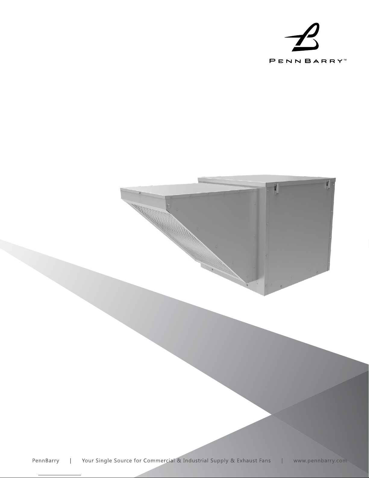
Muffan FS
Filtered Supply Fans
OPERATION & MAINTENANCE MANUAL
IMPORTANT! Read before proceeding!
Please read and save these instructions. Read carefully before attempting to
assemble, install, operate or maintain the product described. Protect yourself
and others by observing all safety information. Failure to comply with instructions
could result in personal injury and/or property damage! Retain instructions for
future reference.
1
Page 2

TABLE OF CONTENTS
INTRODUCTION 3
INSTALLATION 4-7
START-UP AND OPERATION 8
MAINTENANCE 9-10
TROUBLESHOOTING CHECKLIST 11
2
www.PennBarry.com
Page 3
INTRODUCTION
Receiving and Handling
PennBarry fans are carefully inspected before leaving the factory. When the unit is received, inspect the carton/crate for any signs of
tampering. Inspect the unit for any damage that may have occurred during transit and check for loose, missing or damaged parts.
Mishandled units can void the warranty provisions. If units are damaged in transit, it is the responsibility of the receiver to make all
claims against the carrier. PennBarry is not responsible for damages incurred during shipment.
Avoid severe jarring and/or dropping. Handle units with care to prevent damage to components or nishes. If the unit is scratched
due to mishandling, the protective coating may be damaged. Incorrect lifting may damage the fan and void the warranty.
Storage
Long-term storage requires special attention. Store units on a level, solid surface, preferably indoors. If outside storage is necessary,
protect the units against moisture and dirt by encasing the carton/crates in plastic or in some similar weatherproof material.
Periodically inspect units and rotate wheels to spread bearing lubricant. Failure to rotate wheels results in reduced bearing life and
may void the manufacturer’s warranty. If the unit will be stored for an extended time, remove belts. Belts which remain under tension
in a stationary position for extended periods are likely to have a reduced operating life.
Unpacking
Place the carton/crate in an upright position and remove the staples or use a sharp (knife edge) tool to carefully cut or scribe the
sealing tape on both sides at the top of the carton/crate. Open carton/crate aps. Remove any cardboard and wooden ller pieces,
as well as loose components or accessories shipped with the unit.
Carefully remove the unit from the carton/ crate. Inspect the unit for any damage that may have occurred during transit and check
for loose, missing or damaged parts.
www.PennBarry.com
3
Page 4

INSTALLATION
ROOF MOUNTING
The PennBarry FS is a fresh air supply fan. Accordingly, before installation, make sure that the unit is not located next to an exhaust
fan so that dirty or noxious air is not brought back inside the building. Mounting the unit on a roof necessitates prior installation of
the proper height and size roof curb. Curb must be installed securely and sealed carefully to the roof construction. Dampers, when
required, should be installed prior to mounting on the curb.
Dampers must be secured to the inside of the curb without undue twisting which may distort the damper frame. Damper frame
must be reasonably level on all sides. Check for free operation. If dampers are motor operated type, ascertain that proper voltage
is impressed on motor terminals.
POSITIONING AND RUNNING POWER LINES
Power is normally brought from within the building through proper conduit lines and placed inside one corner of the curb. It is
then fed through the clearance hole provided in the damper and, in turn, fed through the fan to the service switch, if furnished. The
number of wires, type of insulation and protection by metal rigid or exible conduit must be suitable for motor load on line voltage
service.
NOTE: Care should be taken to follow all local electrical safety and building codes. All electrical parts must be grounded, and grounding
conductor should be checked for continuity.
Some local codes prohibit the connection of in-line, aluminum fans in kitchen hood exhaust systems. According to present NFPA96
interpretation, ANY fan used in such duct work must be made of steel, with liquid-tight welds at all seams and connections. If local
codes are in accordance with NFPA96, do not use ANY FAN that is not completely welded closed for such duty. Refer to PennBarry’s
Fumex and Dynamo products for roof and wall mounted exhausters approved for use on kitchen hood exhaust systems.
ANCHORING AND SECURING THE FAN
Units should be seated on a properly sized curb. The gap between the base of the fan and the top of the curb should be sealed with a
neoprene 1” X 1/4” gasket. The gasket should be glued or attached with a pressure-sensitive adhesive. The fan must be rmly secured
to a metal curb with stainless steel or cadmium coated self-tapping screws, 18” on center. Units installed in areas subject to high
winds or unusual eld conditions may require additional fastening with guy wires. If the contractor removes the ventilator parts to
facilitate installation and electrical connections, all parts should be reassembled replacing all spacers, washers, nuts, bolts, fasteners
and components exactly as they were found prior to removal. All fasteners are to be drawn tight and secure.
4
www.PennBarry.com
Page 5

INSTALLATION
1
2B
2
2A
1A
2C
1
2
2B
2A
INTAKE HOUSING ASSEMBLY
(STANDARD) (REFER TO FIGURES 2 - 6)
1. Remove #1A to gain access to #2. Depending upon the HP factory supplied, #2 may be partially unassembled.
2. Cut or remove packaging as required. Carefully lift #2 out of #1. Determine if #2B is attached. If not, remove #2B from #1 and
attach to #2 via hardware as shown in gure 3.
3. Attach fully assembled #2 to #1 via hardware as shown in gure 3.
4. Remove #2A from #2 per gure 4. Install #2C lter(s) per gure 5. Re-attach #2A.
5. Caulk per gure 6. Re-install item #1A.
Figure 2
1
Figure 3
Figure 5 Figure 6
2
2C
2A
2B
1
3/16” silicone bead
all perimeter
2C
Figure 4
2
2A
2B
5
Table 1: Parts Reference
Ref. No. Description Qty.
1 Side Flo Muffan Assembly 1
1A Top 1
2 Intake Housing Assembly 1
2A Intake Housing Door 1
2B Intake Housing Bottom 1
2C Cleanable Filter 1 2*
Table 2: Parts Reference
Ref. No. Description Qty.
*FS10B, FS12B, FS15B, FS18B/FS20B
www.PennBarry.com
4 No. 10 - 5/8” Self Drive Screw 16/20*
5 1/4” - 20 X 3/4” Tumb Screw 3/4*
5
Page 6

INSTALLATION
INTAKE EXTENSION ASSEMBLY
(OPTIONAL) (REFER TO FIGURES 7 & 8)
1. Remove #3 and other loose parts from crating and packaging.
2. Blower housing (#1) must be attached to roof curb in order to x the intake height.
3. Lift and place #3 to opening of #1. Hold horizontal and provide temporary support underneath. Be certain that end of #3 closest
to #1 has solid side panels; holes in side panels (see detail A) are for legs located at the opposite end.
4. Secure #3 to #1 via hardware as shown in gure 7.
5. Assemble #3B to #3A via hardware as shown in gure 6 to complete a set of two legs. Note the legs must be assembled to be
right hand and left hand as shown in gure 7.
6. Locate proper holes on each leg to match pre-punched holes of #3A per detail A. Attach legs via hardware as shown in gure
7.
7. Attach #3C and #3D to #3A per detail B via hardware as shown in gure 7.
8. Attach #2 to #3 via hardware as shown in gure 7. Refer to instructions above for installing the Intake Housing Assembly for
details.
9. Caulk in two places as shown in gure 8.
3/16” silicone bead
all perimeter
3
3/16” silicone bead
1
1A
3A
3
1
3C
3D
3
Detail A Detail B
3C
3D
3A
3B
all perimeter
2
2C
2A
3B
2A
2B
6
3A
3C
3D
3A
3D
3A
www.PennBarry.com
Page 7

INSTALLATION
Table 3: Parts Reference
Ref. No. Description Qty.
1 Side Flo Muffan Assembly 1
1A Top 1
2 Intake Housing Assembly 1
2A Intake Housing Door 1
2B Intake Housing Bottom 1
2C Cleanable Filter 1 2*
Table 4: Parts Reference
Ref. No. Description Qty.
3 Intake Extension Assembly 1
3A Intake Extension Vertical Support 2
3B Intake Extension Horizontal Support 2
3C Intake Extension Horizontal Stiffener 1
3D Intake Extension Gusset 2
Table 5: Parts Reference
Ref. No. Description Qty.
4 No. 10-5/8 Self Drive Screw 3/4
5 1/4-20 X 3/4 Thumb Screw 3/4*
6 No. 10-1 Self Drive Screw 12/16*
7 1/4-20 Riv Nut 4/6**
8 1/4-20 X 3/4 Whiz Bolt 24/28*
9 1/4-20 Whiz Nut 20/24*
www.PennBarry.com
7
Page 8

START-UP AND OPERATION
Careful inspection should be made before starting up. Make sure that all instructions on labels are understood and executed. All
motor bolts should be securely tightened. Blower wheels should be rotated by hand to ensure free movement. Lock out power
supply before rotating wheel. The inlet louvers should be clean and free from obstruction.
Check condition of belts and the amount of tension prior to start-up. DO NOT overtighten, as bearing damage will occur.
Recommended belt tension should permit deection of 1/64” of the belt on each side of the belt measured halfway between the
pulley centerline. Exercise extreme care when adjusting belts as not to misalign the pulleys. Any misalignment will cause a sharp
reduction in belt life and produce squeaky, annoying noises. On units equipped with two or three groove pulleys, adjustments must
be made so that there is equal tension on all belts (see Figure 1).
Figure 1: Pulley Alignment & Tension
Whenever belts are removed or installed, never force belts over pulleys without loosening motor rst to relieve belt tension.
CAUTION
Before putting fan into operation, complete the following check list:
a. Lock out primary and secondary power source.
b. Make sure installation is in accordance with manufacturer’s instructions.
c. Check and tighten all fasteners.
d. Spin centrifugal wheel to see if rotation is free and doesn’t bind or rub.
e. Check all set-screws and keys; tighten if necessary.
f. Check belt for alignment (use recommended belt tension gauges).
g. Check belt for proper sheave selection (Make sure it is not in reverse position).
h. Make sure there is no foreign loose material in ductwork leading to and from fan or in the fan itself.
j. Properly secure all safety guards.
k. Secure all access doors to fan and ductwork.
l. Check line voltage with motor nameplate.
m. Check wiring.
(On single phase motors, the terminal block must be set up in accordance with the nameplate instructions and/or wiring
diagram. This set up must match the line voltage. If the motor is multi-speed or multivoltage, the winding leads must be
CAUTION
8
grouped and connected as shown on the motor wiring diagram. The line voltage must correspond with proper grouping of
motor leads. The wiring diagram must be followed explicitly or serious motor or starter damage will occur.)
www.PennBarry.com
Page 9

MAINTENANCE
Do not attempt maintenance on fan until the electrical supply has been completely disconnected. If a service switch has not been
provided, remove all fuses from the circuit and lock the fuse panel so they cannot be accidentally replaced.
Lubrication is a primary maintenance responsibility. Check all bearings periodically. Inspect belts for tightness. If the fan is installed in
a corrosive or dirty atmosphere, periodically clean the centrifugal wheel, inlet, motor housing and other moving parts.
FAN SHAFT LUBRICATION
Fan shaft bearing pillow blocks are furnished in the greasable type. The greasable type are factory greased eliminating the need
for greasing initially. Follow the lubricating schedule recommended by the factory. This practice should not supersede any safety
considerations.
Use low pressure grease guns only. High pressure guns tend to blow out or unseat bearing seals, leaving the bearing open
CAUTION
LUBRICATION SCHEDULE
Always follow the bearing manufacturer’s recommended lubrication schedule. If none is available, use the following general schedule.
a. Under average conditions where ambient temperatures do not exceed 120°F, lubrication is required 1 to 2 times a year
b. Under dirt laden atmosphere where there is a temperature range of 120°F to 150°F, lubrication is required from 3 to 6 times a
c. Under extreme temperature conditions and extremely dirty atmospheres, lubrication should be scheduled at least once or twice
to collect grime, dust and foreign particles.
year.
a month.
d. Belt drive units maximum temperature should not exceed 160°F. Direct driven models have temperature range stamped on
motor.
MOTOR LUBRICATION
In general, standard motors are furnished with pre-lubricated, sealed-for-life ball bearings which require no lubrication for 7 to 10
years of normal service. Where motors have been ordered with greasable bearings, these bearings are factory lubricated and require
no attention for one year under normal conditions. If grease relief ttings are provided, remove them when performing maintenance
to allow grease to ow out. Whenever possible, apply grease while the motor is running. This practice should not supersede any
safety considerations. DO NOT OVER-GREASE, as most lubricants deteriorate motor windings and thereby reduce motor life.
Table 6: Recommended Lubricants
Manufacturer Product Temp. Range
BP LG-#P-1
Gulf Gulfcrown EP-1
Imperial Oil Unirex EP-1
Shell Alvania R-1
BP Energrease, MPMK11
Gulf Gulfcrown EP-2
Imperial Oil Unirex EP-2
Shell Alvania R-3
Below 32°F (0°C)
32°F to 150°F (0°C to 66°C)
Sun Oil Sun Prestige 42
Texaco Regal AFB2
www.PennBarry.com
9
Page 10

MAINTENANCE
Filters
Filters are an integral part of the FS Muan. The lters are washable aluminum mesh with sizes and quantities per model listed
below. Filter inspection and cleaning intervals will vary depending upon the amount of contaminant present and when this will raise
the pressure drop across the lters to an unacceptable level. To clean the lters, rst remove the intake housing door marked 2A in
Figure 5. The lters can then be pulled up and out of the lter tracks through the top of the intake housing assembly. Use a brush or
vacuum for dry dust and contaminants. Then rinse with water in the opposite direction of airow through the lter. For contaminants
that are not easily removed with water, a light detergent can be used. Filters should be allowed to dry thoroughly and then placed
back within the lter tracks. Replace the intake housing door and all screws as originally found.
Special Purpose Systems
Environments that are explosive, corrosive, subject to high temperatures etc. may require special construction, inspection and
maintenance. It is necessary to observe the fan manufacturer’s recommendations and limitations concerning the type of material to
be handled by the fan and its application to special conditions.
Hidden Danger
In addition to the normal dangers of rotating machinery, fans present an additional hazard in their ability to suck in not only air, but
loose material as well. Solid objects can pass through the fan and be discharged by the impeller as potentially dangerous projectiles.
Therefore, screen intake to ductwork, whenever possible, to prevent the accidental entrance of solid objects. Never open access
doors to a duct system with the fan running.
On the downstream (or pressure) side of the system, releasing the door with the system in operation may result in an explosive
opening. On the upstream (or suction) side, the inow may be sucient to suck tools and clothing, etc., and may even cause a man
to lose his balance.
When a fan is being started for the rst time, a complete inspection of the duct work and interior of the fan should be made (with
the power locked o) to make certain there is no foreign material which can be sucked into or blown through the duct work.
Guards
All fans have moving parts which require guarding in the same way as other moving machinery. In areas which are accessible only
to experienced personnel, a standard industrial type guard may be adequate. This type of guard will prevent the entry of thrown or
dropped objects with a minimum restriction of airow.
Where the fan is accessible to untrained personnel or the general public, use maximum safety guards, even at the cost of some
performance loss. Unprotected fans located less than 7’ above the oor also require guarding as specied in the Occupational Safety
and Health Act (OSHA). Roof mounted equipment will require guards when access is possible.
Centrifugal fans may be connected directly to ductwork which will prevent contact with the internal moving parts, but when the inlet
or outlet is exposed, install a suitable guard. PennBarry Ventilation recommends the use of guards on all exposed non-ducted fans,
ceiling and wall mounted.
Replacement Parts
When replacing parts, do so with properly selected components which duplicate the original parts correctly. Incorrectly sized shafts,
belts, pulleys, centrifugal wheels, etc., can damage the fan.
Don’t decrease size of driven pulleys; overspreading will overload motors and blow wheels. Don’t increase size of driver pulleys. Don’t
change section “A” belts to “B” or single groove design to two groove type. Heavier belts require extra tension which will decrease
life of bearings. Don’t change type of lters especially to those of unknown eciency and loading capacity.
10
www.PennBarry.com
Page 11

TROUBLESHOOTING CHECKLIST
Symptom Possible Cause Corrective Action
1. Defective or Loose Motor Bearings 1. Replace Motor with Same Frame Size
2. Ventilator Base Not Securely Anchored 2. Reset Properly
Excessive Noise
3. Loose or Unbalanced Wheel/Propeller
4. Misaligned Pulleys or Shaft 4. Correct Alignment
5. Loose or Damaged Wheel/Propeller 5. Replace Wheel/Propeller
6. Wheel Running In Wrong Direction 6. Reverse Direction
1. Blown Fuse or Open Circuit Breaker 1. Replace Fuses or Circuit Breaker
3. Tighten Screws, Remove Build-Up, Balance Wheel/
Propeller
Fan Inoperative
Insufcient Airow
Water Leaking Into
Ductwork or Collection of
Grease Under Fan
Motor Overheating
2. Loose or Disconnected Wiring For Proper Connections 2. Shut Off Power and Check Wiring
3. Defective Motor 3. Repair or Replace Motor
4. Broken Belts 4. Replace Belts
1. Open Access Doors or Loose Sections of Ducts 1. Check for Leakage
2. Clogged Filters 2. Clean Filters
3. Operation in Wrong Direction 3. Correct Rotation of Wheel/Propeller
4. Insufcient Make-Up Air Direction 4. Add Make-Up Fan or Louver Opening
1. Fan Installed With Slope in the Wrong Direction 1. Slope Should Be Fitted in the Direction of the
2. Clogged Drain Spout 2. Clean Drain Spout
3. Cooling Tube or Motor Dome Top Removed 3. Install New Cooling Tube With Gasket and Dome Top
4. Grease Container Full 4. Empty Grease Box
1. Belt Slippage 1. Adjust Tension or Replace Bad Belts
2. Over Voltage Or Under Voltage 2. Contact Power Supply Company
3. Operation In Wrong Direction 3. Reverse Direction of Motor
4. Fan Speed Too High 4. Slow Down Fan By Opening Variable Pitch
5. Incorrect Motor (Service Factor 1.0, Low Ambient
Temperature)
5. Replace Motor With Correct Open, Nema Service
Factors (1.15 or Higher) with 40 Degrees Ambient
6. Blocked Cooling Tube Or Leaky Gasket 6. Remove Blockage And Seal Cooling Tube in Place
7. Insufcient Airow to Kitchen Hood Fan Operating
8. Undersized Motor
Note: Care should be taken to follow all local electrical, safety and building codes. Provisions of the National Electric Code (NEC), as wells as the
Occupational Safety and Health Act (OSHA) should be followed.
All motors are checked prior to shipment. If motor defects should develop, prompt service can be obtained from the nearest
authorized service station of the motor manufacturer while under warranty. Exchange, repair or replacement will be provided on a
no charge basis if the motor is defective within the warranty period. The PennBarry representative in your area will provide a name
and address of an authorized service station if requested. WARNING: Motor guarantee is void unless overload protection is provided
in motor wiring circuit.
www.PennBarry.com
7. Check Airow Under Hood and Adjust on Low Speed
with Kitchen In Full Operation
8. Check Motor Ratings with Catalog Speed and Air
Capacity Chart
11
Page 12

PennBarry is proud to be your preferred manufacturer of commercial and industrial fans and blowers. Learn how PennBarry can assist
you in your next application by contacting your PennBarry Representative or visiting us on the web at www.pennbarry.com.
PennBarry | www.pennbarry.com | pennbarrysales@pennbarry.com | tel: 972.212.4700 | fax: 972.212.4702
PennBarry reserves the right to make changes at any time, without notice, to models, construction, specications, options and
availability. This manual illustrates the appearance of PennBarry products at the time of publication.
View the latest updates on the PennBarry website.
© 2018 PennBarry. All Rights Reserved. Revised AUGUST 2018
 Loading...