

Page 1
INSTALLATION INSTRUCTIONS
STAND ALONE ERV
DXX-2ERV
D-SE RIES
ENERGY RECOVERY VENTILATOR SERIES D11, D20, D28, D36, D46, D62, D80 & D12
INSTALLATION INSTRUCTIONS FOR ENERGY RECOVERY VENTILATOR (FIXED)
FOR STAND ALONE ROOFTOP APPLICATION
Energy recovery COMPONENT certified
to the AHRI Air-to-Air Energy Recovery
Ventilation Equipment Certification
Program in accordance with AHRI
Standard 1060-2000. Actual performance
in packaged equipment may vary.
ETL Certified per UL 1995
and CSA 22.2
OCTOBER 6, 2015
SUPERCEDES 10-29-14
I - Ship ping and Pack ing List
Package contains:
1 — Energy Recovery Ventilator Assembly
1 — Assembled Exhaust Hood
II - Shipping Damage
Check the unit for shipping damage. Receiving party
should contact last carrier immediately if shipping damage
is found.
III - General
These instructions are intended as a general guide and do
not supersede local codes in any way. Authorities having
jurisdiction should be consulted before installation.
IV - Requirements
When installed, the unit must be electrically wired and
grounded in accordance with local codes or, in absence of
local codes, with the current National Electric Code,
ANSI/NFPA No. 70.
V - Application
These Energy Recovery Ventilators (ERVs) are used in a
down discharge manner equipped with a field provided
balancing damper assembly through the roof. A roof
curb must be provided by contractor to manufacturers
specifications. These ventilators conserve energy by
transferring humidity and heat energy across two opposing
air streams using a rotary heat exchanger (the energy
recovery wheel). This process works in the summer by
rejecting heat energy from incoming intake air and in the
winter by conserving heat energy from the exhaust air,
allowing outdoor ventilation rates to be increased by
factors of three or more without additional energy penalty
or increase in size of heating or air conditioning systems.
VI - Rigging for lifting
1. Maximum weight of the unit varies per series
(300-1200 lbs crated)
2. Remove crating
3. All panels must be in place for rigging.
4. Remove box containing screws and accessories from
the Controls section.
5. Duct work should be installed into roof curb before
installing ERV on curb.
6. Roof curb gasket should be applied to all top surfaces
of the curb. (refer to roof curb install instructions).
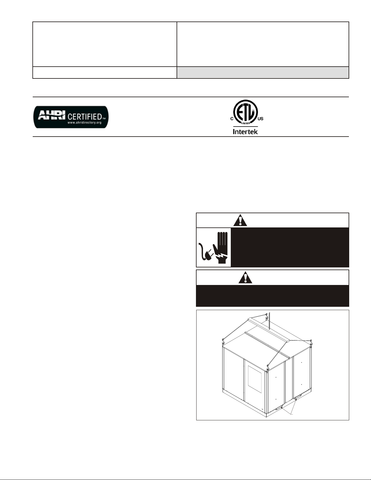
7. Forklift channels (if used) must be removed from the
base of the ERV before setting unit on curb. See
Figure 1.
8. Attach lifting straps to the provided lifting lugs on the
top 4 corners of the D-11 through D-62 units, on D-80
and D-120 units cutouts are provided on the bottom 4
corners for attachment of lifting straps.
9. Position unit on roof curb being sure to provide service
access to ERV control access door and wheel.
WARNING
Electric shock hazard. Can cause injury
or death. Before attempting to perform
any service or maintenance, turn the
electrical power to unit OFF at
disconnect switch(es). Unit may have
multiple power supplies.
CAUTION
Danger of sharp metallic edges. Can cause injury.
Take care when servicing unit to avoid accidental
contact with sharp edges.
FIGURE 1
FORKLIFT CHANNELS
PAGE 1
Page 2
VII - Installation
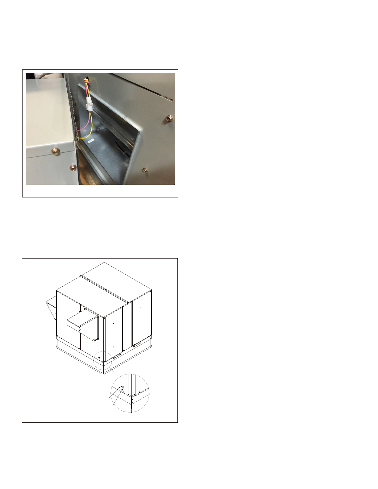
1. Install exhaust hood assembly shipped with ERV on
pallet using screws provided in accessory box. On
units with motorized exhaust damper connect Plug
(P.161) to jack after removing PK-3 jumper before
attaching hood with screws. See Figure 2.
FIGURE 2
2. Remove ERV control access panels to connect field
wiring.
Low Voltage
3. Route Class II low voltage wire (3 conductor) from
thermostat, relay, or Energy Management through
small bushing provided in the end panel in the ERV.
See Figure 3 for location of penetration.
THERMOSTAT PENETRATION
HIGH VOLTAGE KNOCKOUT
FIGURE 3
5. On units with Variable Frequency Drives a separate
terminal strip is provided to connect low voltage (0-10
VDC) controls [field supplied] for the Drives.
High Voltage
6. All Electrical connections must conform to any local
codes and current National Electric Codes (NEC) or
Canadian Electric Codes (CEC). Refer closely to unit
wiring diagram in the unit and/or in these instructions
for proper wiring connections.
7. Refer to unit nameplate for minimum circuit ampacity
(MCA) and maximum overcurrent protection size
(fuse).
8. Electrical data is listed on unit rating plate as well as
the motor name plates.
9. Connect line voltage power from field installed power
disconnect to ERV fuse block in the control box of the
unit. Use provided knockout on outside panel next to
controls section. See Wiring Diagram pg???
10. Ground unit with suitable ground connection
either through unit supply wiring or to an earth ground.
Note: Unit voltage entries must be sealed weather
tight after wiring is complete.
11. Remove motor access panels, check that blowers
have belts in place and that motors spin freely. Blower
RPM can be adjusted to meet CFM and external static
pressure requirements by adjusting the sheave on the
blower motors and by replacing the pulley kits on units
ordered without variable frequency drives. Multiple
pulley arrangements are available from the
manufacturer to meet the entire range of the units CFM
options.
Caution: Blower speed must be adjusted for the given
external static pressure and airflow (CFM)
requirements. If blower speed is not adjusted for
conditions, possible motor overloading can
occur.
12. Unit Startup. Turn on power disconnect, turn on unit
either from controls or by Jumping 24v+ from
transformer (blue low voltage wire) to terminal #1.
Check that motors are spinning the right direction (3
phase units only) that the enthalpy wheel is spinning
and that motorized intake air and exhaust dampers are
opening.
If unit is operating properly proceed to next step, if not
operating properly See Trouble shooting guide on
Page 4.
13. Clean up, caulk any open joints, holes or seams to
make the unit completely air and water tight. Remove
any jumpers, replace all access panels on the unit and
secure.
14. Leave this instruction manual with the owner or in an
envelope near the unit.
See System Check or Trouble shooting guide for
further information on the proper operation of the
ERV.
PAGE 2
Page 3

VIII - Stand Alone ERV Controls Schemes
Dependent options
Thermostat: This is the standard way to wire an ERV,
when the ductwork of the stand alone ERV is attached to
the ductwork of a single AC system the controls of the ERV
should be wired in parallel with the controls with "G" to 1,
"C" to 2 and "W" to 3. The ERV will operate when ever the
RTU's blower is operating.
Energy Management – Building Management Systems:
The ERV needs a 24 Volt AC signal to operate, connect the
24V+ to 1 and the 24V C to 2, the unit can be operated off of
a relay or BMS controller if necessary.
Dedicated options
When using a control method that does not involve an
outside 24V controls signal power can be borrowed from
the unit's transformer for short thermostat wire runs. Any
run over 150' however should be powered by a separate
transformer.
Thermostat: When using an ERV to service a large area
with multiple AC units or when not tying directly into the
ductwork of a single AC system the ERV can be run off of
its own Thermostat. Splice the 24V+ wire "R" onto the
XFORMER + terminal of the ERV control board, then wire
"G" and "C" onto terminals 1 and 2 respectively, program
Thermostat to energize G when space is occupied.
CO2 Sensor/ Transmitter: An ERV can be wired to a wall
mounted CO2 Sensor/ Transmitter with relay like Johnson
Controls CD-WR0-00-0 (or CD-WRD-00-0) in order to
operate the ERV when ventilation is required due to high
CO2 levels. This type of transmitter has an adjustable set
point, and a relay that the 24V+ signal can be wired into
and "G" wire can be wired out of. "G" should be wired to #1
terminal. The ERV will then turn on and provide fresh air to
the space to lower CO2 levels.
Quickstep: Units equipped with the Quick Step controls
option use an onboard microprocessor, factory installed
CO2 sensor and variable frequency drives to modulate
airflow through the ERV to control for Carbon Dioxide. To
operate the unit enter the Supply and Exhaust CFM values
(they do not have to be the same value) into the Quick Step
flexstat control along with maximum CO2 level and the
controls will modulate the blowers to ensure CO2 levels are
not above set point.
ON/OFF switch or Timer: Wire 24V+ from transformer
onto the input of the switch and connect the output of the
switch to terminal 1 on the control board. The ERV can be
turned on manually or be set to turn on at a regular
schedule when the building is occupied.
IX – Operation
How It Works.
The unit contains an energy recovery wheel (ERW) that is
a revolutionary concept in rotary air-to-air heat
exchangers. Designed as a packaged unit for ease of
installation and maintenance, only the connection of
electrical power is required to make the system
operational.
When slowly rotating through counter flowing exhaust and
fresh air streams the ERW absorbs sensible heat and
latent heat from the warmer air stream in the first half of its
rotation and transfers this total energy to the cooler air
stream during the second half of this rotating cycle.
Rotating at 50-60 RPM, the ERW provides a constant flow
of energy from the warmer to the cooler air stream. The
large energy transfer surface and laminar flow through the
ERW causes this constant flow of recovered energy to
represent up to 85% of the difference in total energy
contained within the two air streams.
Sensible and latent heat are the two components of total
heat, sensible heat is energy contained in dry air and latent
heat is the energy contained within the moisture of the air.
The latent heat load from the outdoor fresh air on an air
conditioning system can often be two to three times that of
the sensible heat load and in the winter it is a significant
part of a humidification heat load.
During both the summer and the winter, the ERW transfers
moisture entirely in the vapor phase. This eliminates wet
surfaces that retain dust and promote fungal growth as well
as the need for a condensate pan and drain to carry water.
Because it is constantly rotating when in the air stream, the
ERW is always being cleaned by air, first in one direction
and then the other. Because it is always dry, dust or other
particles impinging on the surface during one half of the
cycle are readily removed during the next half of the cycle.
During the heating season, when outdoor air temperatures
are below 15oF, it is recommended to use the (optional)
low ambient kit.
Optional Kits
Motorized Intake Air Damper
This damper mounts inside the outdoor air intake hood, it
opens when the ERV supply blower is energized and
closes when de-energized.
Motorized Exhaust Air Damper
Damper mounts inside the exhaust air hood, it opens when
the ERV is energize and closes when the ERV is
de-energized.
Pressure Sensors
Measurement devices (Magnahelics) on ERV that
measure pressure across the energy recovery wheel.
Rotation Sensor
A magnetic sensor and logic board that measure pulses
from a magnet on the spinning energy recovery wheel. A
lack of measured pulses after initial start up results in an
alarm. The alarm can be wired into building management
hardware or to a thermostat with alarm switch terminals, it
will warn that the wheel has stopped spinning, but does not
otherwise effect operation.
Stop, Start, Jog [Climate Smart]
This option adds an Economizer or free cooling mode to
the ERV. The wheel stops spinning to allow air to pass
without energy transfer, starting and spinning
intermittently in order to keep the wheel clean.
Low Ambient Kit
Prevents frost buildup on energy recovery wheel by
terminating intake air when the discharge air temperature
falls below a set level. Intake blower operation resumes
after a 16oF rise above the field adjustable set point.
The frost threshold is the outdoor temperature at which
frost will begin to form on the ERV wheel. For energy
recovery ventilators, the frost is typically below 10oF. Frost
threshold is dependent on indoor temperature and
humidity. The table shows how the frost threshold
temperatures vary depending on indoor conditions.
PAGE 3
Page 4

FROST THRESH OLD TEM PER A TURE
IN DOOR RH AT 70oF
20% 0oF
30% 5oF
40% 10oF
FROST THRESH OLD
TEM PER A TURE
Because energy recovery ventilators have a low frost
threshold, frost control options are not necessary in many
climates. The Low Ambient Kit is available for units
installed where outdoor temperatures may drop below the
frost threshold during the ERV operational hours.
Filter Racks/ Filter Options
Stand alone units come with return air filters standard,
MERV 8, 11, or 13 filters can be ordered with the unit.
Supply air filter racks can be added as an option with the
same efficiency filter options.
Dirty Filter Switches
Pressure differential switches that can be hooked up to an
alarm to alert when pressure drops across a filter bank
indicating dirty or clogged filter, they do not otherwise
effect operation.
Wheel Type
While the standard energy recovery wheel absorbs both
sensible and latent heat a sensible only wheel can be
ordered for applications where the sensible portion of the
heat load needs to be removed from a space without
returning the humidity.
Smoke Detector
Smoke detectors can be factory ordered with the ERV, a
qualified technician needs to field wire the smoke detector
into the controls to break common in case of alarm.
CO2 Sensor
See Quickstep in Controls schemes. A factory installed
Co2 sensor can be added to the unit to adjust ventilation on
a CO2 parts per million demand. This sensor is mounted
next to the return air inlet and is not a relay, it only provides
feedback to the quick step controls to adjust motor speed
and is not suitable to turn the unit on and off on CO
demand.
X – System Check
1. Disconnect main power
2. On units controlled by thermostats turn T-stat fan
switch to "On". Otherwise jump 24v+ to terminal #1.
3. Restore power to unit, observe ERV wheel rotation
and both fresh air and exhaust air blowers.
Note: If the low ambient kit is used the jumper between
terminals 5&6 should be removed and replaced
with blue and yellow wires for the sensor. If system
check out is being done at low ambient
temperatures this kit can cause the unit not to
operate. Under these conditions jump terminals
5&6.
4. Verify the ERV three phase blower motors are phased
sequentially ensuring correct rotation and operation. If
both blowers are running backwards:
A. Disconnect Power.
B. Reverse and two high voltage line in wires on the
ERVs fuse block.
C. Reapply Power.
Note: Blower Motor rotation is checked in factory, do
not switch wires at contactors or on motors if
blowers are spinning backwards at startup.
5. Verify that both blower motors are operating under
their full load AMP rating (FLA). The FLA can be found
on each motor and on the unit's name plate.
6. Verify that the fresh air and exhaust air motorized
dampers are opening and closing when unit turns
on/off.
Note: If unit is not operating properly refer to
troubleshooting guide.
7. Return damper settings. When tied into an HVAC
system manually adjust the position of the field
installed dampers to balance Air flow.
8. Static test ports are provided to verify intake and
exhaust CFM, these ports can also be used with a
temperature probe to verify temperature transfer
through the wheel.
Adjustment to the blower speed is accomplished by
changing the sheave setting on both fresh air and exhaust
air blowers.
Flow / Blower Speed Ad just ment
Blower speed selection is accomplished by changing the
sheave setting on both fresh air and exhaust air blowers.
To set ERV for the required air flow (CFM), the external
static pressure applied to the ERV (duct static) must be
known. See the CFM vs External Static Pressure chart for
the appropriate unit to determine the correct blower RPM
for the specified CFM and External Static Pressure.
After blower speed adjustments have been made. Ensure
that when the belt is replaced it is tensioned correctly. The
motor mounting plate can be adjusted to tension the belt. If
using a belt tension checker, adjust the span to the
appropriate setting and check the belt defection force. The
belt deflection force should be between 5-8 lbs or the
lowest tension at which the belt will not slip under peak load
conditions.
2
1. Disconnect main power to unit before making
adjustment to economizer and/or ERV unit.
2. Replace ERV control access cover.
3. Set thermostat to normal operating position.
4. Restore power to unit.
XI - Se quence of Op er a tion
1. The thermostat or Building Management System
(BMS), sends a 24 Volt AC signal to the HVAC system
for cooling, heating, fan only or ventilation operation.
2. The ERV is activated simultaneously with the blower of
the AC system. The intake air blower, the exhaust
blower and the enthalpy wheel motor of the ERV are
activated, these motors will remain energized as long
as the blower in the AC system is energized and the
outdoor conditions are adequate for energy recovery.
3. If the optional motorized intake air damper is present,
the damper must open causing a proving switch to
close in order to energize the intake air blower (10-20
seconds after the exhaust blower and enthalpy wheel
have started).
4. If the optional low ambient kit is present, and the
temperature leaving the exhaust side of the enthalpy
wheel is lower than the field adjusted set point on the
PAGE 4
Page 5

temperature sensor, the optional motorized fresh air
damper will close and the intake blower will
de-energize. The exhaust blower and enthalpy wheel
motor will continue to operate until the temperature
sensor has a 16F rise, at this point the enthalpy wheel
should be defrosted and the optional motorized
damper will open and the fresh air blower will
reactivate.
5. If the start, stop, jog [Climate Smart] option is present
and outside conditions are adequate for free cooling
the enthalpy wheel motor will stop for 10 minutes to
allow for cool air to enter the building. It will then start or
jog the wheel for 1 minute to keep dirt from building up
on the wheel.
XII - Trou ble Shoot ing guide
ERV will not op er ate:
1. Quick check items.
A. Verify that the door switch is closed, the switch
must be in the closed position in order to power
the control board.
B. Verify 24V power to the control board at terminals
Xformer + & -. If voltage is low check high voltage
into the unit (sec 2-A) and check that the T-1 wire
from the high voltage into the step down
transformer is on the correct terminal
(208v-230v-460V) for the units voltage.
C. Verify 24V to the control board's terminal strip at
T-1 (G) and T-2 (Com) in Fan or Cool or T-2 (Com)
and T-3 (W) in Heat. These terminals must be
powered by an external power source to
operate the ERV.
A jumper from Xformer + to T-1 can be used to test
operation of the ERV if an external 24V controls signal is
not available.
1. Verify high voltage to ERV
A. Verify that the unit has the proper voltage in at
terminals L1, L2 and/or L3 at the fused high
voltage connection terminal block. Voltage
specifications are on the units name plate.
B. Verify that the fuses are good, (check voltage
across fuses with power on, voltage should be 0)
replace any bad fuses.
ERV Has Power, But Motors Are Spinning Backwards
1. Motors are checked for proper rotation at the factory, if
the motors are spinning backwards after install
reverse the phase by switching two wires on the high
voltage IN terminals.
2. If the motor is spinning backwards after replacement
switch the L1 & L2 wires connected inside the motors
access panel. Do no rewire unit.
*Many of motors used in production of the ERVs are multi
voltage (230/460V) motors. When replacing motors or
diagnosing a motor that won't start. Care should be taken
to make sure the wires inside the motors access panel are
connected securely and in the proper configuration.
ERV Has Power, But the Enthalpy Wheel Does Not
Spin (Start Stop Jog #1)
1. If the unit has the Start, Stop, Jog option installed the
enthalpy wheel motor will turn off for 10 minute
intervals when outside conditions are optimal for free
PAGE 5
cooling, the fresh air and exhaust blowers will continue
running. The Start, Stop, Jog control board has a white
test button that when pressed will bypass the boards
logic and turn the enthalpy wheel on. See Start, Stop,
Jog in Options/Accessories troubleshooting for further
information.
2. With the power off, check that the wheel belt is in place
and tight.
3. Check for 24 volts between terminals Exhaust (K163)
A&B, if the unit doesn't have Start, Stop, Jog the relay
is connected directly to the Exhaust A and B terminals
on the control board. If terminals 1&2 or 3&2 are
energized with 24V, there is 24V in to Xformer + & - ,
and there is no voltage to Exhaust A&B the board is
bad.
4. If there is 24 Volts at Exhaust A&B trace wires to the
enthalpy wheel relay, check terminals A&B on the
Relay for 24 Volts, check for high voltage power into
and out of the relay. If the relay is energized/closed
and no power is passing from terminals 7 to 4 or 9 to 6
the relay is bad.
5. You can jump the enthalpy wheel relay to test its
operation by running a jumper from the 24v out on the
transformer (blue wire) to the A terminal on the relay
after removing the pink wire.
6. If the relay is closing and there is proper voltage
between terminals 4&6 on the relay check the wheel's
motor for proper voltage by using a multi-meter at Plug
P-150 next to the enthalpy wheel motor.
A. If voltage is present and this is a single phase
motor (most units) check the motor's capacitor.
B. If the capacitor is bad replace the capacitor,
continue testing the motor
C. If proper voltage is present and the capacitor is
good check the wires into the motor for continuity,
if there is no continuity through the windings a wire
connection is loose or the motor is bad, check wire
connections between harness and windings, if
connections are good the motor is bad, replace
motor.
ERV Has Power But the Exhaust Blower Does Not
Operate
1. With power off. On units with belts, check that the
blower's belt is tight and in place, if it is loose adjust the
motor or sheave to tighten it, if it is broken replace it.
2. Check the contactor (K-163) to see if the issue is with
high voltage or low voltage, if the contactor is closed
check the motor. If it is open, push closed to check that
the motor starts then check controls
3. Check for 24 Volts between Exhaust A&B terminals on
the control board.
A. If the controls are calling for operation but there are
not 24 Volts between Exhaust A&B the board is
bad.
B. If the controls are calling for operation and there
are 24 Volts between Exhaust A&B check the
yellow wire for direct connection to the proper
contactor (K-136), then check the pink wire for
continuity through the field installed exhaust
damper motor (if option was chosen) or the factory
installed plug (PK-3) at the Jack (J-161) located in
the exhaust blower section.
Page 6

3. If contactor is closed check voltage to the motor by
testing wires at Plug P-151, proper voltage is listed on
the unit's information tag. If there is proper voltage to
the motor and the motor is not spinning the motor is
bad. With single phase units check the capacitor, if
capacitor is bad replace it then continue checking the
motor.
ERV Has Power But The Intake Air Blower Does Not
Operate
1. With power off. On units with belts, check that the
blower's belt is tight and in place, if it is loose adjust the
motor or sheave to tighten it, if it is broken replace it.
2. Check the contactor (K-164) to see if the issue is with
high voltage or low voltage. If the contactor is closed
check the motor. If it is open, push closed to check that
the motor starts, then check controls.
3. If the contactor is open check for 24 Volts between
Fresh A&B terminals on the control board.
A. If the controls are calling for operation and there is
no voltage between Fresh A&B check terminals
5&6 to see if low ambient kit is installed (blue and
yellow wires installed instead of a jumper),
jumping terminals 5&6 will bypass the low ambient
sensor and energize terminals Fresh A&B. See
Low Ambient Kit in Options/Accessories
troubleshooting for further information.
B. If the controls are calling for operation and there is
no voltage between Fresh A&B and there is
continuity between terminals 5&6 then the board
is bad.
C. If the controls are calling for operation and
terminals Fresh A&B are energized but the
contactor is not energizing, check the yellow wire
from terminal Fresh B to contactor (K-164), check
the orange wire for continuity from terminal Fresh
A through factory installed fresh air damper plug
(P-160) to contactor. In models without a fresh air
damper option there should be an orange jumper
between pins 3&4 on the P-160 plug, when the
fresh air damper option is chosen these wires
connect to an end switch that is closed by a cam
when the fresh air damper opens. See Sequence
of Operations.
1. If contactor is closed check voltage to the motor by
testing wires at plug P-148, proper voltage is listed on
the unit's information tag. If there is proper voltage to
the motor and the motor is not spinning the motor is
bad. With single phase units check the capacitor, if
capacitor is bad replace it then check the motor.
ERV Has Power But The Motorized Fresh Air Damper
Does Not open
1. Verify 24V in between terminals 1&2 or 3&2
2. Check voltage at junction J-56 on the ERV control
board, there should be 24V between J-56 1&2 during
normal operation, If the unit has a low ambient kit
installed and temperatures are low the controls
de-energize J-56 and Fresh K-164 terminals on the
control board, jump Terminals 5&6 on the Terminal
strip to bypass see Low Ambient Kit in
Options/Accessories Troubleshooting for further
information.
3. If there is voltage at the control board check for 24V at
plug P-160 between pins 1&2
4. If there is voltage at P-160 make sure the damper
linkage isn't binding and that the wires are attached to
the actuator firmly. If the actuator still doesn't move
when 24V is applied replace the actuator.
ERV Has Power But The Motorized Exhaust Air
Damper Does Not Open
1. Verify 24V In between terminals 1&2 or 3&2
2. Check voltage at Exhaust A&B on control board
3. If there is voltage at Exhaust A&B on the control board,
trace wires to the exhaust blower compartment and
plug P-161, Check for 24V between Pins 1&3.
4. If there is 24V at plug P-161 make sure the field
connected P-161 plug for the damper is inserted firmly
into J-161, that the damper linkage isn't binding and
that the wires are connected firmly to the actuator. If
the damper actuator still does not move the actuator is
bad.
Options and Accessories Troubleshooting
Start, Stop, Jog [Climate Smart]
The Start, Stop, Jog kit is an optional control board with
temperature and/or enthalpy sensor(s) that stops the
enthalpy wheel from spinning (and transferring heat) when
temperature conditions are conducive for free cooling. The
board will spin the wheel intermittently in 10 min off 1 min
on intervals to keep dust from building up on the surface.
All units shipped with the Start, Stop, Jog option installed
have the temperature and enthalpy sensors installed, and
the jumper (J9) set to T(emp). A qualified tech can adjust
the setting to E(nthalpy) only or Temp and Enthalpy by
adjusting the jumper (J9).
The factory set points to allow for free cooling during
ventilation are 40F-70F, but they can be field adjusted to
narrow the band by adjusting two potentiometers while
measuring VDC between the Com & High or Com & Low
terminals (0 VDC = 40 degrees, low set point, 5 VDC = 70
degrees, high set point).
Low Ambient Kit
The low ambient kit is an optional temperature probe on a
normally closed switch that closes the fresh air damper
and turns off the fresh air blower when temperatures in the
blower compartment suggest a frosted enthalpy wheel.
The adjustable sensor is factory set for 20F. The sensor is
mounted in the blower compartment with its probe near the
blower's inlet, it is wired into the terminal strip 5&6
terminals.
It can be tested in hot weather by turning the dial up to a
higher temperature and checking to see if the normally
closed relay opens. In cold weather if the "R" terminal and
"W" terminal in the sensor show an open circuit the bulb
can be warmed above the set-point at which point the relay
should close.
Dirty Filter Switch
Dirty filter switches are an optional kit that put an
adjustable pressure switch with the Low inlet on the blower
side of the filter and the High inlet connected to the far side
of the filter via tubing. A dirty filter moves less air lowering
the pressure on the fan side Low inlet closing the normally
open sensor switch and allowing an alarm. The sensor(s)
are prewired into their own terminal strip and can be field
wired in series (normally closed), in parallel (normally
open) or individually to an alarm device.
PAGE 6
Page 7

Note: The Dirty Filter switch is not wired into the logic
of the ERV, it will not stop the ERV if filters are
dirty, it will only set off a field installed alarm or
warning that the filters are dirty and need to be
changed.
Pressure Gauge
An optional Magnahelic pressure gauge can be ordered as
an option to check pressure in In W.C., the Magnahelics
are factory installed in the doors of the ERV to give
pressure readings in the different quadrants of the unit.
Occasional re-zeroing of the gauge is required.
Rotation Sensor
The rotation sensor is an optional missing pulse detector
powered off of the exhaust and wheel 24v signal. A sensor
is mounted in the exhaust compartment near the wheel
and senses rotation via a magnet on the outside frame of
the wheel. Its output is wired to a terminal strip and an
alarm can be connected to alert when rotation of the wheel
has stopped.
If an alarm is going off and the wheel is rotating properly
check that the rotation sensor is mounted and adjusted to
properly sense the sensor magnet in the wheel. Check
wire connections to make sure they are secure.
If an alarm is tripped and the wheel is not rotating check the
wheels belt, it's motor, and capacitor for proper operation.
XIII - Main te nance
1. All motors use prelubricated sealed bearings; no
further lubrication is necessary.
2. Make visual inspection of motors, belts and wheel
rotating bearings during routine maintenance.
3. Eight pie-shaped segments, are seated on stops
between the segment retainer which pivots on the
wheel rim and secured to the hub and rim of wheel.
Annual inspection of the self cleaning wheel is
recommended. With power disconnected, remove
ERV access panels (rear) and unplug [J150 & P150]
(Refer to wiring diagram in this instruction
manual). Remove segment and wash with water
and/or mild detergent.
4. To install wheel segments follow steps A through E .
See Figure 4. Reverse procedure for segment
removal.
SEGMENT RETAINER CATCH
WHEEL RIM
E
SEGMENT RETAINER
A
A. Unlock two segment retainers (one on each side of
the selected segment opening.
B. With the embedded stiffener facing the motor side,
insert the nose of the segment between the hub
plates.
C. Holding segment by the two outer corners, press
the segment towards the center of the wheel and
inwards against the spoke flanges. If hand
pressure does not fully seat the segment, insert
the flat tip of a screw driver between the wheel rim
and outer corners of the segment and apply
downward force while guiding the segment into
place.
D. Close and latch each segment retainer under
segment retaining catch.
E. Slowly rotate the wheel 180o. Install the second
segment opposite the first for counterbalance.
Rotate the two installed segments 90o to balance
the wheel while the third segment is installed.
Rotate the wheel 180o again to install the fourth
segment opposite the third. Repeat this sequence
with the remaining four segments.
XIV - Pul ley Kit In stal la tion
The units are shipped from the factory at the low static
setting. Pulley kits are available for the medium and high
static settings. To install a pulley kit.
1. Check content of pulley kit, if pulley kit contains:
A. An adjustable sheave and a fixed pitch pulley then
remove belt and both motor and blower pulley.
B. An adjustable sheave then remove the motor
pulley.
C. A fixed pitch pulley then remove the blower pulley.
2. Replace pulley(s) with the pulley(s) from pulley kit.
Make sure each pulley is installed with a key. Tighten
the set screw on the pulley(s) to 100 in.lb.
3. Install the belt that came with the pulley kit. Tension
belt as explained in the blower speed adjustment
section.
4. Check the speed of the blower. Adjust the motor
sheave to increase or decrease the speed of the
blower. See blower adjustment section.
D
SPOKE
B
HUB
FIGURE 3
C
D
SEGMENT
PAGE 7
Page 8

D-02 Series Stand Alone ERV'S For Down Discharge Duct Arrangements
Features and Notes
1. Stand alone design allows higher levels of outdoor
air to be introduced into the a/c space.
2. Static test ports provided to verify intake and
exhaust CFM.
3. Balancing damper(s) field supplied in duct work when
connected to ERV.
4. Roof curbs are available for the ERV's.
5. See blower performance charts for airflow at various E.S.P..
6. Filter rack with 2" pleated filters included.
ERV Roof Curbs
Se ries Model No
D11 01- 2D1- 2514
D20 01- 2D1- 3014
D28 01- 2D1- 3614
D36 01- 2D1- 4114
D46 01- 2D1- 4614
D62 01- 2D1- 5214
D80 01-2D1-5814
D12 01-2D1-7414
A
D
B
EXHAUST HOOD
C
FRESH AIR HOOD
EXHAUST RETURN DUCT
(FIELD SUPPLIED)
E
F
4
FRESH AIR SUPPLY DUCT
G
EXHAUST
(FIELD SUPPLIED)
RETURN
J
FRESH AIR
SUPPLY
H
I
K
J
ERV Data Di men sional Data
ERV
Se ries
D11-02 300-1100 17.00 x 11.38 44.75 32.13 33.50 14.38 43.00 39.00 17.50 30.25 26.25 11.88 2.50
D20-02 1200-2000 21.88 x 14.00 54.38 37.25 37.50 17.50 52.75 48.75 22.38 35.50 31.50 14.50 2.50
D28-02 1200-2800 20.25 x 17.00 52.25 42.63 43.56 25.50 49.50 45.50 20.75 41.00 37.00 17.50 2.00
D36-02 2000- 3600 23.38 x 17.38 60.00 46.69 57.37 25.50 55.75 51.75 23.88 41.81 37.81 17.91 2.00
D46-02 3000- 4600 23.38 x 20.38 60.00 52.69 57.37 28.06 55.75 51.75 23.88 47.81 43.81 20.91 2.00
D62-02 4600- 6200 29.38 x 30.00 72.00 70.88 63.63 37.75 67.75 63.75 29.88 66.00 62.00 30.00 2.00
D80-02 6000-8000 38.75 x 35.38 101.38 78.38 71.34 21.75 99.75 95.75 38.75 76.75 72.75 35.38 2.00
D12-02 8000-13000 40.00 x 44.50 120.38 88.38 86.63 28.50 118.50 114.50 44.88 86.50 82.50 40.25 2.00
CFM Range
Duct Size
(G x J)
A B C D E F G H I J K
ERV Roof Curb
PAGE 8
Page 9

A131 Fixed Re lay Board
B26 Mo tor, Ex haust Air
B27 Mo tor, In take Air
B28 Mo tor, Desiccant Wheel
B30 Mo tor, Damper In take (Op tional)
B31 Mo tor, Damper Ex haust (Op tional)
C23 Ca pac i tor, Wheel Mo tor
C25 Ca pac i tor, Ex haust Air
C26 Ca pac i tor, In take Air
F29 Fuse
J48 Jack, Con trol Box (In take Air)
J50 Jack, Con trol Box (Wheel)
J51 Jack, Con trol Box (Ex haust Air)
J56 Jack, Con trol Box (Damper)
J148 Jack, In take Air Mo tor Har ness
J150 Jack, Wheel Mo tor Har ness
COMPONENT CODE
J151 Jack, Ex haust Air Mo tor Har ness
J160 Jack, Damper In take Mo tor Har ness
J161 Jack, Damper Ex haust Mo tor Har ness
K163 Contactor, Ex haust Air Mo tor
K164 Contactor, In take Air Mo tor
MPD-1 Miss ing Pulse De tec tor Board (Op tional)
P48 Plug, In take Air Mo tor Har ness
P50 Plug, Wheel Mo tor Har ness
P51 Plug, Ex haust Air Mo tor Har ness
P56 Plug, Damper Mo tor Har ness
P148 Plug, In take Air Mo tor
P150 Plug, Wheel Mo tor
P151 Plug, Ex haust Air Mo tor
P160 Plug, Damper In take Mo tor Har ness
P161 Plug, Damper Ex haust Mo tor Har ness
RS-1 Ro ta tion Sen sor (Op tional)
S26 Switch, Low Am bi ent (Op tional)
S51 Switch, Door
S52 Switch, Damper In take
S53 Switch, Damper Ex haust
SD Smoke De tec tor (Op tional)
SSJ Cli mate Smart Board (Op tional)
T27 Trans former, Con trol
T28 Trans former, Step-down (Op tional)
TB37 Ter mi nal Block (Low Volt age)
TB39 Ter mi nal Block (Mon i tor ing)
WHL Re lay, Wheel Mo tor
WIRE COLOR
CODE
BK Black
BL Blue
GR Green
GY Gray
OR Orange
PK Pink
RD Red
WT White
YL Yellow
D11-21-2ERV
PAGE 9
Notes:
1. Re move jumper to in stall field op tional low am bi ent switch.
2. Se lec tive volt age ter mi nal for proper unit volt age
3. Op tional low am bi ent switch.
4. Op tional mo tor ized in take damper.
5. Op tional Stop, Start and Jog Con trol (Cli mate Smart).
6. For en ergy man age ment sys tems con nect +24v to "G"
and com mon 24v to "C".
7. Op tional mo tor ized ex haust damper.
8. Op tional wheel ro ta tion sen sor.
9. Op tional smoke de tec tor.
Page 10

ERV UNIT WIR ING DIAGRAM
. "C" o t v42 nommoc dna
:setoN
.1 .hctiws tneibma wol lanoitpo dleif llatsni ot repmuj evomeR
.2 egatlov tinu reporp rof lanimret egatlov evitceleS
.3 .hctiws tneibma wol lanoitpO
.4 .repmad ekatni dezirotom lanoitpO
.5 .)tramS etami lC( lortnoC goJ dna tratS ,potS lanoi tpO
.6 "G" ot v42+ tcennoc smetsys tnemeganam ygrene roF
. 7 .r epmad t suahxe dezir o tom lanoit pO
. 8 .r o snes noitato r le ehw la noitpO
.9 .rotc ete d e k oms la n oitpO
PAGE 10
Desiccant Wheel for Rooftop Unit
208-230V (1 PH)
Unit#: 01-D11-02XX-21
Page 11

A131 Fixed Relay Board
B26 Motor, Exhaust Air
B27 Motor, Intake Air
B28 Motor, Desiccant Wheel
B30 Motor, Damper Intake (Optional)
B31 Motor, Damper Exhaust (Optional)
C23 Capacitor, Wheel Motor
F29 Fuse
J48 Jack, Control Box (Intake Air)
J50 Jack, Control Box (Wheel)
J51 Jack, Control Box (Exhaust Air)
J56 Jack, Control Box (Damper)
J148 Jack, Intake Air Motor Harness
J150 Jack, W heel Motor Harness
J151 Jack, Exhaust Air Motor Harness
J152 Jack, Transformer (High Voltage)
COMPONENT CODE
J160 Jack, Damper Intake Motor Harness
J161 Jack, Damper Exhaust Motor Harness
K163 Contactor, Exhaust Air Motor
K164 Contactor, Intake Air Motor
MPD-1 Missing Pulse Detector Board (Optional)
P48 Plug, Intake Air Motor Harness
P50 Plug, Wheel Motor Harness
P51 Plug, Exhaust Air Motor Harness
P56 Plug, Damper Motor Harness
P148 Plug, Intake Air Motor
P150 Plug, Wheel Motor
P151 Plug, Exhaust Air Motor
P152 Plug, Transformer (High Voltage)
P160 Plug, Damper Intake Motor Harness
P161 Plug, Damper Exhaust Motor Harness
RS-1 Rotation Sensor (Optional)
S26 Switch, Low Ambient (Optional)
S51 Switch, Door
S52 Switch, Damper Intake
S53 Switch, Damper Exhaust
SD Smoke Detector (Optional)
SSJ Climate Smart Board (Optional)
T27 Transformer, Control
T28 Transformer, Step-down (Optional)
TB37 Terminal Block (Low Voltage)
TB39 Terminal Block (Monitoring)
WHL Relay, Wheel Motor
WIRE COLOR
CODE
BK Black
BL Blue
GR Green
GY Gray
OR Orange
PK Pink
RD Red
WT White
YL Yellow
D11-D62-2ERV
Notes:
1. Remove jumper to install field optional low ambient switch.
2. Step-down transformer assembly for 460/575 volt units.
3. Selective voltage terminal for proper unit voltage
4. Optional low ambient switch.
5. Optional motorized intake damper.
6. Optional Stop, Start and Jog Control (Climate Smart).
7. For energy management systems connect +24v to "G" and common 24v to "C".
8. Optional motorized exhaust damper.
9. Optional wheel rotation sensor.
PAGE 11
Page 12

ERV UNIT WIR ING DIAGRAM
:setoN
.1 .hctiws tneibma wol lanoitpo dleif llatsni ot repmuj evomeR
.2 .stinu tlov 575/064 rof ylbmessa remrofsnart nwod-petS
.3 egatlov tinu reporp rof lanimret egatlov evitceleS
.4 .hctiws tneibma wol lanoi tpO
.5 .repmad ekatni dezi rotom lanoitpO
.6 . )t ramS etamilC( lor tnoC goJ dna t ratS ,potS l ano itpO
.01 .rotceted ekom s lanoitp O
.7 ."C" o t v42 nommoc dna "G" o t v42+ tcennoc sme ts ys tnemeganam y g r ene r oF
.8 .re pma d ts ua h xe d e zirotom la n oitpO
.9 .ro sn es n oitator lee h w lanoitpO
PAGE 12
Desiccant Wheel for Rooftop Unit
208-230/460/575V (3 PH)
Unit#: 01-D11-D62-02XX-23 thru -43
Page 13

ERV UNIT SCHE MATIC DIAGRAM
Notes:
1. Selective voltage terminals for proper unit voltage.
2. Remove jumper to install field optional low ambient switch.
3. Optional low ambient switch.
4. Optional motorized intake damper.
5. Optional Stop, Start and Jog Control.
6. Optional Motorized Exhaust Damper
7. For energy management systems connect +24v to "G" and common 24v to "C".
8. Optional Wheel Rotation Detection.
9. Optional Dirty Filter Sensors.
PAGE 13
D80-D12-2ERV
Page 14

ERV UNIT WIR ING DIAGRAM
Desiccant Wheel for Rooftop Unit
208-230/460/575V (3 PH)
Unit#: 01-D80-D12-02XX-23 thru -43
Notes:
1. Selective voltage terminals for proper unit voltage.
2. Remove jumper to install field optional low ambient switch.
3. Optional low ambient switch.
4. Optional motorized intake damper.
5. Optional Stop, Start and Jog Control.
6. Optional Motorized Exhaust Damper
7. For energy management systems connect +24v to "G" and common 24v to "C".
8. Optional Wheel Rotation Detection.
9. Optional Dirty Filter Sensors.
PAGE 14
Page 15

SUP PLY
CFM
EXHAUST
CFM
300
500
700
900
1100
300
500
700
900
1100
Blower RPM for D11
Mist Elimi na tor Fil ter in In take Hood (1.5HP)
Ex ter nal Static Pres sure (in wa ter)
0 0.25 0.5 0.75 1 1.25 1.5
N/A N/A 1175 1350 1450 1605 1730
N/A 1170 1340 1540 1655 1725 1840
1295 1425 1600 1625 1795 1960 2035
1540 1660 1720 1790 2030 2110 2195
1785 1915 2025 2185
Ba ro met ric Hood, 2" Pleated Fil ters (1.5HP)
Ex ter nal Static Pres sure (in wa ter)
0 0.25 0.5 0.75 1 1.25 1.5
N/A N/A 1030 1225
N/A 1025 1180 1265 1425 1535
1120 1190 1340 1445 1540 1645 1720
1285 1525 1500 1575 1670 1785 1865
1570 1665 1670 1775 1860 1920
N/A N/A N/A
n/a n/a n/a
n/a
N/A
Notes:
1. Drive losses included in the above tables.
2. Performance can vary depending on ambient conditions.
3. Blower RPMs are for reference only.
Blower RPM for D20
SUP PLY
Mist Elimi na tor Fil ter in In take Hood (2HP)
0 0.25 0.5 0.75 1 1.25 1.5
1055 1135 1295 1420 1540 1650 1725
1140 1240 1340 1490 1600 1690 1795
1200 1330 1460 1565 1645 1740 1830
1320 1405 1525 1615 1705 1785 1885
1415 1515 1605 1690 1775 1875 1960
Ba ro met ric Hood, 2" Pleated Fil ters (2HP)
0 0.25 0.5 0.75 1 1.25 1.5
1010 1195 1350 1445 1580 1685 1735
1125 1315 1435 1545 1620 1730 1800
1185 1370 1500 1610 1695 1790 1965
1305 1485 1600 1685 1781 1955 2030
1410 1550 1670 1765 1855
CFM
EXHAUST
CFM
1200
1400
1600
1800
2000
1200
1400
1600
1800
2000
RPM Range
Low 1000- 1300 Stan dard Unit
Me dium 1300- 1700 Op tional Kit
High 1750-2200 Op tional Kit
Ex ter nal Static Pres sure (in wa ter)
Ex ter nal Static Pres sure (in wa ter)
N/A N/A
Notes:
1. Drive losses included in the above tables.
2. Performance can vary depending on ambient conditions.
3. Blower RPMs are for reference only.
RPM Range
Low 1000- 1300 Stan dard Unit
Me dium 1300- 1700 Op tional Kit
High 1700- 2080 Op tional Kit
PAGE 15
Page 16

SUP PLY
CFM
EXHAUST
CFM
1200
1600
2000
2400
2800
1200
1600
2000
2400
2800
Blower RPM for D28
Mist Elimi na tor Fil ter in In take Hood (3HP)
Ex ter nal Static Pres sure (in wa ter)
0 0.25 0.5 0.75 1 1.25 1.5
N/A 790 960 1110 1210 1315 1380
750 900 1005 1145 1230 1365 1410
900 1005 1105 1210 1275 1400 1450
1005 1125 1210 1275 1365 1450 1500
1125 1230 1315 1380 1450 1535 1600
Ba ro met ric Hood, 2" Pleated Fil ters (3HP)
Ex ter nal Static Pres sure (in wa ter)
0 0.25 0.5 0.75 1 1.25 1.5
750 885 1015 1145 1260 1350 1485
870 1015 1125 1215 1325 1410 1500
1015 1145 1240 1345 1410 1485 1560
1125 1250 1345 1430 1500 1575 1630
1250 1410 1485 1520 1630 1650 1675
Notes:
1. Drive losses included in the above tables.
2. Performance can vary depending on ambient conditions.
3. Blower RPMs are for reference only.
Blower RPM for D36
SUP PLY
Mist Elimi na tor Fil ter in In take Hood (3HP)
0 0.25 0.5 0.75 1 1.25 1.5
725 825 900 1000 1070 1180 1250
800 900 1000 1070 1160 1250 1275
900 1000 1070 1160 1250 1275 1340
1000 1070 1160 1250 1275 1340 1400
1055 1180 1250 1300 1360
Ba ro met ric Hood, 2" Pleated Fil ters (3HP)
0 0.25 0.5 0.75 1 1.25 1.5
750 865 950 1030 1100 1200 1265
820 950 1035 1100 1200 1265 1300
925 1035 1150 1200 1265 1315 1350
1035 1160 1215 1265 1325 1350 1390
1100 1215 1300 1350 1390
CFM
EXHAUST
CFM
2000
2400
2800
3200
3600
2000
2400
2800
3200
3600
RPM Range
Low 750-975 Stan dard Unit
Me dium 1008-1314 Op tional Kit
High 1311-1708 Op tional Kit
Ex ter nal Static Pres sure (in wa ter)
N/A N/A
Ex ter nal Static Pres sure (in wa ter)
N/A N/A
Notes:
1. Drive losses included in the above tables.
2. Performance can vary depending on ambient conditions.
3. Blower RPMs are for reference only.
RPM Range
Low 725-975 Stan dard Unit
Me dium 1000-1315 Op tional Kit
High 1215-1425 Op tional Kit
PAGE 16
Page 17

SUP PLY
CFM
EXHAUST
CFM
3000
3400
3800
4200
4600
3000
3400
3800
4200
4600
Blower RPM for D46
Mist Elimi na tor Fil ter in In take Hood (5HP)
Ex ter nal Static Pres sure (in wa ter)
0 0.25 0.5 0.75 1 1.25 1.5
900 1030 1100 1165 1240 1285 1350
975 1085 1175 1240 1290 1350 1400
1070 1175 1240 1290 1350 1400 1465
1165 1240 1320 1350 1430 1465 1515
1240 1320 1375 1430 1500 1515 1580
Ba ro met ric Hood, 2" Pleated Fil ters (5HP)
Ex ter nal Static Pres sure (in wa ter)
0 0.25 0.5 0.75 1 1.25 1.5
955 1100 1160 1245 1280 1360 1425
1055 1185 1245 1300 1375 1425 1480
1160 1300 1360 1400 1425 1530 1585
1245 1375 1450 1480 1500 1585 1650
1360 1450 1500 1585 1600 1650 1700
Notes:
1. Drive losses included in the above tables.
2. Performance can vary depending on ambient conditions.
3. Blower RPMs are for reference only.
Blower RPM for D62
SUP PLY
Mist Elimi na tor Fil ter in In take Hood (5HP)
0 0.25 0.5 0.75 1 1.25 1.5
815 900 975 1045 1085 1125 1175
880 940 1015 1060 1135 1175
915 975 1045 1125 1150
975 1045 1085 1175
1000 1075 1165
Ba ro met ric Hood, 2" Pleated Fil ters (5HP)
Ex ter nal Static Pres sure (in wa ter)
0 0.25 0.5 0.75 1 1.25 1.5
825 915 1000 1025 1100 1140 1170
890 975 1025 1100 1140 1170 1240
925 1000 1085 1140 1170 1240 1280
975 1025 1140 1170 1240
1025 1120 1170
CFM
EXHAUST
CFM
4600
5000
5400
5800
6200
4600
5000
5400
5800
6200
RPM Range
Low 780- 1020 Stan dard Unit
Me dium 1000- 1315 Op tional Kit
High 1315- 1700 Op tional Kit
Ex ter nal Static Pres sure (in wa ter)
1215
1195 1250
1250 1260 N/A
1200 N/A N/A N/A
N/A N/A
N/A N/A N/A N/A
Notes:
1. Drive losses included in the above tables.
2. Performance can vary depending on ambient conditions.
3. Blower RPMs are for reference only.
RPM Range
Low 820- 1000 Stan dard Unit
Me dium 1000- 1200 Op tional Kit
High 1175- 1375 Op tional Kit
PAGE 17
Page 18

SUP PLY
CFM
EXHAUST
CFM
6000
6400
6800
7200
7600
8000
6000
6400
6800
7200
7600
8000
Blower RPM for D80
Mist Elimi na tor Fil ter in In take Hood (10HP)
Ex ter nal Static Pres sure (in wa ter)
0 0.25 0.5 0.75 1 1.25 1.5
737 794 851 908 961 1012 1061
786 839 893 947 998 1047 1094
836 886 937 987 1036 1083 1129
885 931 979 1027 1074 1119 1163
934 978 1024 1069 1114 1159 1200
983 1025 1068 1111 1154 1196 1237
Ba ro met ric Hood, 2" Pleated Fil ters (7.5HP)
Ex ter nal Static Pres sure (in wa ter)
0 0.25 0.5 0.75 1 1.25 1.5
599 660 716 769 818 866 911
639 695 748 798 846 892 935
679 733 783 831 877 921 963
719 769 817 863 907 949 990
759 808 854 897 940 980 1020
799 845 889 931 972 1011 1049
Notes:
1. Drive losses included in the above tables.
2. Performance can vary depending on ambient conditions.
3. Blower RPMs are for reference only.
Blower RPM for D12
SUP PLY
Mist Elimi na tor Fil ter in In take Hood (15HP)
0 0.25 0.5 0.75 1 1.25 1.5
427 470 512 552 591 630 667
469 509 547 584 621 656 691
512 548 583 618 651 684 717
555 589 621 653 684 715 746
597 629 659 689 718 747 776
640 670 698 726 754 781 808
Ba ro met ric Hood, 2" Pleated Fil ters (15HP)
0 0.25 0.5 0.75 1 1.25 1.5
437 480 521 551 600 639 676
481 520 558 595 631 665 701
525 561 596 630 663 696 728
569 602 634 665 657 727 758
612 643 674 703 732 761 789
656 685 713 741 768 795 822
CFM
EXHAUST
CFM
8000
8800
9600
10400
11200
12000
8000
8800
8600
10400
11200
12000
RPM Range
Low Stan dard Unit
Me dium Op tional Kit
High Op tional Kit
Ex ter nal Static Pres sure (in wa ter)
Ex ter nal Static Pres sure (in wa ter)
Notes:
1. Drive losses included in the above tables.
2. Performance can vary depending on ambient conditions.
3. Blower RPMs are for reference only.
RPM Range
Low Stan dard Unit
Me dium Op tional Kit
High Op tional Kit
PAGE 18
Page 19

PAGE 19
Page 20

START UP INFORMATION SHEET
VOLTAGE - ERV UNIT
In com ing Volt age L1-L2 L1-L3 L2-L3
Run ning Volt age L1-L2 L 1-L3 L2-L3
Sec ond ary Volt age C (black) to G (green) Volts*
C (black) to W (white) Volts*
* With thermostat calling.
AM PER AGE - ERV MO TORS
In take Mo tor: Nom i nal HP Rated Amps Run ning Amps
Ex haust Mo tor: Nom i nal HP Rated Amps Run ning Amps
Wheel Mo tor: Nom i nal HP Rated Amps Run ning Amps
AIRFLOW
In take De sign CFM Pres sure Drop Cal cu lated CFM
Ex haust De sign CFM Pres sure Drop Cal cu lated CFM
Amb. db Temp Re turn Air db Temp* Tem pered Air db Temp*
Amb. wb Temp Re turn Air wb Temp* Tem pered Air wb Temp*
* Measure after 15 minutes of run time
INSTALLATION CHECK LIST
Model # Se rial #
Owner Owner Phone #
Owner Ad dress
In stall ing Con trac tor Start Up Me chanic
q Inspect the unit for transit damage and report any damage on the carrier's freight bill.
q Check model number to insure it matches the job requirements.
q Install field accessories and unit adapter panels as required. Follow accessory and unit installation manuals.
q Verify field wiring, including the wiring to any accessories.
q Check all multi-tap transformers, to insure they are set to the proper incoming voltage.
q Verify correct belt tension, as well as the belt/pulley alignment. Tighten if needed.
q Prior to energizing the unit, inspect all the electrical connections.
q Power the unit. Bump the motor contactor to check rotation. Three phase motors are synchronized at the
factory. If blower motor fans are running backwards, de-energize power to the unit, then swap two of the three
incoming electrical lines to obtain proper phasing. Re-check.
q Perform all start up procedures outlined in the installation manual shipped with the unit.
q Fill in the Start Up Information as outlined on the opposite side of this sheet.
q Provide owner with information packet. Explain the thermostat and unit operation.
PAGE 20
 Loading...