

Page 1
INSTALLATION INSTRUCTIONS
MV75-2ERV
SUPERSEDES 10-05-11
JUNE 4, 2012
EN ERGY RE COV ERY WHEEL
INSTALLATION INSTRUCTIONS FOR MINI VENTILATOR (MV) WITH FACTORY INSTALLED OPTIONS
(LOW AMBIENT, ROTATION SENSOR AND CLIMATE SMART [PATENT PENDING])
USED AS A STAND ALONE OR WITH SPLIT SYSTEMS UNITS
Energy recovery COMPONENT
certified to the AHRI Air-to-Air
Energy Recovery Ventilation
Equipment Certification Program in
accordance with AHRI Standard
1060-2000. Actual performance in
packaged equipment may vary.
ETL Certified per UL 1995
and CSA 22.2
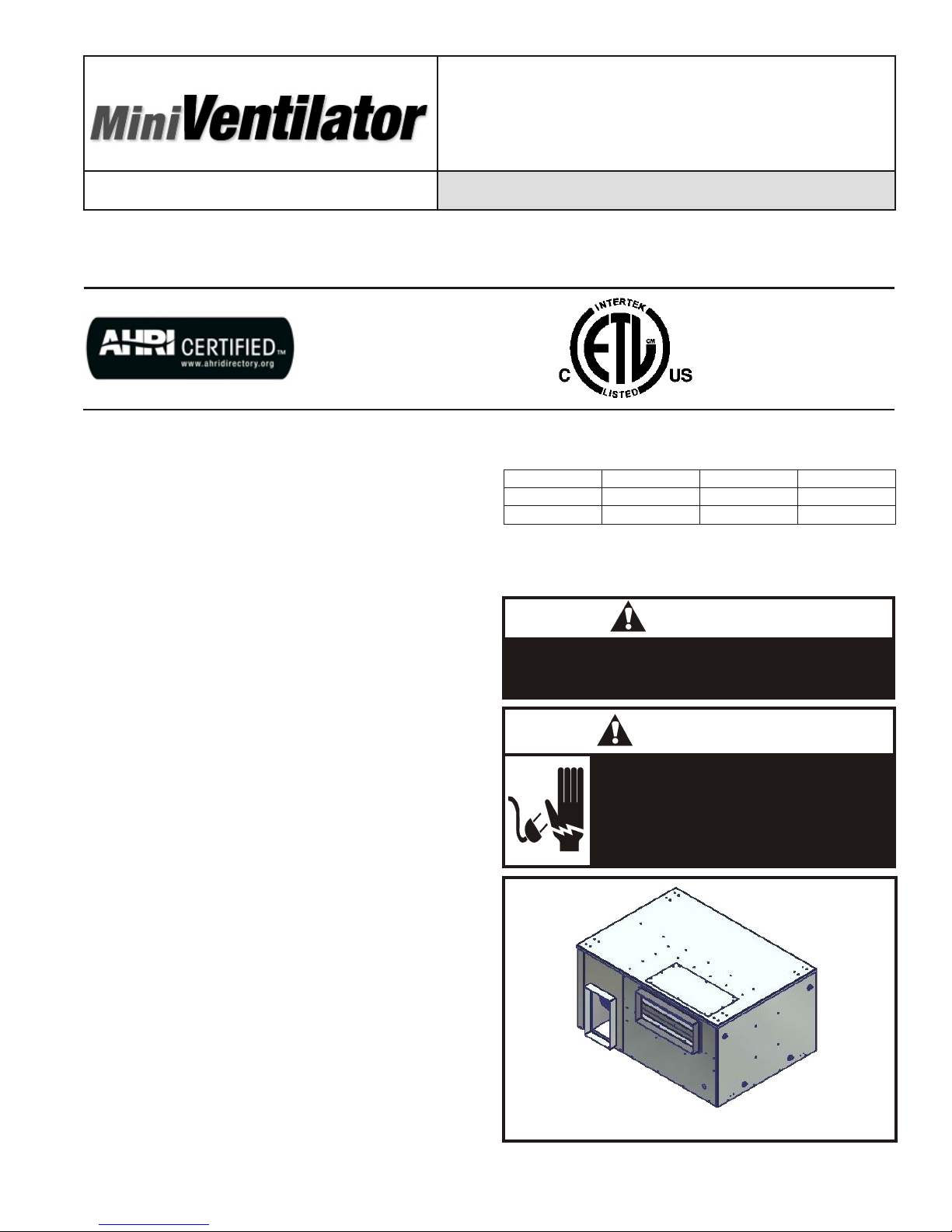
I - Ship ping And Pack ing List
Package 1 of 1 contains:
1 - Mini Ventilator Assembly (See Figure 1)
II - Ship ping Dam age
Check unit for shipping damage. Receiving party should
contact last carrier immediately if shipping damage is
found.
III - Gen eral
These instructions are intended as a general guide and do
not supersede local codes in any way. Authorities having
jurisdiction should be consulted before installation.
IV - Re quire ments
When installed, the unit must be electrically wired and
grounded in accordance with local codes or, in the
absence of local codes, with the current National Electric
Code, ANSI/NFPA No. 70.
V - Ap pli ca tion
Mini Ventilators (MV) are used as stand alone. These
ventilators conserve energy by mixing warmer air with
cooler air in the following manner:
Re cov ery Wheel Mode
The Recovery Wheel mode is accomplished by two
blowers providing continuous exhaust of stale indoor air
and replacement by equal amount of outdoor air. Energy
recovery is achieved by slowly rotating the energy
recovery wheel within the cassette frame work. In winter,
the MV adsorbs heat and moisture from the exhaust air
stream during one half of a complete rotation and gives
them back to the cold, drier intake air supply during the
other half rotation. In summer, the process is automatically
reversed. Heat and moisture are absorbed from incoming
intake air supply and transferred to the exhaust air stream.
This process allows outdoor air ventilation rates to be
increased by factors of three or more without additional
energy penalty or increase in size of heating or air
conditioning systems.
VI - Rig ging Unit For Lift ing
1. Maximum weight of unit is
Model# C25 / MV250 C45 / MV450 C75 / MV750
Net Weight 195 195 225
Ship Weight 215 215 261
2. Remove carton.
3. All panels must be in place for rigging.
CAUTION
Danger of sharp metallic edges. Can cause injury.
Take care when servicing unit to avoid accidental
contact with sharp edges.
WARNING
Electric shock hazard. Can cause injury
or death. Before attempting to perform
any service or maintenance, turn the
electrical power to unit OFF at
disconnect switch(es). Unit may have
multiple power supplies.
Figure 1
PAGE 1
Page 2

VII - In stal la tion
The unit can be installed using two different intakes
general configurations. The unit is shipped in horizontal
intake configuration. Please refer to the following diagrams
for installation instructions:
Note: All duct work and flex connectors are field
supplied.
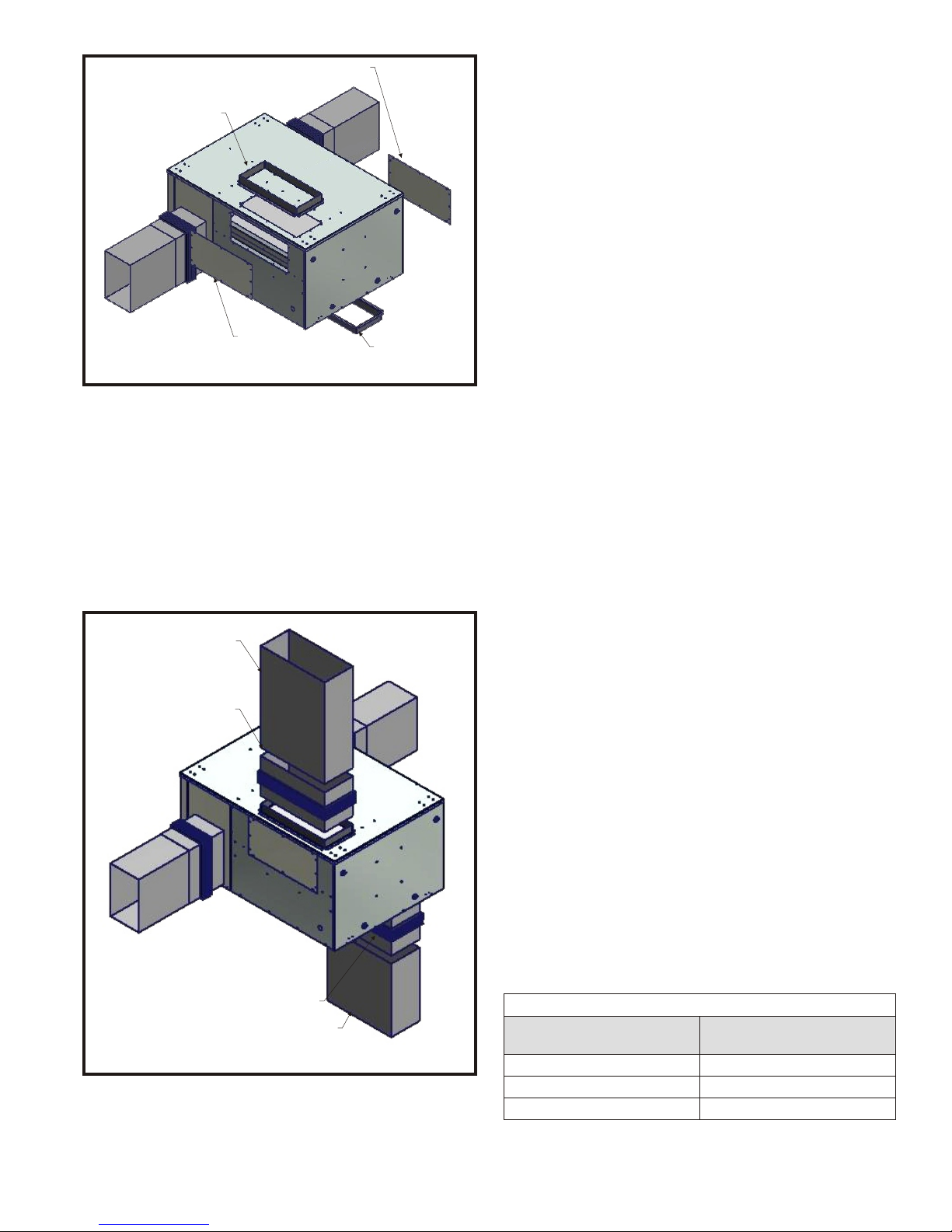
A - Hor i zon tal Configuration Duct Work In stal la tion
1. Attach Flexible Duct Collar to the MV fresh air intake
and secure with screws. See Figure 2.
2. Attach fresh air supply duct work to fresh air supply
Flexible Duct Collar and secure with screws. See
Figure 2.
3. Attach Flexible Duct Collar return air exhaust and
secure with screws. See Figure 2.
4. Attach return air exhaust duct work to return air
exhaust Flexible Duct Collar and secure with screws.
See Figure 2.
RE TURN AIR EX HAUST
RE TURN AIR EX HAUST
FLEX I BLE DUCT COLLAR
DUCT WORK
RE TURN AIR INTAKE
FLEX I BLE DUCT COLLAR
RE TURN AIR INTAKE
DUCT WORK
FRESH AIR INTAKE
FRESH AIR INTAKE
DUCT WORK
FLEX I BLE DUCT COLLAR
Figure 3
4. Attach return air exhaust duct work to return air
exhaust Flexible Duct Collar and secure with screws.
See Figure 2.
5. Remove fresh air intake duct collar from lateral intake.
See Figure 4.
6. Remove return air intake duct collar from lateral
intake. See Figure 4.
FRESH AIR SUPPLY
FRESH AIR SUPPLY
DUCT WORK
FLEX I BLE DUCT COLLAR
Figure 2
5. Attach Flexible Duct Collar to MV fresh air intake and
secure with screws. See Figure 3.
6. Attach fresh air intake duct work to fresh air intake
Flexible Duct Collar and secure with screws. See
Figure 3.
7. Attach Flexible Duct Collar to return air intake and
secure with screws. See Figure 3.
8. Attach return air intake duct work to return air intake
Flexible Duct Collar and secure with screws. See
Figure 3.
B - Top/Bottom Configuration Duct Work Installation
1. Attach Flexible Duct Collar to the MV fresh air intake
and secure with screws. See Figure 2.
2. Attach fresh air supply duct work to fresh air exhaust
Flexible Duct Collar and secure with screws. See
Figure 2.
3. Attach Flexible Duct Collar return air exhaust and
secure with screws. See Figure 2.
7. Remove cover panel from top fresh air intake. See
Figure 4.
8. Remove cover panel from bottom return air intake.
See Figure 4.
RE TURN AIR INTAKE
DUCT COLLAR
FRESH AIR INTAKE
COVER PANEL
FRESH AIR INTAKE
DUCT COLLAR
Figure 4
RETURN AIR INTAKE
COVER PANEL
9. Attach fresh air duct collar to top fresh air intake and
secure with provided screws. See Figure 5.
10. Attach return air duct collar to bottom return air intake
and secure with provided screws. See Figure 5.
11. Attach fresh air cover panel to lateral fresh air intake
and secure with provided screws. See Figure 5.
12. Attach return air cover panel to lateral return air intake
and secure with provided screws. See Figure 5.
PAGE 2
Page 3
RE TURN AIR IN TAKE
COVER PANEL
FRESH AIR IN TAKE
DUCT COL LAR
FRESH AIR INTAKE
COVER PANEL
Figure 5
RE TURN AIR INTAKE
DUCT COLLAR
13. Attach Flexible Duct Collar to the MV fresh air intake
and secure with screws. See Figure 6.
14. Attach fresh air intake duct work to fresh air intake
Flexible Duct Collar and secure with screws. See
Figure 6.
15. Attach Flexible Duct Collar to return air intake and
secure with screws. See Figure 6.
16. Attach return air intake duct work to return air intake
Flexible Duct Collar and secure with screws. See
Figure 6.
FRESH AIR IN TAKE
DUCT WORK
FRESH AIR IN TAKE
FLEX I BLE DUCT COL LAR
VIII - Op er a tion
How It Works
The unit contains an Mini Ventilator that is a new concept in
a rotary air-to-air heat exchanger. Designed as a
packaged unit for ease of installation and maintenance,
only connection of electrical power is required to make the
system operational. The concept consists of a unique
rotary energy recovery wheel that rotates in and out of
fresh air streams within a heavy duty, permanently
installed blower cabinet that provides ready access to all
internal components. The Energy Recovery Wheel
contains spirally wound polymeric material that is coated
and permanently bonded with a silica gel desiccant for
transfer of sensible and latent heat. The wheel is belt
driven by one motor and stretch urethane perimeter drive
belt.
When slowly rotating through counter flowing exhaust and
intake air streams the MV adsorbs sensible heat and latent
heat from the warmer air stream and transfers this total
energy to the cooler air stream during the second half of its
rotating cycle. Rotating the wheel provides constant flow of
energy from warmer to cooler air stream. The large
energy transfer surface and laminar flow through the wheel
causes this constant flow of recovered energy to
represent up to 85% of the difference in total energy
contained within the two air streams.
Sensible and latent heat are the two components of total
heat. Sensible heat is energy contained in dry air and latent
heat is the energy contained within the moisture of the air.
The latent heat load from the outdoor fresh air on an air
conditioning system can often be two to three times that of
the sensible heat load and in the winter it is a significant
part of a humidification heat load.
During both the summer and winter, the MV transfers
moisture entirely in the vapor phase. This eliminates wet
surfaces that retain dust and promote fungal growth as well
as the need for a condensate pan and drain to carry water.
Because it is constantly rotating when in the air stream, the
MV is always being cleared by air, first in one direction
then the other. Because it is always dry, dust or other
particles impinging on the surface during one half cycle,
are readily removed during the next half cycle.
RE TURN AIR INTAKE
FLEX I BLE DUCT COLLAR
RE TURN AIR INTAKE
DUCT WORK
Figure 6
PAGE 3
In the heating season, when outdoor air temperatures are
below 10oF, it is recommended to use the (optional) low
ambient kit (factory installed 02 models only). At these
conditions you will need to determine the frost threshold
parameters.
The frost threshold is the outdoor temperature at which
frost will begin to form on the MV wheel. For energy
recovery ventilators, the frost threshold is typically below
10oF. Frost threshold is dependent on indoor temperature
and humidity. The table shows how the frost threshold
temperatures vary depending on indoor conditions.
FROST THRESH OLD TEM PER A TURE
IN DOOR RH AT 70oF
FROST THRESH OLD
TEM PER A TURE
20% 0oF
30% 5oF
40% 10oF
Page 4
Because Mini Ventilators have a low frost threshold, frost
control options are not necessary in many climates. Where
outdoor temperatures may drop below the frost threshold
during the MV operational hours, exhaust only frost control
option is available.
IX - Standard Features
Low Am bi ent Kit
Extremely cold outdoor air temperatures can cause
moisture condensation and frosting on the energy
recovery wheel (ERW). The outside temperature below
which frost will begin to accumulate is referred to as the
Frost Threshold Temperature, and is a function of both the
indoor DB temperature and the indoor relative humidity
See Table #2. Frost formation causes reduction of airflow
through the ERW; therefore, without frost control, energy
recovery and airflow may be significantly reduced.
A thermostat control is provided to shut down the supply
blower when outdoor temperature drops to a field-selected
frost control setting. The thermostat is located within the
outdoor air intake hood. To avoid depressurization of the
conditioned space, automatic or pressure operated fresh
air dampers may be required as part of the ventilation
system. Factory setting is 20oF.
FROST THRESH OLD TEM PER A TURE (OD DB)
IN DOOR
RH (%)
20
30
40
50
60
IN DOOR DB TEMPERATURE
70oF 72oF 75oF 80oF
-14 -13 -11 -8
-3 -2 -1 3
5 7 9 11
13 13 15 18
18 19 21 26
Table #2
Rotation Sensor
The circuit indicates the absence of pulses, within a
specified time range, provided by a magnetic sensor
detecting a magnet mounted on wheel surface. After the
initial time delay of approximately 5 seconds from circuit
power up, if the sensor fails to provide a signal pulse (no
wheel rotation) within approximately 5 additional seconds,
the alarm relay will activate the latch (until circuit powers
down) providing a 5 amp contact closure output. This
would indicate no wheel rotation and/or magnet in the
system has stopped at the magnetic sensor pickup point. If
the pulse (wheel rotation) is detected within the
approximately 5 second time period, the alarm relay will
remain open. No field timing adjustment of any type will be
required.
of the circuit board. The following diagram details the
jumper location for each mode of operation:
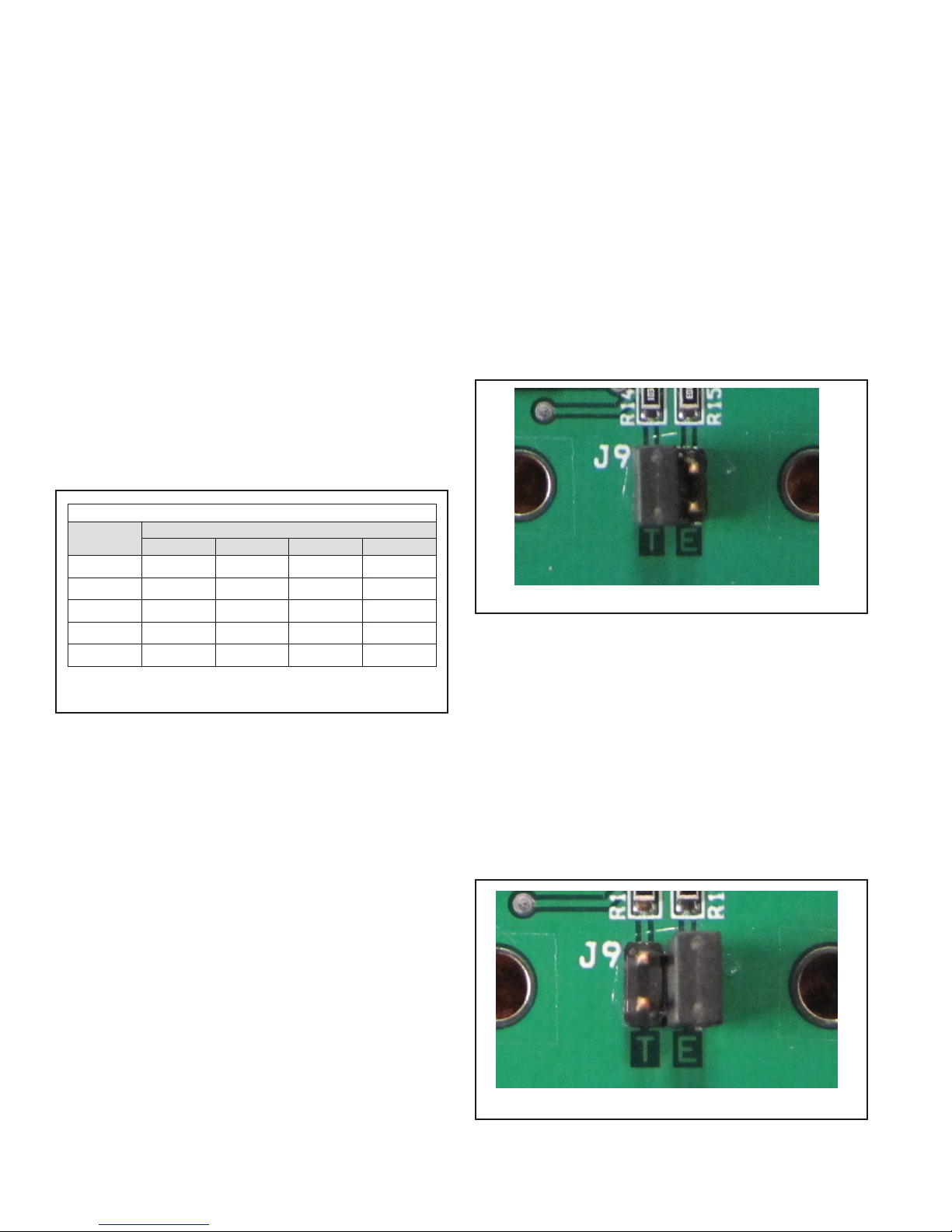
Temperature Control (See Figure 7)
The temperature mode of operation incorporates one
sensor located in the fresh air intake of the ERV. The Start
Stop Jog sequence is activated when the outside air
temperature is between 70°F and 40°F. The SSJ module
provides two potentiometers in order to adjust the Low and
High temperature range of the start stop jog sequence. To
adjust the High temperature range, place a Multimeter on
the COM and HIGH test points. Use a screw driver to
adjust the potentiometer to the desired VDC representing
the temperature. The Low temperature range is adjusted
by placing a Multimeter on the COM and LOW test points
with the adjustment of the potentiometer to the desired
VDC representing temperature. The VDC can be
calculated for a desired temperature using the following
formula: VDC = 0.1429 x (Temperature) - 5.7143.
Figure 7
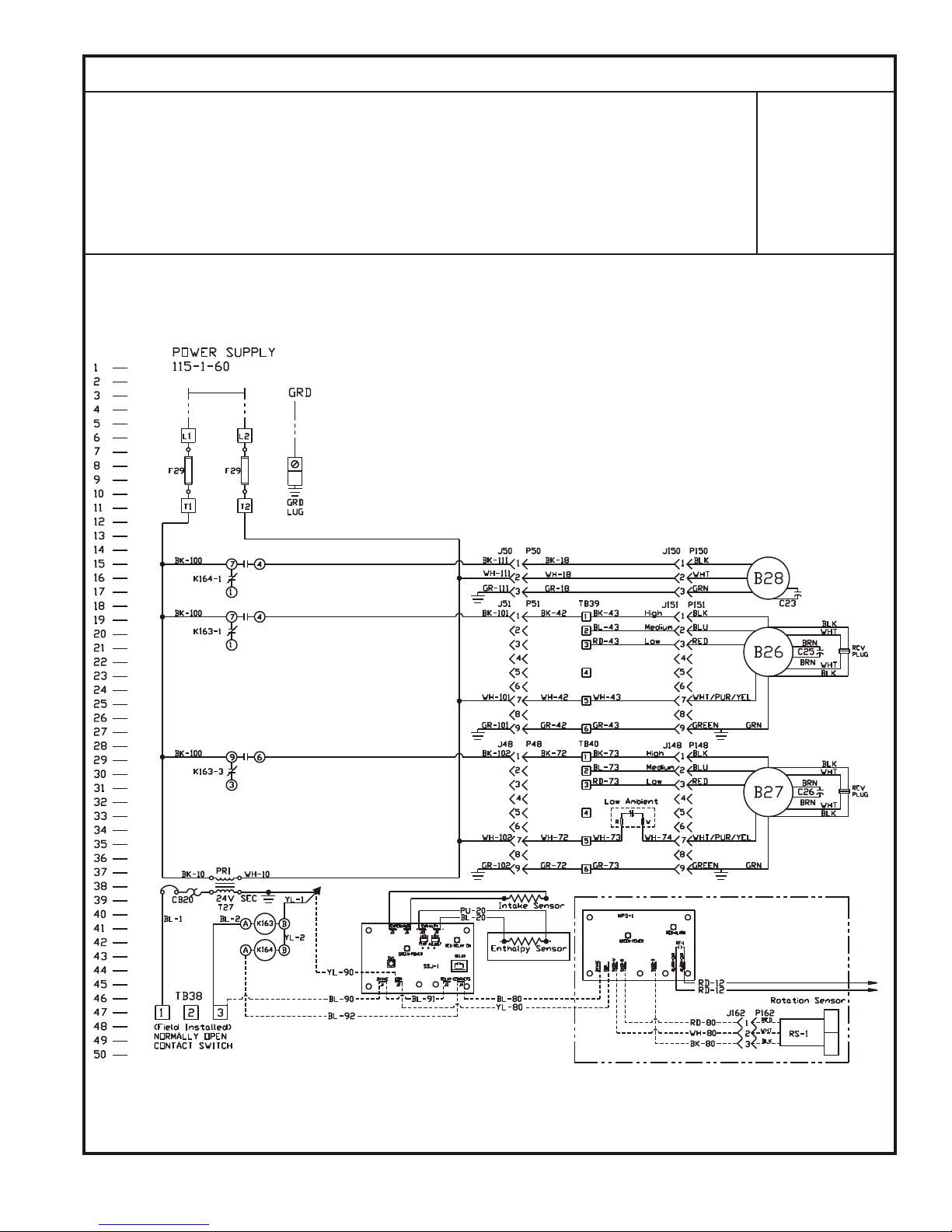
Enthalpy Control (See Figure 8)
The enthalpy mode of operation incorporates one enthalpy
sensor located in the fresh air intake of the ERV. The SSJ
module compares the outdoor enthalpy to a preselected
set point. The value of the set point can be identified on a
psychometric chart with the standard control curves as A,
B, C or D. The set point can be selected as an aggressive
set point A for higher levels of free cooling or a
conservative set point D for lower levels of free cooling.
The Enthalpy sensor provides a 4-20 mA (0-100%) signal
proportional to the selected control curve A, B, C, or D. The
SSJ module begins the start stop jog sequence when the
Enthalpy sensor reports 60%. The Enthalpy 60% setpoint
for each control curve is detailed in the following table:
Climate Smart [Patent Pending]
There are three modes of control strategies available.
Temperature, Single Enthalpy, or Enthalpy and
Temperature control.
Mode of Operation
The mode of operation is selected with the adjustment of a
jumper. The jumper is located at the lower center position
Figure 8
PAGE 4
Page 5

Enthalpy and Temperature (See Figure 9)
The combination mode of operation will activate the Start
Stop Jog sequence when the Enthalpy meets the control
curve setpoint and the outside air temperature is between
the Low and High temperature setpoint.
Figure 6
LED and Test Switch
There is a +5V LED indicating the module is wired and
powered properly. If the LED is not illuminated check the
wiring and power supply. The SSJ LED indicates when the
SSJ module has entered the start stop jog sequence. The
RELAY LED illuminates when the relay is activated cutting
power to the relay contacts.
The pushbutton on the module is used to test the relay.
When the pushbutton is activated the LED under the
button illuminates. The LED indicates test mode of the
relay is operating. The SSJ sequence will not operate while
the module is test mode.
Re cov ery Wheel Mode
On a call for operation the MV media will rotate between
intake air and exhaust air streams. Both the intake air
blower and exhaust air blowers will also be operating to
overcome the air resistance of the MV media.
X - Sys tem Check
1. Disconnect MV main power.
2. Remove control access panel and apply jumper to low
voltage terminal strip at “1” and “3”.
3. Restore power to unit. Observe MV drive motor for
wheel and both blowers are running.
4. Verify that the MV blower motors are set to “high”
speed for correct speed and operation.
A - Blower Speed Ad just ment
Blower speed selection is accomplished by changing the
speed selection switch on terminal strip in control box.
Both fresh air and exhaust air blowers are direct drive
multi-tap motors. Both blowers are factory set at “high”
speed for maximum airflow. To determine air flow setting,
external static pressure readings will need to be read
across the MV.
B - Air Bal anc ing Ad just ment
1. Remove plastic plugs in door panels(4 total).
2. With a manometer measure pressure drop [inches of
water column] across left half of MV(top and bottom
holes in door panel). Unit CFM is determined then by
referring to Table #2.
3. Repeat the same process for the right half of MV.
4. Place plastic plugs back in to door panels.
XI - Main te nance
1. All motors use prelubricated sealed bearings; no
further lubrication is necessary.
2. Make visual inspection of filters, motor assemblies
and MV rotating bearings during routine maintenance.
3. Filters should be checked periodically and cleaned
when necessary. Filter is located in front of MV unit
and before blower cabinet.
4. MV segment is positioned on a shaft extended from
middle support bar. Annual inspection of the self
cleaning wheel is recommended. With power
disconnected, remove MV access panels and unplug
[J150 & P150] (Refer to wiring diagram in this
instruction manual). Then remove wheel cassette
from cabinet by sliding assembly out of support tracks
Ex ter nal Static Pres sure
CFM
Ex ter nal Static Pres sure
CFM
Ex ter nal Static Pres sure 0.0 0.1 0.2 0.3 0.4 0.5 0.6 0.7 0.8 0.9 1
CFM
Low 498 479 459 435 411 384 347 307 263 218 175
High 592 565 530 496 463 431 398 356 311 262 218
Low 656 640 625 609 590 570 552 538 511 477 440
Me dium 729 708 690 671 649 627 605 582 560 530 495
High 783 765 740 721 700 678 650 622 598 580 560
Low 823 822 821 819 808 790 778 762 755 738 718
Me dium 997 992 985 975 960 940 928 905 884 872 850
High 1162 1145 1130 1104 1095 1090 1068 1047 1020 998 967
0.0
0.0
C25 / MV250 Cab i net
0.1 0.2 0.3 0.4 0.5 0.6 0.7 0.8 0.9 1.0
C45 / MV450 Cab i net
0.1 0.2 0.3 0.4 0.5 0.6 0.7 0.8 0.9 1
C75 / MV750 Cab i net
Table #2
PAGE 5
Page 6

in center of unit. Discoloration and staining of wheel
segment does not affect its performance. Only
excessive buildup of foreign material need be
removed. If the segment appears excessively dirty, it
should be cleaned to ensure maximum operating
efficiency. Thoroughly spray plastic surface with
household cleaner such as Fantastic® or equivalent or
middle detergent and gently rinse with warm water
using a soft brush to remove heavier accumulation.
Shake excess water from segment and replace in
reverse of removal instructions.
A - Wheel Removal (See Figure 10)
1. Remove Filter Access panel to expose wheel.
2. Disconnect wheel electrical harness.
3. Carefully slide the wheel outwards.
WHEEL
WHEEL ELEC TRI CAL HARNESS
FIL TER AC CESS PANEL
Figure 10
B - Filter Removal (See Figure 11)
1. Remove the Filter Access panel to expose filters.
2. Remove the filter pushers.
3. Slide filters outwards.
TERMINAL BLOCK
CONTROL BOX
Figure 12
XII - War ranty
RRS Man u fac tured Parts
In the event that defects in workmanship or materials
originate in any part manufactured by RRS, FOB point of
manufactured, we guarantee to repair or replace that part,
within three (3) months of the shipment date.
Other Sup plied Parts
Additionally, RRS guarantees to replace standard
components purchased new from a RRS vendor, (motors,
controls, etc.) that may be found defective, within twelve
(12) months of the installation date. The components
warranty, however, excludes service call charges and
labor cost for replacing or adjusting the defective part.
Lim i ta tion Of War ran ties
Misapplication, destruction, negligence or alteration
constitute the warranty and/or the components warranty of
RRS products and/or parts, null and void. This warranty is
provided in lieu of all other written, stated or implied
warranties.
FILTER
FIL TER PUSHER
FIL TER AC CESS PANEL
Figure 11
C - Control Box Location (See Figure 12)
The control box is located on the bottom left hand corners
of the MV when the Filter Access Panel is removed.
PAGE 6
Page 7

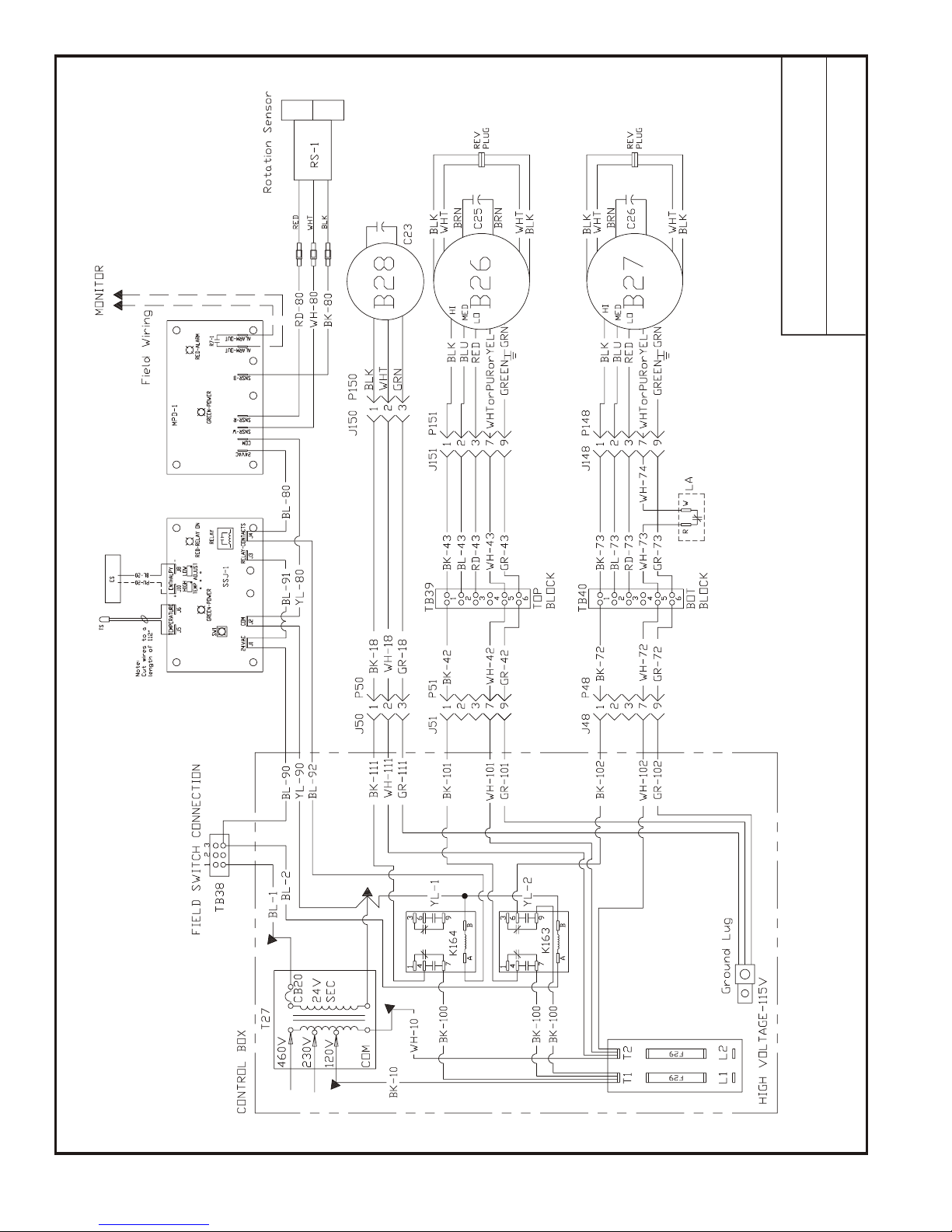
C25/MV250 UNIT SCHE MATIC DIAGRAM
B26 Mo tor, Ex haust Air
B27 Mo tor, Fresh Air
B28 Mo tor, Desiccant Wheel
C23 Ca pac i tor, W heel Mo tor
C25 Ca pac i tor, Mo tor Ex haust Air
C26 Ca pac i tor, Mo tor Fresh Air
CB20 Cir cuit Breaker, Trans former
ES Sen sor, Enthalpy
F29 Fuse
J48 Jack, Con trol Box (Fresh Air)
J50 Jack, Con trol Box (Wheel)
COM PO NENT CODE
J51 Jack, Con trol Box (Ex haust Air)
J148 Jack, Fresh Air Mo tor Har ness
J150 Jack, Wheel Mo tor Har ness
J151 Jack, Ex haust Air Mo tor Har ness
K163 Re lay, Mo tors
K164 Re lay, Wheel
LA Switch, Low Ambient
MPD-
Board, Rotation
1
P48 Plug, Con trol Box (Fresh Air)
P50 Plug, Con trol Box (Wheel)
P51 Plug, Con trol Box (Ex haust Air)
P148 Plug, Fresh Air Mo tor
P150 Plug, Wheel Mo tor
P151 Plug, Ex haust Air Mo tor
RS-1 Sen sor, Rotation
S26 Switch, Low Am bi ent (Op tional)
SSJ-1 Board, Start-Stop-Jog
T27 Trans former, Step-down
TB38 Ter mi nal Block (Low Volt age)
TB39 Ter mi nal Block (High Volt age, Ex haust)
TB40 Ter mi nal Block (High Volt age, Fresh)
TS Sen sor, Temperature
WIRE COLOR
BK Black
BL Blue
GR Green
OR Orange
PU Violet
RD Red
WH Whit e
YL Yel low
MV75-2ERW
PAGE 7
Page 8

snoi tpO dellat snI yro tcaF /W ro ta li tneV iniM
10-Hx2052 C-10 :#tinU
)HP 1( V511
MARGAID GN IRIW TINU 052VM/52C
PAGE 8
Page 9
C45/MV450 / C75/MV750 UNIT SCHE MATIC DIAGRAM
B26 Mo tor, Ex haust Air
B27 Mo tor, Fresh Air
B28 Mo tor, Desiccant Wheel
C23 Ca pac i tor, W heel Mo tor
C25 Ca pac i tor, Mo tor Ex haust Air
C26 Ca pac i tor, Mo tor Fresh Air
CB20 Cir cuit Breaker, Trans former
ES Sen sor, Enthalpy
F29 Fuse
J48 Jack, Con trol Box (Fresh Air)
J50 Jack, Con trol Box (Wheel)
COM PO NENT CODE
J51 Jack, Con trol Box (Ex haust Air)
J148 Jack, Fresh Air Mo tor Har ness
J150 Jack, Wheel Mo tor Har ness
J151 Jack, Ex haust Air Mo tor Har ness
K163 Re lay, Mo tors
K164 Re lay, Wheel
LA Switch, Low Ambient
MPD-
Board, Rotation
1
P48 Plug, Con trol Box (Fresh Air)
P50 Plug, Con trol Box (Wheel)
P51 Plug, Con trol Box (Ex haust Air)
P148 Plug, Fresh Air Mo tor
P150 Plug, Wheel Mo tor
P151 Plug, Ex haust Air Mo tor
RS-1 Sen sor, Rotation
S26 Switch, Low Am bi ent (Op tional)
SSJ-1 Board, Start-Stop-Jog
T27 Trans former, Step-down
TB38 Ter mi nal Block (Low Volt age)
TB39 Ter mi nal Block (High Volt age, Ex haust)
TB40 Ter mi nal Block (High Volt age, Fresh)
TS Sen sor, Temperature
WIRE COLOR
BK Black
BL Blue
GR Green
OR Orange
PU Violet
RD Red
WH Whit e
YL Yel low
MV75-2ERW
PAGE 9
Page 10
snoi tpO dellat snI yro tcaF /W ro ta li tneV iniM
10-Hx2057C/54 C-10 :#tinU
)HP 1( V511
MARGAID GN IRIW TINU 057VM/57C / 054VM/54C
PAGE 10
Page 11

START UP INFORMATION SHEET
VOLTAGE - MV UNIT
In com ing Volt age L1-L2
Run ning Volt age L1-L2
Sec ond ary Volt age
AM PER AGE - MV MO TORS
In take Mo tor: Nom i nal HP Rated Amps Run ning Amps
Ex haust Mo tor: Nom i nal HP Rated Amps Run ning Amps
Wheel Mo tor: Nom i nal HP Rated Amps Run ning Amps
AIR FLOW
In take De sign CFM Pres sure Drop Cal cu lated CFM
Ex haust De sign CFM Pres sure Drop Cal cu lated CFM
Amb. db Temp Re turn Air db Temp* Tem pered Air db Temp*
Amb. wb Temp Re turn Air wb Temp* Tem pered Air wbTemp*
* Mea sure af ter 15 min utes of run time
IN STAL LA TION CHECK LIST
MV Model # Se rial #
Owner Owner Phone #
Owner Ad dress
In stall ing Con trac tor Start Up Me chanic
q Inspect the unit for transit damage and report any damage on the carrier’s freight bill.
q Check model number to insure it matches the job requirements.
q Install field accessories and unit adapter panels as required. Follow accessory and unit installation manuals.
q Verify field wiring, including the wiring to any accessories.
q Check all multi-tap transformers, to insure they are set to the proper incoming voltage.
q Verify blower wheels are centered. Realign if needed.
q Prior to energizing the unit, inspect all the electrical connections.
q Power the unit. Bump the motor relay to check rotation. If blower motor fans are running backwards,
de-energize power to the unit, then swap reversing plug on motors to change direction. Re-check.
q Perform all start up procedures outlined in the installation manual shipped with the unit.
q Fill in the Start Up Information as outlined on the opposite side of this sheet.
q Provide owner with information packet. Explain the thermostat and unit operation.
PAGE 11
 Loading...