

Page 1

Bulletin BZW05
BREEZEWAY
Wall Mounted Propeller Fans
Direct Drive and Belt Drive
Page 2
CERTIFIED RATINGS
PennBarry certifi es that the Breezeway
direct drive and belt drive models shown
on pages 12-13, and 18-39 are licensed to
bear the AMCA seal. The ratings shown are
based on tests and procedures performed
in accordance with AMCA publication 211
and AMCA publication 311 and comply with
the requirements of the AMCA Certifi ed
Ratings Program.
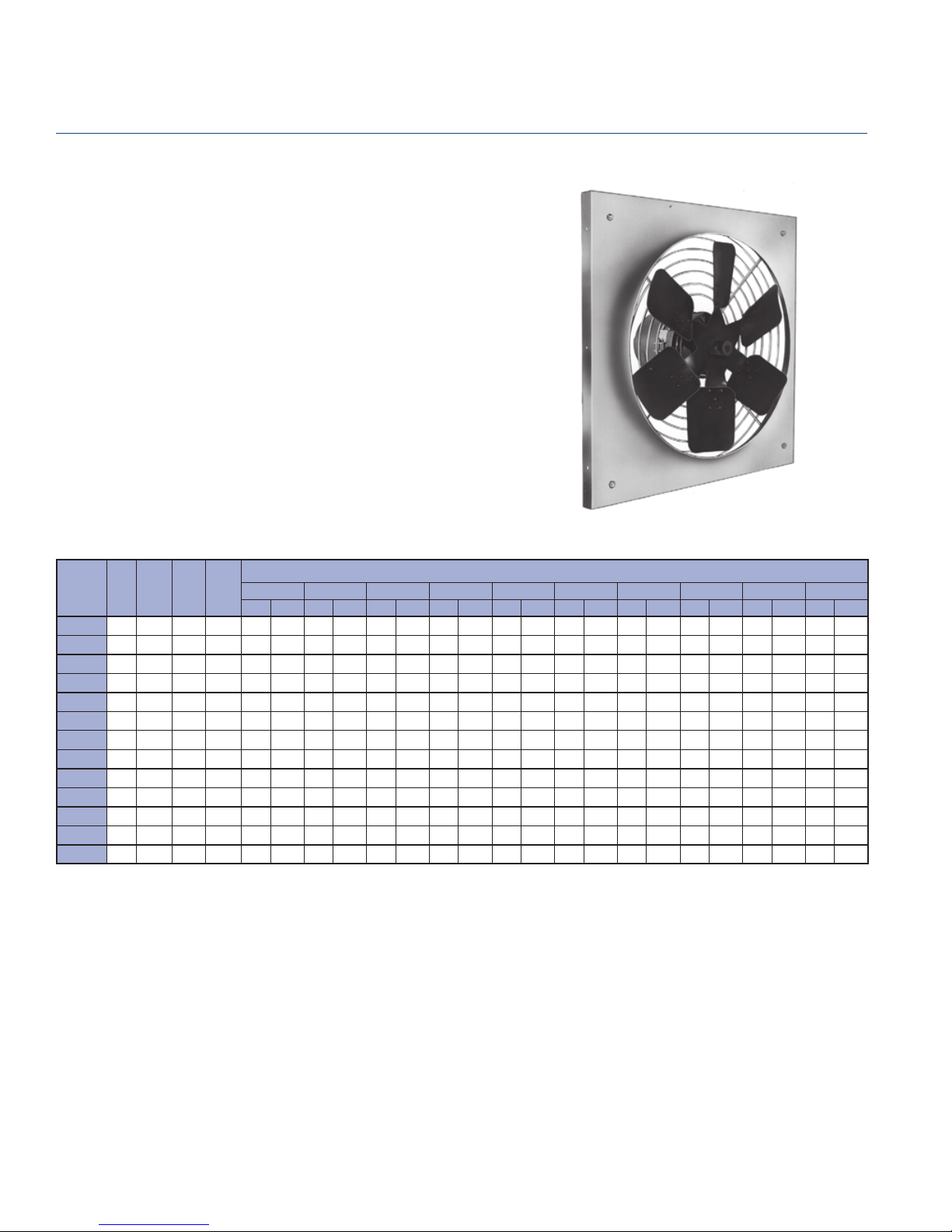
Breezeway Fan
Introduction
Table of Contents
Introduction . . . . . . . . . . . . . . . . . . . . . . . . . . . . . . . 1
General Information . . . . . . . . . . . . . . . . . . . . . . . . 2
Options and Accessories . . . . . . . . . . . . . . . . . . . . . 3
Motor Selection . . . . . . . . . . . . . . . . . . . . . . . . . . . 8
Direct Drive Dimensional Data . . . . . . . . . . . . . . . 11
UL and CSA Certifi cation
Breezeway fans (Models P, BLL, BHM, BHH
& BCH) carry the UL label, UL 705, (ZACT),
File #E28413.
Breezeway fans (Models P, BLL, BHM, BHH
& BCH) are also certifi ed by the Canadian
Standard Association (File #LR13309).
FANSIZER®
Product Selection Software
FanSizer software allows you to select the best centrifugal or
axial unit for your application. Input CFM and static pressure,
and FanSizer will make the optimum selection. It allows you to
complete job schedules which you can store, modify and print
in seconds. Features include: on-line help, on-screen product
drawings and dimensions, and complete text specifi cations.
In addition, you can convert job schedules to ASCII code for
use with other programs like word processing.
FANCAD®
Library of CAD Drawings
FanCad is a library of drawings for use with computer-aided
design (CAD) systems. FanCad’s pre-drawn details can save
hours of drafting time. Included are all popular PennBarry fans
and related items.
FanSizer and FanCad are registered trademarks.
Direct Drive Performance Data:
P Series . . . . . . . . . . . . . . . . . . . . . . . . . . . . . 12
Breezex (BX) . . . . . . . . . . . . . . . . . . . . . . . . . . 14
BC . . . . . . . . . . . . . . . . . . . . . . . . . . . . . . . . . . 15
Belt Drive Dimensional Data . . . . . . . . . . . . . . . . . 16
Belt Drive Performance Data:
BLL . . . . . . . . . . . . . . . . . . . . . . . . . . . . . . . . . 18
BHM/BHH . . . . . . . . . . . . . . . . . . . . . . . . . . . . 21
BCH . . . . . . . . . . . . . . . . . . . . . . . . . . . . . . . . 33
Sound Data Notes . . . . . . . . . . . . . . . . . . . . . . . . . 40
Engineering Notes . . . . . . . . . . . . . . . . . . . . . . . . . 41
Sample Specifi cations . . . . . . . . . . . . . . . . . . . . . 44
Limited Warranty . . . . . . . . . . . . . . . . . . . . . . . . . 45
Visit Our Web Site
Point your internet web browser to www.PennBarry.com for
up-to-the-minute information including:
• On-line catalog
• List of nearest PennBarry representatives
• What’s New
• HVAC “Hot Links”
Following publication of this catalog changes may have been made in standard equipment, options and the like that would not be included.
We reserve the right to make changes at any time, without notice, to models, specifi cations, options, availability, etc.
This bulletin illustrates the appearance of PennBarry products at the time of publication and we reserve the right to make changes
in design and construction at anytime without notice. Your local sales representative is the best source for current information.
©2005 PennBarry™ All rights reserved.
PENNBARRY
1
Page 3

General Information
Breezeway
The Breezeway propeller fan line provides a variety of solutions
to address the needs of wall mounted exhaust and ventilation
applications such as garages, factories, warehouses and other
relatively clean air applications.
Whether steel or cast aluminum, all propellers in the Breezeway
product line are statically and dynamically balanced to AMCA
Standard 204-96, Balance Quality and Vibration Levels for
Fans, to ensure quiet and reliable operation.
Breezeway fans allow one of the broadest motor selections
in the industry. All fans are fully assembled and test run prior
to shipping and belt drive models are pre-set to the specifi ed
RPM.
The following descriptions are provided to help guide
product selection to the most appropriate product for the
application.
DIRECT DRIVE
P Series – Designed for exhaust or
supply in light duty applications up to
6500 CFM and static pressures up to
5/8" W.G. Utilizes a stamped aluminum
propeller with steel hub, zinc-coated
wire guard/power assembly mounted
on RIS vibration isolators attached to
a steel venturi panel. Sizes 10" to 24"
are available.
Breezex (BX) – These reversible fans
are designed for applications where
supply and exhaust are required on a
fi eld-selectable basis. Available through
4600 CFM at static pressure up to 3/8"
W.G. Utilizes a stamped aluminum
propeller with steel hub, a fabricated
power assembly and steel venturi
panel. Motors are base-mounted
TE type. Explosion-proof motors are
available less reversing switch.
BELT DRIVE
BLL – An economical product designed
for applications through 14,000 CFM
at static pressures up to 1/2" W.G.
Sizes 24" to 36" are available. Utilizes
fabricated steel propeller, fabricated
steel power assembly and a steel
venturi panel.
BHM – Designed for medium duty
exhaust or supply applications with
volumes up to 34,000 CFM and static
pressures up to 3/4" W.G. Available
in sizes 24" to 48". Utilizes a higheffi ciency fabricated steel propeller,
galvanized power assembly, and a
fully developed venturi, integrally spun
into a galvanized panel.
BHH – A heavy duty series of propeller
fans designed for exhaust or supply
applications up to 58,000 CFM and
static pressures up to 1" W.G. The
BHH is a quiet and cost effective
solution to higher volume applications.
Utilizes a high-effi ciency fabricated
steel propeller, a robust galvanized
power assembly that can handle
high horsepower motors, and a fully
developed venturi integrally spun into
a galvanized panel. Available in sizes
24" to 60".
BCH – The most rugged wall propeller
fan in the Breezeway line, the BCH
utilizes a high effi ciency cast aluminum
air foil propeller, a fabricated steel
power assembly and a heavy gauge
venturi panel. Available in sizes 24"
to 60" with performances through
68,000 CFM and static pressures up
to 1" W.G.
BC Series – The BC picks up where
the P-Series and BX leave off, available
in 24" to 54" exhaust or supply
confi gurations through 43,000 CFM at
static pressures up to 3/4" W.G.
PENNBARRY
2
Safety Precautions for Installation
Since Breezeway fans contain rotating parts, PennBarry
recommends the following safety precautions be taken during
installation, operation and maintenance. Install FAN GUARDS
on all non-ducted fan installations to protect people working
around the fan and to protect the fan from foreign objects
coming into contact with moving parts. For proper and safe
operation, fan RPM should not exceed that recommended in
performance tables.
Page 4

PennBarry provides a wide variety of accessories for the Breezeway
propeller fan line. The components shown below can be mixed and
matched to suit the demands of the particular application.
Options and Accessories
Breezeway
WEATHERSHIELD
GUARD
WALL
SHUTTER
FRONT GUARD
(FOR USE WITH OR WITH-
OUT SHUTTER)
REAR GUARD
(FOR USE WHEN
WALL SLEEVE NOT USED)
WALL MOUNTING
SLEEVE GUARD
(REAR WALL SLEEVE GUARD
SHOWN, FRONT WALL SLEEVEG-
UARD AVAILABLE)
PANEL
FAN
WALL MOUNTING SLEEVE
WITH ADJUSTABLE
PERIMETER
MOUNTING ANGLE
Weathershield
Weathershields are designed to divert rain and snow from exhaust and supply wall openings.
They are designed to be surface mounted and can be installed in conjunction with wall shutters.
Guards are provided. Standard construction is galvanized steel, painted upon request. In order
to minimize shipping costs, the weathershield will be shipped knocked down for the BHM and
BHH products, unless factory assembly is specifi ed. Other models will be shipped factory
assembled.
Use the tables below to help with space planning and sizing guidelines. Please note the maximum
recommended intake (supply) CFM. This guideline will keep the intake CFM below 500 FPM.
If the intake CFM exceeds the recommended volume, use the next larger fan.
Dimensional Data
SIZE
Wo
A
B
C
15 3/4 17 3/4 23 1/2 25 27 1/2 33 1/4 28 3/4 34 3/4 40 3/4 46 3/4 55 61 67
15 1/4 17 1/4 23 24 1/2 27 32 3/4 28 1/4 34 1/4 40 1/4 46 1/4 54 1/4 60 1/4 66 1/4
18 3/8 19 11/16 23 3/4 24 13/16 26 9/16 30 1/2 27 3/8 31 3/4 36 5/8 41 45 3/4 49 5/8 54 5/8
12 3/8 13 1/8 15 1/2 16 1/8 17 1/4 19 1/2 17 5/8 20 1/4 23 3/8 25 7/8 28 3/8 31 34 1/4
Max. Rec.
Supply CFM
*Not Supply **BCH only
10 12 16 18 20 24 24 30 36 42 48** 54** 60**
10 12 16 18 20 24 24 30 36 42 48 54 60
806 1033 1837 2084 2531 3724 2771 4073 5625 7427 10219 12604 15240
P SERIES BLL*/BCH*/BC
WEATHERSHIELD
A
A
B
C
SIZE
Wo
A
B
C
Max. Rec.
Supply CFM
*BHH only
24 30 36 42 48 54* 60*
32 3/4 38 3/4 44 3/4 50 3/4 57 63 69
32 1/4 38 1/4 44 1/4 50 1/4 56 1/4 62 3/8 68 3/8
32 1/4 38 1/4 44 1/4 50 1/4 56 1/4 62 3/8 68 3/8
28 1/4 32 1/2 36 3/4 41 45 1/4 49 3/8 53 5/8
24 30 36 42 48 54 60
3611 5080 6799 8768 10986 13509 16233
BHM/BHH
PENNBARRY
3
Page 5

Options and Accessories
Breezeway
Rear and Front Guards
Protection is available for both the rear motor side (rear guard)
of the fan and the front face (front guard) of the fan. Both
B
A
A
B
assemblies include a sheet metal sleeve with an attached
guard. The rear guard is long enough to enclose the belt and
pulleys. The front guard is surface mounted and long enough
to enclose a wall shutter, if provided. The guard for either is
A
C
A
C
removable for maintenance. Standard shipment is knocked
down for BHM and BHH, or optionally available as factory
assembled. Shipment for other models is factory assembled
only. The guards on both conform to OSHA specifi cations.
FRONT GUARD REAR GUARD
Protection that conforms to OSHA regulations should be installed when fans are located within seven (7) feet of fl oor and/or
working level, or within reach of personnel. Review OSHA codes for specifi c details.
Dimensional Data
SIZE
A * * * * * * 28 3/16 34 3/16 40 3/16 46 3/16 54 1/4 60 1/4 66 1/4
B * * * * * * 13 1/2 16 1/2 16 1/2 20 1/2 25 25 25
SCREEN 1 PIECE 1 PIECE 1 PIECE 1 PIECE 1 PIECE 1 PIECE 1 PIECE 1 PIECE 1 PIECE 1 PIECE 1 PIECE 2 PIECES 2 PIECES
SQ.
C
*Motor side guard of concentric rings integral to unit. **BCH only
SIZE
SQ.
A
B FRONT 5555555
B REAR 20 20 20 22 22 27 27
C 32 3/8 38 3/8 44 3/8 50 3/8 56 3/8 62 1/2 68 1/2
SCREEN
*BHH only
10 12 16 18 20 24 24 30 36 42** 48** 54** 60**
15 1/2 17 1/2 23 1/4 24 3/4 27 1/4 33 28 5/8 34 5/8 40 5/8 46 5/8 54 3/4 60 3/4 66 3/4
24 30 36 42 48 54* 60*
32 3/4 38 3/4 44 1/4 50 1/4 56 1/4 62 3/8 68 3/8
1 PIECE 1 PIECE 1 PIECE 1 PIECE 1 PIECE 2 PIECES 2 PIECES
P SERIES BC/BLL/BCH
BHM/BHH
Wall Mounting Sleeve Guard / Weathershield Guard
These guards are supplied with the Weathershield and Wall Sleeve. They are fabricated 11 ga. galvanized wire “cage” suitable
for use for OSHA protection. (Note that guard may be attached to either front or rear of wall sleeve.)
Protection that conforms to OSHA regulations should be installed when fans are located within seven (7) feet of fl oor and/or
working level, or within reach of personnel. Review OSHA codes for specifi c details.
Dimensional Data
SIZE
SQ.
A
B 1-1/2 1-1/2 1-1/2 1-1/2 1-1/2 1-1/2 1-1/2
SCREEN
*BCH only
SIZE
SQ.
A
B 1-1/2 1-1/2 1-1/2 1-1/2 1-1/2 1-1/2 1-1/2
SCREEN
*BHH only
PENNBARRY
4
24 30 36 42* 48* 54* 60*
29 34-5/8 40-5/8 46-5/8 54-3/4 60-3/4 66-3/4
1 PIECE 1 PIECE 1 PIECE 1 PIECE 1 PIECE 2 PIECES 2 PIECES
24 30 36 42 48 54* 60*
32-3/8 38-3/8 44-3/8 50-3/8 56-3/8 62-1/2 68-1/2
1 PIECE 1 PIECE 1 PIECE 1 PIECE 1 PIECE 2 PIECES 2 PIECES
BC/BLL/BCH
BHM/BHH
A
A
B
Page 6

Options and Accessories
Breezeway
Wall Shutters
Type WSR recessed gravity shutters, the most
popular form of backdraft protection, open when
the fan starts and automatically close shut when
the fan stops. These shutters are used for exhaust
only and are enclosed within a heavy, steel frame
that protects the roll-formed steel blades. Each
blade pivots freely on nylon bearings. Blades
are interconnected with one or more tie-rods
for simultaneous operation. Consult factory for
surface mount shutters, if required.
Type EBR is the motorized version of the gravity
WSR. It includes all of the WSR features plus an
enclosed actuator motor for positive opening and
closing of the shutter. The motor is fi eld wired in
parallel with the fan. Allow a minimum 7" between
the fan and the shutter when motorized. Larger
actuators will be provided with a transformer for
460V.
Shutters required for supply applications are
provided as motorized center-pivot type (not
illustrated.) If standard top-pivot shutter is used
for supply applications, a fi eld supplied time delay
relay is strongly recommended.
Caution: When a Breezeway fan is selected
for a supply application, fan velocities greater
than 500 FPM can pull water into the structure.
We suggest that a PennBarry Weathershield be
selected in supply applications to help prevent
water penetration when high velocity conditions
cannot be avoided.
1-1/48"
AIR
FLOW
SQ.
C
RECESS MOUNTING
RECESS MOUNTING
(Specify front guard if required.)
EXTRUDED
VINYL
5"
TYPE WSR
3"
9"
TYPE EBR
3"
5"
SQ.
E
(BACK OF SHUTTER)
Legend:
1. Flanged Steel Frame
2. Self-Acting Steel Blades
3. Mounting Holes
4. Motor Mounting Assembly
SQ.
C
SQ.
E
11/2”
Dimensional Data
SIZE
SQ.
E
SQ.
C
No. of Panels
*BCH only.
SIZE
SQ.
E
SQ.
C
No. of Panels
*BHH only.
10 12 16 18 20 24 24 30 36 42* 48* 54* 60*
17 1/2 19 1/2 25 1/4 26 3/4 29 1/4 34 3/4 30 1/2 36 1/2 42 1/2 48 1/2 56 1/2 62 1/2 68 1/2
15 17 22 3/4 24 1/4 26 3/4 32 1/4 28 34 40 46 54 60 66
1111111122222
24 30 36 42 48 54* 60*
34 1/2 40 1/2 46 1/2 52 1/2 58 1/2 64 1/2 70 1/2
32 38 44 50 56 62 68
1122222
P SERIES BLL/BCH/BC
BHM/BHH
PENNBARRY
5
Page 7

Options and Accessories
Breezeway
Wall Sleeves
Wall Sleeves effectively add depth to the wall where the fan and several of its
accessories will be installed. This provides more fl exibility and convenience
to secure these parts, as well as protection and a neat appearance. Standard
construction is galvanized steel. Standard shipment is knocked down for BHM
and BHH, or optionally available as factory assembled. Shipment for other
models is factory assembled only. A guard is provided for either front or rear
installation.
Wo
C
SQ.
A
SQ.
MIN.
SQ.
E
Dimensional Data
SIZE
SQ.
Wo
SQ.
A
MIN.
C
D
SQ.
E
*BCH only
SIZE
SQ.
Wo
SQ.
A
MIN.
C
D
SQ.
E
*BHH only
FAN AND WALL SHUTTER SHOWN
FOR REFERENCE ONLY
ANGLE
SUPPORT
(BY OTHERS)
D
P SERIES BC/BLL/BCH
10 12 16 18 20 24 24 30 36 42* 48* 54* 60*
15 3/4 17 3/4 23 1/2 25 27 1/2 33 28 3/4 34 3/4 40 3/4 46 3/4 55 61 67
15 1/4 17 1/4 23 24 1/2 27 32 1/2 28 1/4 34 1/4 40 1/4 46 1/4 54 1/4 60 1/4 66 1/4
444455666677 1/27 1/2
18 3/4 18 3/4 22 3/4 23 24 3/4 30 3/4 30 3/4 35 38 44 47 1/2 48 48
17 5/8 19 5/8 25 3/8 26 7/8 29 3/8 34 7/8 30 5/8 36 5/8 42 5/8 48 5/8 56 5/8 62 5/8 68 5/8
BHM/BHH
24 30 36 42 48 54* 60*
32 3/4 38 3/4 44 3/4 50 3/4 57 63 69
32 1/4 38 1/4 44 1/4 50 1/4 56 1/4 62 3/8 68 3/8
6666777
36 39 41 41 41 48 48
34 3/8 40 3/8 46 3/8 52 3/8 58 3/8 64 3/8 70 3/8
Breezex Accessories
BREEZEX
MODEL
NUMBER
BX12Q
BX14Q
BX16Q
BX16T
BX18Q
BX18T
BX20Q
BX20T
BX24Q
BX24T
Refer to appropriate drawings on pages 3, 4 and 5.
PENNBARRY
6
MOTOR OPERATED
SHUTTER
SQ.
C
15 18 15 1/8 15 1/8 14 11/16 12 1/2 15 1/4 17 7/8 12 3/8
15 18 16 5/8 16 5/8 16 3/16 12 1/2 16 1/4 19 12 3/4
19 22 19 3/8 19 3/8 18 15/16 12 1/2 19 20 13 7/8
21 24 21 3/8 21 3/8 21 15/16 12 1/2 21 22 3/8 14 1/2
22 3/4 25 3/4 23 3/8 23 3/8 22 15/16 12 1/2 23 23 1/4 15 1/2
26 3/4 29 3/4 27 3/8 27 3/8 26 15/16 13 1/2 27 26 1/8 17 1/4
SQ.
E
FRONT
GUARD
A
SQ.
REAR GUARD WEATHERSHIELD
SQ.
C
SQ.
A
BA
SQ.
BC
Page 8
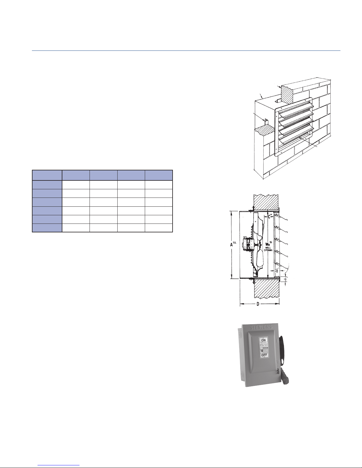
Breezeway P Series Slip-In Fan Pak
Provides a ventilation package in one convenient and compact
assembly. The Fan Pak incorporates the Breezeway Type P
direct drive fans with their integral back guards installed in a
galvanized steel sleeve with a self-acting shutter on the exterior
face. (A motorized shutter can be substituted for the standard
shutter when desired.)
A moveable angle frame is positioned on the perimeter of
the sleeve. This adjusts to the wall thickness. When properly
fastened it secures the assembly in the wall opening. Anchor
bolts, lag screws or other appropriate fasteners should be
used to fasten the unit to the inside and outside face of the
wall or mounting frame.
Options and Accessories
Galv. Steel Sleeve with Type P Direct
Drive Fan and Integral Rear Guard
Movable Permeter Angle Frame
(Adjusts to Wall Thickness)
Breezeway
Wall
Wall Shutter
(Self Acting)
MODEL Wo
P10 15 3/4 15 1/4 4 18 3/4
P12 17 3/4 17 1/4 4 14 3/4
P16 23 1/2 23 4 22 3/4
P18 25 24 1/2 4 23
P20 27 1/2 27 5 24 3/4
P24 33 1/4 32 1/2 5 24 3/4
SQ.
SQ.
A
MIN.
C
D
Paint and Coatings
In most cases, the standard epoxy fi nish is suffi cient to provide
years of attractive life to your propeller fan. For those cases
where corrosive fumes are encountered or where special
protective fi nishes are otherwise needed, the Breezeway can
be provided with special coatings. Accessories for BHM/BHH
will be provided assembled, not knocked down, if painting is
specifi ed.
Disconnect Switches
Safety disconnect switches are required under the National
Electric Code whenever an electric power source is controlled
from a switch or panel that is out of sight of the operated
equipment. Factory wiring is not available for explosion proof
motors.
PENNBARRY
7
Page 9

Motor Selection
Breezeway
After choosing a fan model, it is important to review the motor
availability charts to verify that the desired voltage, phase and
motor enclosure is available. Some factors affecting motor
selection are discussed below.
Electric Power Considerations
First, determine the nature of the electric power feeding
the motor. Is it single phase or three phase power? Next,
determine the required line voltage. Is it 115V, 230V, 460V?
Then determine the frequency. Is it 60 Hz or 50 Hz?
Environmental Considerations
Most clean air fan applications utilize Open Drip-Proof
(ODP) motors. Hazardous environments require Explosion
Proof motors. Explosion Proof motors are rated for NEMA
Class 1, Group D, Div. 1 and Class II, Groups F and G,
Div. 1 applications. Dirty environments require TE motors.
Ambient temperatures above (50 deg C) require special
motor construction. When in doubt, consult your PennBarry
representative or the factory for application assistance.
Caution: Hazardous environments also require special
fan construction suitable for the conditions.
Fixed Speed Motor Control
Two-speed motors, used in conjunction with external switches
or sensors (gas concentration, odor, temperature, etc.), are
used to adjust the airfl ow through the ventilator by changing
from one fi xed speed to another. Typical two-speed motor
designation is 2-speed, 2-winding (1800/1200 Nominal RPM).
2-speed, 1-winding motors (1800/900 Nominal RPM) are
available for 3-phase power only. Dual voltage motors are not
available in a 2-speed confi guration.
Variable Speed Motor Control
PennBarry Lek-Trol™ solid state controllers are an economical
way to reduce the high speed of selected P Series motors
by as much as 50%. Check the Lek-Trol™ availability table
on the following page to verify suitability for the fan model
selected.
Motors suitable for use with fi eld supplied Frequency Inverters
can be supplied for BLL, BHM, BHH, BC and BCH models.
Contact your PennBarry representative.
High-Effi ciency Motors
Motors that comply with the requirements of the energy Policy
Act of 1992 are provided when the required voltage, speed
and enclosure are applicable.
Direct Drive Motor Availability Charts
The following charts list the motors available for each of the direct drive fan models.
BC Direct Drive Motor Availability
MODEL HP
BC24W1 1/6 X YES YES NA YES NA NA NA NA
BC24W2 1/3 X YES NA NA YES YES NA NA NA
BC24T1 1/2 X YES YES YES YES YES YES NA NA
BC24T2 1 X YES YES YES YES YES YES YES YES
BC24Q 1 1/2 X YES YES YES YES YES YES YES YES
BC30W1 1/3 X YES NA NA YES YES NA NA NA
BC30W2 1/2 X YES NA NA YES YES NA NA NA
BC30W3 3/4 X NA NA NA YES YES NA NA NA
BC30T1 1 X YES YES YES YES YES YES YES YES
BC30T2 1 1/2 X YES YES YES YES YES YES YES YES
BC30Q1 3 X YES YES YES YES YES YES YES YES
BC30Q2 5 X NA YES YES YES YES YES YES YES
BC36W1 1 X NA NA NA YES YES NA NA NA
BC36W2 1 1/2 X NA NA NA YES YES NA NA NA
BC36T1 3 X YES YES NA YES YES YES YES YES
BC36Q 7 1/2 X NA YES NA YES YES YES YES YES
BC42W1 2 X NA NA NA YES YES NA NA NA
BC42W2 5 X NA NA NA YES YES YES NA NA
BC42T 5 X NA YES NA YES YES NA YES YES
BC48W1 3 X NA NA NA YES YES YES NA NA
BC48W2 5 X NA NA NA YES YES NA NA NA
BC48W3 7 1/2 X NA NA NA YES YES NA NA NA
BC48T1 7 1/2 X NA NA NA YES YES NA YES YES
BC48T2 10 X NA NA NA YES YES YES YES YES
BC54M 5 X NA NA NA YES YES YES NA NA
BC54W 10 X NA NA NA YES YES NA NA NA
690 M860W1140T1725QOPEN
RPM SINGLE PHASE THREE PHASE
115/230V
TE EXP OPEN TE EXP 2S1W 2S2W
PENNBARRY
8
Page 10
P Series Direct Drive Motor Availability
and Lek-Trol™ Controller Availability
MODEL
P10VA 1/30 X YES LT30 NA NA
P10RA 1/12 X YES LT30 USE TE LT35 YES (2) LT30/35*
P12VA 1/12 X YES LT30 NA NA
P12RA 1/4 X YES LT50 USE TE LT35 YES (2) LT30/35*
P16VA 1/3 X YES NA NA
P16SA 1/2 X YES LT50 NA NA
P16RA 1/2 X YES LT40 USE TE NA YES (2) NA
P16Q1A 3/4 X YES LT60 USE TE NA YES (2) NA
P18VA 1/2 X YES NA NA NA
P18RA 3/4 X YES NA NA NA
P20TA 3/4 X (1) USE TE NA USE TE NA YES (2) NA
P20SA 1 X YES NA YES NA NA
P24VA 3/4 X USE TE NA USE TE NA YES (2) NA
NOM
HP
(1) Nominal 1140 RPM. (2) 50/60 Hz. (3) 60 Hz.
NOMINAL RPM 115/1/60 ODP 230/1/60 ODP TE 115/200/240/1
1050 1300 1550 1650 AVAIL LEK-TROL AVAIL LEK-TROL AVAIL LEK-TROL
*LT30 - 115
*LT35 - 200/240
Breezex Direct Drive Motor Availability
MODEL
BX12Q
BX14Q XY Y Y N
BX16T XYY (B)YN
BX16Q 1/3 X Y Y Y Y
BX18T XYYYN
BX18Q XY Y Y Y
BX20T XYYYN
BX20Q 1/3 X Y Y Y Y
BX24T XYY (C)YY
BX24Q XY Y Y Y
NOMINAL
HP
1/6 X Y Y Y N
RPM SINGLE PHASE
1140 1725
TE (A),
115V only
EXPL. PROOF
115 or 230V
A. Use TE for ODP applications. B. Uses 1/4 HP C. Uses 1/2 HP
THREE PHASE,
230/460V
TE (A)
EXPL.
PROOF
Motor Selection
Breezeway
NEMA – Motor Frame Size
SINGLE PHASE 220V, 230V, 460V or 575V THREE PHASE
OPEN DRIP PROOF TE
HP
115 V 230 V 115/230
1/4
1/3 48/56 48/56 56 56 56 56 56 56 —
1/2 48/56 48/56 56 56 56 56 56 56 56
1 56 56 56 56 56 56 56 56 145T
1 1/2 56 56 145T 184T — 56 56 56 182T
2 145T 145T 182T 182T — 56/145T 145T 145T 182T
3 184T 184T 184T 215T — 145T 182T 182T 184T
5 — — — — — 184T 184T 184T 215T
7 1/2 — — — — — 213T 213T 213T 215T
10 — — — — — 215T 215T 215T 256T
15 — — — — — 254T 254T 254T 284T
20 — — — — — 256T 256T 256T 284T
48 58 58 48/56 48 48 48 48 —
56 56 56 56 56 56 56 56 56
On horsepowers less than 1 1/2, motor frame sizes may change due to variations in voltage, special
features and motor manufacturer. Motors shown are ball bearing, continuous duty and 1750 RPM or
1750/1140 RPM for two speed - two winding motors.
EXPL
PROOF
2 SPEED
2 WDG
OPEN
DRIP PRF
This chart lists the NEMA frame sizes for
EXPL
PROOF
2 SPEED
2 WDG
TE
each combination of HP, phase, voltage,
enclosure and speed confi guration. Verify
the NEMA frame size for the desired motor
and compare to the maximum motor frame
size listed on the individual fan data page in
this brochure.
PENNBARRY
9
Page 11

Motor Selection
Nominal Ampere Ratings
Single Phase
HP 115V 208V 230V
1/6 4.4 2.4 2.2
1/4 5.8 3.2 2.9
1/3 7.2 4 3.6
1/2 9.8 5.4 4.9
3/4 13.8 7.6 6.9
1 16 8.8 8
The above values of full-load currents are for motors running
at usual speeds and motors with normal torque characteristics.
Motors built for especially low speeds or high torques may
have higher full-load currents, and multi-speed motors will
have full-load current varying with speed, in which case the
nameplate current ratings shall be used.
The voltages listed are rated motor voltages. The currents
listed shall be permitted for system voltage ranges of 110 to
120 and 230 to 240 volts.
The table data shown above is from the NEC 2005 edition,
table 430-148.
Three Phase
HP 208V 230V 460V
1/2 2.4 2.2 1.1
3/4 3.5 3.2 1.6
1 4.6 4.2 2.1
1 1/2 6.6 6 3
2 7.5 6.8 3.4
3 10.6 9.6 4.8
5 16.7 15.2 7.6
7 1/2 24.2 22 11
10 30.8 28 14
15 46.2 42 21
20 59.4 54 27
25 74.8 68 34
The above values of full-load currents are typical for motors
running at speeds usual for belted motors and motors with
normal torque characteristics. Motors built for low speeds
(1200 RPM or less) or high torques may require more running
current, and multi-speed motors will have full-load current
varying with speed, in which case the nameplate current
ratings shall be used.
The voltages listed are rated motor voltages. The currents
listed shall be permitted for system voltage ranges of 230 to
240 and 440 to 480 volts.
The table data shown above is from the NEC 2005 edition,
table 430-150.
The amperages given here are approximate values only and represent averages compiled from the tables of leading motor
manufacturers. Overload relay heaters should not be selected on the basis of these tables only. Heaters must be selected in
accordance with the actual motor current as shown on the nameplate. It is also important that ambient temperatures of the
area in which the motor control is located be taken into consideration when making heater selections. Ambient compensated
overload relays are available for abnormal temperature conditions.
PENNBARRY
10
Page 12
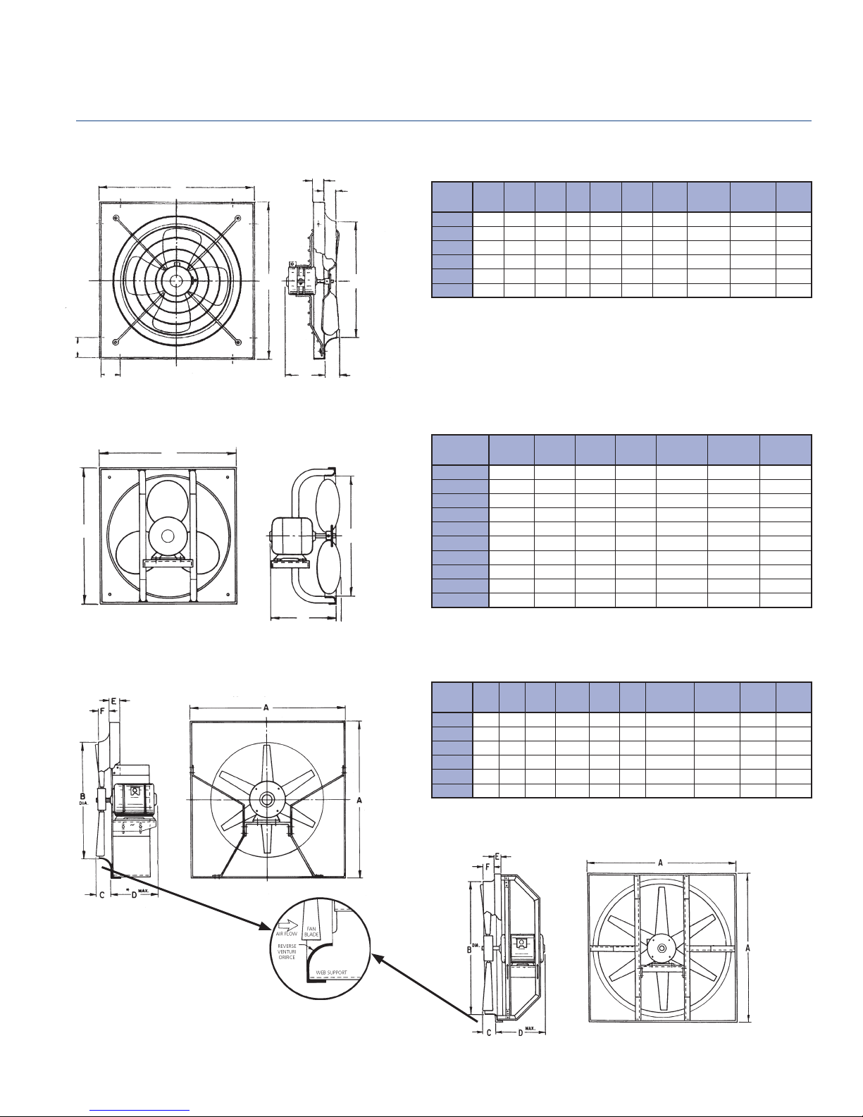
Direct Drive Dimensional Data
Breezeway
TYPE P
H
H
BREEZEX BX
SQ.
A
Dimensional Data
MAX.
E
F
DIA.
B
MODEL A B
P10
P12 17 12 1/4 3 1/4 1 1 7 1/2 1 7/8 17 3/4 14 18
P16 22 3/4 16 3/4 3 3/4 1 2 1/4 11 1/4 2 7/8 23 3/4 30 18
P18 24 1/4 18 3/4 3 3/4 1 2 9 1/8 3 5/8 25 40 18
P20 26 3/4 20 7/8 3 3/4 1 1 3/4 12 1/2 3 1/4 27 1/2 50 18
P24 32 1/4 25 4 1/4 2 2 3/8 12 7/8 4 11/16 33 76 18
DIA.CMAX.
15 10 3/4 2 1/2 1 1 1/4 6 1/2 3/4 15 3/4 12 18
EFG
MAX.
H
WALL
OPENING
Wo
APPROX.
SHIP WT.
(LBS.)
PAN EL
GAUGE
All wire frames are 11 gauge.
C
G
MAX.
A
A
Dimensional Data
WALL
SQ.
A
DIA.
B
MAX.
C
MODEL A
BX12Q
BX14Q 16 1/2 14 3/4 12 17 1/4 25 16 10
BX16T 19 16 3/4 12 1/2 19 3/4 29 16 10
BX16Q 19 16 3/4 12 1/2 19 3/4 29 16 10
BX18T 21 18 3/4 12 1/2 21 3/4 33 16 10
BX18Q 21 18 3/4 12 3/4 21 3/4 33 16 10
BX20T 23 20 3/4 13 1/2 23 3/4 35 16 10
BX20Q 23 20 3/4 12 1/2 23 3/4 35 16 10
BX24T 27 24 3/4 13 1/2 27 3/4 43 16 10
BX24Q 27 24 3/4 13 1/8 27 3/4 43 16 10
SQ.
14 1/2 12 3/4 12 15 1/4 24 16 10
DIA.
C
MAX.
OPENING
B
Wo
APPROX.
SHIP WT.
(LBS.)
PAN EL
GAUGE
MOTOR
PLATE
GAUGE
BREEZEWAY BC
BC24-42
REVERSE VENTURI DETAIL
Dimensional Data
WALL
MODEL A B
BC24
BC30 34 31 4 1/2 2 5/8 3 16 34 3/4 100 16 12
BC36 40 37 5 3 4 3/4 16 40 3/4 180 14 10
BC42 46 43 5 3 13/16 3 1/2 18 46 3/4 260 14 10
BC48 54 49 5 2 3/4 3 1/2 23 54 3/4 310 14 10
BC54 60 55 5 3 5 24 60 3/4 340 14 10
DIA.CMAX.
28 25 4 1/2 3 1/8 3 15 28 3/4 80 16 12
EFD
MAX.
OPENING
Wo
APPROX.
SHIP WT.
BC48-54
(LBS.)
PAN EL
GAUGE
WEB
GAUGE
PENNBARRY
11
Page 13
Direct Drive Fan Data
Breezeway
P Series
Features:
• Exhaust or supply
• Continuous duty, PSC motors
• Zinc-coated wire guard designed to OSHA specifi cations
• Integral spun steel venturi with welded corners
• Statically and dynamically balanced, die-formed aluminum
propeller with steel hub
• Integral vibration isolators
• Wide variety of available motors (Check Motor Availability
Chart – Page 9)
Performance Data
FAN CAPACITY IN CUBIC FEET PER MINUTE (CFM)
RPM
TIP
SPEED
0.000" SP 0.100" SP 0.125" SP 0.150" SP 0.200" SP 0.250" SP 0.300" SP 0.375" SP 0.500" SP 0.625" SP
(FPM)
CFM SONES CFM SONES CFM SONES CFM SONES CFM SONES CFM SONES CFM SONES CFM SONES CFM SONES CFM SONES
MODEL HP
P10VA 1/30 80 1050 2749 753 4.6 531 7.5 457 7.9 385 7.2 239 6.7
P10RA 1/12 115 1550 4058 841 5.8 699 6.5 631 7.3 570 8.5 486 10.8 425 12.5 387 12.9 321 13.2
P12VA 1/12 147 1050 3299 1343 10.7 1177 9.5 1123 9.9 1057 10.5 874 11.1 689 10.1 433 10.0
P12RA 1/4 174 1550 4869 1489 10.3 1367 9.8 1326 10.1 1281 10.5 1160 11.7 1046 13.2 882 15.5 798 16.9 568 19.6 210 20
P16VA 1/3 463 1050 4398 2546 9.1 2088 8.8 1859 8.7 1699 8.6 1257 8.3
P16SA 1/2 550 1300 5445 3143 13.7 2933 14.0 2856 14.1 2758 14.3 2495 14.6 2244 15.0 1982 15.3 1671 15.4
P16RA 1/2 724 1550 6492 3555 14.0 3301 14.1 3256 14.1 3211 14.2 3102 14.5 2955 15.3 2736 16.9 2514 18.3 1979 20 1772 21
P16Q1A 3/4 962 1650 6911 3760 16.3 3557 16.6 3508 16.7 3459 16.7 3358 16.9 3256 17.1 3123 17.6 2864 18.9 2369 22 2032 24
P18VA 1/2 522 1050 4948 4210 15.2 3845 15.1 3768 15.1 3661 15.1 3370 15.3 3030 15.1 2719 13.6 2215 13.1
P18RA 3/4 1265 1550 7304 5233 20 4971 21 4971 21 4919 21 4787 22 4633 23 4383 25 4029 28 3547 35 3083 34
P20TA 3/4 815 1140 5969 4852 16.2 4449 16.4 4318 16.5 4185 16.7 3898 17.1 3570 17.7 3278 18.4 2717 20 1969 24 1200 25
P20SA 1 1415 1300 6807 6063 22 5786 22 5692 21 5597 21 5397 21 5149 21 4835 21 4466 21 3909 22 3121 23
P24VA 3/4 1117 1050 6597 6562 14.6 6210 14.6 6136 14.7 6063 14.7 5917 14.7 5758 14.9 5576 15.2 5249 15.8 4065 19.3 3654 21
Performance shown is for installation Type A: Free Inlet, Free Outlet. Speed (RPM) shown is nominal. Performance is based on actual speed of test. The sound
ratings shown are for loudness values in fan sones at 5’0” (1.5m) in a hemispherical free fi eld per AMCA Standard 301. Values shown are for Installation Type A:
free inlet fan sone levels. Performance ratings include the effect of backguard in the airstream. For models shown on this page, the AMCA Certifi ed Ratings Seal
applies to air and sound. For further information on sound classifi cation, see page 40. For accessories, see pages 3 thru 7.
MAX
WATTS
PENNBARRY
12
Page 14

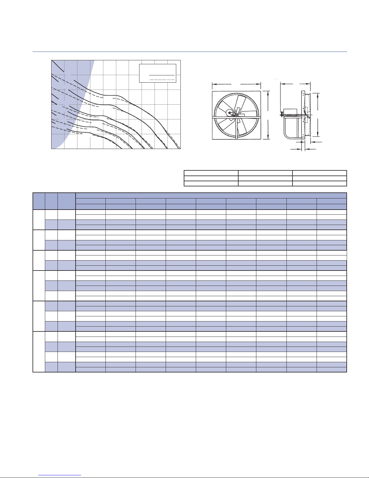
P Series Fan Curves
The fan curves illustrated here show the range of capacities
available for P series direct drive units. Each graph shows
the performance of several models at one particular nominal
speed. Fan curves provide a quick method for selecting a fan
unit based on design point requirements.
The direct drive performance chart on the previous page
provides the tabular data (CFM and static pressure) used to
plot the fan curves. In addition, horsepower, tip speed and
sones are tabulated. Since sound is normally an important
factor in the selection of a fan, an engineer will usually
Direct Drive Fan Data
Breezeway
want to select the “slowest” unit which meets CFM and SP
requirements.
Please refer to the Motor Selection section to make sure the
motor you select meets your electrical requirements.
Note: Breezeway fans are only one component of a total
system. As such, fan performance is directly affected by the
system. It is critical that system designers determine the actual
system loss to ensure that the actual fl ow is specifi ed in the
system design.
1050/1140 RPM
1.200
1.100
P24VA
P20TA
P18VA
P12VA
P10VA
0 1000 2000 3000 4000 5000 6000 7000
P16VA
AIR FLOW - CFM
STATIC PRESSURE - INCHES W.G.
1.000
0.900
0.800
0.700
0.600
0.500
0.400
0.300
0.200
0.100
0.000
1550 RPM
0.900
0.800
0.700
0.600
0.500
0.400
0.300
0.200
STATIC PRESSURE - INCHES W.G.
0.100
0.000
0 1000 2000 3000 4000 5000
P18RA
P16RA
P12RA
P10RA
AIR FLOW - CFM
1300 RPM
0.900
0.800
0.700
0.600
0.500
0.400
0.300
0.200
STATIC PRESSURE - INCHES W.G.
0.100
0.000
0 1000 2000 3000 4000 5000 6000
P16SA
P20SA
AIR FLOW - CFM
1650 RPM
1.400
1.300
1.200
1.100
1.000
0.900
0.800
0.700
0.600
0.500
0.400
0.300
STATIC PRESSURE - INCHES W.G.
0.200
0.100
0.000
0 1000 2000 3000 4000
P16Q1A
AIR FLOW - CFM
Do not select in dashed portion of curves. These regions are not shown in the tabular data.
PENNBARRY
13
Page 15

Direct Drive Fan Data
Breezeway
Breezex Reversible Fan
Features:
• Field reversible supply and exhaust
• Includes Reversing Switch (TE, 115V/1PH/60HZ only)
• Totally Enclosed (TE) Motor or Explosion Proof motors
available (Check Motor Availability Chart – Page 9)
• Integral Thermal Overload Protection
• Compact Panel Size
• Integral spun steel venturi with welded corners
• Statically and dynamically balanced, die-formed
aluminum propeller with steel hub
Performance Data (Supply Air)
FAN CAP. IN CUBIC FEET PER MIN. (CFM)
MODEL HP
BX12Q
BX14Q 1/6 14" 1725 6327 2000 1780 1580 1150 11.0
BX16T 1/6
BX16Q 1/3 1725 7231 3035 2760 2550 2250 13.0
BX18T 1/4
BX18Q 1/3 1725 8135 3500 3040 2275 1400 12.8
BX20T 1/4
BX20Q 1/3 1725 9039 3750 3440 3200 2560 14.0
BX24T 1/3
BX24Q
FAN
RPM
DIA.
1/6 12" 1725 5423 1400 1260 1050 805 4.0
1140 4779 2255 1885 1390 650 7.2
16"
1140 5376 3100 2670 2100 820 8.2
18"
1140 5974 3800 3160 2590 2240 9.3
20"
1140 7168 4720 4540 3855 3000 14.8
24"
1/2 1725 10847 4650 4400 3800 3480 20.0
TIP
SPEED
(FPM)
0.000" SP 0.125" SP 0.250" SP 0.375" SP
CFM CFM CFM CFM
SONES
@
.125"
Performance Data (Air Exhaust)
FAN CAP. IN CUBIC FEET PER MIN. (CFM)
MODEL HP
BX12Q 1/6 12" 1725 5423 1125 815 675 530 4.0
BX14Q 1/6 14" 1725 6327 1565 1395 1205 920 11.0
BX16T 1/6
BX16Q 1/3 1725 7231 2530 2345 1835 1430 13.0
BX18T 1/4
BX18Q 1/3 1725 8135 3000 2480 1980 1285 12.8
BX20T 1/4
BX20Q 1/3 1725 9039 3070 2835 2540 2245 14.0
BX24T 1/3
BX24Q 1/2 1725 10847 3555 3365 2905 2660 20.0
Performance shown is for installation Type A: Free inlet, Free outlet. Performance ratings do not include the effects
of appurtenances in the airstream. The sone ratings shown are loudness values in fan sones at 5'0" (1.5m) in a
hemispherical free fi eld calculated per AMCA standard 301. Values shown are for installation Type A: Free inlet fan
sone levels.
PENNBARRY
14
FAN
RPM
DIA.
1140 4779 1995 1520 1000 600 7.2
16"
1140 5376 2365 2040 1605 625 8.2
18"
1140 5974 2705 2265 2130 1835 9.3
20"
1140 7168 3610 3475 2945 2295 14.8
24"
TIP
SPEED
(FPM)
0.000" SP 0.125" SP 0.250" SP 0.375" SP
CFM CFM CFM CFM
SONES
@
.125"
Page 16

Direct Drive Fan Data
Breezeway
BC Cast Aluminum Propeller Fan
Features:
• Exhaust or supply
• Fabricated steel power assembly
• Statically and dynamically balanced, heavy duty cast aluminum
propeller with taper lock hub
• Integral spun steel venturi with welded corners
• TE, Explosion Proof and 2-speed motors available
(Check Motor Availability Chart – Page 8)
Performance Table
MODEL HP
BC24W1 1/2 24" 860 5404 3153 0.15 1988 0.16 1097 0.18 13.1
BC24W2 1/2 24" 860 5404 4444 0.40 2306 0.40 13.9
BC24T1 1/3 24" 1140 7163 4718 0.33 3957 036 3054 0.36 2273 0.38 18.9
BC24T2 1 24" 1140 7163 7025 0.95 5500 0.94 3800 0.94 2310 0.93 20.0
BC24Q 1 1/2 24" 1750 10996 7725 1.15 7380 1.19 6995 1.25 6500 1.28 5445 1.31 33.0
BC30W1 1/3 30" 860 6754 5641 0.29 3660 0.31 14.4
BC30W2 1/2 30" 860 6754 7624 0.41 6372 0.44 4084 0.43 1661 0.42 15.9
BC30W3 3/4 30" 860 6754 9034 0.64 7897 0.66 6430 0.67 3238 0.67 16.8
BC30T1 1 30" 1140 8954 10717 0.90 9884 0.97 8969 1.01 7767 1.04 3775 0.97 23.0
BC30T2 1 1/2 30" 1140 8954 12606 1.48 11771 1.50 10922 1.52 10022 1.54 7017 1.51 24.0
BC30Q1 3 30" 1750 13744 13643 2.28 12782 2.34 12157 2.39 11581 2.47 10164 2.59 36.0
BC30Q2 5 30" 1750 13744 17110 3.04 16625 3.19 16140 3.34 15600 3.45 14405 3.58 40.0
BC36W1 1 36" 860 8105 11099 0.88 9337 0.92 5963 0.95 2525 1.09 19.0
BC36W2 1 1/2 36" 860 8105 13248 1.25 11249 1.34 6912 1.28 21.0
BC36T1 3 36" 1140 10744 18526 2.85 17232 2.94 15820 3.06 13680 3.12 6422 2.99 31.0
BC36Q 7 1/2 36" 1750 16496 25430 7.13 24372 7.21 23476 7.30 22719 7.40 21040 7.58 48.0
BC42W1 2 42" 860 9456 20033 1.94 18114 2.01 16008 2.06 12931 2.14 24.0
BC42W2 5 42" 860 9456 23083 3.58 21837 3.70 20394 3.75 18525 3.76 13396 3.75 30.0
BC42T 5 42" 1140 12535 27644 4.38 26201 4.56 24750 4.67 23297 4.70 19880 4.87 35.0
BC48W1 3 48" 860 10807 25547 2.74 23003 2.85 20415 2.89 17287 2.90 8499 2.88 31.0
BC48W2 5 48" 860 10807 30186 3.98 27927 4.08 25555 4.17 22891 4.26 10571 4.47 34.0
BC48W3 7 1/2 48" 860 10807 33416 5.63 31631 5.73 29705 5.83 27640 5.90 22719 5.80 38.0
BC48T1 7 1/2 48" 1140 14326 35342 6.23 33384 6.44 31458 6.59 29638 6.67 25448 6.75 45.0
BC48T2 10 48" 1140 14326 41224 9.18 39622 9.31 37948 9.43 36214 9.56 32477 9.79 48.0
BC54M 5 54" 690 9755 34071 3.99 31816 4.04 29388 4.06 25491 4.12 12345 3.59 30.0
BC54W 10 54" 860 12158 43437 7.68 41645 7.76 39842 7.81 38091 7.83 32441 7.99 41.0
Performance shown is for installation Type A: Free inlet, Free outlet. Performance ratings do not include the effects of appurtenances in the airstream. The sone ratings
shown are loudness values in fan sones at 5’0” (1.5m) in a hemispherical free fi eld calculated per AMCA standard 301. Values shown are for installation Type A: Free
inlet fan sone levels.
FAN
DIA.
RPM
TIP
SPEED
(FPM)
0.125" SP 0.2509" SP 0.375" SP 0.500" SP 0.750" SP
CFM BHP CFM BHP CFM BHP CFM BHP CFM BHP
FAN CAPACITY IN CUBIC FEET PER MINUTE (CFM)
SONES
@
.125"
PENNBARRY
15
Page 17

Belt Drive Dimensional Data
Breezeway
MODEL BLL MODEL BCH
A
E
F
Dimensions
MODEL A B
DIA.
BLL24 28 25 16 3 3
BLL30 34 31 18 2 1/2 3
BLL36 40 37 20 3 4 3/4
MAX.
D
EF
MODEL BHM
A
D
A
MAX.
D
Dimensions
MODEL A B
DIA.
BCH24 28 25 16 3 3
BCH30 34 31 18 2 1/2 3
BCH36 40 37 20 3 4 3/4
BCH42 46 43 22 3 3/4 4 1/2
BCH48 54 49 25 2 3/4 4 3/4
BCH54 60 55 28 3 5
BCH60 66 61 28 2 3/4 6
MAX.
D
EF
MODEL BHH
A
D
DIA.
B
A
E
Dimensions Dimensions
MODEL A B
DIA.
BHM24B 32 25 1/2 26 3 5
BHM30B 38 31 1/2 26 3 5
BHM36B 44 37 1/2 28 3 5
BHM42B 50 43 1/2 28 3 5
BHM48B 56 49 1/2 28 2 5
PENNBARRY
16
MAX.
D
EF
B
F
EF
DIA.
A
E
MAX.
D
B
F
MODEL A B
BHH24B 32 25 1/2 26 3 5
BHH30B 38 31 1/2 26 3 5
BHH36B 44 37 1/2 28 3 5
BHH42B 50 43 1/2 28 3 5
BHH48B 56 49 1/2 28 2 5
BHH54B 62 55 1/2 36 3 5
BHH60B 68 61 1/2 36 3 5
Page 18

Belt Drive Fan Data
Breezeway
Performance Data
The belt drive models shown on the following pages have
sizes and capacities ranging from below 3,000 CFM to nearly
70,000 CFM, with static pressures from 0" to above 1 1/2".
All models are available in several different horsepower sizes
with a wide range of RPM.
The data provided for each belt drive model includes:
• Tabular performance data
• Fan curve
• Dimensional and physical data
Each curve graphically displays the range of capacities
available for each model, in most cases beyond the specifi cs
shown in the tabular data. The maximum performance afforded
by each horsepower is indicated by dashed lines and the RPM
is indicated by solid lines.
Refer to the appropriate Motor Availability chart (see Motor
Selection section) to confi rm available motors.
The belt drive models have graphs that show both shaded
and unshaded areas. Caution should be used when making
selections in the shaded areas.
The highest RPM shown for a specifi c horsepower in the
tabular data is the maximum speed that for any point along
the performance curve, the BHP will not exceed the available
horsepower.
Always consider belt drive losses into the BHP calculations
to ensure proper motor selection. PennBarry fan selection
software ALWAYS accounts for these losses. See ‘Belt Drive
Losses’ section, following, for an explanation of this topic.
Note: Breezeway fans are only one component of a total system. As such,
performance is directly affected by the system. It is critical that system designers
determine actual system losses to ensure that the actual fl ow is specifi ed in the
system range.
Belt Drive Losses
The AMCA Review Committee has developed the chart
shown below for the purpose of estimating belt drive losses.
To calculate total BHP (including drive losses): Find the BHP
of your operating point on the x-axis on the graph below.
Follow the vertical line to the lines indicating the range of drive
losses. Look at the y-axis on the left and fi nd the drive loss
percentage. Calculate the total BHP by adding the drive loss
to the operating point BHP. For BHP’s below 0.3, use 30%.
Caution: For totally enclosed, explosion proof, multi-speed
and all 1.0 Service Factor motors, fan BHP plus drive losses
should not exceed motor rated HP.
Note: FanSizer software incorporates a drive loss allowance when selecting a
required nominal horsepower.
Reprinted from AMCA publication 203, with the express written permission
from the Air Movement and Control Association, Inc., 30 West University Drive,
Arlington Heights, IL 60004-1983
30
20
15
10
8
6
Drive Loss
4
3
(% Motor Power Output)
2
1.5
1
0.3 0.4 0.6 0.8 1 2 3 4 6 8 10 20
Motor Power Output (BHP)
Range of drive loss for standard
belts. Higher fan speeds tend to
have higher losses than lower fan
speeds at the same horsepower.
Safety Precautions for Installation
Since Breezeway fans contain rotating parts, PennBarry
recommends the following safety precautions be taken
during installation, operation and maintenance. Install FAN
GUARDS on all non-ducted fan installations to protect
people working around the fan and to protect the fan from
foreign objects coming into contact with moving parts. For
proper and safe operation, fan RPM should not exceed
that recommended in performance tables. Installations that
result in EXCESSIVE VIBRATION are unacceptable.
PENNBARRY
17
Page 19
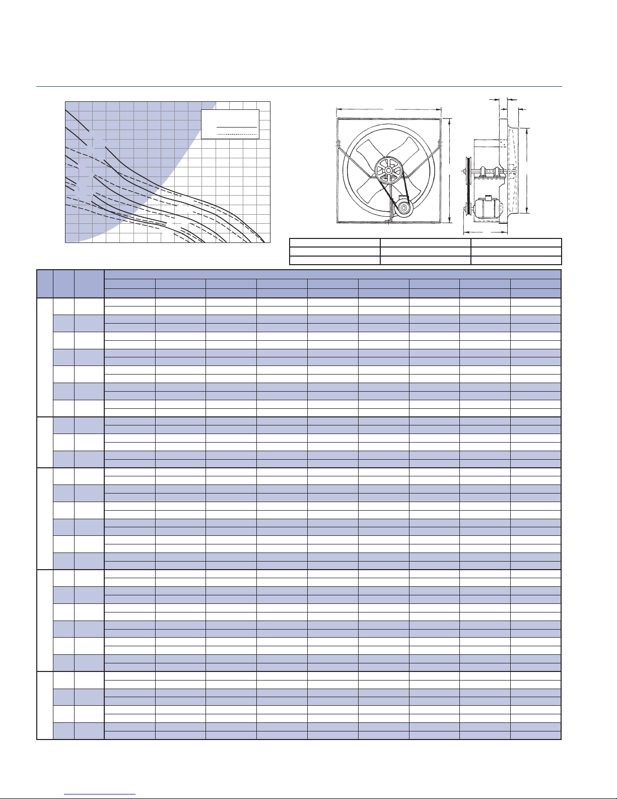
BLL 24 - Belt Drive Fan Data
Breezeway
1.500
1.400
1.300
1.200
1.100
1.000
0.900
0.800
0.700
0.600
0.500
0.400
0.300
STATIC PRESSURE - Inches W.G.
0.200
0.100
0.000
HP RPM
470 2953
530 3330
570 3581
1/4
630 3958
690 4335
720 4524
737 4631
750 4712
1/3
770 4838
792 4976
800 5027
825 5184
850 5341
1/2
875 5498
900 5655
912 5730
920 5781
945 5938
970 6095
3/4
995 6252
1020 6409
1048 6585
1060 6660
1090 6849
1
1110 6974
1124 7062
912 RPM
792 RPM
737 RPM
TIP
SPEED
(FPM)
1124 RPM
1048 RPM
1/3 HP
1/4 HP
AIR FLOW - CFM
0.000" SP 0.100" SP 0.125" SP 0.150" SP 0.200" SP 0.250" SP 0.300" SP 0.375" SP 0.500" SP
Sones BHP Sones BHP Sones BHP Sones BHP Sones BHP Sones BHP Sones BHP Sones BHP Sones BHP
3043 1541
6.3 0.07 6.3 0.08
3431 2313 1786
7.8 0.11 7.5 0.11 7.7 0.11
3690 2762 2312 1814
8.9 0.13 8.7 0.14 8.7 0.14 8.9 0.14
4078 3345 3009 2601
10.7 0.18 10.7 0.19 10.7 0.19 10.9 0.19
4467 3837 3620 3295 2527
14.0 0.23 13.4 0.24 13.3 0.25 13.2 0.25 13.5 0.25
4661 4078 3870 3618 2912
14.9 0.26 14.0 0.28 13.9 0.28 13.8 0.28 13.9 0.28
4771 4209 4010 3798 3120 2353
15.5 0.28 14.4 0.30 14.3 0.30 14.2 0.30 14.2 0.30 14.7 0.30
4855 4307 4116 3916 3277 2532
16.0 0.30 14.8 0.31 14.6 0.31 14.6 0.32 14.5 0.32 15.0 0.32
4985 4457 4278 4084 3510 2806
16.4 0.32 15.3 0.34 15.1 0.34 15.1 0.34 15.0 0.34 15.4 0.34
5127 4620 4456 4266 3753 3095
16.9 0.35 15.9 0.36 15.7 0.37 15.6 0.37 15.6 0.37 15.9 0.37
5179 4678 4520 4332 3840 3194 2502
17.1 0.36 16.1 0.37 15.9 0.38 15.8 0.38 15.8 0.39 16.1 0.38 16.6 0.39
5341 4855 4714 4537 4110 3500 2821
18.0 0.40 16.9 0.41 16.7 0.41 16.5 0.42 16.5 0.42 16.7 0.42 17.2 0.42
5503 5031 4901 4739 4375 3801 3161
19.6 0.43 18.3 0.45 17.9 0.45 17.5 0.46 17.3 0.46 17.4 0.46 17.8 0.46
5665 5206 5088 4940 4598 4081 3482
21 0.47 19.5 0.49 19.1 0.49 18.7 0.50 18.1 0.50 17.9 0.51 18.2 0.50
5827 5381 5270 5136 4806 4354 3789 2855
22 0.51 20 0.53 19.9 0.53 19.6 0.54 19.0 0.54 18.7 0.55 18.8 0.55 19.4 0.55
5904 5465 5355 5226 4906 4484 3934 3010
22 0.53 21 0.55 20 0.55 20 0.56 19.4 0.57 19.1 0.57 19.1 0.57 19.6 0.57
5956 5520 5411 5286 4972 4570 4031 3121
22 0.55 21 0.56 21 0.57 20 0.57 19.7 0.58 19.4 0.59 19.4 0.59 19.7 0.59
6118 5694 5587 5473 5177 4836 4321 3463
23 0.59 22 0.61 21 0.61 21 0.62 21 0.63 20 0.63 20 0.64 20 0.63
6280 5866 5763 5659 5380 5071 4596 3791
23 0.64 22 0.66 22 0.66 21 0.67 21 0.68 21 0.68 21 0.69 21 0.68
6442 6039 5938 5837 5581 5280 4868 4099
23 0.69 22 0.71 22 0.72 22 0.72 21 0.73 21 0.74 21 0.74 22 0.74
6604 6210 6112 6014 5781 5488 5136 4403
24 0.75 23 0.76 23 0.77 22 0.77 22 0.78 22 0.79 22 0.80 23 0.80
6785 6402 6306 6211 5996 5718 5432 4735 3405
25 0.81 24 0.83 24 0.83 24 0.84 23 0.85 23 0.86 23 0.86 24 0.87 24 0.87
6863 6484 6390 6295 6086 5816 5533 4869 3572
26 0.84 25 0.86 25 0.86 25 0.87 24 0.88 24 0.88 24 0.89 24 0.90 25 0.90
7057 6689 6597 6505 6311 6059 5784 5199 3982
29 0.91 28 0.93 27 0.94 27 0.94 26 0.95 25 0.96 25 0.97 25 0.98 26 0.97
7186 6825 6735 6644 6459 6221 5951 5416 4251
30 0.96 29 0.98 28 0.99 28 0.99 27 1.00 26 1.01 26 1.02 26 1.03 27 1.02
7277 6920 6831 6742 6563 6333 6066 5567 4426
31 1 29 1.02 29 1.02 29 1.03 28 1.04 27 1.05 27 1.06 27 1.07 27 1.07
3/4
1/2 HP
1 HP
HP
Do not select shaded area.
RPM
BHP
Performance shown is for installation Type A: Free Inlet, Free Outlet. Power rating (BHP) does not include drive losses. The sound ratings shown are for loudness values
in fan sones at 5'0" (1.5m) in a hemispherical free fi eld per AMCA standard 301. Values shown are for installation Type A: Free inlet fan sone levels. Performance ratings
do not include the effects of appurtenances in the airstream. For further information on sound classifi cation, see page 40. For accessories, see pages 3 thru 7.
PENNBARRY
18
28
Carbon Steel Panel = 16 gauge Wall Opening = 28 3/4 in.sq. Peak BHP = (RPM/941)^3
Galv. Steel Web = 12 gauge Wall Shutter ID = 28 in.sq. Max RPM = 1124 (1 HP)
Est. Shipping Weight = 95 lbs Max. Motor Frame Size = 56
FAN CAPACITY - CUBIC FEET PER MINUTE (CFM)
3
3
28
16
25
Page 20

0.800
0.700
0.600
0.500
0.400
0.300
0.200
STATIC PRESSURE - Inches W.G.
0.100
0.000
HP RPM
1/4
1/3
1/2
3/4
1
810 RPM
756 RPM
657 RPM
572 RPM
531 RPM
0
TIP
SPEED
(FPM)
420 3299
445 3495
460 3613
475 3731
490 3848
505 3966
520 4084
531 4170
540 4241
560 4398
572 4492
590 4634
610 4791
630 4948
645 5066
657 5160
660 5184
675 5301
695 5459
710 5576
730 5733
745 5851
756 5938
770 6048
790 6205
810 6362
1/2 HP
1/3 HP
1/4 HP
2000 4000 6000
AIR FLOW - CFM
0.000" SP 0.100" SP 0.125" SP 0.150" SP 0.200" SP 0.250" SP 0.300" SP 0.375" SP 0.500" SP
Sones BHP Sones BHP Sones BHP Sones BHP Sones BHP Sones BHP Sones BHP Sones BHP Sones BHP
5331 2695 1694 1139
8.2 0.13 8.6 0.13 9.3 0.14 9.9 0.15
5648 3612 2296 1581
9.0 0.16 8.9 0.16 9.4 0.16 10.1 0.17
5838 3952 2684 1854
9.5 0.17 9.4 0.18 9.7 0.17 10.3 0.18
6029 4265 3217 2212
10.0 0.19 9.8 0.20 10.1 0.19 10.6 0.20
6219 4565 3861 2576 1404
10.5 0.21 10.4 0.23 10.5 0.22 11.1 0.21 12.3 0.23
6409 4861 4211 2978 1665
11.1 0.23 10.9 0.25 11.1 0.24 11.6 0.23 12.8 0.25
6600 5127 4543 3508 1939
11.7 0.25 11.6 0.27 11.7 0.27 12.1 0.25 13.3 0.27
6739 5320 4767 4029 2138
12.2 0.26 12.0 0.29 12.2 0.29 12.4 0.27 13.7 0.28
6854 5476 4948 4306 2344 1431
12.5 0.28 12.3 0.30 12.5 0.30 12.7 0.29 13.7 0.29 14.9 0.31
7108 5819 5344 4765 2835 1782
13.3 0.31 13.2 0.34 13.3 0.34 13.5 0.33 14.2 0.32 15.4 0.34
7260 6007 5567 5025 3123 1995
13.8 0.33 13.7 0.36 13.8 0.36 14.0 0.36 14.8 0.33 15.9 0.36
7488 6286 5884 5389 3676 2324 1540
14.7 0.36 14.6 0.39 14.7 0.39 14.9 0.39 15.5 0.37 16.5 0.38 17.6 0.41
7742 6594 6231 5787 4504 2776 1893
15.6 0.40 15.6 0.43 15.6 0.44 15.8 0.43 16.3 0.41 17.2 0.42 18.3 0.44
7996 6899 6567 6158 5125 3264 2249
16.6 0.44 16.6 0.47 16.6 0.48 16.7 0.48 17.2 0.47 18.1 0.45 19.3 0.48
8186 7126 6801 6422 5466 3621 2522
17.4 0.47 17.4 0.50 17.4 0.51 17.5 0.51 17.9 0.51 18.9 0.48 20 0.50
8339 7299 6988 6632 5732 4020 2762 1675
18.1 0.50 18.0 0.53 18.0 0.54 18.0 0.54 18.5 0.54 19.5 0.51 21 0.53 22 0.57
8377 7341 7034 6684 5793 4123 2837 1729
18.3 0.51 18.2 0.53 18.1 0.54 18.2 0.55 18.7 0.55 19.6 0.51 21 0.53 22 0.57
8567 7551 7265 6943 6097 4704 3208 1994
19.1 0.54 19.0 0.57 19.0 0.58 19.0 0.59 19.5 0.59 20 0.56 21 0.56 23 0.60
8821 7830 7571 7270 6497 5509 3692 2341
19.5 0.59 19.5 0.62 19.6 0.63 19.6 0.64 19.9 0.64 20 0.62 22 0.60 23 0.64
9011 8038 7799 7504 6793 5862 4067 2618
19.8 0.63 19.9 0.66 19.9 0.67 19.9 0.68 20 0.69 21 0.67 22 0.63 23 0.68
9265 8314 8097 7814 7156 6308 4756 2980
20 0.69 20 0.72 20 0.72 20 0.74 21 0.75 21 0.74 22 0.70 23 0.72
9456 8520 8307 8044 7420 6621 5417 3348
21 0.73 21 0.76 21 0.77 21 0.78 21 0.79 21 0.79 22 0.75 23 0.76
9595 8671 8461 8212 7612 6844 5908 3619 1887
21 0.76 21 0.80 21 0.80 21 0.81 21 0.83 22 0.82 22 0.79 24 0.79 26 0.87
9773 8862 8656 8425 7854 7124 6239 3959 2136
21 0.80 21 0.84 22 0.85 22 0.85 22 0.87 22 0.87 22 0.85 24 0.82 26 0.90
10027 9134 8934 8728 8198 7520 6695 4436 2487
22 0.87 22 0.91 22 0.91 22 0.92 22 0.94 22 0.94 23 0.93 24 0.87 26 0.96
10281 9406 9210 9015 8512 7891 7129 5107 2842
23 0.94 22 0.98 23 0.98 23 0.99 23 1.01 23 1.02 23 1.01 24 0.95 27 1.01
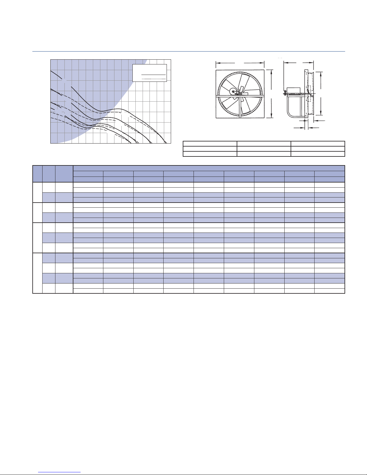
Performance shown is for installation Type A: Free Inlet, Free Outlet. Power rating (BHP) does not include drive losses. The sound ratings shown are for loudness values
in fan sones at 5'0" (1.5m) in a hemispherical free fi eld per AMCA standard 301. Values shown are for installation Type A: Free inlet fan sone levels. Performance ratings
do not include the effects of appurtenances in the airstream. For further information on sound classifi cation, see page 40. For accessories, see pages 3 thru 7.
Do not select shaded area.
RPM
BHP
1 H
P
3/4 HP
8000 10000
Belt Drive Fan Data - BLL 30
34
Carbon Steel Panel = 16 gauge Wall Opening = 34 3/4 in.sq. Peak BHP = (RPM/741)^3
Galv. Steel Web = 10 gauge Wall Shutter ID = 34 in.sq. Max RPM = 842 (1 HP)
Est. Shipping Weight = 110 lbs Max. Motor Frame Size = 56
FAN CAPACITY - CUBIC FEET PER MINUTE (CFM)
Breezeway
1
2
2
/
3
34
18
31
PENNBARRY
19
Page 21

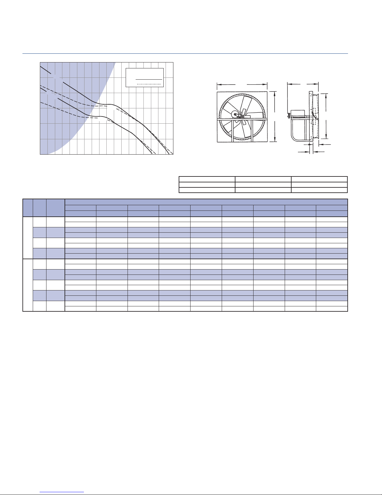
BLL 36 - Belt Drive Fan Data
Breezeway
0.700
1/2 HP
HP
3/4
HP
Do not select shaded area.
RPM
BHP
1 HP
0.600
0.500
0.400
0.300
0.200
STATIC PRESSURE - Inches W.G.
0.100
0.000
HP RPM
315 2944
325 3038
334 3122
344 3215
1/4
356 3327
366 3421
376 3514
381 3561
385 3598
390 3645
1/3
400 3738
410 3832
420 3925
430 4019
1/2
440 4112
460 4299
472 4411
482 4505
490 4580
500 4673
3/4
510 4767
525 4907
543 5075
550 5140
1
570 5327
582 5440
582 RPM
543 RPM
472 RPM
410 RPM
381 RPM
2000 4000 6000
0
TIP
SPEED
(FPM)
1/3
1/4 HP
8000 10000 12000 14000
AIR FLOW - CFM
0.000" SP 0.100" SP 0.125" SP 0.150" SP 0.200" SP 0.250" SP 0.300" SP 0.350" SP
Sones BHP Sones BHP Sones BHP Sones BHP Sones BHP Sones BHP Sones BHP Sones BHP
7455 2524
7.2 0.14 7.7 0.16
7691 2818
7.7 0.16 8.0 0.18
7904 3094
8.0 0.17 8.3 0.19
8141 3521 2577
8.3 0.19 8.6 0.20 8.9 0.22
8425 4075 2936
8.8 0.21 9.0 0.21 9.4 0.24
8662 4490 3228
9.2 0.22 9.3 0.22 9.8 0.25
8898 5239 3569 2798
9.7 0.24 9.5 0.24 10.1 0.26 10.4 0.29
9017 5770 3780 2949
9.9 0.25 9.6 0.26 10.3 0.27 10.6 0.29
9111 6038 3961 3068
10.1 0.26 9.7 0.27 10.4 0.27 10.7 0.30
9230 6268 4219 3216
10.4 0.27 9.9 0.28 10.5 0.28 10.9 0.31
9466 6722 4639 3509
10.9 0.29 10.2 0.31 10.9 0.30 11.4 0.33
9703 7170 5052 3829
11.4 0.31 10.6 0.33 11.3 0.31 11.8 0.34
9940 7619 5821 4252
12.0 0.34 10.9 0.36 11.6 0.34 12.2 0.36
10176 8003 6730 4739
12.6 0.36 11.5 0.38 11.8 0.38 12.6 0.37
10413 8309 7189 5158 3407
13.2 0.39 12.1 0.41 12.3 0.41 13.1 0.39 13.8 0.45
10886 8914 8089 6368 3997
14.5 0.44 13.3 0.47 13.2 0.47 13.9 0.44 15.0 0.50
11170 9272 8626 7417 4361
15.3 0.48 14.2 0.50 13.8 0.51 14.3 0.50 15.6 0.52
11407 9568 8985 7875 4785
16.0 0.51 14.9 0.53 14.6 0.54 14.9 0.53 16.1 0.55
11596 9804 9231 8238 5195 3751
16.5 0.54 15.4 0.56 15.1 0.57 15.3 0.56 16.5 0.56 17.1 0.63
11833 10097 9535 8685 5619 4049
17.2 0.57 16.2 0.60 15.8 0.60 15.8 0.60 17.0 0.59 17.7 0.66
12070 10369 9837 9135 6036 4344
17.9 0.60 16.8 0.63 16.5 0.64 16.3 0.64 17.5 0.61 18.2 0.68
12425 10776 10286 9751 6753 4778
18.7 0.66 17.7 0.69 17.4 0.69 17.1 0.70 18.1 0.65 18.9 0.73
12851 11260 10819 10302 8471 5522 4295
18.9 0.73 18.4 0.76 18.2 0.76 18.0 0.77 18.3 0.76 19.3 0.77 19.8 0.85
13017 11447 11025 10514 8793 5901 4503
19.1 0.76 18.6 0.79 18.6 0.79 18.4 0.80 18.6 0.79 19.4 0.79 20 0.87
13490 11979 11588 1111 5 9701 6740 5087
19.5 0.84 19.5 0.87 19.5 0.88 19.4 0.89 19.4 0.89 20 0.85 20 0.94
13774 12296 11913 11473 10238 7234 5508 4505
19.8 0.90 20 0.93 20 0.94 20 0.94 19.9 0.95 20 0.90 21 0.98 21 1.05
Performance shown is for installation Type A: Free Inlet, Free Outlet. Power rating (BHP) does not include drive losses. The sound ratings shown are for loudness values
in fan sones at 5'0" (1.5m) in a hemispherical free fi eld per AMCA standard 301. Values shown are for installation Type A: Free inlet fan sone levels. Performance ratings
do not include the effects of appurtenances in the airstream. For further information on sound classifi cation, see page 40. For accessories, see pages 3 thru 7.
PENNBARRY
20
Carbon Steel Panel = 16 gauge Wall Opening = 40 3/4 in.sq. Peak BHP = (RPM/526)^3
Galv. Steel Web = 10 gauge Wall Shutter ID = 40 in.sq. Max RPM = 619 (1 HP)
Est. Shipping Weight = 180 lbs Max. Motor Frame Size = 56
FAN CAPACITY - CUBIC FEET PER MINUTE (CFM)
40
3
40
20
3
4
/
4
37
Page 22
Belt Drive Fan Data - BHM 24B
Breezeway
1.000
0.875
0.750
0.625
0.500
0.375
0.250
STATIC PRESSURE - Inches W.G.
0.125
0.000
HP RPM
575 3766
1/4
626 4100
650 4258
1/3
674 4415
710 4651
1/2
745 4880
776 5083
805 5273
835 5469
3/4
865 5666
892 5843
892 RPM
776 RPM
674 RPM
626 RPM
1000 2000 3000
0
TIP
SPEED
(FPM)
Do not select shaded area.
RPM
BHP
3/4 HP
1/2 HP
1/3 HP
1/4 HP
4000 5000 6000 7000 8000
AIR FLOW - CFM
Galv. Panel = 16 gauge Wall Opening = 32 3/4 in.sq. Peak BHP = (RPM/934)^3
Galv. Mtr. Plate = 12 gauge Est. Shipping Weight = 120 lbs. Max RPM = 946 (3/4 HP)
Galv. Structure = 12 gauge Max. Motor Frame Size = 184T
32
32
FAN CAPACITY - CUBIC FEET PER MINUTE (CFM)
0.000" SP 0.100" SP 0.125" SP 0.200" SP 0.250" SP 0.375" SP 0.500" SP 0.625" SP 0.750" SP
Sones BHP Sones BHP Sones BHP Sones BHP Sones BHP Sones BHP Sones BHP Sones BHP Sones BHP
5240 4314 3992
8.0 0.20 6.9 0.21 6.7 0.22
5705 4900 4625 3612
9.3 0.25 8.3 0.27 8.0 0.28 7.3 0.30
5924 5166 4906 4007
10.1 0.28 9.1 0.30 8.7 0.31 7.9 0.32
6143 5429 5184 4329
10.9 0.31 10.0 0.33 9.6 0.34 8.7 0.35
6471 5820 5591 4824 4235
13.5 0.37 12.5 0.39 12.0 0.39 10.3 0.41 9.5 0.43
6790 6182 5977 5273 4728
14.5 0.42 13.7 0.45 13.2 0.45 11.6 0.47 10.5 0.48
7072 6498 6314 5659 5142
14.6 0.48 14.2 0.50 13.8 0.51 12.3 0.53 11.4 0.54
7337 6791 6625 6005 5542
15.0 0.54 14.6 0.56 14.2 0.56 13.0 0.58 12.2 0.59
7610 7092 6933 6355 5921
15.8 0.60 15.4 0.62 15.2 0.63 14.0 0.65 13.2 0.66
7883 7392 7238 6700 6295 5114
17.4 0.66 16.9 0.69 16.7 0.70 15.5 0.72 14.7 0.73 12.9 0.78
8130 7661 7512 7005 6619 5515
18.7 0.73 18.3 0.76 18.2 0.76 17.0 0.78 16.1 0.80 13.9 0.83
26
1
/
25
2
5
3
Performance shown is for installation Type A: Free Inlet, Free Outlet. Power rating (BHP) does not include drive losses. The sound ratings shown are for loudness values
in fan sones at 5'0" (1.5m) in a hemispherical free fi eld per AMCA standard 301. Values shown are for installation Type A: Free inlet fan sone levels. Performance ratings
do not include the effects of appurtenances in the airstream. For further information on sound classifi cation, see page 40. For accessories, see pages 3 thru 7.
PENNBARRY
21
Page 23

BHH 24B - Belt Drive Fan Data
Breezeway
1.000
0.900
0.800
0.700
0.600
0.500
0.400
0.300
0.200
STATIC PRESSURE - Inches W.G.
0.100
0.000
0
1128 RPM
985 RPM
860 RPM
2000 4000 6000
AIR FLOW - CFM
Do not select shaded area.
RPM
BHP
1 1/2 HP
1 HP
3/4 HP
8000 10000 12000
32
32
Galv. Panel = 16 gauge Wall Opening = 32 3/4 in.sq. Peak BHP = (RPM/962)^3
Galv. Mtr. Plate = 12 gauge Est. Shipping Weight = 130 lbs. Max RPM = 1216 (1.5 HP)
Galv. Structure = 12 gauge Max. Motor Frame Size = 184T
26
1
/
25
2
5
3
HP RPM
800 5236
3/4
830 5432
860 5629
935 6120
945 6185
955 6250
1
965 6316
975 6381
985 6447
1010 6610
1030 6741
1050 6872
1070 7003
1 1/2
1090 7134
1110 7265
1128 7383
TIP
SPEED
(FPM)
0.000" SP 0.100" SP 0.125" SP 0.200" SP 0.250" SP 0.375" SP 0.500" SP 0.625" SP
Sones BHP Sones BHP Sones BHP Sones BHP Sones BHP Sones BHP Sones BHP Sones BHP
7156 6506 6322 5734 5244
12.9 0.432 13.3 0.464 13.1 0.473 12.4 0.505 11.9 0.527
7424 6797 6631 6064 5623
13.6 0.482 14.1 0.515 13.9 0.524 13.3 0.557 12.9 0.580
7692 7088 6936 6391 5997
14.4 0.536 14.9 0.571 14.8 0.579 14.2 0.613 13.8 0.636
8363 7807 7668 7192 6857 5814
16.7 0.689 17.4 0.727 17.3 0.736 16.8 0.770 16.3 0.794 15.5 0.862
8453 7902 7765 7298 6966 5973
17.1 0.711 17.7 0.750 17.7 0.759 17.2 0.793 16.7 0.817 15.9 0.882
8542 7997 7861 7403 7075 6103
17.4 0.734 18.1 0.773 18.2 0.782 17.6 0.816 17.2 0.841 16.3 0.906
8632 8093 7958 7508 7183 6232
17.7 0.757 18.5 0.796 18.6 0.806 18.1 0.840 17.6 0.865 16.7 0.931
8721 8188 8054 7612 7291 6361
18.1 0.781 18.8 0.821 19 0.830 18.5 0.864 18.1 0.890 17.1 0.956
8810 8282 8150 7717 7399 6488
18.5 0.805 19.2 0.845 19.3 0.855 19 0.889 18.6 0.915 17.6 0.981
9034 8519 8390 7976 7666 6805 5535
19.3 0.868 20 0.909 20 0.919 20 0.953 19.7 0.979 18.9 1.047 18.8 1.154
9213 8708 8582 8183 7879 7056 5879
20 0.921 21 0.963 21 0.973 21 1.006 21 1.03 19.9 1.102 19.7 1.202
9392 8897 8773 8389 8090 7304 6218
21 0.976 22 1.018 2 1.029 22 1.062 22 1.089 21 1.159 21 1.251
9571 9085 8963 8594 8300 7550 6553
22 1.033 23 1.076 23 1.087 24 1.119 24 1.147 24 1.218 24 1.302
9750 9272 9153 8795 8510 7791 682
23 1.092 24 1.136 25 1.147 25 1.179 25 1.207 25 1.279 26 1.354
9929 9460 9343 8991 8718 8012 7141
25 1.153 26 1.198 26 1.209 26 1.242 26 1.270 26 1.342 27 1.419
10090 9628 9513 9167 8905 8211 7372 6167
25 1.210 26 1.255 27 1.267 27 1.301 27 1.328 27 1.401 28 1.478 27 1.609
FAN CAPACITY - CUBIC FEET PER MINUTE (CFM)
Performance shown is for installation Type A: Free Inlet, Free Outlet. Power rating (BHP) does not include drive losses. The sound ratings shown are for loudness values
in fan sones at 5'0" (1.5m) in a hemispherical free fi eld per AMCA standard 301. Values shown are for installation Type A: Free inlet fan sone levels. Performance ratings
do not include the effects of appurtenances in the airstream. For further information on sound classifi cation, see page 40. For accessories, see pages 3 thru 7.
PENNBARRY
22
Page 24

STATIC PRESSURE - Inches W.G.
1.200
1.000
0.800
0.600
0.400
0.200
0.000
578 RPM
502 RPM
467 RPM
0
818 RPM
712 RPM
664 RPM
902 RPM
4000 60002000
1 HP
3/4 HP
1/2 HP
1/3
HP
1/4 HP
AIR FLOW - CFM
2 HP
1 1/2 HP
Do not select shaded area.
RPM
BHP
12000 14000100008000 16000
Belt Drive Fan Data - BHM 30B
Breezeway
38
38
Galv. Panel = 16 gauge Wall Opening = 38 3/4 in.sq. Peak BHP = (RPM/700)^3
Galv. Mtr. Plate = 12 gauge Est. Shipping Weight = 140 lbs. Max RPM = 956 (2 HP)
Galv. Structure = 12 gauge Max. Motor Frame Size = 184T
26
311/
2
5
3
HP RPM
400 3248
1/4
467 3792
485 3177
1/3
502 4076
525 4263
1/2
550 4466
578 4693
615 4994
3/4
645 5237
664 5392
685 5562
1
700 5684
712 5781
740 6009
775 6293
1 1/2
800 6496
818 6642
845 6861
865 7024
2
885 7186
902 7324
TIP
SPEED
(FPM)
0.000" SP 0.100" SP 0.125" SP 0.200" SP 0.250" SP 0.375" SP 0.500" SP 0.625" SP 0.750" SP
Sones BHP Sones BHP Sones BHP Sones BHP Sones BHP Sones BHP Sones BHP Sones BHP Sones BHP
6596 4400 3413
5.9 0.16 6.7 0.17 7.6 0.19
7701 5988 5403
7.4 0.25 7.9 0.27 8.2 0.27
7998 6384 5832
7.8 0.28 8.3 0.30 8.6 0.30
8278 6729 6231 3853
8.2 0.31 8.7 0.33 8.9 0.33 10.8 0.37
8658 7190 6760 5180
8.7 0.36 9.3 0.37 9.5 0.38 10.4 0.40
9070 7683 7296 5831
9.3 0.41 9.9 0.43 10.1 0.43 10.8 0.45
9532 8228 7860 6526 5476
10.0 0.48 10.6 0.50 10.8 0.50 11.4 0.51 12.2 0.55
10142 8938 8592 7413 6521
11.0 0.58 11.6 0.59 11.8 0.60 12.4 0.61 12.9 0.63
10637 9506 9176 8114 7266
12.0 0.67 12.5 0.68 12.7 0.69 13.2 0.70 13.7 0.71
10950 9858 9542 8550 7726
12.7 0.73 13.1 0.75 13.3 0.75 13.8 0.76 14.2 0.77
11296 10238 9944 9011 8227 4761
13.5 0.80 13.8 0.82 14 0.82 14.6 0.84 14.7 0.85 17.1 0.93
11544 10508 10229 9316 8580 6383
14.0 0.85 14.3 0.87 14.5 0.88 15.0 0.89 15.1 0.90 16.5 0.99
11742 10723 10456 9558 8860 6854
14.5 0.90 14.7 0.92 14.9 0.92 15.4 0.94 15.5 0.95 16.6 1.02
12203 11223 10978 10119 9505 7653
15.6 1.00 15.7 1.03 15.8 1.03 16.3 1.05 16.5 1.06 17.2 1.10
12781 11845 11611 10810 10261 8531
16.9 1.15 17.0 1.18 17.1 1.18 17.5 1.20 17.8 1.21 18.2 1.25
13193 12286 12060 11299 10766 9144 6827
18.0 1.27 18.1 1.29 18.1 1.30 18.5 1.32 18.8 1.33 19 1.36 21 1.51
13490 12603 12382 11648 11127 9577 7769
18.9 1.36 18.9 1.38 18.9 1.39 19.2 1.41 19.4 1.42 19.7 1.45 21 1.55
13935 13077 12862 12168 11663 10219 8595
20 1.50 20 1.52 20 1.53 20 1.55 20 1.56 21 1.59 21 1.65
14265 13427 13217 12550 12057 10688 9103
21 1.60 21 1.63 21 1.64 21 1.66 21 1.67 21 1.70 22 1.75
14595 13775 13570 12930 12449 11152 9605 6291
22 1.72 22 1.75 22 1.75 22 1.77 22 1.78 22 1.81 23 1.86 26 2.01
14875 14071 13870 13252 12780 11543 10026 8157
23 1.82 22 1.85 22 1.85 22 1.87 23 1.89 23 1.92 23 1.96 25 2.13
FAN CAPACITY - CUBIC FEET PER MINUTE (CFM)
Performance shown is for installation Type A: Free Inlet, Free Outlet. Power rating (BHP) does not include drive losses. The sound ratings shown are for loudness values
in fan sones at 5'0" (1.5m) in a hemispherical free fi eld per AMCA standard 301. Values shown are for installation Type A: Free inlet fan sone levels. Performance ratings
do not include the effects of appurtenances in the airstream. For further information on sound classifi cation, see page 40. For accessories, see pages 3 thru 7.
PENNBARRY
23
Page 25
BHH 30B - Belt Drive Fan Data
Breezeway
1.500
1.250
1.000
1053 RPM
918 RPM
Do not select shaded area.
RPM
BHP
38
26
0.750
0.500
STATIC PRESSURE - Inches W.G.
0.250
0.000
HP RPM
840 6821
865 7024
2
895 7267
918 7454
950 7714
975 7917
1000 8120
3
1025 8323
1053 8550
4000 600020000 8000 10000
TIP
SPEED
(FPM)
0.000" SP 0.100" SP 0.125" SP 0.200" SP 0.250" SP 0.375" SP 0.500" SP 0.625" SP 0.750" SP
Sones BHP Sones BHP Sones BHP Sones BHP Sones BHP Sones BHP Sones BHP Sones BHP Sones BHP
13962 13142 12916 12215 11724 10103 8338
20 1.43 21 1.47 21 1.48 22 1.50 22 1.51 22 1.54 22 1.63
14377 13581 13369 12688 12217 10719 9030
21 1.57 22 1.60 22 1.61 22 1.63 23 1.65 23 1.67 23 1.74
14876 14106 13910 13252 12803 11451 9793
23 1.73 23 1.77 23 1.78 24 1.81 24 1.82 24 1.85 24 1.89
15258 14508 14320 13682 13249 12005 10377 7494
24 1.87 24 1.91 24 1.92 24 1.94 24 1.96 25 1.99 25 2.03 26 2.09
15790 15065 14884 14276 13863 12765 11176 9645
25 2.07 25 2.11 25 2.12 26 2.15 26 2.17 26 2.20 26 2.23 26 2.34
16205 15499 15322 14738 14335 13284 11790 10298
26 2.24 26 2.28 26 2.29 26 2.32 27 2.34 27 2.37 27 2.40 27 2.48
16621 15932 15760 15197 14805 13786 12407 10933 7566
27 2.42 27 2.46 27 2.47 27 2.50 28 2.52 28 2.56 28 2.59 28 2.64 29 2.76
17036 16365 16197 15655 15272 14283 13018 11568 10091
28 2.60 28 2.65 28 2.66 28 2.69 29 2.71 29 2.75 29 2.78 29 2.83 30 2.97
17502 16848 16684 16165 15792 14837 13694 12268 10895
29 2.82 30 2.87 30 2.88 30 2.91 30 2.93 30 2.97 30 3.01 30 3.05 31 3.16
3 HP
2 HP
AIR FLOW - CFM
12000 14000 16000 18000
FAN CAPACITY - CUBIC FEET PER MINUTE (CFM)
311/
38
3
Galv. Panel = 16 gauge Wall Opening = 38 3/4 in.sq. Peak BHP = (RPM/708)^3
Galv. Mtr. Plate = 12 gauge Est. Shipping Weight = 150 lbs. Max RPM = 1105 (3 HP)
Galv. Structure = 12 gauge Max. Motor Frame Size = 184T
2
5
Performance shown is for installation Type A: Free Inlet, Free Outlet. Power rating (BHP) does not include drive losses. The sound ratings shown are for loudness values
in fan sones at 5'0" (1.5m) in a hemispherical free fi eld per AMCA standard 301. Values shown are for installation Type A: Free inlet fan sone levels. Performance ratings
do not include the effects of appurtenances in the airstream. For further information on sound classifi cation, see page 40. For accessories, see pages 3 thru 7.
PENNBARRY
24
Page 26
STATIC PRESSURE - Inches W.G.
0.750
0.625
0.500
0.375
0.250
0.125
0.000
0
582 RPM
506 RPM
472 RPM
411 RPM
357 RPM
641 RPM
4000
1/3 HP
3/4 HP
1/2 HP
2 HP
1 1/2 HP
1 HP
8000
AIR FLOW - CFM
12000
Do not select shaded area.
RPM
BHP
16000
Belt Drive Fan Data - BHM 36B
Breezeway
44
44
20000
Galv. Panel = 14 gauge Wall Opening = 44 3/4 in.sq. Peak BHP = (RPM/495)^3
Galv. Mtr. Plate = 12 gauge Est. Shipping Weight = 180 lbs. Max RPM = 665 (2 HP)
Galv. Structure = 12 gauge Max. Motor Frame Size = 215T
27
371/
3
2
5
HP RPM
300 2910
1/3
357 3463
385 3735
1/2
440 4268
3/4
472 4578
485 4705
1
495 4802
506 4908
530 5141
555 5384
1 1/2
582 5645
600 5820
615 5966
2
630 6111
641 6218
TIP
SPEED
(FPM)
411 3987
0.000" SP 0.100" SP 0.125" SP 0.200" SP 0.250" SP 0.375" SP 0.500" SP 0.625" SP 0.750" SP
Sones BHP Sones BHP Sones BHP Sones BHP Sones BHP Sones BHP Sones BHP Sones BHP Sones BHP
9201 3649
5.6 0.20 5.5 0.22
10949 7970 6540
7.4 0.34 6.6 0.35 6.7 0.36
11808 9332 8185
8.4 0.42 7.6 0.43 7.5 0.44
12605 10419 9498 3974
9.4 0.51 8.5 0.53 8.3 0.53 9.6 0.57
13495 11559 10865 7683
10.5 0.63 9.7 0.65 9.4 0.64 9.5 0.68
14476 12665 12143 9512 5505
11.8 0.77 11.0 0.80 10.8 0.80 10.4 0.81 11.8 0.86
14875 13110 12654 10249 8188
12.3 0.84 11.7 0.86 11.5 0.87 10.9 0.87 11.4 0.93
15182 13450 13030 10766 8747
12.8 0.89 12.2 0.92 12.0 0.93 11.3 0.92 11.8 0.97
15519 13823 13412 11328 9306
13.3 0.95 12.7 0.98 12.5 0.99 11.9 0.98 12.1 1.01
16255 14631 14238 12505 10778
14.3 1.10 14.0
1.12 13.8 1.13 13.1 1.13 12.9 1.14
17022 15477 15091 13681 12118 4962
15.4 1.26 15.3 1.28 15.2 1.29 14.6 1.29 14.1 1.30 16.6 1.40
17850 16397 16003 14765 13469 7231
16.7 1.45 16.7 1.47 16.7 1.48 16.2 1.50 15.7 1.49 17.1 1.62
18402 17006 16607 15477 14339 10392
17.6 1.59 17.7 1.61 17.7 1.62 17.3 1.65 16.8 1.63 16.7 1.74
18862 17511 17115 16065 15053 11159
18.3 1.71 18.5 1.73 18.6 1.74 18.2 1.78 17.8 1.76 17.3 1.83
19322 18014 17628 16616 15679 11994
19.1 1.84 19.3 1.86 19.4 1.87 19.2 1.91 18.8 1.89 18.0 1.93
19660 18383 18003 16998 16121 12691 5738
19.6 1.94 19.9 1.96 20 1.97 19.9 2.01 19.5 2.00 18.5 2.03 21 2.16
FAN CAPACITY - CUBIC FEET PER MINUTE (CFM)
Performance shown is for installation Type A: Free Inlet, Free Outlet. Power rating (BHP) does not include drive losses. The sound ratings shown are for loudness values
in fan sones at 5'0" (1.5m) in a hemispherical free fi eld per AMCA standard 301. Values shown are for installation Type A: Free inlet fan sone levels. Performance ratings
do not include the effects of appurtenances in the airstream. For further information on sound classifi cation, see page 40. For accessories, see pages 3 thru 7.
PENNBARRY
25
Page 27
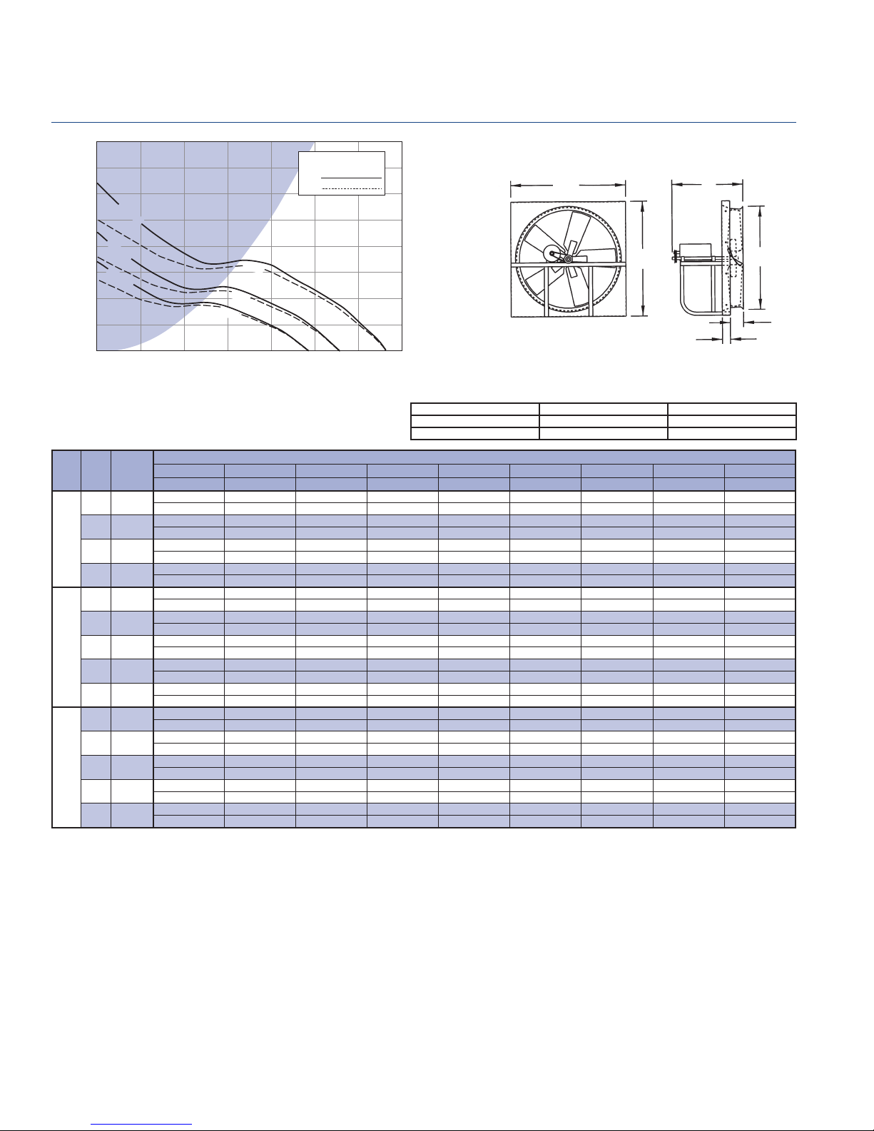
BHH 36B - Belt Drive Fan Data
Breezeway
1.500
Do not select shaded area.
1.250
1.000
0.750
0.500
0.250
STATIC PRESSURE - Inches W.G.
0.000
HP RPM
2
3
5
901 RPM
759 RPM
662 RPM
0
TIP
SPEED
(FPM)
600 5820
620 6014
640 6208
662 6421
685 6645
705 6839
725 7033
740 7178
759 7362
790 7663
820 7954
850 8245
880 8536
901 8740
5 HP
3 HP
2 HP
8000 120004000
AIR FLOW - CFM
0.000" SP 0.100" SP 0.125" SP 0.200" SP 0.250" SP 0.375" SP 0.500" SP 0.625" SP 0.750" SP
Sones BHP Sones BHP Sones BHP Sones BHP Sones BHP Sones BHP Sones BHP Sones BHP Sones BHP
17640 16310 15889 14627 13470 9971
17.3 1.47 17.8 1.50 18.1 1.51 18.4 1.54 18.7 1.55 19.2 1.61
18228 16964 16557 15387 14347 11251
18.1 1.62 18.5 1.65 18.8 1.66 19.1 1.69 19.4 1.70 19.9 1.76
18816 17615 17220 16079 15148 12174
18.9 1.78 19.3 1.81 19.5 1.82 19.9 1.86 20 1.87 21 1.92
19462 18327 17946 16834 16011 13196
19.8 1.97 20 2.00 20 2.01 21 2.05 21 2.07 21 2.11
20139 19064 18699 17617 16901 14257 10010
21 2.18 21 2.22 21 2.23 22 2.26 22 2.29 22 2.33 24 2.41
20727 19682 19351 18292 17613 15164 12442
22 2.38 22 2.41 22 2.42 23 2.46 23 2.49 23 2.53 24 2.60
21315 20299 20001 18963 18303 16060 13413
23 2.58 23 2.62 23 2.63 24 2.67 24 2.70 24 2.74 25 2.81
21756 20760 20486 19463 18817 16724 14103
23 2.75 24 2.79 24 2.80 25 2.84 25 2.86 25 2.91 26 2.97
22314 21344 21098 20100 19464 17556 14986
24 2.97 25 3.01 25 3.02 26 3.05 26 3.08 26 3.13 27 3.19
23226 22293 22060 21134 20511 18796 16418 14027
26 3.34 26 3.39 26 3.40 27 3.44 27 3.46 27 3.52 28 3.57 29 3.65
24108 23210 22985 22128 21516 19968 17777 15431
27 3.74 28 3.78 28 3.79 29 3.83 29 3.86 29 3.93 30 3.98 30 4.05
24990 24123 23907 23114 22520 21105 19114 16820 14229
29 4.17 29 4.21 30 4.22 30 4.26 31 4.29 31 4.36 31 4.41 32 4.48 33 4.58
25872 25035 24826 24095 23521 22143 20427 18208 16060
30 4.62 31 4.67 31 4.68 32 4.72 32 4.75 32 4.83 32 4.87 33 4.94 34 5.03
26489 25672 25467 24778 24218 22864 21261 19163 17029
31 4.96 32 5.01 32 5.02 33 5.06 34 5.09 34 5.17 34 5.22 34 5.29 35 5.37
Performance shown is for installation Type A: Free Inlet, Free Outlet. Power rating (BHP) does not include drive losses. The sound ratings shown are for loudness values
in fan sones at 5'0" (1.5m) in a hemispherical free fi eld per AMCA standard 301. Values shown are for installation Type A: Free inlet fan sone levels. Performance ratings
do not include the effects of appurtenances in the airstream. For further information on sound classifi cation, see page 40. For accessories, see pages 3 thru 7.
RPM
BHP
2000016000
44
24000 28000
Galv. Panel = 14 gauge Wall Opening = 44 3/4 in.sq. Peak BHP = (RPM/511)^3
Galv. Mtr. Plate = 12 gauge Est. Shipping Weight = 190 lbs. Max RPM = 929 (5 HP)
Galv. Structure = 12 gauge Max. Motor Frame Size = 215T
FAN CAPACITY - CUBIC FEET PER MINUTE (CFM)
27
371/
44
3
2
5
PENNBARRY
26
Page 28

Belt Drive Fan Data - BHM 42B
Breezeway
0.750
Do not select shaded area.
3 HP
RPM
BHP
50
Galv. Panel = 14 gauge Wall Opening = 50 3/4 in.sq. Peak BHP = (RPM/388)^3
Galv. Mtr. Plate = 12 gauge Est. Shipping Weight = 225 lbs. Max RPM = 583 (3 HP)
Galv. Structure = 12 gauge Max. Motor Frame Size = 215T
FAN CAPACITY - CUBIC FEET PER MINUTE (CFM)
27
1
/
50
3
43
2
5
0.625
0.500
0.375
0.250
STATIC PRESSURE - Inches W.G.
0.125
0.000
HP RPM
260 2930
1/3
279 3144
300 3381
1/2
322 3629
350 3944
3/4
370 4170
380 4283
1
390 4395
396 4463
420 4733
1 1/2
440 4959
456 5139
470 5297
485 5466
2
495 5579
502 5658
525 5917
545 6142
3
560 6311
576 6492
0
576 RPM
502 RPM
456 RPM
396 RPM
370 RPM
322 RPM
279 RPM
1/3 HP
4000
TIP
SPEED
(FPM)
0.000" SP 0.100" SP 0.125" SP 0.200" SP 0.250" SP 0.300" SP 0.375" SP 0.500" SP 0.625" SP
Sones BHP Sones BHP Sones BHP Sones BHP Sones BHP Sones BHP Sones BHP Sones BHP Sones BHP
2 HP
1 1/2 HP
1 HP
3/4 HP
1/2 HP
120008000
AIR FLOW - CFM
16000 20000 24000 28000
12463 7191
7.3 0.29 6.5 0.30
13374 8659
8.3 0.35 7.5 0.36
14381 10292 8779
9.3 0.44 8.8 0.45 8.3 0.45
15436 11854 10477
10.4 0.55 10.1 0.56 9.7 0.55
16778 13727 12550
12.0 0.70 11.9 0.72 11.5 0.72
17737 14950 13949 10376
13.1 0.83 13.2 0.84 12.8 0.85 11.6 0.86
18216 15518 14638 11145
13.7 0.90 13.8 0.91 13.5 0.92 12.3 0.92
18695 16081 15266 11885
14.2 0.97 14.3 0.98 14.2 0.99 12.9 0.98
18983 16417 15638 12360
14.5 1.01 14.7 1.02 14.6 1.04 13.4 1.02
20134 17749 17075 14238 12097
15.8 1.21 16.1 1.21 16.2 1.23 15.1 1.22 14.4 1.24
21092 18844 18201 15682 13601
17.1 1.39 17.4 1.39 17.5 1.41 16.7 1.42 15.8 1.40
21859 19702 19093 16808 14865 12943
18.2 1.55 18.5 1.55 18.6 1.56 18.1 1.59 17.2 1.57 16.6 1.60
22531 20449 19867 17782 15951 13992
19.1 1.70 19.4 1.70 19.5 1.70 19.2 1.75 18.4 1.72 17.6 1.72
23250 21243 20690 18791 17040 15139
20 1.86 20 1.86 20 1.86 20 1.92 19.8 1.90 19.0 1.88
23729 21771 21234 19415 17751 15930
21 1.98 21 1.98 21 1.98 21 2.03 21 2.03 20 2.00
24065 22139 21609 19849 18244 16478 13791
21 2.07 21 2.07 22 2.06 22 2.11 21 2.12 21 2.09 20 2.14
25167 23344 22837 21242 19848 18215 15608
23 2.36 23 2.37 23 2.36 23 2.40 23 2.43 23 2.40 22 2.40
26126 24385 23896 22374 21182 19639 17144
24 2.64 24 2.65 24 2.65 25 2.68 25 2.72 24 2.71 24 2.67
26845 25162 24687 23216 22114 20692 18325
25 2.87 25 2.88 25 2.87 26 2.90 26 2.94 25 2.95 25 2.90
27612 25988 25526 24107 23099 21804 19564 15578
26 3.12 26 3.13 27 3.13 27 3.14 27 3.18 27 3.21 27 3.16 27 3.25
Performance shown is for installation Type A: Free Inlet, Free Outlet. Power rating (BHP) does not include drive losses. The sound ratings shown are for loudness values
in fan sones at 5'0" (1.5m) in a hemispherical free fi eld per AMCA standard 301. Values shown are for installation Type A: Free inlet fan sone levels. Performance ratings
do not include the effects of appurtenances in the airstream. For further information on sound classifi cation, see page 40. For accessories, see pages 3 thru 7.
PENNBARRY
27
Page 29
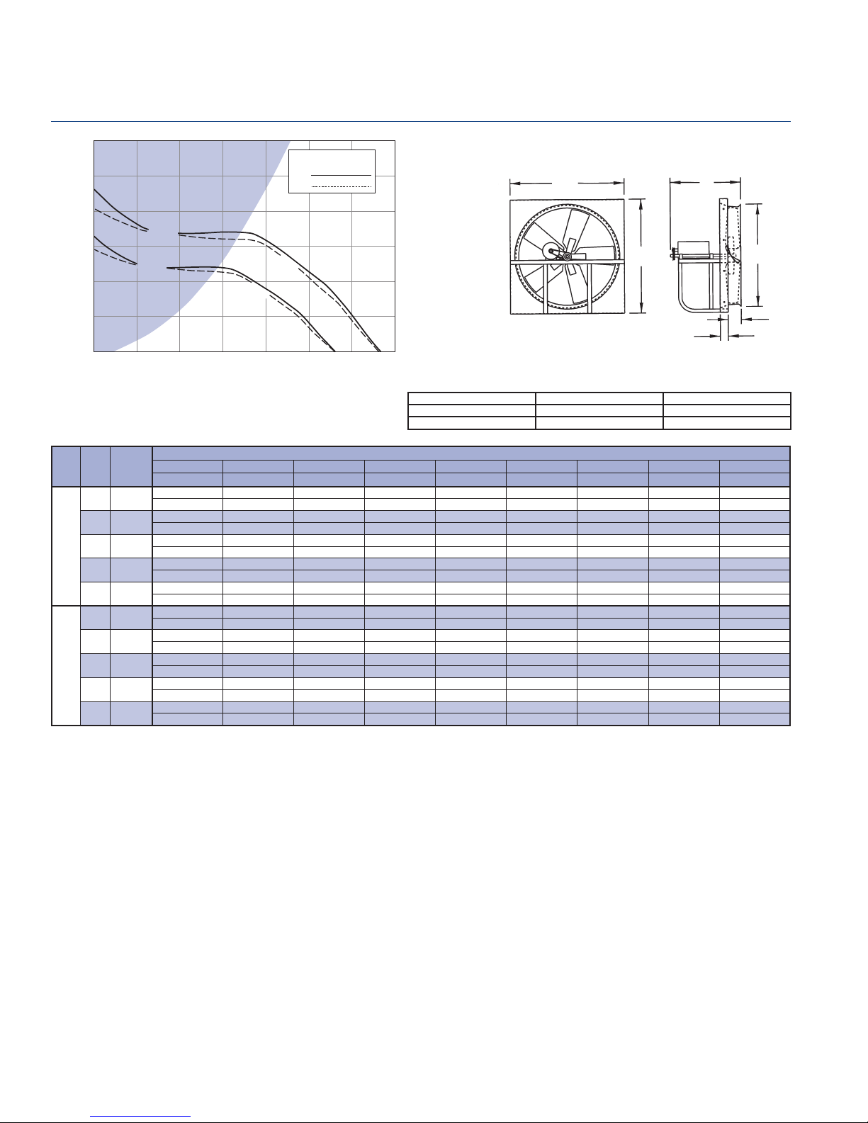
BHH 42B - Belt Drive Fan Data
Breezeway
1.200
Do not select shaded area.
3 HP
5 HP
RPM
BHP
30000 35000
Galv. Panel = 14 gauge Wall Opening = 50 3/4 in.sq. Peak BHP = (RPM/387)^3
Galv. Mtr. Plate = 12 gauge Est. Shipping Weight = 245 lbs. Max RPM = 699 (5 HP)
Galv. Structure = 12 gauge Max. Motor Frame Size = 215T
1.000
0.800
683 RPM
0.600
575 RPM
0.400
STATIC PRESSURE - Inches W.G.
0.200
0.000
0 20000 25000
5000
10000 15000
AIR FLOW - CFM
50
50
27
431/
2
5
3
HP RPM
525 5917
535 6029
550 6199
3
565 6368
575 6480
600 6762
625 7044
645 7269
5
665 7495
683 7697
TIP
SPEED
(FPM)
0.000" SP 0.100" SP 0.125" SP 0.200" SP 0.250" SP 0.300" SP 0.375" SP 0.500" SP 0.625" SP
Sones BHP Sones BHP Sones BHP Sones BHP Sones BHP Sones BHP Sones BHP Sones BHP Sones BHP
25530 23361 22879 21213 19799 18129 15429
22 2.31 23 2.36 23 2.36 23 2.39 23 2.41 22 2.38 21 2.37
26017 23879 23406 21805 20484 18860 16244
23 2.45 23 2.50 23 2.50 24 2.53 23 2.55 23 2.52 22 2.51
26746 24653 24193 22687 21499 19941 17450
24 2.66 24 2.71 24 2.71 25 2.74 24 2.78 24 2.75 23 2.72
27475 25433 24977 23561 22405 20989 18635
25 2.88 25 2.94 25 2.94 25 2.96 26 3.00 25 2.99 24 2.95
27962 25955 25497 24141 23005 21681 19384
26 3.04 26 3.09 26 3.10 26 3.11 26 3.15 26 3.16 25 3.12
29178 27255 26794 25527 24488 23387 21221 17224
27 3.45 28 3.51 28 3.52 28 3.53 28 3.56 28 3.61 27 3.56 26 3.57
30393 28547 28086 26867 25953 24908 23001 19342
29 3.90 29 3.96 29 3.98 29 3.99 30 4.01 30 4.06 29 4.05 28 4.00
31366 29577 29130 27931 27113 26100 24387 20935
30 4.28 31 4.35 31 4.37 31 4.38 31 4.39 31 4.44 31 4.46 30 4.39
32338 30604 30170 28989 28227 27281 25753 22461 18633
32 4.70 32 4.76 32 4.78 32 4.80 32 4.80 32 4.85 33 4.91 32 4.82 31 4.92
33214 31525 31102 29936 29194 28334 26900 23788 20347
33 5.09 33 5.16 33 5.17 34 5.20 34 5.20 34 5.23 34 5.31 33 5.24 33 5.22
FAN CAPACITY - CUBIC FEET PER MINUTE (CFM)
Performance shown is for installation Type A: Free Inlet, Free Outlet. Power rating (BHP) does not include drive losses. The sound ratings shown are for loudness values
in fan sones at 5'0" (1.5m) in a hemispherical free fi eld per AMCA standard 301. Values shown are for installation Type A: Free inlet fan sone levels. Performance ratings
do not include the effects of appurtenances in the airstream. For further information on sound classifi cation, see page 40. For accessories, see pages 3 thru 7.
PENNBARRY
28
Page 30
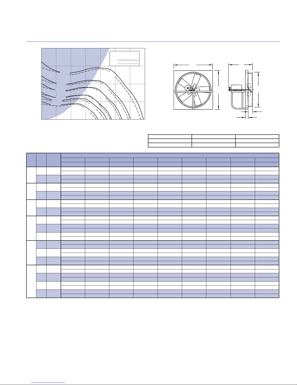
0.500
0.375
442 RPM
Do not select shaded area.
RPM
BHP
3 HP
Belt Drive Fan Data - BHM 48B
Breezeway
56
27
0.250
0.125
STATIC PRESSURE - Inches W.G.
0.000
HP RPM
225 2882
1/2
246 3151
265 3395
3/4
283 3625
295 3779
1
304 3894
320 4099
1 1/2
335 4291
349 4471
365 4676
2
375 4804
385 4932
400 5124
415 5316
3
430 5508
442 5662
385 RPM
349 RPM
M
304 RP
283 RPM
246 RPM
50000 10000 15000
TIP
SPEED
(FPM)
0.000" SP 0.100" SP 0.125" SP 0.200" SP 0.250" SP 0.300" SP 0.375" SP 0.500" SP 0.625" SP
Sones BHP Sones BHP Sones BHP Sones BHP Sones BHP Sones BHP Sones BHP Sones BHP Sones BHP
1/2 HP
AIR FLOW - CFM
1 1/2 H
1 HP
3/4 HP
20000 25000
2 HP
56
P
2
30000 35000
Galv. Panel = 14 gauge Wall Opening = 57 in.sq. Peak BHP = (RPM/298)^3
Galv. Mtr. Plate = 12 gauge Est. Shipping Weight = 235 lbs. Max RPM = 450 (3 HP)
Galv. Structure = 12 gauge Max. Motor Frame Size = 215T
FAN CAPACITY - CUBIC FEET PER MINUTE (CFM)
17535
6.5 0.43
19171 13913
7.6 0.56 8.7 0.55
20652 16061 14144
8.6 0.70 9.2 0.69 10.0 0.68
22055 17972 16473
9.5 0.85 9.7 0.84 10.7 0.83
22990 19220 17819
10.2 0.96 10.1 0.95 11.0 0.95
23691 20174 18783
10.7 1.05 10.4 1.04 11.3 1.04
24938 21854 20470
11.6 1.23 10.9 1.23 11.8 1.21
26107 23377 22037 17862
12.6 1.41 11.5 1.42 12.4 1.39 14.9 1.37
27198 24641 23517 19805
13.5 1.59 12.2 1.61 12.8 1.59 15.6 1.56
28445 26072 25182 21638
14.5 1.82 13.3 1.84 13.3 1.83 15.7 1.79
29225 26959 26178 22739 20037
15.1 1.97 13.9 2.00 13.7 1.99 15.9 1.95 17.7 1.92
30004 27843 27082 23809 21473
15.7 2.13 14.6 2.16 14.3 2.16 16.2 2.11 18.1 2.09
31173 29161 28428 25394 23272
16.8 2.39 15.7 2.42 15.4 2.42 16.7 2.36 18.3 2.35
32342 30470 29764 26955 24963 22557
17.9 2.67 16.7 2.71 16.4 2.71 17.2 2.64 18.5 2.64 20 2.61
33511 31737 31090 28539 26572 24552
19.0 2.97 17.9 3.01 17.4 3.01 17.9 2.95 19.0 2.93 20 2.92
34446 32720 32146 29804 27843 25929
19.8 3.23 18.7 3.27 18.3 3.27 18.5 3.23 19.4 3.19 21 3.18
1
/
49
2
5
Performance shown is for installation Type A: Free Inlet, Free Outlet. Power rating (BHP) does not include drive losses. The sound ratings shown are for loudness values
in fan sones at 5'0" (1.5m) in a hemispherical free fi eld per AMCA standard 301. Values shown are for installation Type A: Free inlet fan sone levels. Performance ratings
do not include the effects of appurtenances in the airstream. For further information on sound classifi cation, see page 40. For accessories, see pages 3 thru 7.
PENNBARRY
29
Page 31
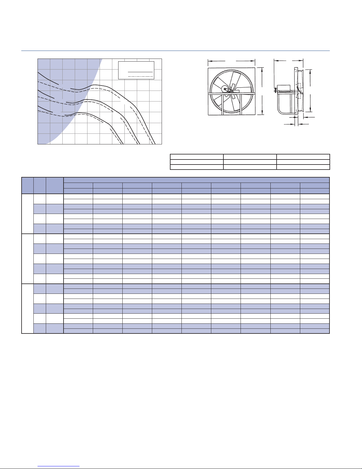
BHH 48B - Belt Drive Fan Data
Breezeway
1.000
0.875
0.750
0.625
0.500
0.375
0.250
STATIC PRESSURE - Inches W.G.
0.125
0.000
HP RPM
400 5124
420 5380
3
440 5636
456 5842
475 6085
495 6341
515 6597
5
530 6789
541 6930
560 7174
580 7430
600 7686
7 1/2
610 7814
621 7955
Do not select shaded area.
RPM
BHP
621 RPM
541 RPM
456 RPM
100000 20000 30000
AIR FLOW - CFM
TIP
SPEED
(FPM)
0.000" SP 0.100" SP 0.125" SP 0.200" SP 0.250" SP 0.300" SP 0.375" SP 0.500" SP 0.625" SP
Sones BHP Sones BHP Sones BHP Sones BHP Sones BHP Sones BHP Sones BHP Sones BHP Sones BHP
7 1/2 HP
5 HP
3 HP
40000 50000
Galv. Panel = 14 gauge Wall Opening = 57 in.sq. Peak BHP = (RPM/307)^3
Galv. Mtr. Plate = 12 gauge Est. Shipping Weight = 255 lbs. Max RPM = 624 (7.5 HP)
Galv. Structure = 12 gauge Max. Motor Frame Size = 215T
FAN CAPACITY - CUBIC FEET PER MINUTE (CFM)
56
56
30576 27854 27180 24367 20747
16.9 2.15 17.0 2.20 17.0 2.21 17.1 2.20 17.3 2.15
32105 29500 28881 26638 23551 19909
18.2 2.49 18.3 2.54 18.4 2.55 18.5 2.54 18.7 2.48 19.2 2.50
33634 31136 30544 28614 26332 22985
19.4 2.87 19.7 2.91 19.8 2.93 20 2.92 20 2.92 21 2.86
34857 32437 31866 30030 28331 25224
20 3.19 21 3.23 21 3.25 21 3.26 21 3.26 22 3.16
36309 33975 33427 31697 30349 27882 23178
22 3.61 22 3.65 22 3.67 23 3.69 23 3.68 23 3.64 24 3.62
37838 35586 35061 33434 32263 30476 26131
23 4.08 24 4.12 24 4.14 24 4.18 24 4.16 24 4.17 25 4.06
39367 37191 36685 35156 34031 32689 28930
24 4.60 25 4.63 25 4.65 26 4.71 26 4.69 26 4.69 27 4.57
40514 38397 37899 36426 35345 34248 31025 21858
25 5.01 26 5.05 26 5.07 27 5.13 27 5.12 27 5.10 28 5.05 32 5.05
41355 39281 38786 37344 36303 35232 32527 25495
26 5.33 27 5.36 27 5.38 28 5.45 28 5.45 28 5.43 29 5.43 31 5.34
42807 40803 40315 38921 37948 36913 34884 28531
27 5.91 28 5.95 28 5.96 29 6.03 29 6.05 30 6.03 30 6.04 32 5.91
44336 42401 41918 40572 39667 38668 36987 31355
29 6.57 29 6.60 30 6.61 31 6.69 31 6.73 31 6.71 32 6.69 34 6.51
45865 43995 43527 42214 41347 40408 38959 34154 27558
31 7.27 31 7.31 31 7.32 32 7.39 33 7.44 33 7.44 33 7.40 35 7.26 39 7.29
46629 44790 44330 43032 42180 41273 39848 35549 29378
31 7.64 32 7.68 32 7.69 33 7.76 34 7.81 34 7.82 34 7.79 36 7.69 39 7.66
47470 45663 45211 43930 43093 42221 40821 37068 31169
32 8.06 33 8.10 33 8.11 34 8.18 35 8.23 35 8.25 35 8.22 37 8.19 40 8.07
27
491/
2
5
2
Performance shown is for installation Type A: Free Inlet, Free Outlet. Power rating (BHP) does not include drive losses. The sound ratings shown are for loudness values
in fan sones at 5'0" (1.5m) in a hemispherical free fi eld per AMCA standard 301. Values shown are for installation Type A: Free inlet fan sone levels. Performance ratings
do not include the effects of appurtenances in the airstream. For further information on sound classifi cation, see page 40. For accessories, see pages 3 thru 7.
PENNBARRY
30
Page 32

Belt Drive Fan Data - BHH 54B
Breezeway
2.000
1.750
1.500
1.250
1.000
0.750
0.500
STATIC PRESSURE - Inches W.G.
0.250
0.000
HP RPM
240 3458
3/4
260 3747
270 3891
1
279 4020
295 4251
1 1/2
310 4467
320 4611
335 4827
2
345 4971
353 5087
370 5332
385 5548
3
395 5692
405 5836
425 6124
440 6340
5
455 6557
470 6773
482 6946
500 7205
515 7421
7 1/2
530 7637
545 7853
552 7954
560 8070
570 8214
580 8358
10
590 8502
600 8646
608 8761
320 RPM
279
260 RPM
608 RPM
552 RPM
482 RPM
405 RPM
353 RPM
RPM
100000 20000 30000
TIP
SPEED
(FPM)
1 1/2 HP
1 HP
3/4 HP
0.000" SP 0.125" SP 0.250" SP 0.375" SP 0.500" SP 0.625" SP 0.750" SP 0.875" SP 1.000" SP
Sones BHP Sones BHP Sones BHP Sones BHP Sones BHP Sones BHP Sones BHP Sones BHP Sones BHP
20273 13846
9.4 0.62 9.3 0.67
21963 16686
10.8 0.79 10.7 0.85
22807 17862
11.5 0.88 11.4 0.95
23568 18956
12.2 0.97 12.1 1.05
24919 20748 9672
13.5 1.15 13.5 1.24 13.1 1.23
26186 22338 13544
14.7 1.33 14.7 1.44 14.3 1.45
27031 23335 15836
15.5 1.47 15.5 1.58 15.1 1.60
28298 24816 18801
16.8 1.68 16.7 1.80 16.4 1.83
29143 25794 20561
17.7 1.84 17.6 1.96 1.74 1.99
29819 26572 21732 10459
18.4 1.97 18.4 2.09 18.1 2.13 17.8 2.14
31255 28212 23868 14133
19.9 2.26 19.9 2.40 19.6 2.45 19.2 2.44
32522 29641 25647 17818
21 2.55 21 2.69 21 2.76 21 2.78
33367 30581 26861 20090
22 2.76 22 2.90 22 2.98 22 3.01
34211 31517 28023 22082 11754
22 2.97 23 3.12 23 3.21 23 3.25 22 3.25
35901 33377 30180 25594 15735
24 3.43 24 3.59 26 3.71 25 3.73 24 3.70
37168 34763 31751 27673 19524
25 3.81 26 3.98 27 4.11 27 4.13 26 4.14
38435 36143 33245 29448 22949 13413
27 4.21 27 4.39 28 4.53 29 4.56 28 4.60 27 4.59
39702 37516 34726 31225 25918 16236
28 4.64 29 4.83 30 4.97 30 5.03 29 5.07 28 4.99
40716 38611 35903 32683 28044 19369
30 5.01 30 5.21 31 5.34 31 5.42 31 5.45 29 5.42
42236 40247 37655 34753 30842 23683 14887
31 5.59 32 5.80 33 5.94 33 6.05 33 6.06 32 6.09 31 6.08
43503 41580 39104 36372 32784 27069 17823
33 6.11 33 6.33 35 6.47 35 6.61 35 6.62 34 6.68 32 6.57
44771 42902 40544 37975 34541 29784 21732
35 6.66 35 6.88 37 7.03 37 7.20 37 7.21 36 7.26 34 7.21
46038 44220 41969 39497 36335 32424 25320 16686
37 7.24 37 7.47 39 7.63 39 7.80 39 7.84 38 7.87 37 7.88 36 7.82
46629 44835 42628 40194 37187 33507 26917 18122
37 7.52 38 7.76 40 7.92 40 8.09 40 8.14 39 8.16 38 8.20 37 8.07
47305 45536 43379 40988 38154 34618 28723 20234
39 7.85 39 8.09 41 8.26 41 8.43 41 8.50 40 8.52 39 8.58 38 8.46
48150 46412 44315 41976 39331 35969 30734 22838
40 8.28 41 8.52 42 8.70 42 8.87 42 8.96 42 8.98 41 9.05 39 8.96
48994 47287 45248 42960 40417 37149 32522 25350 17516
41 8.72 42 8.97 44 9.16 44 9.33 44 9.44 43 9.45 42 9.52 41 9.47 40 9.46
49839 48160 46178 43940 41497 38320 34290 27654 19344
43 9.18 44 9.43 46 9.63 46 9.80 46 9.93 45 9.95 44 9.99 43 10.00 42 9.85
50684 49033 47106 44915 42570 39482 36038 29928 21981
45 9.66 45 9.91 47 10.11 48 10.29 48 10.44 47 10.46 46 10.49 45 10.54 44 10.41
51360 49731 47847 45693 43425 40462 37167 31726 24064
46 10.05 47 10.31 49 10.51 49 10.69 49 10.87 48 10.88 47 10.91 46 10.99 45 10.86
10 HP
7 1/2 HP
5 HP
3 HP
2 HP
AIR FLOW - CFM
Performance shown is for installation Type A: Free Inlet, Free Outlet. Power rating (BHP) does not include drive losses. The sound ratings shown are for loudness values
in fan sones at 5'0" (1.5m) in a hemispherical free fi eld per AMCA standard 301. Values shown are for installation Type A: Free inlet fan sone levels. Performance ratings
do not include the effects of appurtenances in the airstream. For further information on sound classifi cation, see page 40. For accessories, see pages 3 thru 7.
Do not select shaded area.
RPM
BHP
40000 50000
62
Galv. Panel = 14 gauge Wall Opening = 63 in.sq. Peak BHP = (RPM/273)^3
Galv. Mtr. Plate = 10 gauge Est. Shipping Weight = 430 lbs. Max RPM = 623 (10 HP)
Galv. Structure = 12 gauge Max. Motor Frame Size = 284T
FAN CAPACITY - CUBIC FEET PER MINUTE (CFM)
35
1
/
55
62
3
2
5
PENNBARRY
31
Page 33

BHH 60B - Belt Drive Fan Data
Breezeway
1.750
1.500
1.250
1.000
0.750
0.500
STATIC PRESSURE - Inches W.G.
0.250
0.000
HP RPM
3/4
1
1 1/2
2
3
5
7 1/2
10
534 RPM
485 RPM
423 RPM
356 RPM
310 RPM
281 RPM
245 RPM
228 RPM
0
TIP
SPEED
(FPM)
210 3356
228 3643
235 3755
245 3915
260 4155
270 4315
281 4490
290 4634
300 4794
310 4954
325 5194
335 5353
345 5513
356 5689
370 5913
385 6152
400 6392
415 6632
423 6760
440 7031
455 7271
465 7431
475 7591
485 7750
495 7910
505 8070
515 8230
525 8390
530 8469
534 8533
10 HP
7 1/2 HP
5 HP
3 H
P
2 HP
1 1/2 HP
1 H
P
3/4 HP
10000
3000020000
AIR FLOW - CFM
40000 50000
0.000" SP 0.125" SP 0.250" SP 0.375" SP 0.500" SP 0.625" SP 0.750" SP 0.875" SP 1.000" SP
Sones BHP Sones BHP Sones BHP Sones BHP Sones BHP Sones BHP Sones BHP Sones BHP Sones BHP
22971 13646
9.8 0.62 9.9 0.66
24940 17920
11.3 0.79 11.4 0.84
25706 19088
11.9 0.86 12.0 0.92
26800 20709
12.8 0.98 12.9 1.04
28440 22938 7039
14.2 1.17 14.3 1.24 14.4 1.26
29534 24360 8721
15.1 1.31 15.2 1.39 15.4 1.37
30737 25903 13611
16.2 1.48 16.2 1.57 16.5 1.57
31722 27132 17165
17.1 1.62 17.1 1.72 17.3 1.74
32816 28483 20158
18.0 1.80 18.1 1.91 18.3 1.95
33910 29822 22604
19.1 1.98 19.1 2.10 19.3 2.14
35551 31808 25787 9625
20 2.28 21 2.42 21 2.43 20 2.41
36644 33118 27430 11830
21 2.50 22 2.65 22 2.66 21 2.59
37738 34366 29049 17018
23 2.73 23 2.88 23 2.90 22 2.91
38942 35715 30753 21343
24 3.00 24 3.16 25 3.18 24 3.21
40473 37421 32769 25420 10303
26 3.37 27 3.53 27 3.58 26 3.66 23 3.60
42114 39237 34896 28868 13045
28 3.80 28 3.97 29 4.04 28 4.08 25 3.94
43755 41042 36989 31906 20298
29 4.26 29 4.44 30 4.53 30 4.53 28 4.53
45395 42837 39032 34361 25852 11718
30 4.75 30 4.94 31 5.05 32 5.05 30 5.10 28 5.07
46271 43790 40112 35652 28149 13036
31 5.03 31 5.23 32 5.35 33 5.34 31 5.45 29 5.29
48130 45809 42387 38243 32323 18846
33 5.66 33 5.87 34 6.01 35 6.01 34 6.11 32 5.90
49771 47543 44374 40397 35623 25763 12895
35 6.26 35 6.48 36 6.64 37 6.65 36 6.68 34 6.69 33 6.68
50865 48684 45690 41818 37356 29197 14568
36 6.69 36 6.91 38 7.08 38 7.11 38 7.11 36 7.19 34 7.01
51959 49824 46998 43228 38994 32061 17146
38 7.13 38 7.35 38 7.54 40 7.58 39 7.57 38 7.72 36 7.38
53053 50962 48244 44627 40614 34588 22517 12956
38 7.59 38 7.81 39 8.02 41 8.07 40 8.05 39 8.22 37 8.01 36 8.17
54146 52098 49473 46000 42219 36818 26877 14457
39 8.07 39 8.30 40 8.51 42 8.58 42 8.55 41 8.68 39 8.61 38 8.55
55240 53233 50697 47361 42715 39019 30715 16290
40 8.56 40 8.80 41 9.01 43 9.10 43 9.09 42 9.15 41 9.17 39 8.95
56334 54366 51917 48714 45158 40959 33599 19170 13321
41 9.08 41 9.33 42 9.54 44 9.65 44 9.64 44 9.66 43 9.81 41 9.38 41 9.84
57428 55497 53133 50058 46591 42606 36441 25029 14831
43 9.62 43 9.87 44 10.19 45 10.22 46 10.22 45 10.23 44 10.47 43 10.20 42 10.26
57975 56062 53739 50728 47303 43423 37599 27189 15589
43 9.90 43 10.15 44 10.38 46 10.51 46 10.52 46 10.52 45 10.74 44 10.54 43 10.48
58413 56514 54224 51262 47871 44074 38497 28771 16301
44 10.13 44 10.38 45 10.61 46 10.74 47 10.76 47 10.76 46 10.95 44 10.80 44 10.66
Performance shown is for installation Type A: Free Inlet, Free Outlet. Power rating (BHP) does not include drive losses. The sound ratings shown are for loudness values
in fan sones at 5'0" (1.5m) in a hemispherical free fi eld per AMCA standard 301. Values shown are for installation Type A: Free inlet fan sone levels. Performance ratings
do not include the effects of appurtenances in the airstream. For further information on sound classifi cation, see page 40. For accessories, see pages 3 thru 7.
PENNBARRY
32
Do not select shaded area.
RPM
BHP
FAN CAPACITY - CUBIC FEET PER MINUTE (CFM)
68
68
Galv. Panel = 14 gauge Wall Opening = 69 in.sq. Peak BHP = (RPM/240)^3
Galv. Mtr. Plate = 10 gauge Est. Shipping Weight = 460 lbs. Max RPM = 545 (10 HP)
60000
Galv. Structure = 12 gauge Max. Motor Frame Size = 284T
35
3
1
/
61
2
5
Page 34

Belt Drive Fan Data - BCH 24
Breezeway
2.400
2.000
0
1222 RPM
1063 RPM
924 RPM
858 RPM
SPEED
(FPM)
1659 RPM
1505 RPM
1310 RPM
3/4 HP
1/3 HP
1/2 HP
1/4 HP
40002000
AIR FLOW - CFM
TIP
0.000" SP 0.100" SP 0.125" SP 0.150" SP 0.200" SP 0.250" SP 0.375" SP 0.500" SP 0.625" SP 0.750" SP
Sones BHP Sones BHP Sones BHP Sones BHP Sones BHP Sones BHP Sones BHP Sones BHP Sones BHP Sones BHP
6000 8000
2851
5.6 0.06
3516 2617 2075
8.3 0.11 8.0 0.12 8.1 0.12
4429 3851 3636 3402 2586
12.5 0.22 12.2 0.24 12.2 0.24 12.1 0.25 12.2 0.24
4751 4210 4059 3845 3295 2446
13.7 0.28 13.4 0.29 13.3 0.30 13.3 0.30 13.3 0.30 13.7 0.29
4817 4284 4145 3935 3434 2595
14.0 0.29 13.7 0.31 13.6 0.31 13.5 0.31 13.6 0.31 13.9 0.31
5039 4528 4403 4231 3809 3086
15.0 0.33 14.7 0.35 14.7 0.35 14.6 0.35 14.6 0.36 14.8 0.35
5116 4612 4489 4332 3930 3261
15.4 0.34 15.1 0.37 15.0 0.37 14.9 0.37 15.0 0.38 15.1 0.37
5149 4649 4526 4376 3977 3335
15.6 0.35 15.2 0.37 15.2 0.37 15.1 0.38 15.1 0.38 15.3 0.37
5537 5065 4956 4842 4510 4102
16.9 0.44 16.7 0.46 16.6 0.46 16.6 0.46 16.4 0.47 16.6 0.48
5886 5434 5338 5231 4974 4625 3147
18.2 0.52 18.0 0.55 17.9 0.56 17.9 0.56 17.8 0.56 17.9 0.57 18.5 0.56
5924 5475 5379 5274 5025 4679 3233
18.4 0.53 18.2 0.56 18.1 0.57 18.1 0.57 18.0 0.57 18.0 0.58 18.7 0.57
6423 5998 5909 5820 5624 5355 4337 2659
21 0.68 21 0.71 21 0.72 21 0.73 20 0.73 20 0.74 21 0.73 22 0.75
6644 6228 6143 6057 5871 5645 4800 3265
22 0.75 22 0.78 22 0.79 22 0.80 22 0.80 22 0.81 22 0.83 23 0.81
6766 6355 6271 6187 6007 5802 5000 3566
23 0.79 22 0.83 22 0.84 22 0.84 22 0.85 22 0.85 23 0.87 23 0.85
6810 6401 6318 6234 6056 5860 5072 3665
23 0.81 22 0.84 22 0.85 22 0.86 22 0.86 22 0.87 23 0.89 23 0.86
6921 6516 6434 6352 6178 5996 5250 3909
23 0.85 23 0.88 23 0.89 23 0.90 23 0.91 23 0.91 23 0.93 24 0.91
7143 6745 6666 6586 6422 6245 5573 4403
24 0.93 24 0.97 24 0.98 24 0.94 24 1.00 24 1.00 24 1.02 25 1.00
7253 6859 6781 6703 6543 6369 5727 4652 3173
25 0.98 24 1.01 24 1.02 25 1.03 25 1.04 25 1.04 25 1.07 26 1.04 26 1.07
7309 6917 6839 6761 6603 6431 5803 4776 3325
25 1.00 25 1.04 25 1.05 25 1.05 25 1.07 25 1.07 25 1.09 26 1.07 27 1.09
7586 7202 7127 7052 6902 6739 6181 5365 4034
27 1.12 27 1.16 27 1.17 27 1.17 27 1.19 27 1.19 27 1.22 27 1.22 28 1.19
8029 7660 7586 7515 7373 7227 6771 6122 5020 3703
31 1.33 31 1.37 31 1.38 31 1.39 31 1.40 31 1.42 31 1.43 31 1.46 31 1.42 32 1.44
8333 7978 7900 7831 7695 7559 7166 6554 5687 4471
33 1.48 33 1.52 33 1.53 33 1.54 33 1.56 33 1.58 33 1.59 33 1.62 34 1.60 35 1.58
8416 8064 7985 7918 7783 7648 7273 6669 5862 4655
34 1.53 34 1.57 34 1.58 34 1.59 34 1.61 34 1.63 34 1.63 34 1.67 34 1.66 35 1.63
8582 8237 8156 8090 7957 7825 7463 6897 6205 5018
34 1.62 34 1.66 34 1.67 34 1.68 34 1.70 34 1.72 34 1.73 34 1.77 35 1.78 35 1.73
8859 8525 8441 8376 8248 8119 7774 7272 6656 5643
35 1.78 35 1.83 35 1.84 35 1.85 35 1.87 35 1.89 35 1.90 35 1.94 35 1.96 36 1.90
9186 8864 8783 8713 8589 8465 8137 7708 7146 6351
37 1.99 37 2.03 37 2.04 37 2.05 37 2.08 37 2.10 37 2.12 37 2.15 37 2.18 37 2.15
1.600
1.200
0.800
STATIC PRESSURE - Inches W.G.
0.400
0.000
HP RPM
515 3236
635 3990
1/4
800 5027
858 5391
870 5466
1/3
910 5718
924 5806
930 5843
1/2
1000 6283
1063 6679
1070 6723
1160 7288
3/4
1200 7540
1222 7678
1230 7728
1250 7854
1
1290 8105
1310 8231
1320 8294
1370 8608
1 1/2
1450 9111
1505 9456
1520 9550
1550 9739
2
1600 10053
1659 10424
Performance shown is for installation Type A: Free Inlet, Free Outlet. Power rating (BHP) does not include drive losses. The sound ratings shown are for loudness values
in fan sones at 5'0" (1.5m) in a hemispherical free fi eld per AMCA standard 301. Values shown are for installation Type A: Free inlet fan sone levels. Performance ratings
do not include the effects of appurtenances in the airstream. For further information on sound classifi cation, see page 40. For accessories, see pages 3 thru 7.
Do not select shaded area.
RPM
BHP
2 HP
1 1/2 HP
1 HP
28
Carbon Steel Panel = 16 gauge Wall Opening = 28 3/4 in.sq. Peak BHP = (RPM/1108)^3
10000
Carbon Stl. Mtr. Plate = 10 gauge Wall Shutter ID = 28 in.sq. Max RPM = 1659 (2 HP)
Carbon Steel Tube = 16 gauge Est. Shipping Weight = 100 lbs. Max. Motor Frame Size = 145T
FAN CAPACITY - CUBIC FEET PER MINUTE (CFM)
3
3
28
16
25
PENNBARRY
33
Page 35

BCH 30 - Belt Drive Fan Data
Breezeway
2.400
2.200
2.000
1.800
1.600
1.400
1.200
1.000
0.800
0.600
0.400
STATIC PRESSURE - Inches W.G.
0.200
0.000
HP RPM
410 3220
480 3770
1/4
620 4869
676 5309
680 5341
1/3
727 5710
730 5733
1/2
837 6574
840 6597
3/4
962 7556
970 7618
990 7775
1
1010 7933
1031 8097
1040 8168
1095 8600
1 1/2
1140 8954
1184 9299
1190 9346
2
1250 9817
1306 10257
1315 10328
1360 10681
1420 11153
3
1460 11467
1498 11765
727 RPM
0
1031 RPM
962 RPM
837 RPM
676 RPM
SPEED
(FPM)
1498 RPM
1306 RPM
1184 RPM
1/2 HP
1/4 HP
40002000
TIP
0.000" SP 0.100" SP 0.125" SP 0.150" SP 0.200" SP 0.250" SP 0.375" SP 0.500" SP 0.625" SP 0.750" SP
Sones BHP Sones BHP Sones BHP Sones BHP Sones BHP Sones BHP Sones BHP Sones BHP Sones BHP Sones BHP
1 HP
3/4 HP
6000 8000
AIR FLOW - CFM
3891
5.9 0.07
4555
7.7 0.10
5884 4335 3853 3247
12.0 0.23 13.0 0.23 13.9 0.22 13.4 0.23
6415 5035 4625 4171
13.9 0.29 14.6 0.30 15.2 0.29 16.2 0.29
6543 5083 4676 4233
14.0 0.30 14.8 0.30 15.3 0.30 16.3 0.29
6899 5637 5276 4886 3951
15.7 0.36 16.3 0.37 16.8 0.37 17.5 0.36 17.8 0.37
6927 5672 5314 4926 4005
15.8 0.37 16.4 0.38 16.9 0.37 17.6 0.37 18.0 0.38
7943 6957 6583 6275 5609 4817
20 0.55 20 0.57 21 0.57 21 0.57 22 0.55 23 0.56
7971 6993 6618 6310 5649 4865
20 0.56 20 0.58 21 0.58 21 0.57 22 0.56 23 0.57
9129 8335 8089 7753 7192 6618 4798
26 0.84 26 0.86 26 0.87 26 0.87 27 0.86 28 0.85 29 0.87
9205 8421 8177 7851 7287 6721 4946
26 0.86 26 0.88 26 0.89 26 0.89 27 0.88 28 0.87 29 0.89
9395 8634 8395 8096 7525 6978 5311
27 0.92 27 0.94 27 0.95 27 0.95 28 0.94 29 0.93 30 0.94
9585 8847 8613 8339 7760 7233 5655
28 0.97 28 0.99 28 1.00 28 1.01 29 1.00 30 0.99 32 0.99
9784 9069 8840 8592 8006 7498 5994
29 1.04 29 1.06 29 1.07 29 1.07 30 1.07 31 1.05 33 1.04
9869 9164 8937 8700 8110 7611 6138
30 1.06 30 1.08 30 1.09 30 1.10 30 1.10 31 1.08 34 1.07
10391 9739 9527 9311 8757 8272 6986
33 1.24 32 1.26 32 1.27 32 1.28 32 1.28 33 1.27 37 1.23
10819 10204 10005 9798 9310 8803 7598 6076
35 1.40 35 1.42 35 1.43 35 1.44 35 1.45 36 1.44 39 1.40 39 1.44
11236 10658 10469 10270 9843 9314 8180 6817
38 1.57 38 1.58 38 1.60 38 1.61 37 1.62 38 1.62 41 1.58 43 1.59
11293 10719 10532 10335 9915 9383 8258 6913
38 1.59 38 1.61 38 1.62 38 1.63 38 1.65 38 1.65 41 1.60 44 1.61
11862 11333 11155 10973 10595 10108 9023 7862 6343
42 1.85 41 1.85 41 1.87 41 1.88 41 1.91 41 1.91 44 1.87 48 1.82 46 1.91
12394 11904 11733 11563 11202 10791 9713 8634 7334
45 2.11 45 2.11 45 2.13 45 2.14 44 2.17 44 2.18 47 2.15 50 2.10 51 2.14
12479 11995 11826 11656 11299 10899 9821 8755 7480
46 2.15 45 2.15 45 2.17 45 2.18 45 2.21 45 2.23 47 2.20 51 2.15 52 2.18
12906 12441 12287 12124 11783 11435 10356 9353 8200 6777
48 2.38 48 2.38 48 2.39 48 2.41 48 2.44 48 2.46 50 2.44 53 2.39 57 2.38 54 2.46
13476 13030 12900 12743 12423 12090 11058 10123 9106 7861
52 2.71 52 2.71 52 2.72 52 2.73 52 2.77 52 2.79 53 2.79 56 2.74 60 2.68 60 2.76
13855 13422 13307 13155 12846 12523 11522 10629 9651 8508
55 2.94 54 2.94 54 2.95 54 2.97 54 3.00 54 3.03 55 3.04 58 2.99 62 2.93 64 2.96
14216 13793 13687 13544 13247 12932 11975 11096 10161 9113
57 3.18 57 3.18 57 3.18 57 3.20 57 3.23 57 3.26 57 3.29 60 3.24 64 3.19 68 3.17
Do not select shaded area.
RPM
BHP
3 HP
2 HP
1 1/2 HP
10000 12000 14000
Performance shown is for installation Type A: Free Inlet, Free Outlet. Power rating (BHP) does not include drive losses. The sound ratings shown are for loudness values
in fan sones at 5'0" (1.5m) in a hemispherical free fi eld per AMCA standard 301. Values shown are for installation Type A: Free inlet fan sone levels. Performance ratings
do not include the effects of appurtenances in the airstream. For further information on sound classifi cation, see page 40. For accessories, see pages 3 thru 7.
PENNBARRY
34
34
Carbon Steel Panel = 16 gauge Wall Opening = 34 3/4 in.sq. Peak BHP = (RPM/877)^3
Carbon Stl. Mtr. Plate = 10 gauge Wall Shutter ID = 34 in.sq. Max RPM = 1498 (3 HP)
Carbon Steel Tube = 16 gauge Est. Shipping Weight = 165 lbs. Max. Motor Frame Size = 145T
FAN CAPACITY - CUBIC FEET PER MINUTE (CFM)
1
/
2
2
3
34
18
31
Page 36

Belt Drive Fan Data - BCH 36
Breezeway
2.400
2.200
2.000
1.800
1.600
1.400
1.200
1.000
0.800
0.600
0.400
STATIC PRESSURE - Inches W.G.
0.200
0.000
HP RPM
1/2
3/4
1
1 1/2
2
3
1000 9425
1042 9821
1050 9896
1070 10085
1100 10367
5
1150 10838
1237 11658
1237 RPM
1042 RPM
908 RPM
824 RPM
717 RPM
669 RPM
582 RPM
0
TIP
SPEED
(FPM)
370 3487
470 4430
582 5485
590 5561
669 6305
680 6409
717 6758
720 6786
740 6974
770 7257
800 7540
824 7766
830 7823
850 8011
880 8294
908 8558
920 8671
940 8859
970 9142
5 HP
3 HP
2 HP
1 1/2 HP
1 HP
3/4 HP
1/2 HP
80004000 12000 16000 20000
AIR FLOW - CFM
0.000" SP 0.100" SP 0.125" SP 0.200" SP 0.250" SP 0.375" SP 0.500" SP 0.625" SP 0.750" SP 1.000" SP
Sones BHP Sones BHP Sones BHP Sones BHP Sones BHP Sones BHP Sones BHP Sones BHP Sones BHP Sones BHP
7092 4515 2979
6.5 0.13 6.3 0.15 6.3 0.14
9009 7349 6728 3907
9.6 0.27 8.8 0.30 8.9 0.30 8.9 0.28
11156 9923 9564 8148 7038
13.8 0.50 12.8 0.55 12.6 0.56 12.3 0.57 12.3 0.56
11310 10099 9744 8381 7303
14.1 0.52 13.2 0.57 12.9 0.58 12.5 0.60 12.5 0.59
12824 11791 11496 10499 9638 6917
17.3 0.76 16.5 0.82 16.2 0.83 15.2 0.86 15.0 0.87 15.0 0.84
13035 12021 11736 10764 9950 7415
17.7 0.80 16.9 0.86 16.7 0.87 15.6 0.90 15.4 0.91 15.4 0.89
13744 12790 12533 11648 10982 8759 4743
19.3 0.94 18.6 1.00 18.4 1.02 16.8 1.05 16.6 1.07 16.8 1.06 16.0 0.95
13802 12852 12596 11719 11055 8859 4855
19.4 0.95 18.7 1.02 18.5 1.03 17.0 1.06 16.7 1.08 16.9 1.07 16.1 0.96
14185 13265 13016 12184 11544 9478 5959
20 1.03 19.6 1.10 19.4 1.11 17.9 1.15 17.4 1.17 17.5 1.17 16.9 1.09
14760 13882 13643 12858 12269 10361 7869 4152
22 1.16 21 1.23 21 1.25 19.5 1.29 18.6 1.31 18.4 1.32 18.3 1.28 17.2 1.17
15336 14496 14266 13525 12985 11246 9137 5242
23 1.31 22 1.38 22 1.39 21 1.44 19.8 1.46 19.2 1.49 19.7 1.45 18.2 1.32
15796 14986 14762 14054 13546 11936 9984 6433
24 1.43 23 1.50 23 1.52 22 1.56 21 1.59 19.9 1.62 21 1.60 19.1 1.49
15911 15108 14886 14186 13682 12106 10184 6847
24 1.46 23 1.53 23 1.55 23 1.60 21 1.62 20 1.66 21 1.64 19.4 1.54
16294 15514 15297 14624 14132 12670 10811 8236 4773
25 1.57 24 1.64 24 1.66 24 1.71 22 1.74 21 1.78 21 1.77 21 1.70 19.1 1.57
16869 16120 15913 15277 14801 13495 11692 9655 5879
26 1.74 26 1.82 25 1.84 25 1.89 24 1.92 22 1.97 22 1.97 22 1.93 20 1.76
17406 16680 16485 15876 15421 14180 12523 10718 7416
27 1.91 27 1.99 27 2.01 26 2.07 25 2.10 23 2.16 23 2.17 24 2.14 21 2.01
17636 16919 16729 16128 15686 14471 12876 11120 8248
28 1.99 27 2.07 27 2.09 27 2.15 26 2.18 23 2.24 23 2.26 25 2.23 22 2.13
18019 17318 17136 16548 16124 14954 13456 11780 9493
29 2.12 28 2.20 28 2.23 28 2.28 27 2.32 24 2.38 24 2.41 25 2.39 24 2.32
18594 17915 17744 17174 16779 15670 14307 12667 10811 5115
30 2.33 30 2.42 30 2.44 29 2.50 29 2.53 25 2.61 24 2.65 25 2.64 26 2.58 22 2.33
19170 18510 18346 17798 17430 16380 15146 13552 11921 6181
32 2.55 31 2.64 31 2.67 31 2.73 30 2.77 27 2.85 26 2.90 26 2.90 28 2.86 23 2.56
19975 19342 19184 18667 18313 17329 16216 14787 13270 8122
32 2.89 31 2.98 31 3.00 31 3.07 30 3.11 28 3.20 27 3.26 27 3.29 27 3.26 25 3.01
20128 19500 19343 18832 18481 17508 16411 15017 13506 8670
32 2.95 31 3.05 31 3.07 31 3.14 31 3.18 29 3.27 27 3.33 27 3.36 27 3.34 25 3.11
20511 19895 19741 19244 18899 17955 16896 15586 14094 10059
32 3.12 32 3.22 31 3.25 31 3.31 31 3.36 29 3.45 28 3.52 27 3.55 28 3.55 27 3.38
21087 20487 20338 19860 19524 18621 17616 16431 14981 11650
33 3.39 32 3.50 32 3.52 32 3.59 31 3.64 30 3.73 29 3.81 28 3.86 28 3.86 28 3.74
22045 21472 21329 20881 20561 19721 18804 17764 16444 13607
35 3.88 35 3.98 34 4.01 34 4.09 34 4.13 33 4.24 31 4.33 30 4.39 29 4.42 30 4.34
23713 23180 23047 22647 22350 21605 20765 19867 18889 16317
40 4.83 39 4.94 39 4.97 38 5.05 38 5.10 36 5.23 35 5.33 33 5.41 32 5.48 31 5.48
Performance shown is for installation Type A: Free Inlet, Free Outlet. Power rating (BHP) does not include drive losses. The sound ratings shown are for loudness values
in fan sones at 5'0" (1.5m) in a hemispherical free fi eld per AMCA standard 301. Values shown are for installation Type A: Free inlet fan sone levels. Performance ratings
do not include the effects of appurtenances in the airstream. For further information on sound classifi cation, see page 40. For accessories, see pages 3 thru 7.
Do not select shaded area.
RPM
BHP
40
Carbon Steel Panel = 16 gauge Wall Opening = 40 3/4 in.sq. Peak BHP = (RPM/676)^3
24000
Carbon Stl. Mtr. Plate = 10 gauge Wall Shutter ID = 40 in.sq. Max RPM = 1237 (5 HP)
Carbon Steel Tube = 16 gauge Est. Shipping Weight = 195 lbs. Max. Motor Frame Size = 184T
FAN CAPACITY - CUBIC FEET PER MINUTE (CFM)
3
40
20
3
4
/
4
37
PENNBARRY
35
Page 37
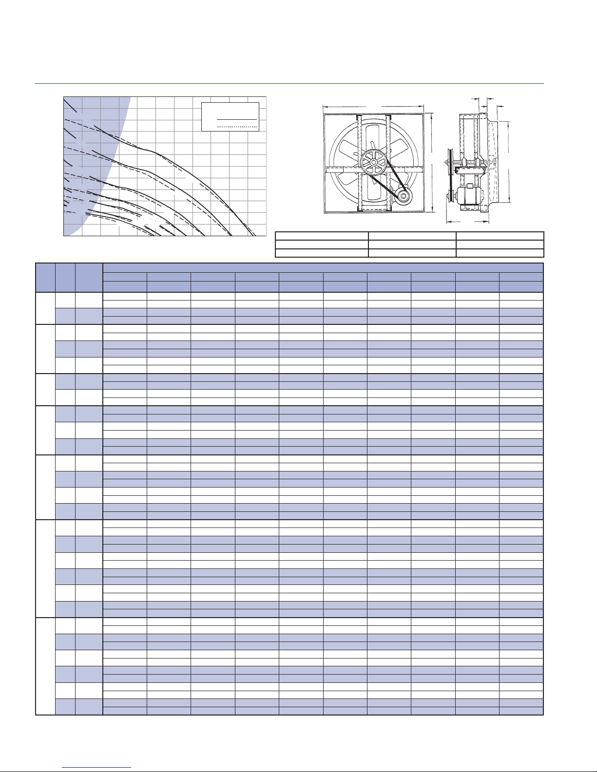
BCH 42 - Belt Drive Fan Data
Breezeway
2.400
2.200
1114 RPM
2.000
1.800
990 RPM
1.600
1.400
833 RPM
1.200
1.000
0.800
0.600
STATIC PRESSURE - Inches W.G.
0.400
0.200
0.000
HP RPM
460 5058
3/4
535 5883
540 5938
1
565 6212
573 6300
580 6377
1 1/2
659 7246
670 7367
2
700 7697
727 7994
740 8137
760 8357
3
790 8687
833 9159
840 9236
880 9676
900 9896
5
930 10226
960 10556
990 10886
1000 10996
1020 11215
1040 11435
7 1/2
1070 11765
1095 12040
1114 12249
535 RPM
0
727 RPM
659 RPM
573 RPM
SPEED
(FPM)
1 1/2 HP
1 HP
3/4 HP
120006000
AIR FLOW - CFM
TIP
0.000" SP 0.100" SP 0.125" SP 0.200" SP 0.250" SP 0.375" SP 0.500" SP 0.625" SP 0.750" SP 1.000" SP
Sones BHP Sones BHP Sones BHP Sones BHP Sones BHP Sones BHP Sones BHP Sones BHP Sones BHP Sones BHP
12749 10762 10220 7903 5659
12.8 0.51 12.2 0.54 12.0 0.55 11.5 0.55 11.5 0.53
14828 13175 12709 11145 9817 4583
16.9 0.80 16.4 0.84 16.2 0.85 15.7 0.87 15.3 0.86 15.3 0.81
14967 13333 12871 11341 10051 4956
17.2 0.82 16.6 0.86 16.5 0.87 16.0 0.89 15.6 0.89 15.6 0.83
15660 14114 13676 12307 11143 7102
18.3 0.94 17.8 0.98 17.7 0.99 17.2 1.02 16.8 1.02 16.9 0.98
15881 14357 13932 12613 11464 7869
18.7 0.98 18.2 1.02 18.1 1.03 17.6 1.06 17.2 1.06 17.2 1.03
16075 14570 14155 12864 11744 8249
19.0 1.02 18.6 1.06 18.4 1.07 17.9 1.10 17.5 1.10 17.5 1.07
18265 16940 16609 15498 14740 12200 8897
23 1.49 23 1.54 23 1.55 22 1.59 22 1.61 21 1.62 22 1.56
18570 17267 16941 15857 15112 12710 9540
23 1.57 23 1.62 23 1.63 23 1.66 22 1.69 21 1.70 23 1.65
19401 18154 17842 16828 16115 13970 11132 6610
25 1.79 25 1.84 25 1.86 24 1.89 24 1.91 23 1.94 23 1.91 28 1.82
20150 18949 18648 17693 17006 15042 12481 8914
25 2.01 24 2.06 24 2.07 24 2.11 23 2.13 23 2.17 22 2.16 24 2.08
20510 19330 19035 18107 17432 15552 13101 10174
24 2.11 24 2.17 24 2.18 23 2.22 23 2.25 23 2.29 22 2.28 23 2.21
21064 19915 19628 18740 18083 16328 14043 11251
25 2.29 24 2.35 24 236 24 2.40 24 2.43 23 2.48 23 2.48 23 2.42
21896 20791 20514 19683 19051 17472 15393 12830 9083
26 2.57 26 2.63 26 2.65 25 2.69 25 2.71 24 2.78 23 2.79 23 2.75 24 2.66
23088 22039 21777 20991 20423 18925 17114 14915 12350
29 3.02 28 3.08 28 3.09 27 3.14 27 3.17 26 3.23 24 3.27 24 3.25 24 3.19
23282 22242 21982 21203 20645 19160 17390 15245 12722
30 3.09 29 3.16 29 3.17 28 3.22 27 3.25 26 3.31 25 3.35 24 3.34 24 3.28
24391 23398 23150 22406 21905 20487 18948 17078 14785 7958
32 3.56 31 3.62 31 3.64 30 3.69 29 3.72 28 3.79 27 3.84 26 3.86 25 3.82 24 3.60
24945 23975 23732 23004 22519 21144 19714 17887 15745 9429
33 3.80 32 3.87 32 3.89 31 3.94 30 3.97 29 4.04 28 4.11 26 4.13 26 4.10 25 3.90
25776 24837 24603 23898 23429 22121 20780 19082 17161 12375
34 4.20 33 4.27 33 4..28 32 4.34 32 4.37 30 4.44 29 4.52 27 4.55 27 4.54 26 4.38
26608 25698 25471 24789 24334 23090 21791 20260 18546 14161
36 4.62 3`5 4.69 34 4.71 34 4.76 33 4.79 32 4.87 30 4.95 29 4.99 28 5.01 27 4.88
27439 26557 26337 25675 25234 24052 22792 21420 19758 15746
37 5.06 36 5.14 36 5.16 35 5.21 34 5.25 33 5.33 32 5.41 30 5.47 29 5.49 28 5.40
27717 26843 26625 25970 25533 24371 23123 21803 20158 16266
38 5.22 37 5.29 36 5.31 35 5.37 35 5.40 33 5.49 32 5.57 30 5.63 29 5.66 29 5.58
28271 27415 27201 26559 26131 25007 23783 22560 20953 17259
39 5.54 37 5.61 37 5.63 36 5.69 36 5.73 34 5.82 33 5.89 31 5.97 30 6.00 29 5.95
28825 27986 27776 27146 26726 25640 24440 23240 21739 18218
40 5.87 38 5.95 38 5.97 37 6.02 37 6.06 35 6.15 34 6.24 32 6.32 31 6.35 30 6.32
29657 28841 28637 28025 27616 26584 25418 24252 22906 19635
41 6.39 40 6.47 39 6.49 39 6.55 38 6.59 37 6.69 35 6.77 34 6.85 32 6.91 31 6.91
30350 29552 29353 28755 28356 27359 26227 25088 23868 20798
42 6.85 41 6.93 41 6.95 40 7.01 39 7.05 38 7.16 36 7.24 35 7.33 33 7.40 31 7.43
30876 30092 29896 29309 28917 27937 26839 25719 24592 21638
43 7.21 42 7.30 42 7.32 41 7.38 40 7.42 39 7.52 37 7.61 36 7.70 34 7.78 32 7.83
7 1/2 HP
5 HP
3 HP
2 HP
18000
Performance shown is for installation Type A: Free Inlet, Free Outlet. Power rating (BHP) does not include drive losses. The sound ratings shown are for loudness values
in fan sones at 5'0" (1.5m) in a hemispherical free fi eld per AMCA standard 301. Values shown are for installation Type A: Free inlet fan sone levels. Performance ratings
do not include the effects of appurtenances in the airstream. For further information on sound classifi cation, see page 40. For accessories, see pages 3 thru 7.
PENNBARRY
36
Do not select shaded area.
RPM
BHP
24000 30000
FAN CAPACITY - CUBIC FEET PER MINUTE (CFM)
3
/
3
46
46
Carbon Steel Panel = 16 gauge Wall Opening = 46 3/4 in.sq. Peak BHP = (RPM/676)^3
Carbon Stl. Mtr. Plate = 10 gauge Wall Shutter ID = 46 in.sq. Max RPM = 1114 (7.5 HP)
Carbon Steel Tube = 16 gauge Est. Shipping Weight = 215 lbs. Max. Motor Frame Size = 184T
4
22
2
41/
43
Page 38

Belt Drive Fan Data - BCH 48
Breezeway
2.400
2.200
1049 RPM
2.000
1.800
962 RPM
1.600
1.400
840 RPM
1.200
707 RPM
1.000
0.800
616 RPM
559 RPM
0.600
486 RPM
0.400
STATIC PRESSURE - Inches W.G.
0.200
0.000
0 8000 16000 24000 32000 40000
TIP
HP RPM
400 5027
1
440 5529
486 6107
490 6158
1 1/2
525 6597
559 7025
570 7163
2
600 7540
616 7741
620 7791
3
660 8294
707 8884
710 8922
770 9676
5
810 10179
840 10556
850 10681
890 11184
910 11435
7 1/2
950 11938
962 12089
970 12189
990 12441
1015 12755
10
1035 13006
1049 13182
SPEED
(FPM)
0.000" SP 0.100" SP 0.125" SP 0.200" SP 0.250" SP 0.375" SP 0.500" SP 0.625" SP 0.750" SP 1.000" SP
Sones BHP Sones BHP Sones BHP Sones BHP Sones BHP Sones BHP Sones BHP Sones BHP Sones BHP Sones BHP
9.9 0.56 9.9 0.59 9.9 0.59 9.5 0.57 9.2 0.54
15.0 0.74 15.4 0.78 14.4 0.79 15.8 0.78 15.8 0.74
14.2 1.00 14.2 1.04 14.2 1.05 14.2 1.06 14.0 1.04
14.5 1.02 14.5 1.07 14.5 1.08 14.5 1.09 14.2 1.07 13.0 0.99
16.8 1.26 16.7 1.31 16.6 1.32 16.7 1.34 16.8 1.33 15.5 1.23
19.4 1.52 19.2 1.57 19.1 1.58 18.9 1.62 19.5 1.62 19.0 1.55
20 1.61 20 1.66 20 1.68 19.8 1.71 20 1.72 20 1.66 19.4 1.55
23 1.87 22 1.93 22 1.95 22 1.99 22 2.00 23 1.96 22 1.82
24 2.03 24 2.09 24 2.10 24 2.15 23 2.16 24 2.14 24 2.02
25 2.07 24 2.13 24 2.14 24 2.19 24 2.21 25 2.18 25 2.08
29 2.49 28 2.56 28 2.58 28 2.62 28 2.65 29 2.66 29 2.58 29 2.41
32 3.06 31 3.14 30 3.15 30 3.20 29 3.24 29 3.28 30 3.23 29 3.12 29 2.95
32 3.10 31 3.18 31 3.19 30 3.24 29 3.28 29 3.32 30 3.27 29 3.16 28 2.98
35 3.96 34 4.04 34 4.06 33 4.11 32 4.15 31 4.23 30 4.22 29 4.14 29 4.01
37 4.61 36 4.69 36 4.71 35 4.77 34 4.81 32 4.90 31 4.93 30 4.87 29 4.77 27 4.44
39 5.14 38 5.23 37 5.25 36 5.31 36 5.35 34 5.44 32 5.49 31 5.47 31 5.37 29 4.97
40 5.33 38 5.41 38 5.43 37 5.50 36 5.54 35 5.63 33 5.69 32 5.67 31 5.58 29 5.18
42 6.11 41 6.20 40 6.23 39 6.29 39 6.34 37 6.44 35 6.52 33 6.53 33 6.47 32 6.20
43 6.54 42 6.63 42 6.65 40 6.72 40 6.76 38 6.87 36 6.96 34 6.99 34 6.94 33 6.69
46 7.44 44 7.53 44 7.56 43 7.63 42 7.67 40 7.79 38 7.89 36 7.94 35 7.93 35 7.73
46 7.72 45 7.82 45 7.84 43 7.92 43 7.96 41 8.08 39 8.18 37 8.25 36 8.24 35 8.05
47 7.91 45 8.01 45 8.04 44 8.11 43 8.16 41 8.27 39 8.38 37 8.45 36 8.45 35 8.27
48 8.41 47 8.52 46 8.54 45 8.62 44 8.66 42 8.78 40 8.89 39 8.98 37 9.00 36 8.84
50 9.07 48 9.17 48 9.20 47 9.27 46 9.32 44 9.45 42 9.56 40 9.67 38 9.70 37 9.58
51 9.61 50 9.72 49 9.75 48 9.83 47 9.88 45 10.00 43 10.12 41 10.23 39 10.27 38 10.19
52 10.01 51 10.12 50 10.14 49 10.22 48 10.28 46 10.40 44 10.52 42 10.63 40 10.69 38 10.63
2 HP
1 1/2 HP
1 HP
AIR FLOW - CFM
16306 13155 12208 8806 3537
17936 15132 14335 11467 9128
19811 17327 16629 14313 12435
19974 17514 16824 14541 12696 4341
21401 19137 18509 16477 14930 8629
22787 20693 20102 18259 16890 12841
23236 21188 20613 18825 17507 13573 5388
24459 22521 21995 20312 19111 15541 8970
25111 23228 22726 21096 19948 16573 11910
25274 23404 22909 21290 20156 16830 12683
26905 25159 24700 23220 22176 19286 15793 8604
28820 27203 26775 25424 24474 21930 18861 15556 7493
28943 27333 26907 25563 24619 22090 19054 15793 7796
31389 29921 29527 28328 27470 25238 22721 19765 16597
33019 31627 31260 30138 29332 27243 24976 22338 19453 8006
34242 32900 32554 31472 30715 28716 26577 24204 21423 11532
34650 33323 32984 31915 31173 29204 27104 24780 22074 12914
36280 35014 34697 33679 32997 31137 29188 27051 24641 19252
37096 35857 35547 34557 33891 32091 30202 28165 25901 20780
38726 37539 37243 36306 35668 33969 32181 30286 28223 23428
39216 38043 37750 36828 36198 34529 32770 30915 28904 24218
39542 38379 38089 37176 36551 34902 33161 31333 29355 24741
40357 39218 38933 38045 37433 35830 34135 32372 30476 26038
41376 40265 39987 39128 38531 36984 35344 33647 31821 27646
42191 41102 40830 39992 39406 37903 36305 34641 32878 28916
42762 41687 41419 40596 40018 38544 36971 35333 33614 29797
3 HP
5 H
7 1/2 HP
P
Performance shown is for installation Type A: Free Inlet, Free Outlet. Power rating (BHP) does not include drive losses. The sound ratings shown are for loudness values
in fan sones at 5'0" (1.5m) in a hemispherical free fi eld per AMCA standard 301. Values shown are for installation Type A: Free inlet fan sone levels. Performance ratings
do not include the effects of appurtenances in the airstream. For further information on sound classifi cation, see page 40. For accessories, see pages 3 thru 7.
Do not select shaded area.
RPM
BHP
10 HP
54
Carbon Steel Panel = 16 gauge Wall Opening = 55 in.sq. Peak BHP = (RPM/555)^3
Carbon Stl. Mtr. Plate = 10 gauge Wall Shutter ID = 54 in.sq. Max RPM = 1049 (10 HP)
Carbon Steel Tube = 16 gauge Est. Shipping Weight = 295 lbs. Max. Motor Frame Size = 286T
FAN CAPACITY - CUBIC FEET PER MINUTE (CFM)
3
4
2
/
54
25
4
4 3/
49
PENNBARRY
37
Page 39

BCH 54 - Belt Drive Fan Data
Breezeway
2.600
2.400
2.200
2.000
1.800
1.600
1.400
1.200
1.000
0.800
0.600
STATIC PRESSURE - Inches W.G.
0.400
0.200
0.000
HP RPM
1
1 1/2
2
3
5
7 1/2
10
15
1074 RPM
959 RPM
870 RPM
759 RPM
639 RPM
557 RPM
505 RPM
440 RPM
0 8000 16000
TIP
SPEED
(FPM)
300 4241
340 4807
440 6220
450 6362
505 7139
510 7210
557 7874
560 7917
639 9034
650 9189
700 9896
759 10730
770 10886
820 11592
870 12299
880 12441
900 12723
920 13006
940 13289
959 13558
970 13713
990 13996
1010 14279
1030 14561
1050 14844
1074 15183
15
HP
10 HP
7 1/2 HP
5 HP
3 HP
1 1/2 HP
2 HP
1 HP
24000
32000 40000
AIR FLOW - CFM
0.000" SP 0.100" SP 0.125" SP 0.200" SP 0.250" SP 0.375" SP 0.500" SP 0.625" SP 0.750" SP 1.000" SP
Sones BHP Sones BHP Sones BHP Sones BHP Sones BHP Sones BHP Sones BHP Sones BHP Sones BHP Sones BHP
15731 10711 8686
8.5 0.33 7.5 0.34 7.4 0.333
17828 13961 12337
10.7 0.47 9.8 0.49 9.4 0.49
23072 20334 19647 16439 13927
16.9 1.03 16.2 1.05 16.0 1.05 15.1 1.07 14.7 1.05
23596 20918 20252 17268 14922
17.6 1.10 16.8 1.12 16.6 1.12 15.8 1.14 15.3 1.12
26480 24108 23498 21572 19462 13255
21 1.55 20 1.58 19.9 1.58 19.3 1.59 18.9 1.61 18.0 1.52
26743 24397 23789 21945 19872 13984
21 1.0 20 1.62 20 1.63 19.6 1.64 19.2 1.65 18.3 1.58
29207 27083 26515 24879 23548 18852
26 2.08 25 2.11 25 2.12 24 2.13 23 2.14 23 2.14
29365 27253 26688 25062 23773 19101
26 2.11 25 2.14 25 2.15 24 2.16 24 2.17 24 2.17
33507 31696 31201 29735 28796 25495 21360
37 3.14 37 3.16 37 3.18 35 3.21 34 3.21 34 3.24 36 3.22
34084 32309 31822 30375 29452 26371 22322 16821
37 3.30 37 3.33 37 3.34 35 3.38 34 3.38 34 3.41 35 3.40 34 3.22
36706 35075 34631 33276 32403 30173 26351 22451
37 4.13 36 4.15 36 4.16 35 4.21 34 4.22 32 4.23 32 4.29 32 4.22
39800 38296 37916 36666 35833 33840 31118 27481 23812
37 5.26 35 5.28 35 5.29 34 5.34 33 5.37 32 5.38 30 5.42 29 5.49 28 5.36
40376 38894 38524 37293 34672 34512 31962 28407 24912
37 5.49 36 5.52 35 5.52 34 5.57 34 5.61 32 5.61 31 5.65 30 5.72 29 5.62
42998 41607 41259 40129 39357 37490 35590 32519 29211 20950
40 6.63 39 6.66 38 6.66 37 6.71 36 6.75 35 6.78 33 6.80 32 6.86 31 6.89 29 6.45
45620 44308 43981 42941 42214 40426 38682 36426 33323 26849
43 7.92 42 7.95 41 7.96 40 7.99 39 8.03 38 8.10 36 8.10 35 8.15 34 8.22 33 8.04
46145 44848 44524 43501 42782 41009 39295 37180 34145 27855
44 8.20 42 8.23 42 8.23 41 8.27 40 8.31 38 8.38 36 8.38 35 8.43 34 8.49 33 8.36
47193 45925 45608 44619 43916 42171 40504 38678 35762 29844
45 8.77 44 8.80 43 8.80 42 8.84 41 8.88 39 8.96 37 8.96 36 9.00 35 9.06 34 8.99
48242 47002 46691 45734 45047 43328 41697 39992 37354 31628
47 9.37 45 9.40 45 9.40 43 9.43 42 9.47 40 9.58 39 9.58 37 9.61 36 9.66 35 9.66
49291 48077 47773 46847 46174 44492 42884 41234 38913 33197
48 9.99 46 10.02 46 10.03 45 10.06 44 10.10 42 10.20 40 10.21 38 10.24 37 10.29 36 10.36
50287 49097 48800 47901 47242 45593 44007 42407 40353 34671
49 10.61 47 10.64 47 10.65 46 10.67 45 10.71 43 10.82 41 10.85 39 10.86 38 10.91 37 11.07
50864 49687 49393 48511 47859 46229 44654 43083 41181 35599
50 10.98 48 11.01 48 11.02 46 11.04 45 11.08 43 11.19 41 11.22 40 11.23 38 11.28 37 11.4
51913 50760 50472 49607 48979 47382 45827 44307 42675 37271
51 11.67 49 11.70 49 11.71 48 11.73 47 11.77 44 11.88 42 11.93 41 11.93 39 11.98 38 12.13
52961 51831 51549 50702 50096 48531 46996 45510 43945 38924
52 12.40 50 12.43 50 12.43 49 12.46 48 12.49 46 12.60 44 12.67 42 12.67 40 12.71 39 12.85
54010 52902 52625 51794 51211 49676 48159 46703 45187 40553
54 13.15 52 13.18 51 13.19 50 13.21 49 13.24 47 13.35 45 13.44 43 13.44 41 13.47 40 13.60
55059 53972 53700 52885 52323 50817 49318 47890 46422 42154
55 13.93 53 13.96 53 13.97 52 13.99 51 14.02 48 14.13 46 14.24 44 14.24 42 14.26 41 14.38
56317 55255 54989 54192 53655 52183 50711 49307 47895 44056
57 14.91 55 14.94 55 14.94 53 14.97 52 14.99 50 15.11 48 15.22 46 15.23 44 15.24 42 15.35
Performance shown is for installation Type A: Free Inlet, Free Outlet. Power rating (BHP) does not include drive losses. The sound ratings shown are for loudness values
in fan sones at 5'0" (1.5m) in a hemispherical free fi eld per AMCA standard 301. Values shown are for installation Type A: Free inlet fan sone levels. Performance ratings
do not include the effects of appurtenances in the airstream. For further information on sound classifi cation, see page 40. For accessories, see pages 3 thru 7.
PENNBARRY
38
Do not select shaded area.
RPM
BHP
48000 56000
FAN CAPACITY - CUBIC FEET PER MINUTE (CFM)
60
60
Carbon Steel Panel = 16 gauge Wall Opening = 61 in.sq. Peak BHP = (RPM/416)^3
Carbon Stl. Mtr. Plate = 10 gauge Wall Shutter ID = 60 in.sq. Max RPM = 1074 (15 HP)
Carbon Steel Tube = 16 gauge Est. Shipping Weight = 335 lbs. Max. Motor Frame Size = 286T
3
5
55
28
Page 40

Belt Drive Fan Data - BCH 60
Breezeway
3.200
3.000
2.800
780 RPM
2.600
721RPM
2.400
2.200
2.000
1.800
1.600
571 RPM
1.400
1.200
1.000
0.800
0.600
STATIC PRESSURE - Inches W.G.
0.400
0.200
0.000
HP RPM
1 1/2
2
3
5
7 1/2
10
15
20
629 RPM
498 RPM
419 RPM
365 RPM
331 RPM
0
TIP
SPEED
(FPM)
241 3786
270 4241
331 5199
340 5341
365 5733
370 5812
419 6582
430 6754
498 7823
510 8011
545 8561
571 8969
580 9111
600 9425
615 9660
629 9880
640 10053
660 10367
680 10681
700 10996
721 11325
730 11467
745 11702
760 11938
775 12174
780 12252
20 HP
15 HP
10 HP
7 1/2 HP
5 HP
2 HP
1 1/2 HP
2000010000 30000 40000 50000
3 H
P
AIR FLOW - CFM
0.000" SP 0.100" SP 0.125" SP 0.200" SP 0.250" SP 0.375" SP 0.500" SP 0.625" SP 0.750" SP 1.000" SP
Sones BHP Sones BHP Sones BHP Sones BHP Sones BHP Sones BHP Sones BHP Sones BHP Sones BHP Sones BHP
21063 15681 13828
10.2 0.59 9.7 0.62 9.8 0.62
23598 18983 17597
12.4 083 11.6 0.86 11.7 0.87
28929 25548 24423 21005 17965
18.0 1.52 16.9 1.57 16.6 1.58 16.7 1.60 17.1 1.60
29716 26485 25389 22081 19435
18.9 1.65 17.8 1.70 17.4 1.71 17.4 1.74 17.7 1.74
31901 28976 28034 24948 22847
21 2.04 20 2.10 20 2.11 19.6 2.14 19.8 2.15
32338 29461 28557 25515 23476
22 2.12 21 2.19 21 2.20 20 2.23 20 2.24
36620 34154 33453 30927 29128 24180
26 3.08 25 3.16 25 3.17 24 3.21 24 3.23 24 3.25
37582 35196 34513 32108 30360 25766
27 3.33 26 3.41 26 3.43 25 3.47 24 3.49 24 3.52
43525 41530 40977 39208 37731 33957 29964 18028
33 5.18 31 5.27 31 5.29 30 5.35 30 5.37 28 5.43 27 5.47 25 5.38
44574 42626 42105 40378 38997 35318 31527 24750
34 5.56 33 5.65 32 5.68 31 5.74 31 5.77 29 5.83 28 5.87 27 5.75
47632 45810 45354 43761 42643 39218 35774 31807 19636
37 6.78 36 6.89 35 6.91 34 6.98 34 7.02 32 7.09 30 7.15 30 7.16 28 7.06
49905 48165 47731 46250 45222 42053 38752 35350 30653
39 7.80 38 7.91 38 7.94 37 8.01 36 8.05 34 8.13 32 8.19 31 8.24 31 8.20
50692 48979 48551 47108 46095 43022 39775 36488 32359
40 8.18 39 8.29 38 8.31 37 8.38 37 8.43 35 8.51 33 8.58 32 8.63 31 8.62
52440 50784 50370 49007 48028 45159 42030 38914 35274
42 9.05 40 9.16 40 9.19 39 9.27 38 9.31 37 9.41 34 9.48 33 9.54 33 9.56
53751 52135 51732 50426 49471 46748 43703 40651 37385
43 9.75 42 9.86 41 9.89 40 9.97 40 10.02 38 10.12 36 10.19 34 10.26 34 10.30
54974 53395 53000 51745 50812 48221 45251 42257 39168 22607
44 10.43 43 10.55 43 10.58 42 10.66 41 10.71 39 10.81 37 10.89 35 10.96 34 11.02 33 10.86
55936 54384 53996 52780 51862 49373 46459 43508 40554 27400
45 10.99 44 11.11 44 11.14 43 11.22 42 11.27 40 11.38 38 11.46 36 11.54 35 11.60 34 11.23
57684 56179 55802 54655 53765 51453 48631 45775 42946 35529
47 12.05 46 12.17 45 12.20 44 12.29 44 12.34 42 12.47 39 12.55 37 12.63 36 12.70 36 12.67
59432 57971 57606 56510 55660 53501 50779 48017 45256 38871
49 13.18 47 13.30 47 13.34 46 13.43 45 13.48 44 13.62 41 13.71 39 13.79 37 13.86 37 13.91
61180 59761 59406 58342 57548 55450 52907 50234 47537 41763
51 14.37 49 14.50 49 14.54 48 14.64 47 14.69 45 14.83 43 14.93 41 15.02 39 15.10 38 15.19
63015 61637 61293 60260 59522 57486 55124 52539 49919 44554
53 15.71 52 15.84 51 15.88 50 15.98 50 16.04 48 16.18 45 16.29 43 16.38 41 16.47 39 16.59
63802 62441 62101 61080 60366 58355 56068 53517 50932 45694
54 16.30 53 16.44 53 16.47 51 16.58 51 16.64 49 16.78 47 16.90 44 16.99 42 17.08 40 17.22
65112 63779 63446 62446 61770 59800 57636 55136 52610 47579
56 17.33 55 17.47 55 17.50 54 17.61 53 17.68 51 17.82 49 17.95 47 18.04 44 18.13 42 18.29
66424 65117 64790 63810 63156 61239 59195 56744 54276 49345
59 18.40 57 18.54 57 18.57 56 18.68 55 18.75 53 18.90 51 19.04 49 19.13 46 19.23 43 19.39
67735 66453 66133 65171 64531 62675 60746 58343 55931 51083
61 19.51 59 19.65 59 19.69 58 19.80 57 19.87 55 20.02 53 20.17 51 20.27 49 20.37 45 20.54
68172 66898 66580 65625 64988 63152 61262 58874 56480 51660
62 19.89 60 20.03 60 20.07 59 20.18 58 20.25 56 20.41 54 20.56 52 20.66 49 20.76 45 20.93
Performance shown is for installation Type A: Free Inlet, Free Outlet. Power rating (BHP) does not include drive losses. The sound ratings shown are for loudness values
in fan sones at 5'0" (1.5m) in a hemispherical free fi eld per AMCA standard 301. Values shown are for installation Type A: Free inlet fan sone levels. Performance ratings
do not include the effects of appurtenances in the airstream. For further information on sound classifi cation, see page 40. For accessories, see pages 3 thru 7.
Do not select shaded area.
RPM
BHP
60000
66
Carbon Steel Panel = 16 gauge Wall Opening = 67 in.sq. Peak BHP = (RPM/246)^3
70000
Carbon Stl. Mtr. Plate = 10 gauge Wall Shutter ID = 66 in.sq. Max RPM = 780 (20 HP)
Carbon Steel Tube = 16 gauge Est. Shipping Weight = 420 lbs. Max. Motor Frame Size = 286T
FAN CAPACITY - CUBIC FEET PER MINUTE (CFM)
3
4
/
2
66
28
6
61
PENNBARRY
39
Page 41

Sound Data Notes
Breezeway
Sound Power Levels
Since any mechanical device generates some sound energy
into the air, fans will create some noise. Because of the great
number of factors infl uencing sound output it is invalid to
compare fans based on RPM, tip speed or outlet velocity. The
only accurate basis of comparison is the sound power level
generated by the fan at the required point of operation.
Having sound power levels for a specifi c fan at a specifi c
operating point allows the system designer to determine the
theoretical sound pressure level at any point in the occupied
space. AMCA Publication 303 and the ASHRAE Guides
provide more information on this process. Another typical
application of sound power levels is to compare similar fans.
Generally differences of 6 dB in the 63 Hz band and 3 dB in
all other bands are considered insignifi cant.
System designers use many methods to predict acoustic
acceptability of an occupied space.
The A-weighted sound pressure level provides a single
number that corresponds well to the human judgement of
relative loudness. OSHA bases their requirements regarding
exposure to noise on A-weighted sound pressure levels. The
disadvantage of this method is that A-weighted sound pressure
levels do not provide information as to the quality of the sound.
Noise Criteria (NC) curves are also widely used. To determine
the NC level, the sound power spectrum is compared to
defi ned limits. Other methods include RC curves, Sones, SIL
and Noise Rating Curves.
Each method relies on sound pressure level information
because the human ear “hears” sound pressure fl uctuations,
not sound power (watts). Sound pressure is a function of the
attenuation of the space and the distance from the source.
Consider a 100 watt light bulb. It provides adequate light for
a closet, but not for a classroom, and in a stadium it would
be imperceptible. While the light source was the same power
(100 watts), the brightness level changed dramatically.
Similarly, the same sound power level (acoustical energy)
produces greatly different sound pressure levels (noise).
Sound power levels shown in this catalog were measured
and certifi ed using AMCA standard 300 Reverberant Room
Method for Sound Testing of Fans. The values shown are for
the eight octave bands defi ned in this standard, which agree
with ANSI 61.11-1986. One-third octave band sound power
levels shown are rated in decibels (dB) using 10-12 watts as
a reference.
Sone Ratings
In addition to sound power levels, PennBarry has provided
sone ratings to allow designers to make an educated judgment
as to the noise level a fan will develop in a space. Sone
ratings are a loudness index developed from sound power
level data. The calculation is at 5’ from the fan inlet and in
front of a refl ecting plane (hard wall). Sones are weighted
similarly to the A-weighting scale in that more weight is given
to frequencies that people can hear “well” and less weight to
frequencies that people do not hear “well”. A signifi cant feature
of the sone scale is that it is linear rather than logarithmic.
This means that 40 sones is 33% louder than 30 sones, as
opposed to 40 dB being twice as loud as 30 dB.
Since the sone rating is determined from well defined
assumptions and is linear in nature, it is ideal for comparing
different fans moving air at the same CFM and SP. When using
sones for this purpose, differences of 3 sones are considered
negligible. The suggested loudness level chart below is a
practical guideline for acceptable installed performance.
The sone values shown in this catalog are based on the sound
power levels determined above, and calculated in accordance
with AMCA Standard 301 “Methods for Calculating Fan Sound
Ratings from Laboratory Test Data.”
Sound Classifi cation Guide
SUGGESTED LOUDNESS LEVEL
AREA SONE
LEVEL
Up to 9 32 to 54 35 to 60
9.1 to 13 55 to 59 61 to 65
13.1 to 18 60 to 64 66 to 70
18.1 to 50 65 to 78 71 to 84
50.1 Plus 78.1 to 85+
Notes: (1) dBA range of A-weighted sound levels, in decibels.
PENNBARRY
40
NOISE
CRITERIA NCdBA (1) TYPES OF AREAS
Bingo Hall, Auction Room, Hotel Ballroom, Social Club, Reception Room, Apartment House, Professional Offi ce, Supervisor Offi ce,
Lobby/Corridor, Spectator Area, Chicken House, Greenhouse, General Open Offi ce, Restaurant, Night Club, Department Store, Ticket
Sales Offi ce, Casino, Spa, Control Room, Rail, Bus, Plane, Bowling Alley, Print Shop, Drafting Offi ce, Convention Hall
Washroom & Toilet, Retail Shop, Bus Terminal Lounge, Foreman’s Offi ce, Cocktail Lounge, Offi ce Hall & Corridor, Tabulation &
Computation Offi ce, Kitchen Cafeteria, Hotel Garage, Computer Room, Warehouse, Battery Charging Room
General Storage Area, Restaurant Banquet Room, Swimming Pool, Supermarket, Hotel Kitchen and Laundry, Welding Booth,
84.1 to
90+ (2)
Manufacturing Area, Heavy Machine Foundry, Assembly Line, Machine Shops, Punch Press Shop, Light Machine Area, Boiler Room,
Emergency Generator Room, Pump House, Power Plant, Transformer, Steel Mill, Engine Test Room, Compressor Room, Steel Stamping
Courtroom, School and Classroom, Hospital Ward, Operating Room, Correction Facility.
Department Store Main Floor, Paint Booth, Heat Treating Plant, Tool Maintenance Area
(2) Sound levels this high subject to OSHA Standards for safety, as well as state
and local ordinances. Sound attenuation provisions should be considered.
Source: ASHRAE, AMCA Publications
Moderately
Quiet Sound
Average
Commercial
High Sound
Ext. Heavy
Industrial
Page 42
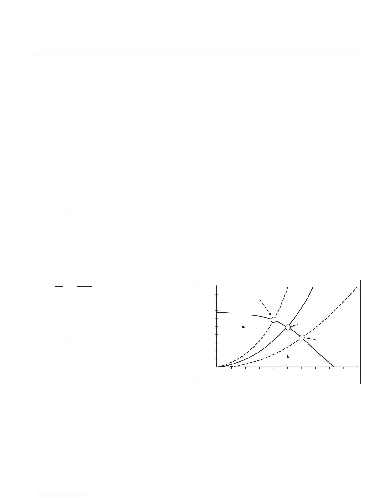
Engineering Notes
Breezeway
Fan Laws
The following section includes engineering and technical data,
guidelines and system explanations related to air moving
and control devices. Fan laws and system descriptions are
consistent with industry standards, defi nitions and accepted
practices. This information is provided to assist system
designers in sizing, selecting and defi ning their air moving
and control systems as well as explaining variables inherent
in system design.
There are nine fan laws, three are of prime importance to the
understanding of ventilation systems. These, together with an
appreciation of fan types, should help avoid most problems
with poor airfl ow performance. These three laws assume the
same fan operating with air at a constant density.
1. Airfl ow and fan speed are directly proportional.
CFM
CFM
CFM1 is the original fl ow rate in cu. ft. per minute.
CFM2 is the desired fl ow rate in cu. ft. per minute.
RPM1 is the original rotational speed of the fan.
RPM2 is the desired rotational speed of the fan.
RPM
RPM
2
1
2
=
1
Interaction of Fan Curves and System Curves
A ventilation system using a Breezeway may consist of a fan
with duct connected to the inlet side. Control dampers, grilles,
registers and duct fi ttings may also be part of the system.
The fan is the component in the system which provides
energy to the airstream to overcome the resistance to fl ow
off the other components. The determination of the “pressure
loss” or “resistance to fl ow”, for the individual components
can be obtained from the component manufacturers. The
determination of pressure losses for ductwork and branch
ductwork design is well documented in standard handbooks,
such as the ASHRAE Handbook of Fundamentals.
The fan curve shown in Figure 1 is a typical fan performance
curve, developed through the actual testing of a fan in an
air tunnel. The fan is run at constant speed and constant air
density. When the fan is installed in the fi eld, then it becomes
part of the system. System curves are developed by using fi eld
tested data and applying fan laws. The point of intersection of
the system curve and the fan performance curve determines
the actual fl ow volume. If the system resistance has been
accurately determined, and the fan properly selected, the
performance curves will intersect at the system design point
(point A).
2. Pressure varies as the square of the fan speed
or airfl ow.
P
P
RPM
2
=
[
RPM
1
2
2
]
1
P1 is the original static pressure.
P2 is the desired static pressure.
3. Power varies as the cube of fan speed.
BHP
BHP
RPM
2
=
[
RPM
1
3
2
]
1
Figure 1
Interaction of System Curves and Fan Curve
UNDER ESTIMATED S.P.
RESULTS IN HIGH STATIC
LOW C.F.M.
FAN CURVE
B
0
200 400 600 800 1000 1200 1400 1600 1800 2000
DUCT SYSTEM A
A
CFM
SYSTEM
DESIGN
POINT
C
Static Pressure - Inches W.G.
1.500
1.375
1.125
1.000
0.875
0.750
0.625
0.500
0.375
0.125
OVER ESTIMATED S.P.
RESULTS IN LOW STATIC
HIGH C.F.M.
PENNBARRY
41
Page 43
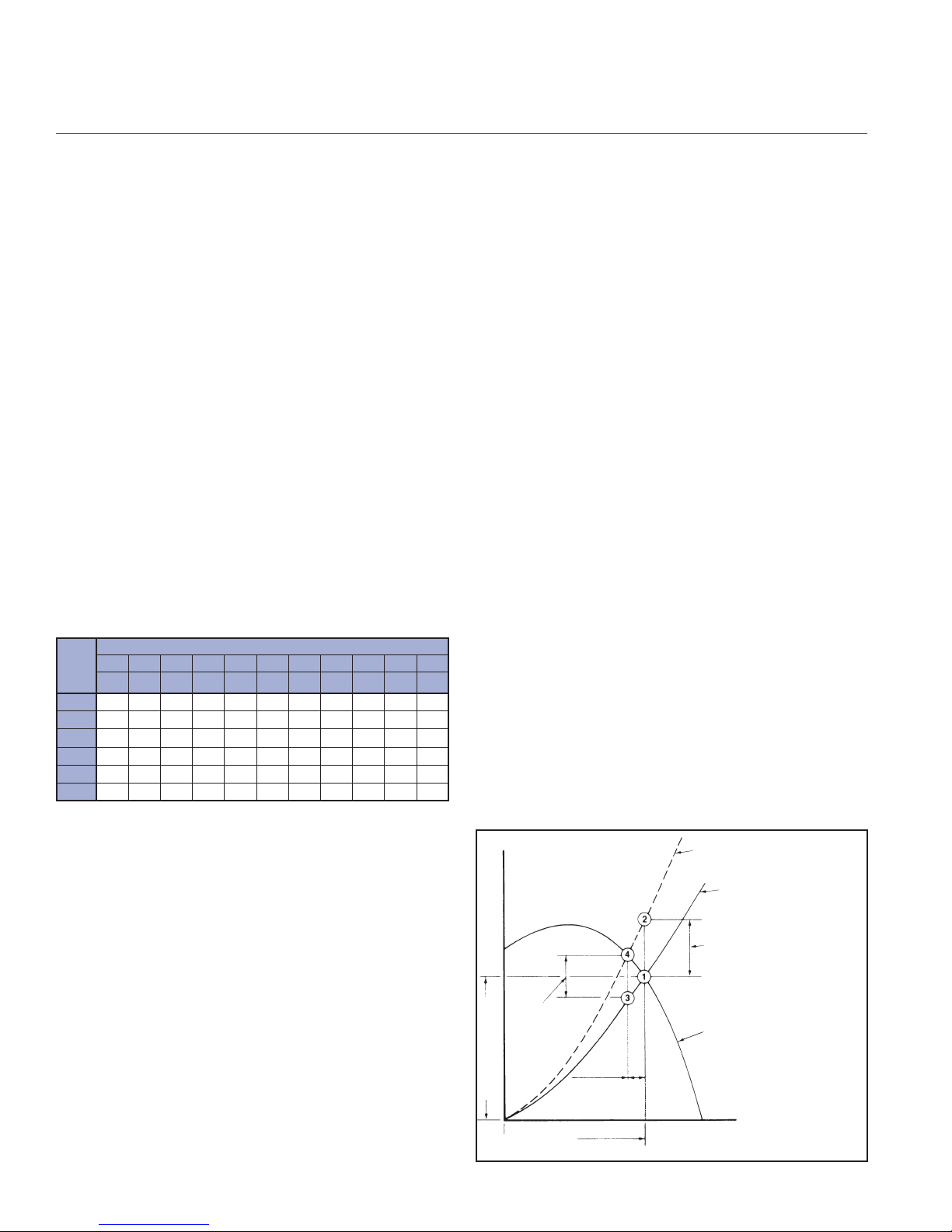
Engineering Notes
Breezeway
If the system resistance has been underestimated, then fan
curves and system curves will not intersect at the system
design point. They will intersect at lower CFM (point B). If the
system resistance has been overestimated, then the fan curve
system curve will intersect at a higher CFM than the system
design point (point C). (See Figure 1)
Effect of Change in Density, Altitude and Temperature
Correction Factors
The resistance of a duct system is dependent upon the density
of the gas fl owing through the system. A gas density of 0.075
3
is standard in the fan industry.
lb/ft
Pressure and horsepower vary directly as the ratio of the gas
density at the fan inlet to standard density. This density ratio
must always be considered when selecting fans. To select
a fan, pressure should be corrected to standard air density,
3
0.075 lb/ft
, 70ºF. at sea level. Static pressure at operating
condition x correction factor=static pressure at standard.
Refer to Table 1.
Table 1
Correction Factors
Unity Basis = Standard Air Density of 0.075 lb/ft
At sea level (29.92 in. Hg barometric pressure) this is equivalent to
dry air at 70°F.
TEMP
ALTITUDE (FEET) WITH BAROMETRIC PRESSURE (Inches Hg)
0' 500' 1000' 1500' 2000' 2500' 3000' 3500' 4000' 4500' 5000'
ºF
29.92 29.38 28.86 28.33 27.82 27.31 26.82 26.32 25.84 25.36 24.9
- 40 0.79 0.81 0.82 0.84 0.85 0.87 0.88 0.9 0.92 0.93 0.95
0 0.87 0.88 0.9 0.92 0.93 0.95 0.97 0.99 1 1.02 1.04
40 0.94 0.96 0.98 1 1.01 1.03 1.05 1.07 1.09 1.11 1.13
70 1 1.02 1.04 1.06 1.08 1.1 1.12 1.14 1.16 1.18 1.2
80 1.02 1.04 1.06 1.08 1.1 1.12 1.14 1.16 1.18 1.2 1.22
100 1.06 1.08 1.1 1.12 1.14 1.16 1.18 1.2 1.22 1.25 1.27
Horsepower at standard ÷ correction factor = horsepower at
operating condition. Motors should be sized for highest density
conditions at which it is expected to operate.
3
Inlet System Effect
The most common installation problem is ductwork connection
to the inlet side of the fan. Here are several design criteria
for connecting ductwork to the fan. Keep a straight duct run
twice the diameter of the inlet size immediately before the
inlet of the fan. This will give the air a chance to straighten
out before entering the fan. Fan inlet swirl and non-uniform
inlet fl ow can often be corrected by inlet straightening vanes
or guide vanes. Restricted fan inlets located too close to walls,
obstructions or restrictions caused by a plenum or cabinet, will
decrease the useable performance of a fan. Cabinet clearance
effect or plenum effect must be considered a component
part of the entire system; the pressure losses through the
cabinet or plenum effect is considered as a System Effect
when determining system characteristics. The backdraft
damper is part of external static pressure, and should be
accounted for when estimating system static pressure. Use
a motorized backdraft damper when the fan has a variable
speed controller.
System Effect
A System Effect Factor is a pressure loss which recognizes
the effect of fan inlet restrictions, fan outlet restrictions or other
conditions infl uencing fan performance when installed in the
system. Figure 2 illustrates defi cient fan/system performance
resulting from one or more undesirable fl ow conditions. It is
assumed that the system pressure losses, shown in system
curve A, have been accurately determined, and a suitable fan
selected for operation at Point 1. However, no allowance has
been made for the effect of the system connections on the
fan’s performance. To compensate for this System Effect, it
will be necessary to add a System Effect Factor (SEF) to the
calculated system pressure losses to determine the actual
system curve. The SEF for any given confi guration is velocity
dependent and will, therefore, vary across the range of fl ow
volumes for the fan.
In Figure 2, the point of intersection between the fan
performance curve and the actual system curve B is Point
4. The actual fl ow volume will, therefore, be defi cient by the
difference from 1-4. To achieve design fl ow volume, an SEF
equal to the pressure difference between Point 1 and 2 should
have been added to the calculated system pressure losses and
the fan selected to operate at Point 2. Note that because the
System Effect is velocity related, the difference represented
between Points 1 and 2 is greater than the difference between
Points 3 and 4.
The SEF includes only the effect of the system confi guration
on the fan’s performance.
Figure 2
CURVE B - ACTUAL DUCT
SYSTEM WITH SYSTEM
EFFECT
CURVE A - CALCULATED DUCT
SYSTEM WITH NO ALLOWANCE
FOR SYSTEM EFFECT
SYSTEM EFFECT LOSS AT
DESIGN VOLUME
SYSTEM
EFFECT AT
ACTUAL
FLOW
VOLUME
DESIGN PRESSURE
DESIGN VOLUME
Defi cient Fan/Duct System Performance System Effect Ignored
DEFICIENT
PERFORMANCE
FAN CATALOG
PRESSURE-VOLUME
CURVE
PENNBARRY
42
Page 44

Engineering Notes
Breezeway
Inlet Duct Elbows
Non-uniform fl ow into a fan inlet is the most common cause
of defi cient fan performance. An elbow located at, or in
close proximity to the fan inlet will not allow the air to enter
the impeller uniformly. The result is less than cataloged air
performance.
Inlet Vortex (Spin or Swirl)
Another major cause of reduced performance is an inlet
duct condition that produces a vortex or spin in the airstream
entering a fan inlet.
The ideal inlet condition is one which allows the air to enter
axially and uniformly without spin in either direction. A spin
in the same direction as the impeller rotation (pre-rotation)
reduces the pressure volume curve by an amount dependent
upon the intensity of the vortex. The effect is similar to the
change in the pressure volume curve achieved by inlet vanes
installed in a fan inlet; the vanes induce a controlled spin in the
direction of impeller rotation reducing the volume fl ow rate.
A counter-rotating vortex at the inlet may result in a slight
increase in the pressure-volume curve but the horsepower
will increase substantially.
Inlet Turning Vanes
Where space limitations prevent the use of optimum fan inlet
connections, more uniform fl ow can be achieved by the use
of turning vanes in the inlet elbow.
Numerous variations of turning vanes are available from a
single curved sheet metal vane to multi-bladed “airfoil” vanes.
The pressure drop through these devices must be added to
the system pressure losses.
Spark Resistant Construction
AMCA standards offer the following defi nitions and notes
concerning spark resistant construction:
C – The fan shall be constructed so that a shift in the
impeller or shaft will not permit two ferrous parts of
the fan to rub or strike.
B – The fan shall have a non-ferrous impeller and non-
ferrous ring about the opening through which the
shaft passes. Ferrous hubs, shafts and hardware
are allowed, provided construction is such that a shift
in impeller or shaft will not permit two ferrous parts
of the fan to rub or strike. Steps must also be taken
to insure that the impeller, bearings, and shaft are
adequately attached and/or restrained to prevent a
lateral or axial shift in these components.
Notes: 1) No bearings, drive components or electrical components shall be placed in the air or gas stream unless they are constructed or enclosed in such a manner
that failure of the component cannot ignite the surrounding gas stream.
2) The user shall electrically ground on all fan parts.
3) For this standard, non-ferrous shall be any material with less than 5% iron or any other material with demonstrated ability to be spark resistant.
4) The use of aluminum or aluminum alloys in the presence of steel which has been allowed to rust requires special consideration. Research by the
U.S.Bureau of Mines and others has shown that aluminum impellers rubbing on rusty steel may cause high-intensity sparking.
The use of the above standard in no way implies a guarantee of safety for any level of spark resistance. Spark resistant
construction does not protect against ignition of explosive gases caused by catastrophic failure or from any airstream material
that may be present in a system.
Metric Equivalents
Many PennBarry products are specifi ed and installed overseas. For your convenience,
the table below provides conversion factors from English to Metric.
CATEGORY
VOLUME FLOW CFM 0.00047195 cu. meter per sec. (m3/s)
PRESSURE Inches (wg) 248.36 pascal (Pa or N/m2)
POWER H.P. 745.7 watt (W or J/s)
TEMPERATURE Fahrenheit (°F) (°F + 459.67)/1.8 kelvin
HEAT Btu 1.055 kilojoules (kj)
TIP SPEED Ft/M 0.00508 meter per second (m/s)
SPEED RPM 0.016 rev. per second (rps)
VELOCITY Ft/M 0.00508 meter per second (m/s)
DIMENSIONS
AMCA STANDARD /
ENGLISH UNIT
Inches 25.4 millimeter (mm)
Feet 0.3048 meter (m)
Square Feet 0.0929 square meter (m2)
Cubic Feet 0.0283 cubic meter (m3)
x CONVERSION
FACTOR
= METRIC (SI) UNIT
PENNBARRY
43
Page 45

Sample Specifi cations
Breezeway
P Series
Direct drive Axial Panel exhaust or supply fan shall be
Breezeway P manufactured by PennBarry, Richardson,
Texas. Motors are rigidly mounted on a heavy gauge
wire basket/rear guard of concentric rings meeting OSHA
specifi cation. Vibration isolation is provided between the
motor/guard assembly and a coated steel fan panel featuring
welded corners, pre-punched mounting holes, and a deeply
spun venturi. Statically balanced propellers are die formed
aluminum. Motors shall be continuous duty, multi-speed (for
applicable models) and permanently lubricated. Each fan
shall bear the AMCA Licensed Ratings Seal for Air and Sound
Performance, and shall be UL and CSA Listed.
Breezex
Direct drive Axial Panel exhaust or supply fan shall be
Breezeway BX manufactured by PennBarry, Richardson,
Texas. Motors are installed on a heavy gauge mounting plate
welded to a formed heavy wall tubular frame, welded onto a
coated steel fan panel featuring welded corners, pre-punched
mounting holes, and a deeply spun venturi. Statically balanced
propellers are aluminum. Motors shall be Totally Enclosed
(TE), continuous duty, ball bearing design, include thermal
overload protection and be reversible. A reversing switch shall
be supplied. (Explosion Proof, Cls. 1, Div. 1, Grp. D, optionally
available; reversing switch by others.)
Type BC
Direct drive Axial Panel exhaust or supply fan shall be
Breezeway BC manufactured by PennBarry, Richardson,
Texas. A heavy gauge motor mounting platform is supported
by formed integral stiffening flanges and welded onto a
coated steel fan panel featuring welded corners, pre-punched
mounting holes, and a deeply spun venturi. Statically balanced
propellers shall be cast aluminum and airfoil shaped. Motors
shall be continuous duty, ball bearing design, positively cooled
and furnished at the specifi ed voltage and phase.
Type BLL
Belt driven Axial Panel exhaust fan shall be Breezeway BLL
manufactured by PennBarry, Richardson, Texas. A heavy
gauge motor mounting platform is supported by formed
integral stiffening fl anges and welded onto a coated steel fan
panel featuring welded corners, pre-punched mounting holes,
and a deeply spun venturi. Statically balanced propellers
shall be heavy gage steel. Motors shall be continuous duty,
ball bearing design, and positively cooled, furnished at the
specifi ed voltage, phase, and enclosure. Shafts shall be
turned, ground, polished, & rust protected. Heavy duty ball
bearings are rated for a minimum L50 life exceeding 200,000
hours. Pulleys shall be adjustable, cast iron, machined, keyed,
securely attached and sized for 150% of the horsepower at
its rated maximum speed. Each fan shall bear the AMCA
Licensed Ratings Seal for Air and Sound Performance, and
shall be UL and CSA Listed.
Type BHM
Belt driven Axial Panel exhaust or supply fan shall be
Breezeway BHM manufactured by PennBarry, Richardson,
Texas. A heavy gauge motor mounting panel is fastened to
heavy gauge structural channel framework laterally supported
and fastened onto a galvanized steel fan panel featuring
toggle-lock corners, pre-punched mounting holes, and a
deeply spun reverse venturi. Statically balanced propellers
shall be coated heavy gage steel, utilizing a fully welded,
coated heavy gage steel spider. Motors shall be continuous
duty, ball bearing design, and positively cooled, furnished at
the specifi ed voltage, phase, and enclosure. Shafts shall be
turned, ground, polished, and rust protected. Heavy duty ball
bearings are rated for a minimum L50 life exceeding 200,000
hours. Pulleys shall be adjustable, cast iron, machined, keyed,
securely attached and sized for 150% of the horsepower at
its rated maximum speed. Each fan shall bear the AMCA
Licensed Ratings Seal for Air and Sound Performance, and
shall be UL and CSA Listed.
Type BHH
Belt driven Axial Panel exhaust or supply fan shall be
Breezeway BHH manufactured by PennBarry, Richardson,
Texas. A heavy gauge motor mounting panel is fastened to
heavy gauge structural channel framework laterally supported
and fastened onto a galvanized steel fan panel featuring
toggle-lock corners, pre-punched mounting holes, and a
deeply spun reverse venturi. Statically balanced propellers
shall be coated heavy gage steel, utilizing a fully welded,
coated heavy gage steel spider. Motors shall be continuous
duty, ball bearing design and positively cooled, furnished at
the specifi ed voltage, phase and enclosure. Shafts shall be
turned, ground, polished and rust protected. Heavy duty ball
bearings are rated for a minimum L50 life exceeding 200,000
hours. Pulleys shall be adjustable, cast iron, machined, keyed,
securely attached and sized for 150% of the horsepower at
its rated maximum speed. Each fan shall bear the AMCA
Licensed Ratings Seal for Air and Sound Performance, and
shall be UL and CSA Listed.
Type BCH
Belt driven Axial Panel exhaust fan shall be Breezeway BCH
manufactured by PennBarry, Richardson, Texas. A heavy
gauge motor mounting panel is welded to heavy gauge
structural angle and tubular welded framework laterally
supported and welded onto a coated steel fan panel featuring
welded corners, pre-punched mounting holes and a deeply
spun venturi. Statically balanced propellers shall be cast
aluminum and airfoil shaped. Motors shall be continuous
duty, ball bearing design, positively cooled and furnished at
the specifi ed voltage, phase and enclosure. Shafts shall be
turned, ground, polished and rust protected. Heavy duty ball
bearings are rated for a minimum L50 life exceeding 200,000
hours. Pulleys shall be adjustable, cast iron, machined, keyed,
securely attached and sized for 150% of the horsepower at
its rated maximum speed. Each fan shall bear the AMCA
Licensed Ratings Seal for Air and Sound Performance, and
shall be UL and CSA Listed.
PENNBARRY
44
Page 46

One Year Limited Warranty
Breezeway Fan
What Products Are Covered
PennBarry Commercial and Industrial Fans (each, a “PennBarry Product”)
One Year Limited Warranty For PennBarry Products
PennBarry warrants to the original commercial purchaser that the PennBarry Products will be free from defects in material and
workmanship for a period of one (1) year from the date of shipment.
Exclusive Remedy
PennBarry will, at its option, repair or replace (without removal or installation) the affected components of any defective PennBarry
Product; repair or replace (without removal or installation) the entire defective PennBarry Product; or refund the invoiced price
of the PennBarry Product. In all cases, a reasonable time period must be allowed for warranty repairs to be completed.
What You Must Do
In order to make a claim under these warranties:
1. You must be the original commercial purchaser of the PennBarry Product.
2. You must promptly notify us within the warranty period of any defect and provide us with any substantiation that we may
reasonably request.
3. The PennBarry Product must have been installed and maintained in accordance with good industry practice and any specifi c
PennBarry recommendations.
Exclusions
These warranties do not cover defects caused by:
1. Improper design or operation of the system into which the PennBarry Product is incorporated.
2. Improper installation.
3. Accident, abuse or misuse.
4. Unreasonable use (including any use for non-commercial purposes, failure to provide reasonable and necessary maintenance
as specifi ed by PennBarry, misapplication and operation in excess of stated performance characteristics).
5. Components not manufactured by PennBarry.
Limitations
1. In all cases, PennBarry reserves the right to fully satisfy its obligations under the Limited Warranties by refunding the
invoiced price of the defective PennBarry Product (or, if the PennBarry Product has been discontinued, of the most nearly
comparable current product).
2. PennBarry reserves the right to furnish a substitute or replacement component or product in the event a PennBarry Product
or any component of the product is discontinued or otherwise unavailable.
3. PennBarry’s only obligation with respect to components not manufactured by PennBarry shall be to pass through the
warranty made by the manufacturer of the defective component.
General
The foregoing warranties are exclusive and in lieu of all other warranties except that of title, whether written, oral or
implied, in fact or in law (including any warranty of merchantability or fi tness for a particular purpose).
PennBarry hereby disclaims any liability for special, punitive, indirect, incidental or consequential damages, including
without limitation lost profi ts or revenues, loss of use of equipment, cost of capital, cost of substitute products,
facilities or services, downtime, shutdown or slowdown costs.
The remedies of the original commercial purchaser set forth herein are exclusive and the liability of PennBarry with respect
to the PennBarry Products, whether in contract, tort, warranty, strict liability or other legal theory shall not exceed the invoiced
price charged by PennBarry to its customer for the affected PennBarry Product at the time the claim is made.
Inquiries regarding these warranties should be sent to: PennBarry, 1401 North Plano Road, Richardson, TX 75081.
PENNBARRY
45
Page 47
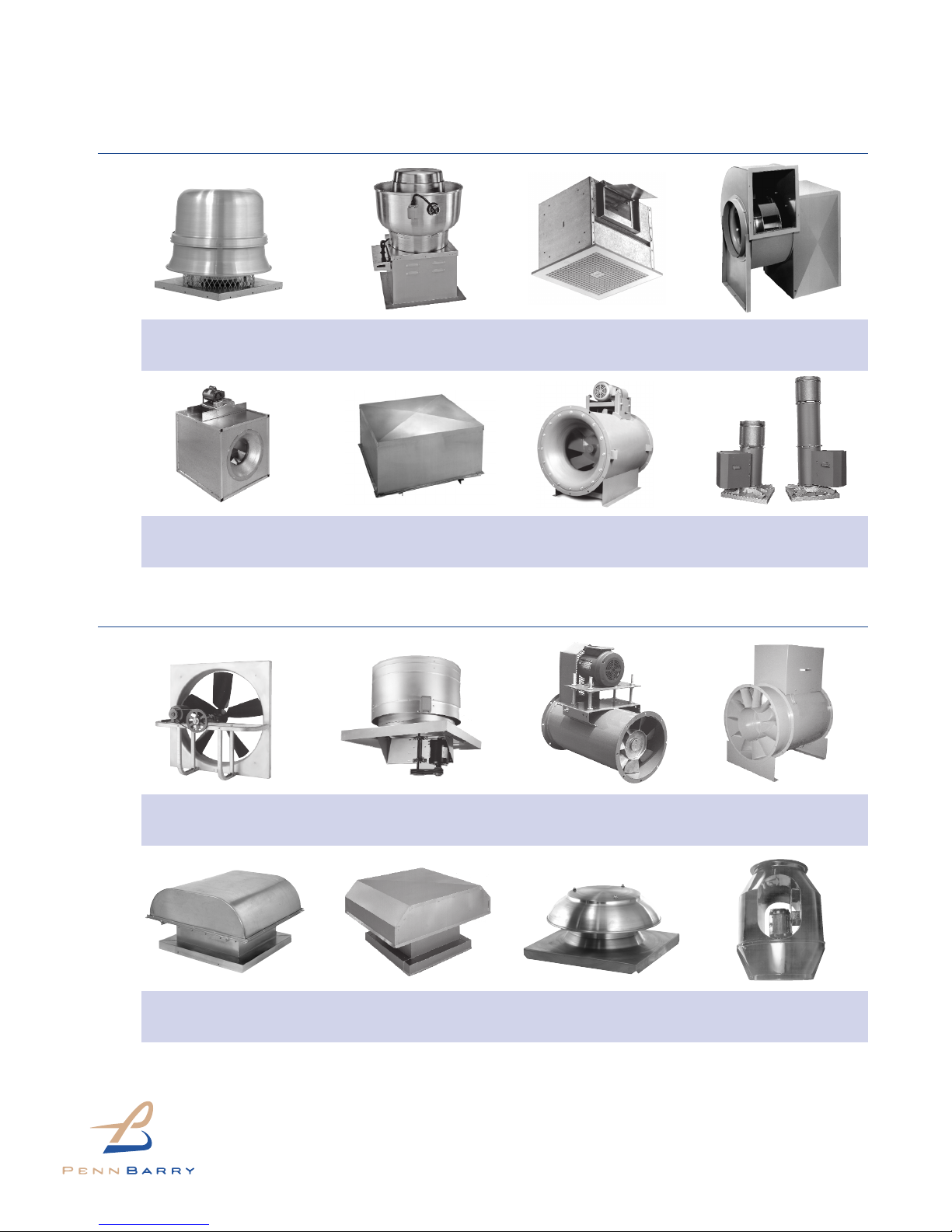
OTHER PENNBARRY PRODUCTS
CENTRIFUGAL PRODUCTS
Domex
Centrifugal
Roof Exhausters
Centrex Inliner
Centrifugal Inline Fans
Fumex Fatrap
Kitchen Hood Centrifugal
Roof Exhausters
LC Dynafan
Low Contour Centrifugal
Roof Exhausters
AXIAL / GRAVITY PRODUCTS
Zephyr
Ceiling and Inline Fans
ESI
Efficient Silent
Inline Fan
Dynamo
Centrifugal Blowers
Fume Exhaust
Curb Mounted
Centrifugal Fans
Breezeway
Propeller Wall Fans
Powered Airette
Axial Roof Ventilators
HI-EX
Power Roof Ventilator
Airette
Gravity Intake/Relief Hood
Tubeaxial
Inline Fans
Domex Axial
Axial Roof Ventilators
For more information contact your local PennBarry Sales
Manufacturer Representative or visit us at www.PennBarry.com
©2005 PennBarry™ All Rights Reserved. February 2005
Vaneaxial
Inline Fans
Axcentrix
Bifurcator Fan
 Loading...