

Page 1
1401 North Plano Road, Richardson, Texas 75081
Phone: 972-234-3202 Fax: 972-497-0468
Operation & Maintenance Manual
Breezeway Panel Fans: Direct & Belt Drive
Please read and save these instructions. Read carefully before attempting to assemble, install, operate or maintain the product
described. Protect yourself and others by observing all safety information. Failure to comply with instructions could result in personal
injury and/or property damage! Retain instructions for future reference.
Receiving and Handling
PennBarry fans are carefully inspected before leaving the factory. When the unit is received, inspect
for any signs of tampering. Inspect the unit for any
damage that may have occurred during transit and
check for loose, missing or damaged parts.
Mishandled units can void the warranty provisions.
If units are damaged in transit, it is the responsibility of the receiver to make all claims against the
carrier. PennBarry is not responsible for damages
incurred during shipment.
Avoid severe jarring and/or dropping. Handle units
with care to prevent damage to components or finishes. If the unit is scratched due to mishandling,
the protective coating may be damaged. Incorrect
lifting may damage the fan and void the warranty.
Storage
Long-term storage requires special attention.
Store units on a level, solid surface, preferably
indoors. If outside storage is necessary, protect the
units against moisture and dirt by encasing in plastic
or in some similar weatherproof material.
Periodically inspect units and rotate wheels to
spread bearing lubricant. Failure to rotate wheels
results in reduced bearing life and may void the
manufacturer’s warranty. If the unit will be stored for
an extended time, remove belts. Belts that remain
under tension in a stationary position for extended
periods are likely to have a reduced operating life.
Installation
Any accessories which have been provided
“knocked-down” can be assembled per illustrations provided (pages 6 - 9).
LOCATION AND GUARDS
All fans have moving parts which require
guarding in the same way as other moving machinery. Where the fan is accessible to untrained personnel or the general public, use maximum safety
guards, even at the cost of some performance.
Unprotected fans located less than 7' above the
floor require guarding as specified in the
Occupational Safety and Health Act (OSHA). UL
listed fans, to maintain their personal safety listing,
must be installed not less than 10 feet above the
floor. PennBarry recommends the use of guards on
all exposed non-ducted fans.
INSTALLING THE PANEL FAN
Wall openings must be square and must be minimum 1/2" greater than the outside dimension of the
panel fan housing, when recessed within the wall.
Level and securely anchor the fan to the wall
through holes pre-drilled in the mounting flange.
Use the type, size and number of fasteners suitable
to the unit size and wall construction. If the contractor removes ventilator parts, reassemble by placing
all spacers, washers, nuts, bolts, fasteners and
components exactly as they were prior to removal.
Tighten and secure all fasteners.
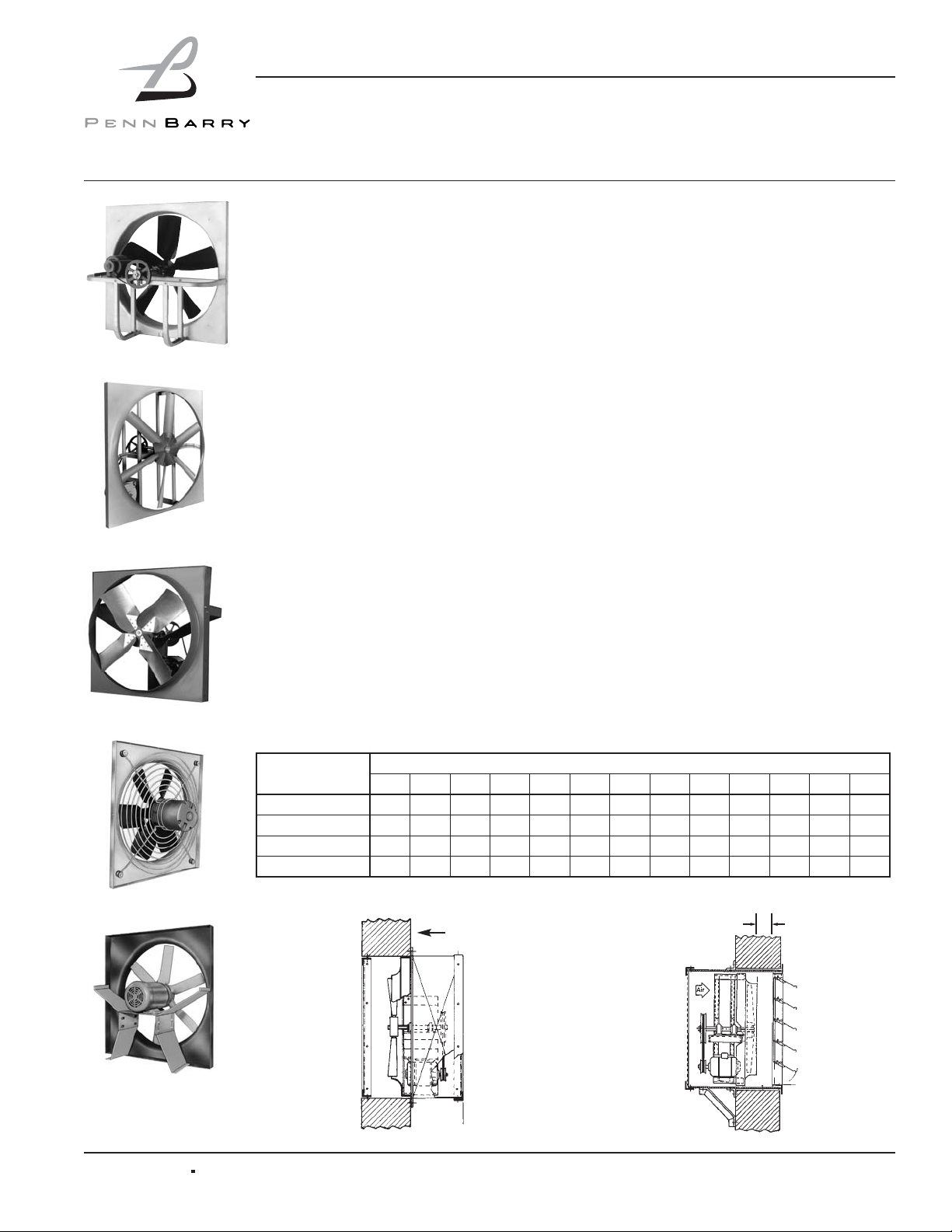
Type BHM/BHH
TYPE P
TYPE BCH
TYPE BLL
TYPE BC
Printed in the USA Jan 2005
PART#59277
Figure 1:
Rear Guard
Wall
Model
Dimension C (Inches)
10 12 14 16 18 20 24 30 36 42 48 54 60
P 4 4 - 4 4 5 5 - - - - - -
BX - 4 4 4 4 4 4 - - - - - -
BC/BLL/BCH - - - - - - 6 6 6 6 7 7.5 7.5
BHM/BHH - - - - - - 6 6 6 6 7 7 7
Figure 2:
Wall Sleeve
Minimum Clearance Between Fan and Shutter – Figure 2
C
Page 2
Operation & Maintenance Manual
Breezeway Panel Fans: Direct and Belt Drive
2 PENNBARRY
1401 North Plano Road, Richardson, Texas 75081
Phone: 972-234-3202 Fax: 972-497-0468
Follow all local electri-
cal, safety and building
codes, the provisions of the National
Electrical Code and the Occupational
Safety and Health Act.
POSITIONING AND RUNNING
POWER LINES
Power is normally brought from within the
building through proper conduit lines to
the wall opening, and in turn to the (disconnect switch, if furnished) motor.
When power lines are brought up to the
unit, provide a generous amount of slack
to allow for motor adjustments and to permit movement of motor for belt tension
adjustments. Ground motor adequately
and securely. Protect power lines from
sharp objects. Do not kink power line or
permit it to contact hot surfaces, chemicals, grease or oil. Use only UL recognized electrical parts, rated for proper
voltage, load and environment.
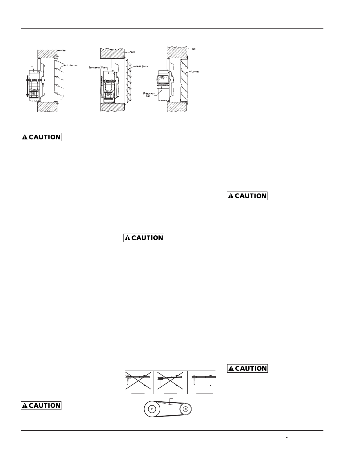
INSTALLING THE WALL SHUTTER
When required, level and fasten the wall
shutter through the mounting holes provided
in the shutter mounting flange. Consult
Figure 1 for the proper mounting arrangements. Secure the shutter to the wall opening without undue twisting which may distort
the frame. Check for free operation. If shutters are motor operated type, ascertain the
proper voltage is present on motor terminals.
The fan is now ready for service.
Start-Up and Operation
Carefully inspect the unit before start-up.
All motor bearings should be properly
lubricated and all fasteners should be
securely tightened. Rotate propeller by
hand to insure free movement.
Before placing hand on
impeller or belts, lock
out power source. Check all set-screws
and keys. Tighten when necessary.
BELT TENSION AND
PULLEY ALIGNMENT
Check condition of belts and the amount
of tension prior to start-up. DO NOT overtighten, as bearing damage will occur.
Recommended belt tension should permit
deflection of 1/64" per inch of span on
each side of belt measured halfway
between pulley centerline. Exercise
extreme care when adjusting belts so as
not to misalign the pulleys. Any misalignment will cause a sharp reduction in belt
life an produce squeaky , annoying noises.
On units equipped with two groove pulleys, adjust all belts with equal tension.
Whenever belts
are removed or
installed, never force belts over
pulleys without loosening motor first,
to relieve belt tension.
Make sure inlets and approaches to the
unit are free from obstruction. To assure
maximum air movement, make sure adequate supply air is available.
Before putting fan into operation, complete the following check list:
a. Turn off and LOCK OUT
power source.
b. Make sure installation is in
accordance with manufacturer’s
instructions.
c. Check and tighten all fasteners.
d. Spin propeller to see if
rotation is free.
e. Check all set-screws and keys:
tighten if necessary.
f. Torqued set screws have a colored
Torque Seal mark indicating the correct torque has been applied.
g. Check belt or direct drive coupling
for alignment (use recommended
belt tension gauges).
h. Check belt for proper
sheave selection.
i. Make sure there is no foreign or
loose material in ductwork leading to
and from fan or in the fan itself.
j. Properly secure all safety guards.
k. Secure all access doors to fan
and ductwork.
l. Check line voltage with
motor nameplate.
m. Check wiring.
(On single phase
motors, the terminal
block must be set up in accordance with
the nameplate instructions and/or wiring
diagram. This set up must match the line
voltage. If the motor is multi-speed or
multi-voltage, the winding leads must be
grouped and connected as shown on the
motor wiring diagram. The line voltage
must correspond with proper grouping of
motor leads. The wiring diagram must be
followed explicitly or serious motor or
starter damage will occur.)
The fan has been checked at the factory
prior to shipment for mechanical noises. If
mechanical noises should develop:
a. Check rotating components
for adequate clearance.
b. Check proper belt tension
and pulley alignment.
c. Check installation and anchoring.
d. Check fan bearings.
Switch on electrical supply and allow fan
to reach full speed. Check carefully for:
1. Correct rotation of the impeller.
Incorrect rotation
overloads motor
severely and results in serious motor
damage. To change rotation of three
phase units, interchange any 2 of the 3
line leads. On single phase units, change
the terminal block set-up following the
wiring diagram on the motor.
Figure 3: Typical Mounting Arrangements
Breezeway Fan
Wall Shutter
Recess Mounting
Louver
Wall Shutter
Surface Mounting
Figure 4: Pulley Alignment
WRONG WRONG CORRECT
Not to exceed 1/64” per inch of span
Page 3
2. Check motor and bearing temperatures for excessive heat against the
manufacturer’s recommendations.
Use care when touch-
ing the exterior of an
operating motor. Modern motors normally
run hot. They are designed to operate at
higher temperatures. This is a normal
condition but they may be hot enough to
be painful or injurious to the touch.
If any problem is indicated, TURN OFF
POWER TO UNIT IMMEDIATELY. Lock
out the electrical supply, check carefully
for the cause of the trouble and correct as
needed. Even if the fan appears to be
operating satisfactorily, shut down after a
brief period and check all fasteners, setscrews and keys for tightness.
During the first eight (8) hours of
operation, check the fan periodically
for excessive vibration or noise. At this
time, also check motor input current
and motor bearing temperatures to insure
that they do not exceed manufacturer’s
recommendations. After eight hours
of satisfactory operation, shut down
the fan and lock out the electrical power
to check the following items and adjust
if necessary:
a. All set-screws, keys and fasteners.
b. Drive coupling alignment.
c. Belt alignment.
d. Belt tension.
SUPPLY APPLICATIONS - FIELD
MODIFICATIONS (BHM/BHH ONLY)
To modify to the exhuast supply, propeller
must be “flipped” so that blade leading
edge is closest to the motor.
SPECIAL PURPOSE SYSTEMS
Explosive, corrosive, high temperatures,
etc., may require special construction,
inspection and maintenance. It is
necessary to observe the fan manufacturer’s recommendations and limitations
concerning the type of material to be
handled by the fan and its application
to special conditions.
Maintenance
Do not attempt maintenance on fan until
the electrical supply has been completely
disconnected. If a disconnect switch has
not been provided, remove all fuses from
the circuit and lock the fuse panel so they
cannot accidentally be replaced.
Lubrication is a primary maintenance
responsibility. Check all bearings periodically. Inspect belts for tightness. If the fan
is installed in a corrosive or dirty atmosphere, periodically clean the impeller, inlet
and other moving parts.
FAN SHAFT LUBRICATION
Fan shaft bearing pillow blocks are
factory greased eliminating the need for
greasing initially. Follow the lubricating
schedule recommended by the factory.
When required, apply grease while the
shaft is rotating. This practice should not
supersede any safety considerations.
Use low pressure
grease guns only. High
pressure guns tend to blow out
or unseat bearing seals, leaving the
bearing open to collect grime, dust
and foreign particles.
LUBRICATION SCHEDULE
a. Under average conditions where
ambient temperatures do not exceed
120°F, lubrication is required 1 to 2
times a year.
b. Under dirt laden atmospheres or
where there is a temperature range
of 120°F to 150°F, lubrication is
required from 3 to 6 times a year.
c. Under extreme temperature condi-
tions and extremely dirty atmospheres, lubrication should be at least
once or twice a month.
MOTOR LUBRICATION
In general, standard motors are furnished
with prelubricated, sealed-for-life ball
bearings which require no lubrication for
7 to 10 years of normal service. Where
motors have been ordered with greasable
bearings, these bearings are factory
lubricated and require no attention for one
year under normal conditions. If grease
relief fittings are provided, remove
them when performing maintenance
to allow grease to flow out. Whenever
possible, apply grease while the motor
is running. This practice should not
supersede any safety considerations.
DO NOT OVERGREASE, as most
lubricants deteriorate motor windings,
thereby reducing motor life.
Hidden Danger
In addition to the normal dangers of rotating machinery, fans present an additional
hazard in their ability to suck in not only
air, but loose material as well. Solid
objects can pass through the fan and be
discharged by the impeller as potentially
dangerous projectiles. Therefore, screen
intake to ductwork, whenever possible, to
prevent the accidental entrance of solid
objects. Never open access doors to a
duct system with the fan running.
When starting the fan for the first time,
completely inspect the ductwork and interior of the fan (with power locked off), to
make certain there is no foreign material
which can be sucked into or blown
through the ductwork.
Guards
All fans have moving parts which require
guarding in the same way as other
moving machinery.
Where the fan is accessible to untrained
personnel or the general public, use
maximum safety guards, even at the
cost of some performance loss.
Unprotected fans located less than
7' above the floor also require guarding
as specified in the Occupational Safety
and Health Act (OSHA).
PennBarry recommends the use of
guards on all exposed nonducted fans,
ceiling and wall mounted.
1401 North Plano Road, Richardson, Texas 75081
Phone: (972) 234-3202 Fax: (972) 497-0468
Operation & Maintenance Manual
Breezeway Panel Fans: Direct and Belt Drive
PENNBARRY 3
Manufacturer Product Temp. Range
BP LG-#P-1
Below 32°F
(0°C)
Gulf Gulfcrown EP-1
Imperial Oil Unirex EP-1
Shell Alvania R-1
BP
Energrease,
MPMK11
32°F to 150°F
(0°C to 66°C)
Gulf Gulfcrown EP-2
Imperial Oil Unirex EP-2
Shell Alvania R-3
Sun Oil Sun Prestige 42
Texaco Regal AFB2
Recommended Lubricants
Page 4

Operation & Maintenance Manual
Breezeway Panel Fans: Direct and Belt Drive
4 PENNBARRY
1401 North Plano Road, Richardson, Texas 75081
Phone: 972-234-3202 Fax: 972-497-0468
Troubleshooting Checklist
Note: Care should be taken to follow all local electrical, safety and building codes. Provisions of the National Electric Code (NEC), as wells as the Occupational Safety and Health Act (OSHA)
should be followed.
All motors are checked prior to shipment. If motor defects should develop, prompt service can be obtained from the nearest authorized service station of the motor manufacturer while under warranty. Exchange, repair or replacement will be provided on a no
charge basis if the motor is defective within the warranty period. The PennBarry representative in your area will provide a name and
address of an authorized service station if requested. WARNING: Motor guarantee is void unless overload protection is provided in
motor wiring circuit.
Symptom Possible Cause(s) Corrective Action
Excessive noise
1. Defective or loose motor bearings 1. Replace motor with same frame size, RPM, HP
2. Ventilator base not securely anchored 2. Reset properly
3. Loose or unbalanced wheel/propeller 3. Tighten screws, remove build-up,
balance wheel/propeller
4. Misaligned pulleys or shaft 4. correct alignment
5. Loose or damaged wheel/propeller 4. Replace wheel/propeller
6. Wheel running in wrong direction 6. Reverse direction
Fan inoperative
1. Blown fuse or open circuit breaker 1. Replace fuses or circuit breaker
2. Loose or disconnected wiring 2. Shut off power and check wiring
for proper connections
3. Defective motor 3. Repair or replace motor
4. Broken belts 4. Replace belts
Insufficient airflow
1. Clogged filters 1. Clean filters
2. Operation in wrong direction 2. Correct rotation of propeller
3. Insufficient make-up air direction 3. Add make-up fan or louver opening
Motor overheating
1. Belt slippage 1. Adjust tension or replace belts
2. Overvoltage or under voltage 2. Contact power supply company
3. Operation in wrong direction 3. Reverse direction of motor
4. Fan speed too high 4. Slow down fan by opening variable pitch
pulley on motor shaft
5. Incorrect motor (service factor 1.0,
low ambient temperature)
5. Replace motor with correct open,
NEMA service factors (1.15 or higher)
with 40 degrees ambient
6. Undersized motor 6. Check motor ratings with catalog speed
and air capacity chart
Page 5

Operation & Maintenance Manual
Parts Replacement
If replacing parts, do so with properly selected components which duplicate the original parts correctly.
Incorrectly sized shafts, belts, pulleys, impellers, etc.,
can damage the fan.
Typical Parts List
1. Panel
2. Venturi Orifice
3. Fan Blade (Cast Aluminum or Fabricated Steel)
4. Ball Bearing Motor
5. Structural Supports
6. Motor Mounting Plate
7. Fan Shaft and Bearings (Belt Drive Only)
8. Belt and Pulleys (Belt Drive Only)
Figure 5: Direct Drive Figure 6: Belt Drive
Breezeway Panel Fans: Direct and Belt Drive
PENNBARRY 5
1401 North Plano Road, Richardson, Texas 75081
Phone: 972-234-3202 Fax: 972-497-0468
Page 6

Operation & Maintenance Manual
Breezeway Panel Fans: Direct and Belt Drive
6 PENNBARRY
1401 North Plano Road, Richardson, Texas 75081
Phone: 972-234-3202 Fax: 972-497-0468
Wall Mounting Sleeve Assembly
NOTES:
1. Make sure all bends are to the outside.
2. Use caulk to seal all seams.
* 3. Varies by model side.
** 4. This hardware is used to attach the fan (not illustrated) into wall sleeve.
All bends
to the outside
Typical
conduit
access
Figure 7
Table 2: Parts List
Item Quantity Description
1 4 Wall Sleeve Panel
2 * 1/4-20 X 3/4 Self Tapping Screw
3** * 1/4-20 X 3/4 Whiz Bolt
4** * 1/4-20 Whiz Nut
Page 7

Operation & Maintenance Manual
Breezeway Panel Fans: Direct and Belt Drive
PENNBARRY 7
1401 North Plano Road, Richardson, Texas 75081
Phone: 972-234-3202 Fax: 972-497-0468
Weathershield Assembly
NOTES:
1. Make sure all bends are to the outside.
2. Use caulk to seal all seams.
* 3. Varies by model side.
All bends
to the outside
Figure 8
Table 3: Parts List
Item Quantity Description
1 1 Weather Cover Side (LEFT)
2 1 Weather Cover Side (RIGHT)
3 1 Weather Cover Top #1
4 1 Weather Cover Top #2
5 1 Weather Cover Bottom
6 * 1/4-20 X 3/4 Self Tapping Screw
Page 8

Operation & Maintenance Manual
Breezeway Panel Fans: Direct and Belt Drive
8 PENNBARRY
1401 North Plano Road, Richardson, Texas 75081
Phone: 972-234-3202 Fax: 972-497-0468
2 Piece Wall Mounting Sleeve/Weather Shield Guard
Assembly 54" & 60"
NOTES:
* 1. Equally space hardware connecting both halves of guard.
2. Guards 24 thru 48 are 1 piece with no assembly required.
Use item #1 to attach
to sheet metal
Figure 9
Table 4: Parts List
Item Quantity Description
1 40 1/4-20 X 3/4 Self Tapping Screw
2 2 Screen Guard
3* 5 3/8-16 X 1" Whiz Bolt
4* 5 3/8-16 Whiz Nut
5* 10 .390 X 1.875 Diameter Washer
Page 9

Operation & Maintenance Manual
Breezeway Panel Fans: Direct and Belt Drive
PENNBARRY 9
1401 North Plano Road, Richardson, Texas 75081
Phone: 972-234-3202 Fax: 972-497-0468
Rear/Front Guard Assembly
NOTES:
1. Assemble the sheet metal parts first then attach the screen second.
2. Make sure that all bends are to the outside.
3. Use caulk to seal all seams.
* 4. Varies by model size.
** 5. Guards 24 thru 48 are 1 piece with no assembly required. 54 & 60 are 2 pieces.
*** 6. Equally space hardware connecting both halves of guard (54 & 60).
All bends
to the outside
Figure 10
Table 5: Parts List
Item
Quantity
Description
Rear Front
1 4 4 Guard Panel
2 * * 1/4-20 X 3/4 Self Tapping Screw
3 ** ** Screen Guard
4*** 5 5 3/8-16 X 1" Whiz Bolt
5*** 5 5 3/8-16 Whiz Nut
6*** 10 10 .390 X 1.875 Diameter Washer
Page 10

Operation & Maintenance Manual
Breezeway Panel Fans: Direct and Belt Drive
10 PENNBARRY
1401 North Plano Road, Richardson, Texas 75081
Phone: 972-234-3202 Fax: 972-497-0468
Limited One Year Warranty
What Products Are Covered
PennBarry Fans and Ventilators (each, a "PennBarry Product")
One Year Limited Warranty For PennBarry Products
PennBarry warrants to the original commercial purchaser that the PennBarry Products will be free from defects in material and
workmanship for a period of one (1) year from the date of shipment.
Exclusive Remedy
PennBarry will, at its option, repair or replace (without removal or installation) the affected components of any defective PennBarry
Product; repair or replace (without removal or installation) the entire defective PennBarry Product; or refund
the invoice price of the PennBarry Product. In all cases, a reasonable time period must be allowed for warranty
repairs to be completed.
What You Must Do
In order to make a claim under these warranties:
1. You must be the original commercial purchaser of the PennBarry Product.
2. You must promptly notify us, within the warranty period, of any defect and provide us with any substantiation
that we may reasonably request.
3. The PennBarry Product must have been installed and maintained in accordance with good industry practice
and any specific PennBarry recommendations.
Exclusions
These warranties do not cover defects caused by:
1. Improper design or operation of the system into which the PennBarry Product is incorporated.
2. Improper installation.
3. Accident, abuse or misuse.
4. Unreasonable use (including any use for non-commercial purposes, failure to provide reasonable and necessary
maintenance as specified by PennBarry, misapplication and operation in excess of stated performance characteristics).
5. Components not manufactured by PennBarry.
Limitations
1. In all cases, PennBarry reserves the right to fully satisfy its obligations under the Limited Warranties by
refunding the invoice price of the defective PennBarry Product (or, if the PennBarry Product has been discontinued,
of the most nearly comparable current product).
2. PennBarry reserves the right to furnish a substitute or replacement component or product in the event a PennBarry
Product or any component of the product is discontinued or otherwise unavailable.
3. PennBarry's only obligation with respect to components not manufactured by PennBarry shall be to pass through
the warranty made by the manufacturer of the defective component.
General
The foregoing warranties are exclusive and in lieu of all other warranties except that of title, whether written, oral or
implied, in fact or in law (including any warranty of merchantability or fitness for a particular purpose).
PennBarry hereby disclaims any liability for special, punitive, indirect, incidental or consequential damages, including
without limitation lost profits or revenues, loss of use of equipment, cost of capital, cost of substitute products, facilities
or services, downtime, shutdown or slowdown costs.
The remedies of the original commercial purchaser set forth herein are exclusive and the liability of PennBarry
with respect to the PennBarry Products, whether in contract, tort, warranty, strict liability or other legal theory shall not exceed
the invoice price charged by PennBarry to its customer for the affected PennBarry Product at the time the claim is made.
Inquiries regarding these warranties should be sent to: PennBarry, 1401 North Plano Road, Richardson, TX 75081.
 Loading...