

Page 1
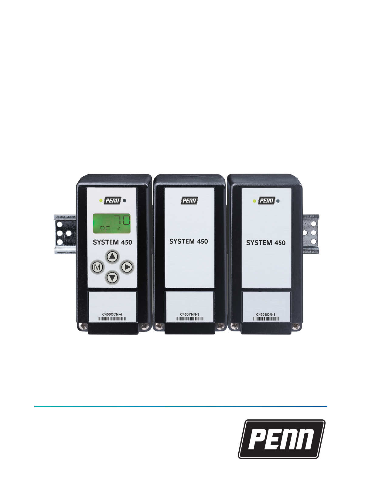
System 450 Series Modular Control
Systems with Standard Control Modules
Technical Bulletin
C450CBN, C450CCN, C450CPN, C450CQN, C450CPW, C450SPN, C450SQN, C450SBN, C450SCN, C450YNN
Johnson Controls LIT-12011459
www.penncontrols.com
2021-07-21
Page 2

2 System 450 Series Modular Control Systems with Standard Control Modules Technical Bulletin
Page 3

Contents
Contents
Introduction.................................................................................................................................................... 5
System 450 Overview..................................................................................................................................... 5
System 450 Control Systems with standard control modules....................................................... 6
Control module and UI....................................................................................................................... 7
Expansion modules, module assemblies, and outputs.................................................................. 9
Module assemblies, output types, and output numbers...................................................................... 9
Hybrid analog output........................................................................................................................ 10
System 450 compatible sensors and transducers......................................................................... 11
System 450 sensors and transducers for standard control modules................................................ 12
Binary input sensor.................................................................................................................................. 13
System 450 functional sensors............................................................................................................... 13
Relay outputs............................................................................................................................................ 14
Analog outputs......................................................................................................................................... 18
High input signal selection............................................................................................................... 24
Differential control............................................................................................................................ 24
Sensor Failure mode................................................................................................................................ 26
System 450 control system examples............................................................................................. 26
Control system example......................................................................................................................... 26
Hybrid analog and high input signal selection control system example.......................................... 31
Designing and building System 450 control systems.............................................................................. 33
Selecting, installing, and setting up sensors............................................................................................ 33
Assembling System 450 modules............................................................................................................... 34
Locating System 450 modules.................................................................................................................... 34
Mounting....................................................................................................................................................... 34
Mounting modules on DIN rail........................................................................................................ 34
Direct-mounting modules................................................................................................................ 35
Wiring System 450 components................................................................................................................. 35
Wiring System 450 sensors and transducers................................................................................. 39
Setting up a System 450 control system................................................................................................... 39
Determining output numbers and output types........................................................................... 39
System 450 UI navigation guidelines.............................................................................................. 40
Accessing and navigating the UI..................................................................................................... 40
Viewing the System Status screens....................................................................................................... 41
Accessing the System Setup screens..................................................................................................... 41
Setting up the sensors and transducers........................................................................................ 43
Setting up control system outputs............................................................................................................ 45
Relay output setup............................................................................................................................ 45
Setting up a relay output.................................................................................................................. 46
Analog output setup......................................................................................................................... 48
Setting up an analog output.................................................................................................................. 49
Pulse region hybrid analog output setup............................................................................................. 51
System 450 Series Modular Control Systems with Standard Control Modules Technical Bulletin 3
Page 4

Setting up a pulse region hybrid analog output.................................................................................. 51
Setting up outputs that reference a P 110 sensor............................................................................... 52
Determining the integration constant for an analog output................................................................. 53
Testing the slowest to fastest time integral to determine I-C setting........................................ 53
Using the response time to a step change to determine the I-C Setting................................... 54
Troubleshooting System 450 control systems.......................................................................................... 56
Specified voltage ranges for sensors.............................................................................................. 56
Repair and ordering information............................................................................................................... 57
Related documentation............................................................................................................................... 61
System 450 Series Modular Control Systems with Standard Control modules technical specifications
62
North American emissions compliance..................................................................................................... 67
United States...................................................................................................................................... 67
Canada................................................................................................................................................ 67
Glossary of terms......................................................................................................................................... 68
Product warranty......................................................................................................................................... 76
Single point of contact................................................................................................................................. 76
Contact information..................................................................................................................................... 76
System 450 Series Modular Control Systems with Standard Control Modules Technical Bulletin4
Page 5

Introduction
This document describes the System 450™ features and functions, and provides guidelines and
instructions to design, select, install, set up, and troubleshoot the System 450 controls that use
standard control modules (C450CBN-4, C450CCN-4, C450CPN-4, C450CQN-4) or the hybrid analog
output module (C450CPW-400).
This document also provides information and instructions to select, install, and set up sensors,
expansion modules, and the power module in your control systems with standard control modules
or the hybrid analog control module.
This document also provides System 450 Related Documentation and references to System 450
System 450 Overview.
For information about System 450 modules with reset control (C450RxN-x), refer to the System 450
Series Modular Control Systems with Reset Control Modules Technical Bulletin (LIT-12011842).
For information about System 450 modules with network communications, refer to the System 450
Series Modular Control Systems with Communications Control Modules Technical Bulletin (LIT-12011826).
Important: Use this System 450 Series Modular Control Systems with Standard Control
Modules only as an operating control. Where failure or malfunction of the System 450 Control
System could lead to personal injury or property damage to the controlled equipment or
other property, additional precautions must be designed into the control system. Incorporate
and maintain other devices, such as supervisory or alarm systems or safety or limit controls,
intended to warn of or protect against failure or malfunction of the System 450 Control
System.
Important: Utiliser ce System 450 Series Modular Control Systems with Standard Control
Modules uniquement en tant que dispositif de contrôle de fonctionnement. Lorsqu'une
défaillance ou un dysfonctionnement du System 450 Control System risque de provoquer des
blessures ou d'endommager l'équipement contrôlé ou un autre équipement, la conception
du système de contrôle doit intégrer des dispositifs de protection supplémentaires. Veiller
dans ce cas à intégrer de façon permanente d'autres dispositifs, tels que des systèmes de
supervision ou d'alarme, ou des dispositifs de sécurité ou de limitation, ayant une fonction
d'avertissement ou de protection en cas de défaillance ou de dysfonctionnement du [nom
abrégé de l'appareil].
System 450 Overview
The System 450 Series is a family of compact digital electronic control, expansion, and power
modules that you can assemble and set up to provide on/off and proportional control of
temperature, pressure, and humidity conditions in a wide variety of HVAC, commercial, or industrial
process applications.
The System 450 Series replaces the System 350 Series and System 27 Series control systems, and
provides more features and flexibility with fewer model variations. Most System 350 and System 27
modules are designed for single condition applications, such as temperature, pressure, or humidity;
you cannot configure them to control multiple conditions with a single control system. Based on the
control module model you have, a single System 450 control system can monitor and control both
temperature and humidity, or temperature, pressure, and humidity simultaneously.
Note: System 450 modules are not compatible with System 350 or System 27 modules.
However, you can build all of the System 350 and System 27 control systems and many more
with fewer System 450 modules.
The System 450 Series has several model variations. Each module is designed to be multi-purpose,
adaptable, and completely field configurable for temperature, pressure, and humidity applications.
Use the System 450 Series to build a wide range of inexpensive, compact, durable, and versatile
5System 450 Series Modular Control Systems with Standard Control Modules Technical Bulletin
Page 6

custom control systems to monitor and control multiple control loops in your controlled system. A
System 450 control system can monitor temperature, pressure, and humidity simultaneously and
control up to 10 analog, relay, or both outputs based on the monitored conditions.
Note: System 450 communications control modules, System 450 standard control modules,
and the System 450 control module with hybrid analog output can monitor and control
temperature, pressure, and humidity applications simultaneously. System 450 reset control
modules can monitor and control temperature and humidity applications simultaneously.
A System 450 standard control system includes the following features:
• A single System 450 standard control module that provides the control system UI to set up,
monitor, and control your system and the sensor wiring terminals for connecting the sensors
to your control system
• One to 10 outputs provided by the control module and expansion modules. Each output
provides either on/off control or a proportional analog signal of 0 VDC to 10 VDC or 4 mA to 20
mA to the equipment in your controlled system
• One to three sensors or transducers that you can hard-wire directly to the control module and
can provide input signals to monitor and control your system equipment
• An optional power module to provide power to the connected control module and expansion
modules
See Table 12 for a list of System 450 modules that can be used in standard and hybrid analog
output control systems. Refer to the System 450 Series Modular Controls Product Bulletin
(LIT-12011458) for a complete list and description of the System 450 modules, compatible sensors
and transducers, and accessories.
System 450 Control Systems with standard control modules
A System 450 Control system with a standard control module can provide the following types of
control to your application:
• On/off control: includes multi-stage control for temperature, pressure, and humidity
applications. See Relay Outputs.
• Proportional analog control: includes multi-stage control for temperature, pressure, and
humidity applications. See Analog Outputs.
• Combination of on/off relay and analog output control: includes up to 10 outputs for each
control system and any combination of relay and analog outputs.
• Multi-stage control for relay or analog: for temperature, pressure, and humidity
applications.
• Multi-purpose control: includes simultaneous monitoring and control of temperature,
pressure, and humidity conditions.
• Stand-alone control: a single standard control module that you can configure to replace a
wide variety of specialized controls in the field.
• Binary input control: connect a set of binary contacts or dry contacts to any System 450 input
and control your system’s relay outputs. See Binary Input Control for Relay Outputs.
• Direct and reverse action proportional control. See Direct and Reverse Control Actions for
Analog Outputs.
• Proportional plus integral control. See Proportional Plus Integral Control and Integration
Constants.
System 450 Series Modular Control Systems with Standard Control Modules Technical Bulletin6
Page 7
• High input signal selection: monitor a condition with two or three identical sensors at
different locations in your controlled system and control system outputs according to the
highest condition value monitored by the sensors. See High Input Signal Selection.
• Differential control: monitor and control a condition differential in a controlled system; for
example, the water pressure drop across an in-line water filter. See Differential Control.
• Hybrid analog output control: C450CPW-400 enables an analog VDC output to transition to
a pulse output at low signal levels to provide more efficient low-speed control of electronically
commutated (EC) motors in condenser fan applications. See Hybrid Analog Output.
• Output update rate: select the rate at which an analog output updates the output signal to
the controlled equipment. See Analog Output Update Rate.
• Output signal deadband : create a deadband for the analog output signal within which the
output signal strength remains constant. See Analog Output Deadband.
• Four time control parameters : set up the relay outputs with On or Off time delays and
minimum On or Off times. See Relay On and Off Duration Control.
• On/off delay: configure an on delay for the time between a setpoint trip and the energizing of
a relay, and an off delay for the time between a setpoint trip and the de-energizing of a relay.
Note: The C450CPW-400 model only provides a hybrid analog output for direct control of EC
motors. See Hybrid Analog Output.
Control module and UI
Each System 450 standard control system requires a single control module. System 450 Control
modules have an LCD that you can use to set up and monitor your control system, along with a
four-button touchpad to navigate the control system status and setup screens, and set up the
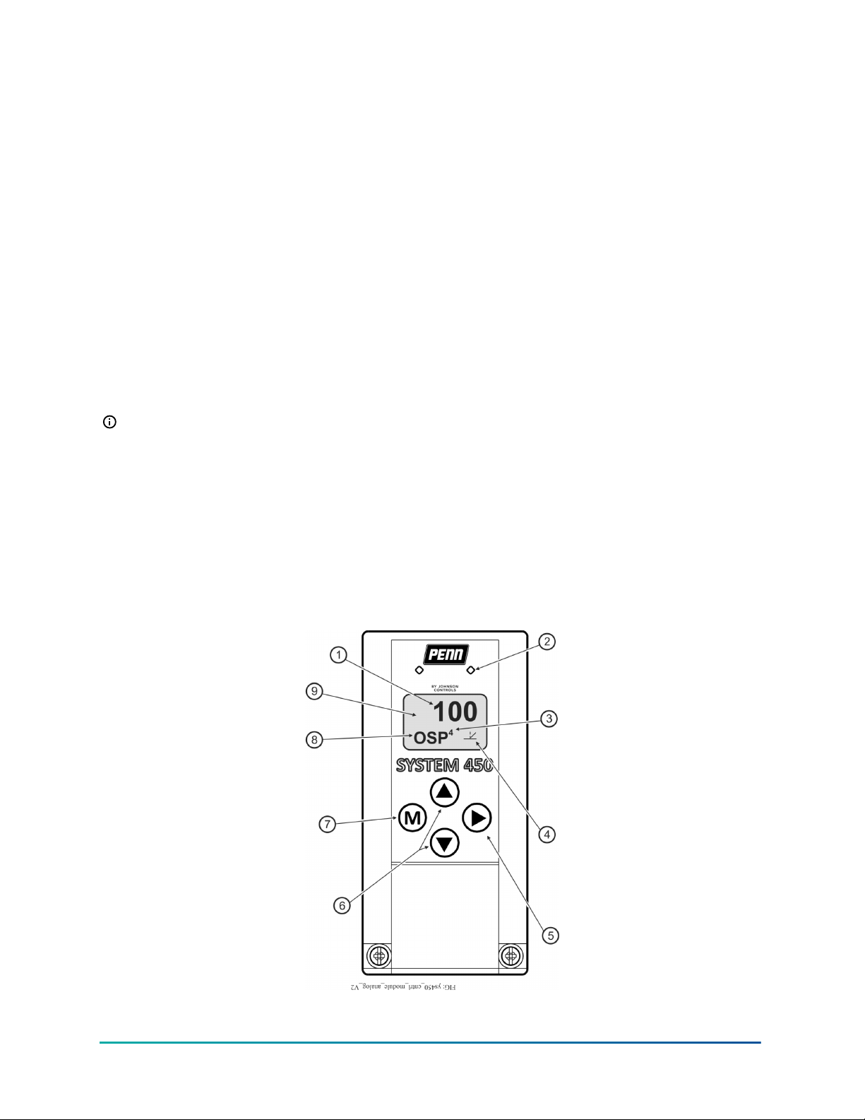
system parameters. Figure 1 shows a control module and Table 1 describes the features of the
System 450 control system UI for control modules.
Figure 1: System 450 control module output analog LEDs, LCD, four-button touchpad UI
7System 450 Series Modular Control Systems with Standard Control Modules Technical Bulletin
Page 8
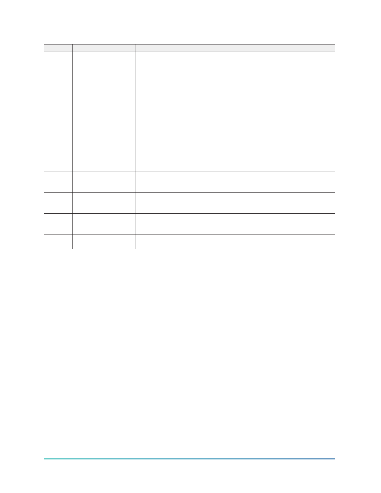
Table 1: System 450 control module output analog LEDs, LCD, four-button touchpad UI
Callout Feature Description
1 Status or setup value Displays the current input status, output status, or setup parameter value for
the displayed input for the Main screens. Press Up or Down to select a different
parameter value when the value flashes. Here, 100 = 100%.
2 LED Green LEDs on the control module and expansion modules indicate if the associated
relay or analog output is on or off. If the analog output is partially on between 0 V–10
V, the LED blinks. The higher the output signal strength, the longer the LED is on.
3 Output number Displays a numerical value that identifies the output associated with the status or
setup value shown on the screen. Output numbers are automatically determined
by the outputs' physical positions of left to right in the module assembly. Here, 4 =
Output 4.
4 Control Ramp icon Displays whether an analog output is set as direct-acting or reverse-acting, and
whether the output signal strength is at minimum or maximum when the sensed
property is at setpoint. The control ramp icon displayed is determined by the
output's SP, EP, OSP, and OEP setup values.
5 Next button In the Main screens, press Next to scroll through the system status screens. In a
setup screen, press Next to save the flashing setup value and go to the next setup
screen.
6 Up and Down buttons Press Up or Down to select a different value for any flashing value in the setup value
field. In the Main sensor status screens, press and hold both Up and Down for 5
seconds to access the setup Start screens.
7 Menu button Press M to move through the sensor and output setup start screens. When you
move through the status or setup screens, press M to return to the status start
screen or setup start screen.
8 Status or setup identifier Displays the unit of measurement, output, sensor number, or setup parameter for
the displayed status or setup value. Here, the setup identifier OSP represents %
output signal strength at setpoint.
9 LCD Backlit LCD screen. The LCD brightness is adjustable. During normal operation, the
LCD displays the main screens.
Standard System 450 control modules are available with one or two relay outputs or with one or
two analog outputs and the standard System 450 firmware. See Table 12 for model descriptions and
System 450 Control Systems with Standard Control Modules for more information.
The System 450 control module with hybrid analog output has a single analog output that can be
configured as a hybrid analog output to optimize and extend the controlled speed range of variable
speed EC motors. See Hybrid Analog Output for more information.
All System 450 control modules can control both relay outputs and analog outputs, regardless of
the type of outputs that the control module has on-board. You set up all of the sensors and all of
the relay and analog outputs, including the expansion module outputs, in the control module UI.
You can also configure a standard control module as a simple stand-alone control system when
your application requires only one or two relay outputs, or one or two analog outputs.
During normal operation, the LCD displays the Main System 450 sensor status screens, which
automatically scroll through and display the status of the hard-wire and functional sensors in your
control system. You can also view the status of all the outputs in your control system and access
the System Setup screens from the Main screens in the System 450 UI. See Setting up a System 450
Control System.
The System 450 System Status screens display the status of each output in the control system in
addition to the sensor status screens. A relay output status displays as On or OFF. An analog output
status displays as a percentage of the total output signal strength, 0% to 100%. The analog output
status screens also display an icon that indicates the control action of the analog output. See Direct
and Reverse Control Actions for Analog Outputs.
Figure 3 illustrates the System 450 UI navigation paths, parameter designations, and values for
the control system example, shown in Figure 2, using a System 450 standard control module.
System 450 Series Modular Control Systems with Standard Control Modules Technical Bulletin8
Page 9
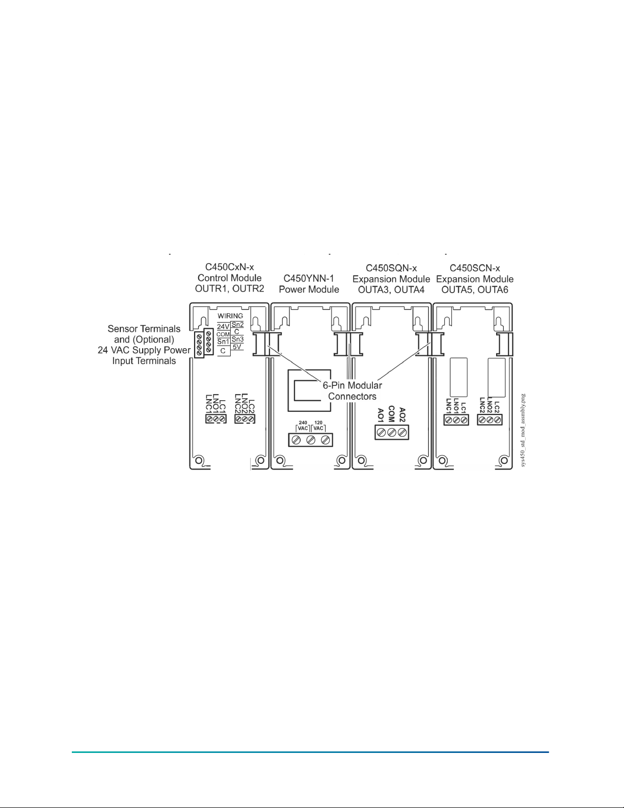
Figure 3 shows the Main screens, the Sensor Status screens, the System Status screens, the System
Setup screens, and the Output Setup screens for examples of the System 450 standard control
application.
Expansion modules, module assemblies, and outputs
System 450 expansion modules provide additional outputs to expand your control systems and
meet your specific application requirements.
A System 450 control system provides up to 10 outputs, and can consist of any combination of relay
and analog outputs. Expansion modules are available with one or two relay outputs, or with one or
two analog outputs. See Table 12 for information about the System 450 modules that you can use in
a control system.
Figure 2: System 450 module assembly example showing standard control module and
expansion module positions, output positions, and output numbers
Module assemblies, output types, and output numbers
You can plug System 450 modules together using the 6-pin connectors located on the sides of the
modules’ housings and mount these module assemblies on a recommended standard 35 mm DIN
rail or directly to a hard, even surface. See Mounting.
Figure 2 shows a System 450 module assembly example, the module positions, the output types,
and the automatically assigned output numbers that the System Setup screens in the control
module UI use.
The control module is always mounted on the left side of the module assembly. If a System 450
power module is used, the power module is always plugged into the right side of the control
module. If expansion modules are used, you can plug them into the assembly in any order on the
right side of the power module, or on the right side the control module, if a power module is not
used in the assembly. See Assembling System 450 Modules.
Each time a System 450 module assembly is powered on, the control module polls all of the
modules to identify if the output type is relay or analog, and assigns an output number from 1 to
9 and 0 = 10 to each output, starting with the first output of the control module, and then polling
each expansion module connected to the right. Output numbers display on the control module
LCD to identify the output that you view as you navigate the system status and setup screens in the
System 450 UI (Figure 3).
9System 450 Series Modular Control Systems with Standard Control Modules Technical Bulletin
Page 10
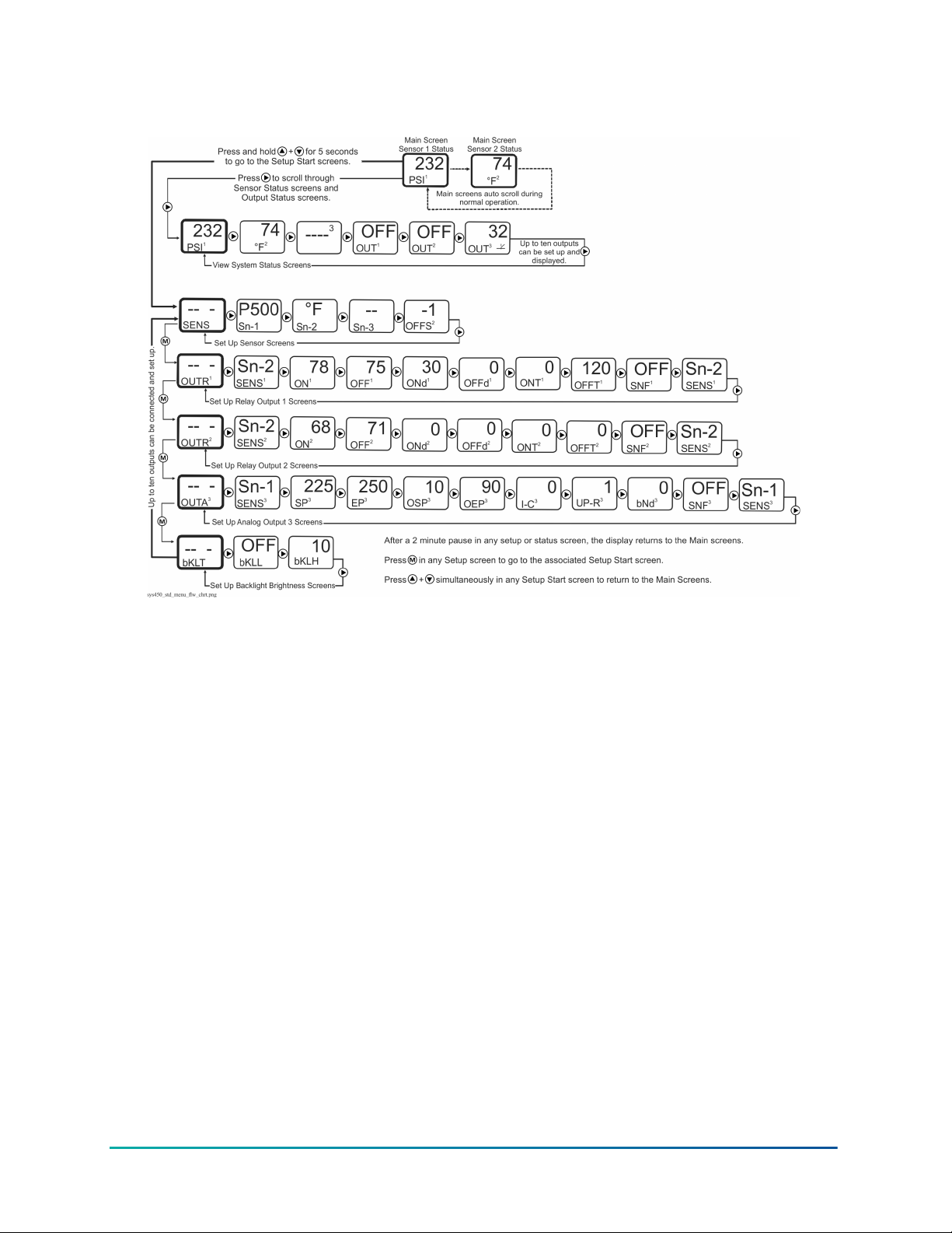
Figure 3: System 450 control module UI menu flow chart example showing navigation paths
and example settings in the Main, System Status, Sensor Setup, and Output Setup screens
Hybrid analog output
You can use the C450CPW-400 control module with variable speed EC fan motors on a wide variety
of refrigeration and HVAC condensing units.
The C450CPW-400 module has a single onboard analog output that you can configure as a hybrid
analog output to optimize and extend the controlled speed range of variable speed EC motors. You
can also set up the onboard analog output for High Input Signal Selection to enable precise and
efficient EC motor speed control on multi-circuit condensing units.
Hybrid analog output control enables the C450CPW-400 control module’s hybrid analog output
to transition between a pulse output and a standard VDC output, depending on the sensor value
relative to the proportional band. At low output levels, the pulse output signal provides an average
motor speed that is less than the EC motor’s fixed minimum speed (Figure 4).
System 450 Series Modular Control Systems with Standard Control Modules Technical Bulletin10
Page 11
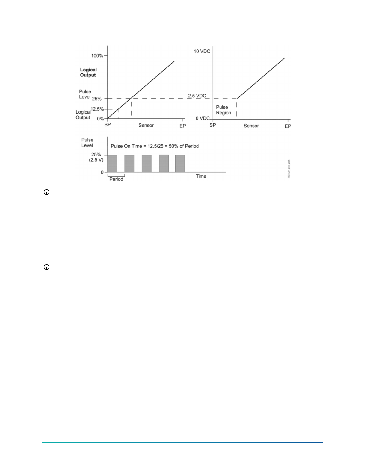
Figure 4: Pulse signal with pulse level = 25% and logical output = 12.5%
Note: You can configure Analog Output 1 (OUTA1) only on the C450CPW-400 control module
as a hybrid analog output and use the High Input Signal Selection feature. These features are
not available for any of the other outputs in control systems that use a C450CPW-400 control
module.
System 450 compatible sensors and transducers
System 450 standard control modules can operate with a variety of compatible sensors and
transducers. The System 450 compatible sensors and transducers cover a wide range of
temperature, pressure, and humidity conditions.
Note: System 450 compatible sensors consist of temperature sensors, humidity sensors,
and pressure transducers. The term sensor refers to all System 450 compatible input devices
including transducers, unless noted otherwise.
System 450 compatible sensors also come in a variety of styles and configurations; you can select
the sensor or transducer that best fits your control system requirements. See Table 14 through
Table 23 in Repair and ordering information for more information about System 450 compatible
sensors for communications control modules.
You can connect up to three sensors to a System 450 control module at the low-voltage terminal
block. See Wiring System 450 Components for more information on System 450 sensor wiring
terminals on control modules. Refer to the System 450 module installation instructions and the
sensor installation instructions referenced in System 450 Overview for information about how to
install, wire, operate, troubleshoot, and replace System 450 compatible sensors.
For each sensor in your control system, select the sensor’s corresponding Sensor Type when you
set up the sensors in the System 450 UI. A sensor’s corresponding Sensor Type determines the
controlled condition, unit of measurement, minimum differential, setup values, and ranges for each
output that is set up to reference the sensor.
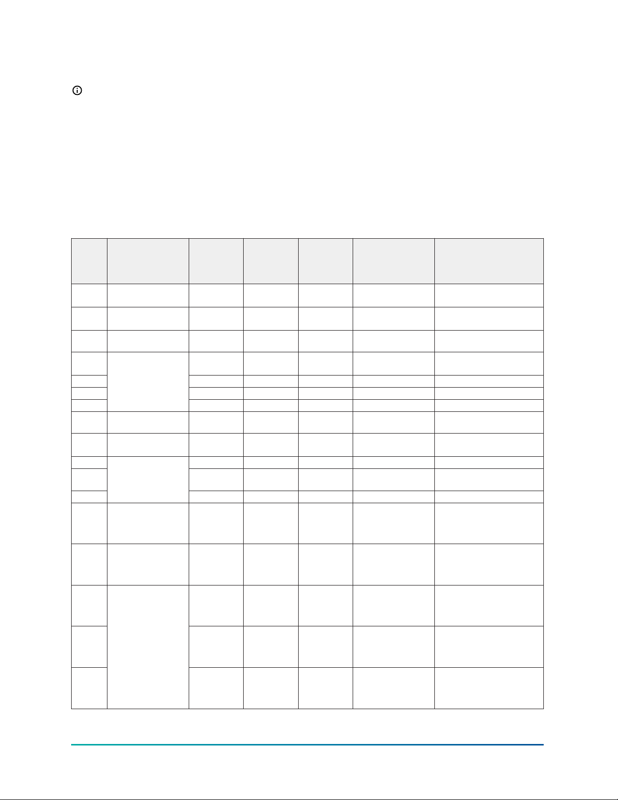
See Table 2 for information about Sensor Types, the corresponding output setup values and ranges,
sensor models, and transducer models used in standard System 450 control systems.
The System 450 control automatically designates the sensor connected to the Sn1 terminal and
a common (C) terminal as the Sn-1 sensor in the UI. The sensor connected to the Sn2 and a C
11System 450 Series Modular Control Systems with Standard Control Modules Technical Bulletin
Page 12
terminal is designated Sn-2, and the sensor connected to Sn3 and a C terminal is designated Sn-3.
You set up each sensor in the corresponding sensor setup screens in the UI.
Note: For a System 450 control system to operate properly, you must wire the correct sensor
or transducer model to the correct sensor input terminals on the control module and select
the correct Sensor Type in the corresponding Select Sensor Type screen in the System 450 UI.
See Setting up a System 450 Control System and Setting Up the Sensors and Transducers for more
information and procedures about how to set up sensors and Sensor Types in the System 450 UI.
System 450 sensors and transducers for standard control modules
The following table shows the Sensor Types, output setup values, value ranges, and product types
for the temperature sensors, humidity sensors, and pressure transducers that are compatible with
System 450 standard control modules.
Table 2: System 450 sensor types, setup values, and senso and transducer product codes
Sensor
type
°F °F; temperature or
°C °C; temperature or
rH %; humidity or %RH 1 to 100 10 to 95 1 2 HE-68Nx-0N00WS
P 0.25 -0.250 to
P 0.5 0 to 0.5 0.025 to 0.5 0.005 0.010 DPT2650-0R5D-AB
P 2.5 0 to 2.5 0.1 to 2.5 0.02 0.1 DPT2650-2R5D-AB
P 5
P 8 bAR; pressure or bar -1 to 8 -1 to 8 0.05 0.1 P599RCHS401C
P 10 INWC; pressure or
P 15 -1 to 15 -1 to 15 0.1 0.2 P599RCPS402C
P 30 0 to 30 0 to 30 0.1 0.4 P599RCHS404C
P 50
P 100 PSI; pressure or psi 0 to 100 0 to 100 0.5 1 P599RAPS101C
P 110 Hg/PSI; pressure or
P 200 0 to 200 0 to 200 1 1 P599RAPS102C
P 500 0 to 500 90 to 500 1 5 P599RAPS105C
P 750
Unit of
measurement
value; condition or
units
degrees
degrees
INWC; pressure or
in. W.C.
in. W.C.
bAR; pressure or bar
Hg-psi
PSI; pressure or psi
Effective
sensing
range
-46 to 255 -40 to 250 1 1 A99x-xxx
-43 to 124 -40 to 121 0.5 0.5 A99x-xxx
0.250
0 to 5.0 0.25 to 5.0 0.05 0.25 DPT2650-005D-AB
0 to 10 0.5 to 10 0.05 0.2 DPT2650-10D-AB
0 to 50 0 to 50 0.2 0.4 P599RCPS405C
-10 to 100 -10 to 100 0.5 1 P599RAPS100C
0 to 750 150 to 750 2 6 P599RAPS107C
Range of
usable
values
-0.225 to
0.250
Resolution
increment
value
0.005 0.010 DPT2650-R25B-AB
Minimum
proportional or
control band
Sensor product type
number
HE-69Sx0NP
P599RCPS401C
P599RCPS404C
P599RAPS101K
P599RCPS101C
P599RCPS101K
P599RAPS100K
P599RCPS100C
P599RCPS100K
P599RAPS102K
P599RCPS102C
P599RCPS102K
P599RAPS105K
P599RCPS105C
P599RCPS105K
P599RAPS107K
P599RCPS107C
P599RCPS107K
System 450 Series Modular Control Systems with Standard Control Modules Technical Bulletin12
Page 13
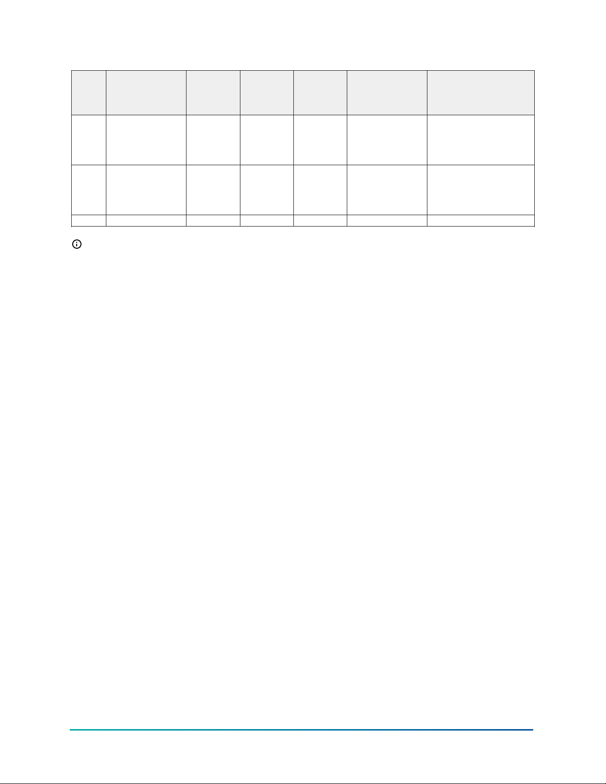
Table 2: System 450 sensor types, setup values, and senso and transducer product codes
Sensor
type
HI°F °F; temperature or
HI°C °C; temperature or
bin Open or Closed N/A N/A N/A N/A N/A
Unit of
measurement
value; condition or
units
degrees
degrees
Effective
sensing
range
-50 to 360 -40 to 350 1 1 TE-631x
-45.5 to 182 -40 to 176 0.5 0.5 TE-631x-x
Range of
usable
values
Resolution
increment
value
Minimum
proportional or
control band
Sensor product type
number
TE-6000-1
TE-6000-1x
TE-6000-6
TE-68NT-0N00S
TE-6000-1
TE-6000-1x
TE-6000-6
TE-68NT-0N00S
Note:
• The System 450 Differential Sensor Sn-d is set up and calculated with the two identical
sensors Sn-1 and Sn-2. This set up means that the range of usable values is twice as large
as a single sensor. See Differential control for the range of usable values when an output
references Sn-d.
• See Repair and ordering information for more information about the compatible sensors
for the System 450.
• See Setting up control system outputs for information about how to set up System 450
outputs that reference the P110 Sensor Type.
• Many of the temperature sensors that you can set up as HI°F or HI°C Sensor Types are not
designed for use across the entire range of usable values for HI°C HI°F and Sensor Types.
See Repair and ordering information or System 450 Series Modular Control Systems with
Standard Control modules technical specifications to determine the sensor hardware
configuration and temperature. The TE-6000-6 Nickel Sensor is the only sensor that you
can use over the entire temperature range.
• If you select the bin Sensor Type for a Sn-1, Sn-2, or Sn-3 sensor, the input sets up to
control the relay outputs only, based on the state of the binary input contacts, open or
closed, connected to the Sn1, Sn2, or Sn3 sensor input . See Binary input control for relay
outputs.
Binary input sensor
You can connect a binary input with dry contacts to any of the three System 450 control module
Sn1, Sn2, or Sn3 inputs and control output relays in your control system based on the binary input
state of open or closed.
A Sn1, Sn2, or Sn3 input set up as a binary input can be referenced by relay outputs only. Sensors
set up as binary inputs are not available for selection when you set up an analog output. When you
select a sensor in the UI that is set up as a binary input, the On value and the OFF value selection
screens are not available in the Relay Output Setup screens. See Binary Input Control for Relay
Outputs.
System 450 functional sensors
System 450 control modules also enable several functional sensors based on the input from one or
more of the hard-wired sensors in your control system. Selecting a functional sensor for an output
13System 450 Series Modular Control Systems with Standard Control Modules Technical Bulletin
Page 14

on a System 450 control system enables the differential or high signal selection control features on
the output.
System 450 standard control modules provide for three functional sensors:
• When Sn-1 and Sn-2 are set up as the same Sensor Type, the High Input Signal Selection
functional sensor (HI-2) and Differential Control functional sensor (Sn-d) are enabled and
available in the Sensor Selection screens for each output in the control system.
• When Sn-1, Sn-2, and Sn-3 are the same Sensor Type, the High Input Signal Selection functional
sensor (HI-3) is also enabled and available.
See High Input Signal Selection and Differential Control for more information about these
functional sensors and system control features.
Relay outputs
Relay outputs provide low and line-voltage on/off control for devices and equipment in your
controlled systems. Each relay output is a single-pole, double-throw (SPDT) set of dry contacts. See
Figure 18.
Note: System 450 output relays are SPDT dry contact relays only and they do not provide any
power source for your controlled equipment.
Selecting an ON value that is less than the OFF value (ON < OFF) turns the relay on when the sensed
condition value decreases, which is the typical heating mode in temperature applications and
referred to as reverse-acting on/off control.
Selecting an ON value that is greater than the OFF value (ON > OFF) turns the relay on when the
sensed condition value increases, which is the typical cooling mode in temperature applications and
referred to as direct-acting on/off control.
You can set up multiple relay outputs to create a variety of equipment staging control systems.
See Wiring System 450 Components for information on wiring output relays. See Related
Documentation for the relay output electrical ratings.
A green LED on the relay control and relay expansion module housings (Figure 1) indicates the
relay output status.
When a relay output is On:
• the corresponding green LED on the module housing is lit
• the LC to line normally open (LNO) relay contact is closed
• the LC to line normally losed (LNC) relay contact is open
• the corresponding Output Status screen in the UI displays On
When a relay output is Off:
• the corresponding green LED on the module housing is not lit
• the LC to LNO relay contact is open
• the LC to LNC relay contact is closed
• the corresponding Output Status screen in the UI displays OFF
System 450 control and expansion modules are available with one or two relay outputs. See Table
12 and Related Documentation for more information about the System 450 series modules.
A relay output’s control action is determined by the values that you select in the ON and OFF relay
output setup screens:
• Relay ON values (ON) are the values at which the relay turns On.
System 450 Series Modular Control Systems with Standard Control Modules Technical Bulletin14
Page 15
• Relay Off values (OFF) are the values at which the relay turns Off.
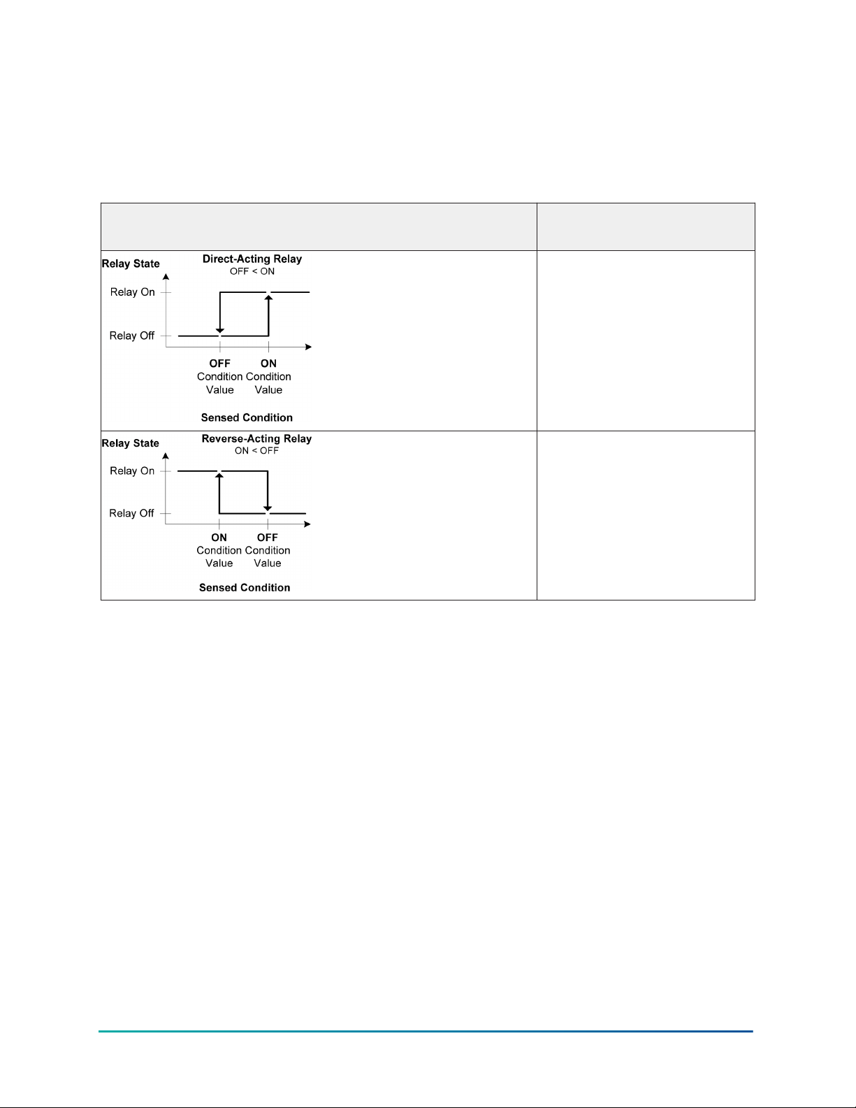
Table 3 illustrates direct and reverse relay actions. When you select On/Off condition values where
OFF is less than On, the output relay is a direct-acting relay. When you select condition values
where On is less than Off, the output relay is a reverse-acting relay.
Table 3: System 450 output relay control actions and the relationship between ON and OFF
values
Control action Set the relay output ON/OFF value
relationships for the preferred control
action
OFF < ON
ON < OFF
In temperature applications, direct-acting relays are often used to control cooling equipment, while
reverse-acting relays are often used to control heating equipment.
In pressure applications, direct-acting relays are often used for condenser fan cycling control or
pump-down control, while reverse-acting relays may be used for high pressure cut-out.
In humidity applications, direct-acting relays often control dehumidification equipment, and
reverse-acting relays often control humidification equipment.
Binary input control for relay outputs
You can connect a binary input or a set of dry contacts to any of the three Sn-1, Sn-2, orSn-3 and
C control module inputs and control the output relays in your control system based on the binary
input’s state of open or closed.
A Sn-1, Sn-2, or Sn-3 sensor set up as a binary input can only be referenced by a relay output.
Sensors set up as binary inputs are not available for selection when you set up an analog output.
When a relay output references a Sn-1, Sn-2, or Sn-3 sensor that is set up as a binary input, the
ON and OFF parameter screens are not available as you set up the output. The relay output’s On/
Off state is controlled by the binary input’s state and any of the ONT, OFFT, ONd, or OFFd timer
parameters that you set up for the relay output. When the binary input is closed, the relay is On.
When the binary input is open, the relay is Off. If no timer parameters are used, the relay output
state directly follows the binary input state. Figure 5 and Figure 6 show examples of the binary
input state and the resulting output states with and without the timer parameters applied to the
output.
15System 450 Series Modular Control Systems with Standard Control Modules Technical Bulletin
Page 16

See Relay On and Off Duration Control for more information about binary input control, relay
output behavior, and the resulting On/Off behaviors when applying the On/Off Delay Time and the
Minimum On/Off Time parameters.
Relay on and off duration control
The System 450 provides four time duration control parameters that can be applied to the relay
output On or Off times generated by an input sensor or a binary input. Each of the four On or Off
duration control parameters can be set up for 0 to 300 seconds (5 minutes) in 1-second intervals.
The four time duration control parameters are as follows:
• On delay: (ONd) Delays the time that a relay output goes to the On state after reaching the On
condition. See the third graph in Figure 5.
• Off delay: (OFFd) Delays the time that a relay output goes to the Off state after reaching the
Off condition. See the bottom graph in Figure 5.
• Minimum on time: (ONT) Maintains the relay in the On state for the selected minimum time
after reaching the On condition and overrides any sensor input that would normally switch the
relay off during the Minimum On Time interval. See the third graph in Figure 6.
• Minimum off time: (OFFT) Maintains the relay in the Off state for the selected minimum time
after reaching the Off condition and overrides any sensor input that would normally switch the
relay on during the Minimum Off Time interval. See the bottom graph in Figure 6.
The top two graphs in Figure 5 and Figure 6 show an example of a binary input opening and closing
(top graph in each figure) and the resulting behavior of the referenced relay output with no On/Off
duration parameter applied to the relay output (second graph in each figure).
The second graph in each figure can also represent a typical example of a relay output responding
to the On and Off values for any System 450 compatible sensor.
The third and the bottom graphs in Figure 5 and Figure 6 show the behavior of the output relay
when the On and Off Delay parameters are applied (Figure 5) and when the Minimum On and
Minimum Off parameters are applied (Figure 6) to the output.
The bottom two graphs in Figure 5 show an example of the relay output behavior when the On
or Off Delay parameter is applied to the relay output (regardless of whether the relay output
references a binary input or another compatible sensor).
System 450 Series Modular Control Systems with Standard Control Modules Technical Bulletin16
Page 17
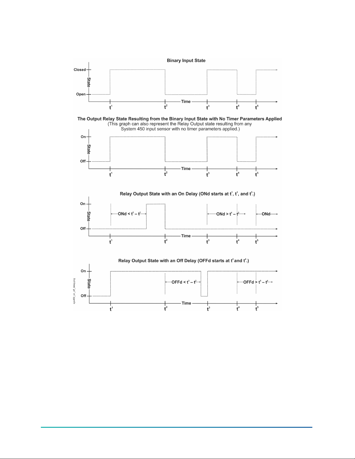
Figure 5: Behavior of a relay output referencing a binary input or other System 450
compatible sensor and the resulting output states with the on delay and off delay
parameters applied
The bottom two graphs in Figure 6 show an example of the relay output behavior when the
Minimum On or Off Time parameter is applied to the relay output (regardless of whether the relay
output references a binary input or another compatible sensor).
17System 450 Series Modular Control Systems with Standard Control Modules Technical Bulletin
Page 18
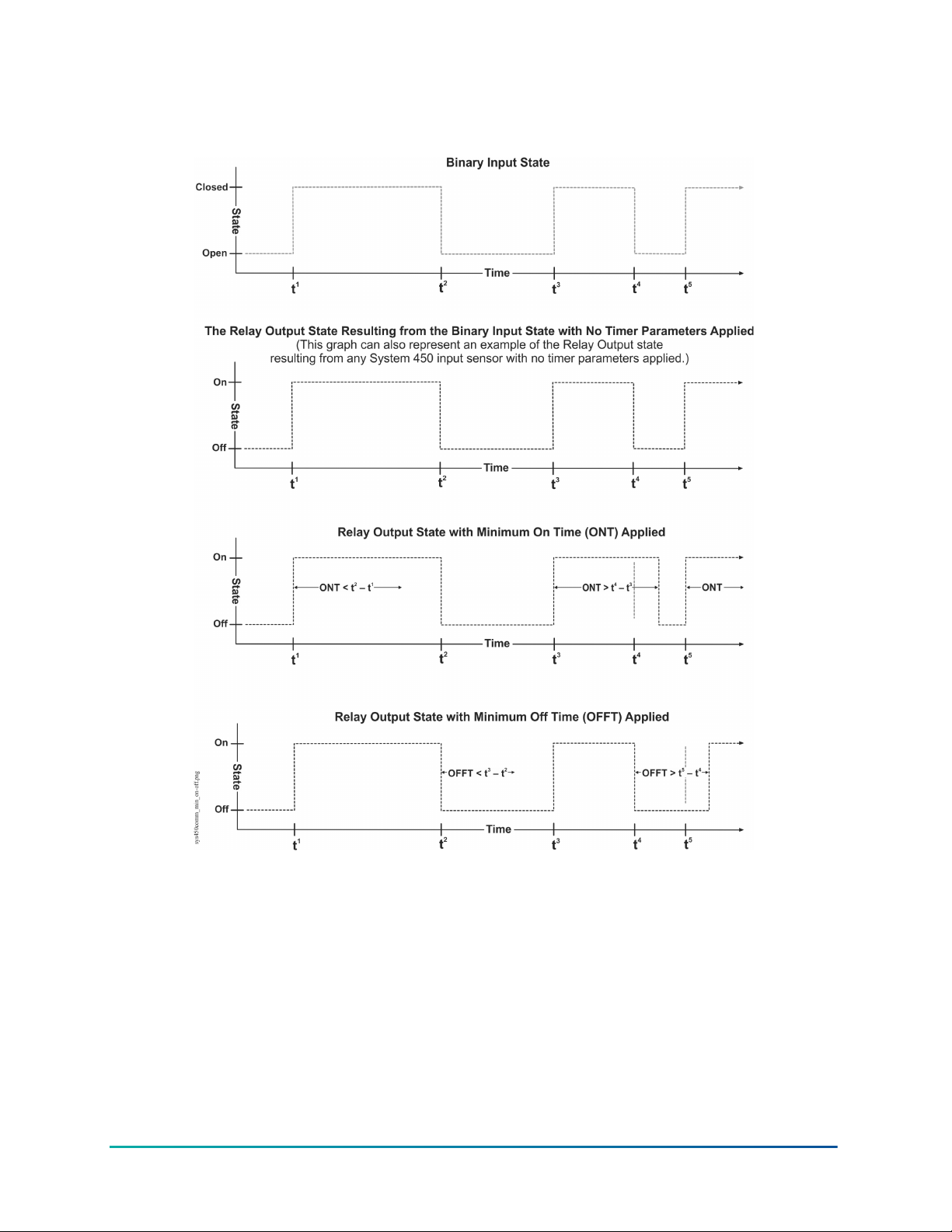
Figure 6: Behavior of a relay output referencing a binary input or other System 450 sensor
and the resulting output states with the minimum on and minimum off time parameters
applied
Analog outputs
Analog outputs provide proportional analog signals for devices and equipment in your controlled
systems. Each analog output can generate either a 4 mA to 20 mA or 0 VDC to 10 VDC signal.
The output signal type is self-selecting; after you connect the analog output to the controlled
equipment, the output detects the analog input on the controlled equipment and generates the
appropriate analog signal for the connected input.
You can set up an analog output to generate a direct-acting or reverse-acting proportional output
signal. You can also set up the output signal strength to increase or decrease in either the directacting or reverse-acting mode. See Direct and Reverse Control Actions for Analog Outputs for more
information.
System 450 Series Modular Control Systems with Standard Control Modules Technical Bulletin18
Page 19

The System 450 also provides six integration constants that allow you to set up a proportional plus
integral control signal, which can provide more precise setpoint control. See Proportional Plus
Integral Control and Integration Constants for information on determining the integration constant
for an analog output.
For procedures on setting up analog outputs on control modules, see Setting up an analog output.
The System 450 expansion modules are available with one or two analog outputs. See Table 12 and
Related Documentation for more information about the System 450 Series module models that are
used to build the control systems
Direct and reverse control actions for analog outputs
An analog output can be set up to provide one of four different control actions, which allow you to
match the output signal to the requirements of your control system and the controlled equipment.
The proportional output signal can provide direct-acting or reverse-acting control. In addition,
the output signal can be set up to generate either the minimum or the maximum output signal
strength at Setpoint.
A control ramp icon is displayed on the status screens for all analog outputs in your control system.
See Figure 1. The displayed control ramp icon represents the control action of the analog output
signal. See Table 4 for more information on analog output control actions and control ramp icons.
An analog output’s control action and the corresponding control ramp are automatically
determined by the values that you select in four analog output setup screens:
• Setpoint value (SP) is the target value that the control system drives toward, and along with
the End Point, defines the analog output’s proportional band.
• End Point value (EP) is the maximum deviation from the target value (Setpoint). The control
system applies maximum output at the EP to drive the process back toward the SP. The SP and
EP define the analog output’s proportional band.
• Output at Setpoint value (OSP) is the signal strength level of the analog output when the
input sensor is at Setpoint (SP). The OSP is expressed as a percentage (0 to 100%) of the full
scale output.
• Output at Endpoint value (OEP) is the signal strength level of the analog output when the
input sensor is at the End Point (EP). The OEP is expressed as a percentage (0 to 100%) of the
full scale output.
Note: System 450 analog outputs that reference the differential control sensor (Sn-d) use a
Differential Setpoint (dSP) and Differential End Point (dEP) to define the output’s proportional
band. See Differential Control for more information.
Table 4 shows the four control ramp icons and describes their corresponding control actions and
the setup value relationships required to configure the four control actions. See Figure 27 and
Figure 28 for examples.
19System 450 Series Modular Control Systems with Standard Control Modules Technical Bulletin
Page 20
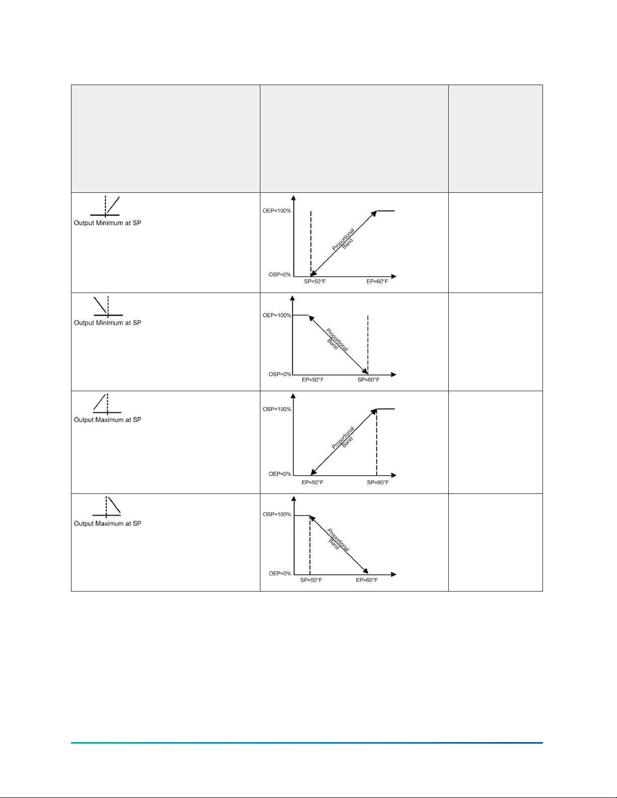
Table 4: System 450 control ramps, analog output control actions, and system setup value
relationships
Control ramp displayed Control action Set the analog
output value
relationships for
the preferred
control
action and
corresponding
control ramp
SP < EP
OSP < OEP
SP > EP
OSP < OEP
SP > EP
OSP > OEP
SP < EP
OSP > OEP
Proportional plus integral control and integration constants
In addition to standard proportional control, System 450 provides Proportional plus Integral (PI)
control capability. The addition of integral control enables a properly set up analog output to drive
a controlled condition closer to Setpoint (Figure 7).
Standard proportional-only controls continuously adjust the output in proportion to the difference
(offset error) between the setpoint value and the sensor value. As the load on the system increases,
the offset error increases. A proportional-only control responds to the increased offset error by
changing the output signal, which drives the controlled equipment to compensate for the load
change (Figure 7). Proportional-only control loops are relatively easy to set up and adjust.
System 450 Series Modular Control Systems with Standard Control Modules Technical Bulletin20
Page 21
Typically, under constant system load, proportional-only control loops do not drive a system to
the selected setpoint. Instead, the controlled system is maintained at a control point within the
proportional band (throttling range) between setpoint and end point. The larger the load on the
system, the further the control point drifts from setpoint. Still, for many applications, proportionalonly control is the best choice for analog output control.
Figure 7: Proportional-only control versus proportional plus integral control
Proportional plus Integral (PI) control incorporates a time-integral control action with
proportional control action and, if properly set up, a PI control loop can effectively eliminate offset
error and enable a controlled system to drive to setpoint even under large constant loads (Figure
7). On a properly sized system with predictable loads, PI control can maintain the controlled system
very close to setpoint.
A system’s output capacity, the size of the load on the system, and the integration constant
selected determine the speed (recovery rate) at which the PI control drives the system to setpoint.
The integration constant establishes the rate at which the control readjusts the analog output
signal. The faster the integration constant, the faster the control readjusts the output signal and the
faster the recovery rate of a properly sized and setup control loop.
Note: PI control is not suitable for all controlled systems. Improperly applied PI control
loops are unstable and can overshoot setpoint, resulting in control loop oscillation. Also,
with PI control, the proportional band (throttling range) and the integration constant are
interdependent and you must properly set up these values in relation to each other. You must
also properly size the system equipment to handle the maximum load. Close observation over
several cycles and under different load condition is required to properly set up a PI control
loop. On a properly sized system, a PI control loop can drive the system condition much closer
to setpoint than proportional-only control.
In addition to a proportional-only setting, System 450 provides six time-integral settings in
the Integration Constant Setup screen for matching the analog signal’s response rate to the
controlled system’s recovery rate. The seven integration constant settings are shown in Table 9.
See Determining the Integration Constant for an Analog Output for more information and the
procedures for determining an integration constant and testing a PI control loop in your controlled
system.
21System 450 Series Modular Control Systems with Standard Control Modules Technical Bulletin
Page 22

The Analog Output Update Rate and Output Deadband contain two parameters that can be used
to minimize the frequency of changes to the output signal from the control. When controlling a
device such as an actuator, these features can lengthen the actuator life by reducing the actuator
position update frequency. See Analog Output Update Limiters and Analog Output Deadband for
more information.
Analog output update limiters
The Output Update Rate and Output Deadband minimize the frequency of changes to the output
signal from the control. When controlling a device such as an actuator, these features can lengthen
actuator life by reducing the actuator position update frequency.
Analog output update rate
The output update rate feature allows you to select the rate, in seconds, during which the control
does not allow an update to the analog output’s signal strength. The Output Update Rate value
range is 1 to 240 seconds and the default value is 1 second.
The Output Update Rate and Output Deadband are used to minimize the frequency of changes to
the output signal from the control. When controlling a device such as an actuator, these features
can lengthen actuator life by reducing the actuator position update frequency.
The System 450 control module calculates the input-induced output signal strength once per
second. The default Output Update Rate is one second. The actual output signal strength is
updated to the calculated output signal strength once every second when the control is set to the
default update value. In some control applications, a 1-second update rate may be too frequent and
may result in premature wear on the controlled equipment, such as actuators.
When you select an Output Update Rate value greater than 1 second, the control module delays
updating the output and maintains the output signal strength for the duration of the selected
update rate. At the end of the selected update rate, the control updates the output signal strength
to the current calculated output signal strength and maintains the new output signal strength value
for the selected output update rate value.
For example, if you select an Output Update Rate value of 5 (seconds), the control module updates
the output signal strength every 5 seconds, reducing changes at the controlled equipment to 20%
of the default update rate. See Figure 8.
System 450 Series Modular Control Systems with Standard Control Modules Technical Bulletin22
Page 23
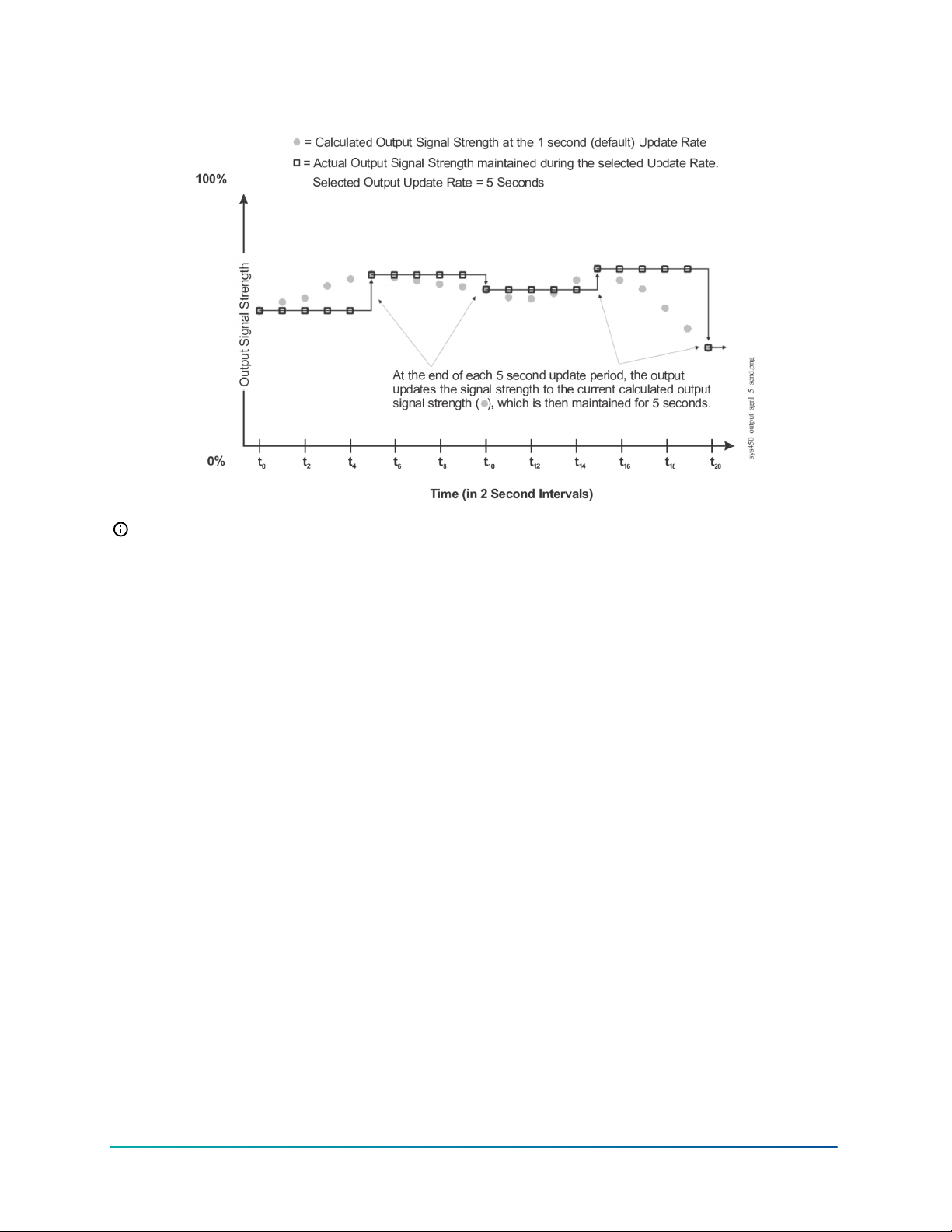
Figure 8: Graph showing calculated output signal strength and output signal strength
maintained by a 5-second update rate
Note: The Output Update Rate feature can be used in conjunction with the Output Deadband
feature, but care must be taken when selecting these values for your control system. In
process loops where the condition (temperature, pressure, or humidity) value can change
quickly over a large range, the delay in updating the actual output signal strength can cause
the controlled equipment to oscillate out of range and drive the process away from the desired
setpoint. After selecting new Output Update Rate and Output Deadband values, observe
your controlled system through several cycles to determine the affect of the new values. If
the calculated output signal strength is 0 or 100%, the actual output signal strength changes
immediately.
Analog output deadband
The Output Deadband feature allows you to establish a deadband value around the calculated
output signal strength. The Output Deadband value is expressed as a percent of the output signal
strength range. The Output Deadband value range is 0 to 50 (percent of the OSP to OEP range) and
the default value is 0 (percent).
The Output Update Rate and Output Deadband are used to minimize the frequency of changes to
the output signal from the control. When controlling a device such as an actuator, these features
can lengthen actuator life by reducing the actuator position update frequency.
The System 450 control module responds to a changing input signal and updates the analog
output’s calculated output signal strength at the rate selected in the Output Update Rate screen. At
each update of the calculated output signal strength, the control determines if the new calculated
output signal strength is within the selected Output Deadband or not.
If the calculated output signal strength is within the selected Output Deadband, the actual output
signal strength is not updated and remains unchanged.
If the calculated output signal falls outside the Output Deadband, the actual output signal strength
is updated, and the selected Output Deadband is applied to the new output signal strength value.
See Figure 9.
23System 450 Series Modular Control Systems with Standard Control Modules Technical Bulletin
Page 24
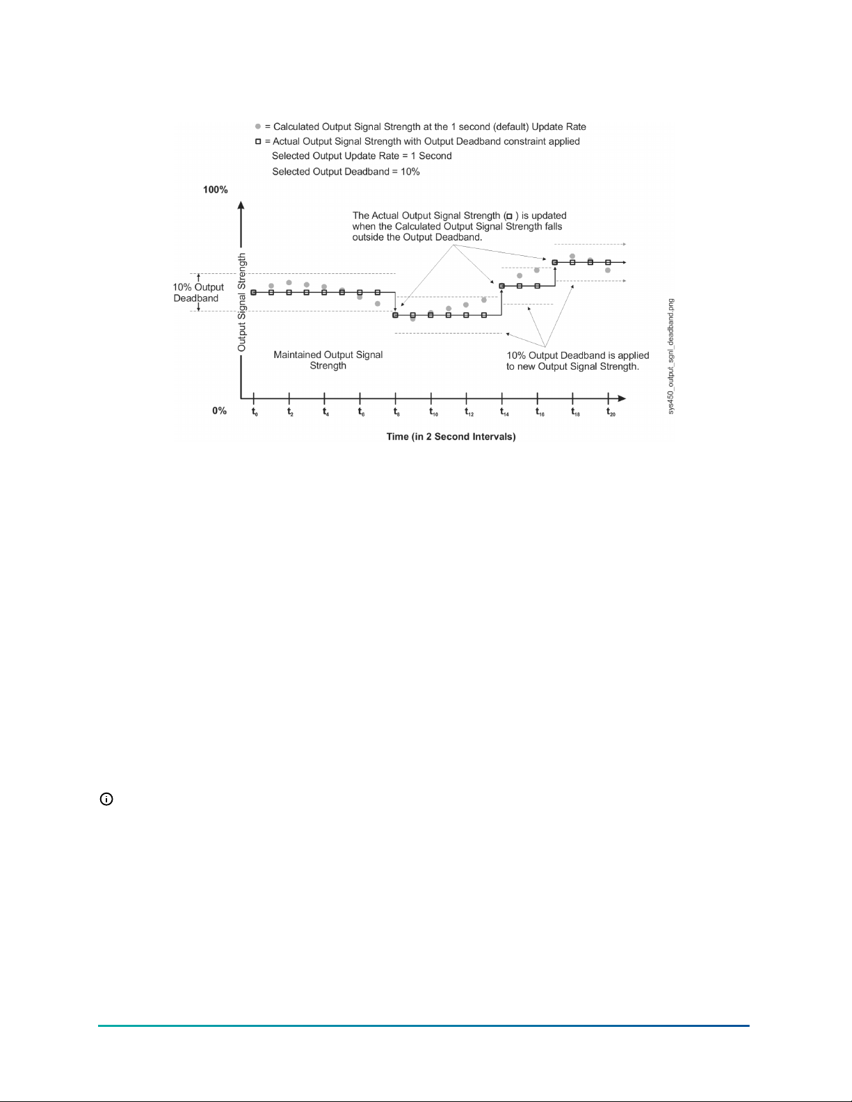
Figure 9: Graph showing calculated output signal strength and output signal strength
constrained by output signal deadband
The Output Deadband feature can be used in conjunction with the Output Update Rate feature, but
care must be taken when selecting these values for your control system. In process loops where
the condition (temperature, pressure, or humidity) value can change quickly over a large range, the
delay in updating the actual output signal strength can cause the controlled equipment to oscillate
out of range and drive the process away from the desired setpoint. After selecting new Output
Update Rate and Output Deadband values, observe your controlled system through several cycles
to determine the affect of the new values. If the calculated output signal strength is 0 or 100%, the
actual output signal strength changes immediately.
High input signal selection
The High Input Signal Selection feature enables a System 450 control system to monitor a
temperature, pressure, or humidity condition with two or three sensors of the same type and
control relay and analog outputs based on the highest condition value sensed by the two or three
referenced sensors.
When Sn-1 and Sn-2 are set up with the same Sensor Type, the functional High Input Signal
Selection sensor (HI-2) is available for selection when you set up the outputs in the control system.
When Sn-1, Sn-2, and Sn-3 are set up with the same Sensor Type, the functional sensor (HI-3) is also
available for selection.
Note: Setting up Sn-1 and Sn-2 as the same Sensor Types also enables the functional
Differential Control sensor (Sn-d). See Differential Control for more information.
High Input Signal Selection control application examples include:
• fan-staging control on multi-circuit condensing units
• fan motor speed control on multi-circuit condensing units
Differential control
The Differential Control feature enables a System 450 control system to monitor and maintain a
temperature, pressure, or humidity differential between two sensors of the same type and control
System 450 Series Modular Control Systems with Standard Control Modules Technical Bulletin24
Page 25
relay, analog outputs, or both based on the sensed differential value relative to user-selected
differential values.
Differential Control application examples include:
• solar heating systems
• pump pressure-drop monitoring and control
• fluid filter pressure-drop monitoring
• air filter pressure-drop monitoring
Setting up an output (relay or analog) for Differential Control requires connecting two identical
sensors to input terminals Sn1 and Sn2 and selecting the same Sensor Type in the System 450 UI
for Sensor 1 (Sn-1) and Sensor 2 (Sn-2). The System 450 control system recognizes the same Sensor
Types and makes the functional Differential Control sensor (Sn-d) available for selection when you
set up each of the control system outputs.
Note: Setting up Sn-1 and Sn-2 as the same Sensor Types also enables the functional High
Input Signal Selection sensor (HI-2). See High Input Signal Selection for more information.
When a Differential Control sensor (Sn-d) is set up, the differential sensor value is always equal to
Sn-1 minus Sn-2. Therefore, depending on the intended control action of the output, the differential
value may be either a positive or negative value.
The sensed differential value (Sn-d) between Sn-1 and Sn-2 is displayed in the System Status
screens as either a temperature differential value (dIFT), pressure differential value (dIFP),
or humidity differential value (dIFH). The unit of measurement associated with the displayed
differential value is determined by the Sn-1 and Sn-2 Sensor Type. See Table 5 for Sensor Types and
their units of measurement.
When a relay output is set up for Differential Control, System 450 compares the sensed differential
value, Sn-d (Sn-d = Sn-1 minus Sn-2), to the user-selected differential values (dON and dOFF) to
control the relay’s On/Off state.
When an analog output is set up for Differential Control, System 450 compares the sensed
differential value, Sn-d (Sn-d = Sn-1 minus Sn-2), to the user-selected differential values (dSP and
dEP) to control the analog output signal strength.
Note: Because of the way that the System 450 Differential Sensor (Sn-d) is set up and
calculated using two sensors with identical Sensor Types, the Range of Usable Values for each
Sensor Type is twice as large as a single sensor. (Each Sensor Type has an equal number of
positive and negative values on outputs that reference Sn-d.) See Table 5 for a Sensor Type’s
Range of Usable Values when an output references Sn-d.
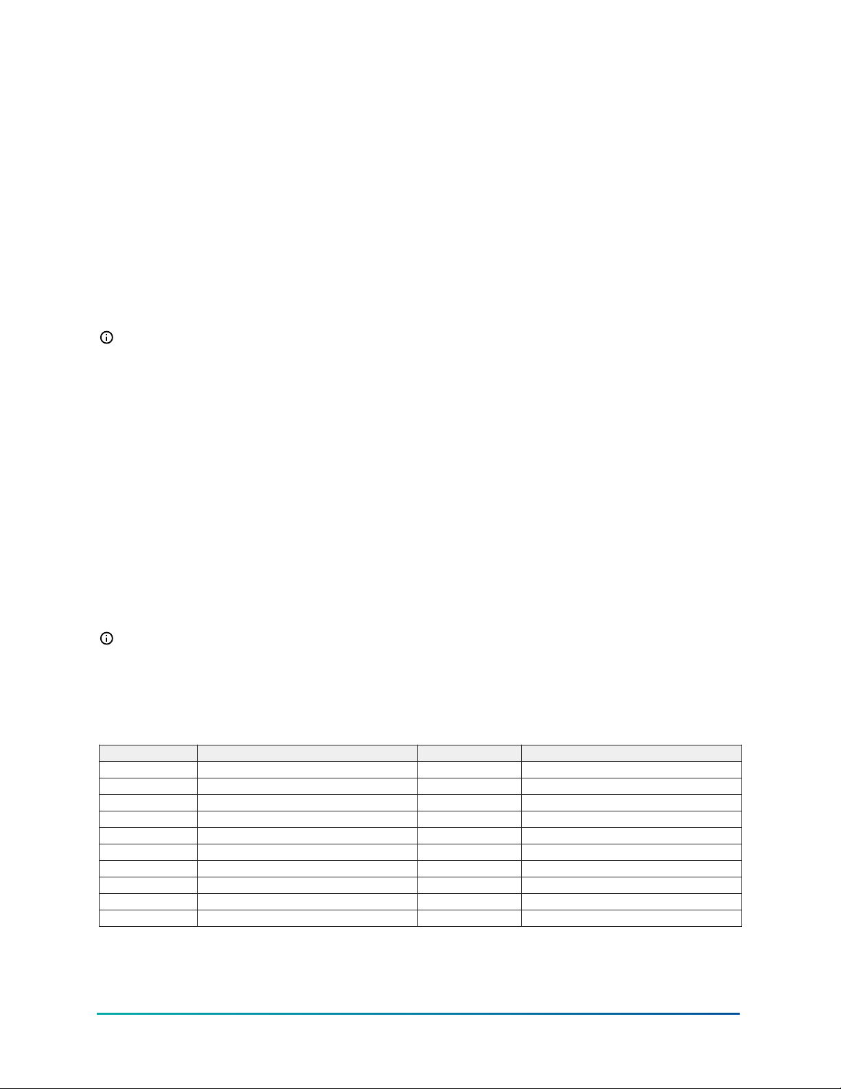
Table 5: Range of usable values for sensor types in differential control applications
Sensor type Sn-d range of usable values Sensor type Sn-d range of usable values
°F -290 to 290 P 30 -30.0 to 30.0
°C -161.0 to 161.0 P 50 -50.0 to 50.0
rH -95 to 95 P 100 -100.0 to 100.0
P 0.25 -0.500 to 0.500 P 110 -110.0 to 110.0
P 0.5 -0.500 to 0.500 P 200 -200 to 200
P 2.5 -2.50 to 2.50 P 500 -500 to 500
P 5 -5.00 to 5.00 P 750 -750 to 750
P 8 -9.00 to 9.00 HI°F -380 to 380
P 10 -10.00 to 10.00 HI°C -210.0 to 210.0
P 15 -16.0 to 16.0 -- --
25System 450 Series Modular Control Systems with Standard Control Modules Technical Bulletin
Page 26

Sensor Failure mode
System 450 allows you to select the mode of operation for your control system outputs in the event
of a sensor (or sensor wiring) failure of the sensor or sensors that the outputs reference. When
you set up an output in the System 450 UI, you must select a sensor failure mode of operation
in the Sensor Failure Mode (SNF) screen. Your selection determines how an output responds if a
referenced sensor or the sensor wiring fails.
System 450 outputs can be set up to directly reference a single compatible sensor hardwired to
the control system (Sn-1, Sn-2, or Sn-3). Outputs in control systems with System 450 standard
control modules can also be set up to reference several functional sensors (Sn-d, HI-2, or HI-3). The
functional sensors reference input from one or more of the hard-wired sensors; thus one or more
of the hard-wired sensors can influence the outputs that reference functional sensors.
When any one of the connected sensors (Sn-1, Sn-2, or Sn-3) or associated sensor wiring fails, all
of the outputs that reference the failed sensor, either directly or through a functional sensor, go
into the outputs’ selected sensor failure modes and continue to operate in the sensor failure modes
until the sensor or sensor wire failure is corrected.
You can select either On or OFF for an output’s Sensor Failure Mode. Depending on the type of
output (relay or analog), the On and OFF Sensor Failure Modes are defined as follows:
• Relay output SNF On = Relay On. See Relay Outputs for more information about a relay
output’s On state.
• Relay output SNF OFF = Relay OFF. See Relay Outputs for more information about a relay
output’s Off state.
• Analog output SNF On = Output Signal Strength at End Point (OEP). See Direct and Reverse
Control Actions for Analog Outputs for more information about Output Signal at End Point.
• Analog output SNF OFF = Output Signal Strength at Setpoint (OSP). See Direct and Reverse
Control Actions for Analog Outputs for more information about Output Signal at Setpoint.
System 450 control system examples
With System 450 control and expansion modules, you can build a wide variety of cost-effective,
custom control systems. Each of the following examples provide an illustration of the module
assembly, including wiring diagrams for system sensors and outputs, and menu flow charts
showing typical Main screens and System Status screens, along with System Setup screens and
example setup values.
Note: The physical configurations, wiring, and setup values shown in the following examples
are meant to illustrate typical control system applications, control features, and system setup
values. Your control applications may require different modules, module configurations,
sensors, wiring, and UI setup parameters and values.
See Control Module and User Interface and Expansion Modules, Module Assemblies, and Outputs
for general information and guidelines about System 450 modules and UI. See Figure 10 for
information and procedures about how to design your control system, select modules and sensors,
mount and wire your control system, access and navigate the System 450 UI, and set up your
control system in the UI.
Control system example
The following table shows an example System 450 control system module assembly and the (userinstalled) field wiring for a cooling application with condenser fan speed control. Figure 11 shows
the System 450 UI menu flow for monitoring and setting up the control application shown in Figure
10.
System 450 Series Modular Control Systems with Standard Control Modules Technical Bulletin26
Page 27
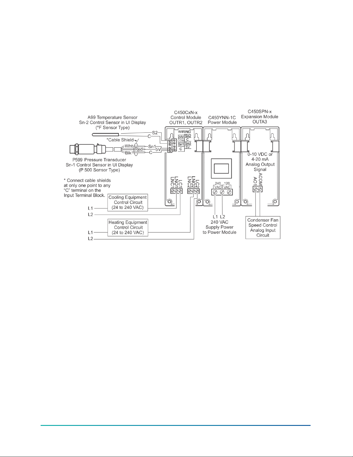
Figure 12 shows a temperature, humidity, and pressure System 450 control system example, the
module positions, the output types, and the automatically assigned output numbers used in the
System Setup screens in the control module UI. Figure 13 shows the corresponding Main, System
Status, and Setup Screens.
Figure 14 shows a System 450 control system example for a solar water heating and storage
application that uses the Differential Control feature to control two circulation pumps. Figure 15
shows the corresponding Main, System Status, and Setup Screens.
Figure 10: Example of a System 450 control showing for a room heating and cooling
application with condenser fan speed control
27System 450 Series Modular Control Systems with Standard Control Modules Technical Bulletin
Page 28
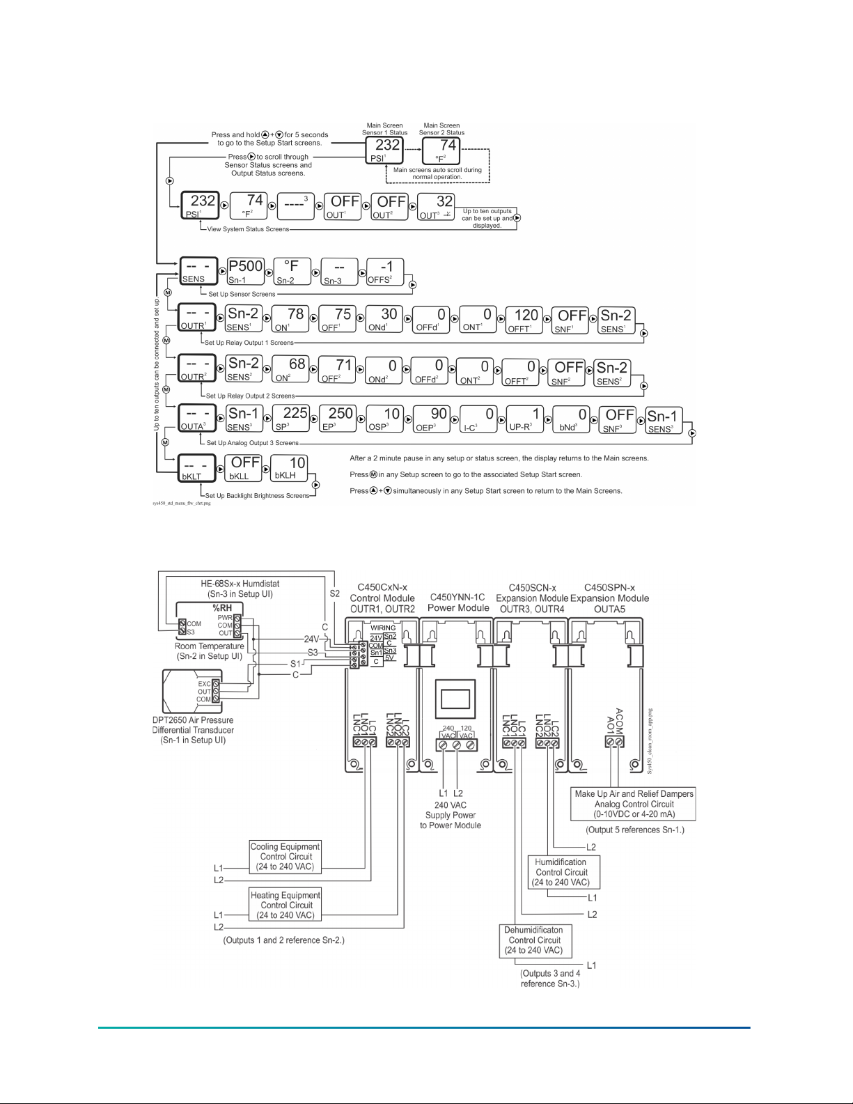
Figure 11: Main, System, Status, and Setup Screens for a room heating and cooling
application with condenser fan speed Control
Figure 12: Example of a System 450 standard control for a clean room application that
controls temperature, pressure, and humidity simultaneously
System 450 Series Modular Control Systems with Standard Control Modules Technical Bulletin28
Page 29
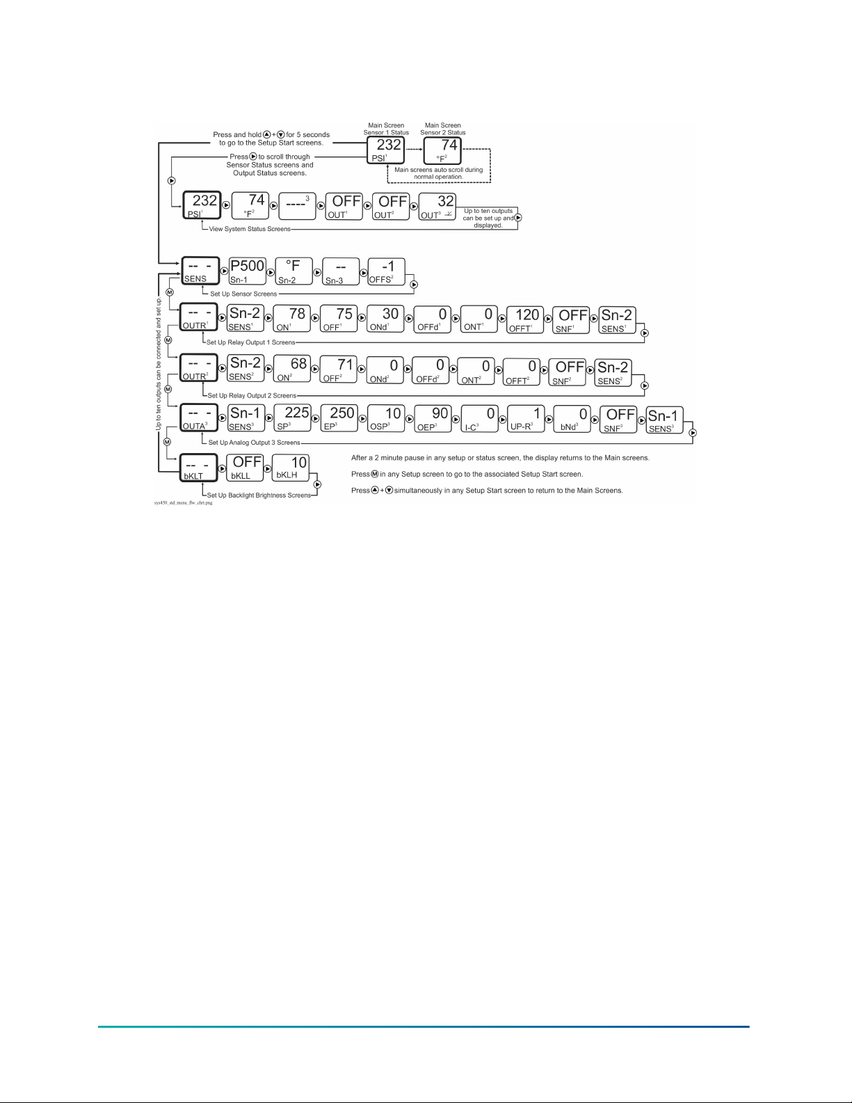
Figure 13: Main, System Status, and Setup Screens for a clean room application that controls
temperature, pressure, and Humidity Simultaneously
29System 450 Series Modular Control Systems with Standard Control Modules Technical Bulletin
Page 30
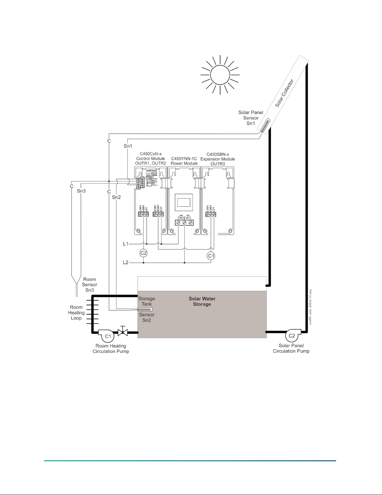
Figure 14: Example System 450 standard control showing a solar water space heating
application that uses the differential control feature
System 450 Series Modular Control Systems with Standard Control Modules Technical Bulletin30
Page 31
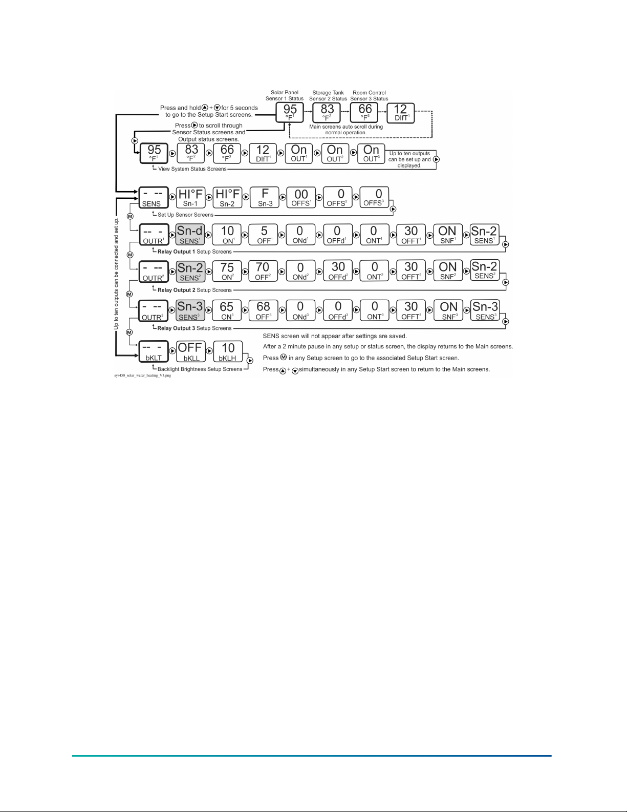
Figure 15: Main, System Status, and Setup Screens for a solar water heating control system
example that uses the differential control feature
Hybrid analog and high input signal selection control system example
Figure 16 shows a System 450 Hybrid Analog Output Control System example using a C450CPW-400
control module with the hybrid analog output controlling the speed of the Electronically
Commutated (EC) fan motor for cooling based on condenser pressure.
This example uses two P599 Pressure Transducers and the High Input Signal Selection feature to
control the condenser fan speed based on the highest pressure sensed by the two transducers. The
cooling equipment is controlled by an A99 temperature sensor.
Figure 16 also shows a C450 control system that is set up to use the High Input Signal Selection
feature to control the hybrid analog output signal and the motor speed of an EC fan motor on the
cooling equipment condenser.
Figure 17 shows the System 450 UI Main screens, System Status screens, and System Setup screens
for the control system example in Figure 16.
31System 450 Series Modular Control Systems with Standard Control Modules Technical Bulletin
Page 32
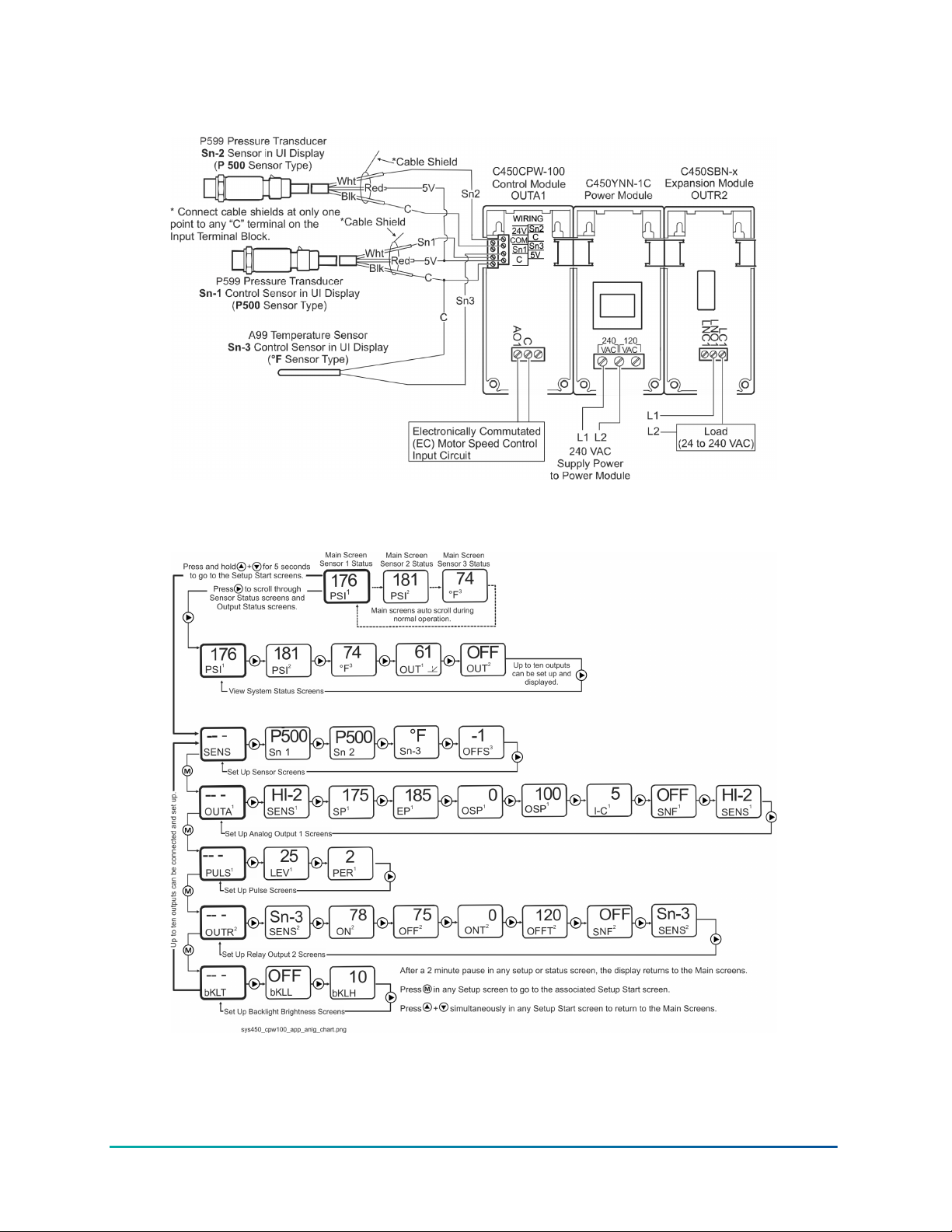
Figure 16: System 450 hybrid analog output control system example with condenser fan (EC)
motor speed control, high input signal selection
Figure 17: Main, System Status, and Setup Screens for a hybrid analog output control system
example with high input signal selection
System 450 Series Modular Control Systems with Standard Control Modules Technical Bulletin32
Page 33

Designing and building System 450 control systems
The variety and flexibility of System 450 modules and sensors allow you to build an almost
limitless variety of custom control systems. In fact, for many control systems, different System 450
components can be configured to achieve the same results.
Observe the following guidelines when designing a control system and selecting components for
your control system:
• Determine the conditions and condition ranges that must be monitored and controlled in your
application to determine the sensors you need. Up to three sensors can be connected and up
to three conditions can be monitored simultaneously using standard control modules. See
Table 2 and Selecting, Installing, and Setting Up Sensors for more information.
• Determine the type of control your application requires—standard control, relay control,
analog proportional control, Differential Control, High Input Signal Selection, multi-purpose,
or a combination of control types. See System 450 Control Systems with Standard Control
Modules for more information regarding System 450 control types.
• Select the standard control module or hybrid analog output control module if your application
requires on/off relay control, proportional analog control, multi-stage control, multi-purpose
control, stand-alone control, or proportional plus integral control. (See Table 12 for System 450
control module model information.)
• Determine the number and type (relay or analog) of outputs required to control the
equipment in your application. Up to ten outputs can be configured and controlled by a single
System 450 control module.
• Determine the types of control and expansion modules (relay or analog) needed to provide
the required outputs for your application and the minimum number of modules required to
provide those outputs.
Note: Many System 450 control systems can be configured using different combinations of
module models to build the assembly, but typically there is one combination of modules that is
more cost effective to build than other potential module assembly configurations.
Selecting, installing, and setting up sensors
In a System 450 control system, all of the outputs reference one or more of the sensors that are
wired to the control module and set up in the control module UI. Observe the following guidelines
when you select, install, and set up sensors for your control system:
• Select only System 450 compatible sensors. See Table 5 for a complete list of System 450
sensor types and models that are compatible with standard control modules. See Table 14
through Table 18 in Repair and Ordering Information for more information about System 450
compatible sensors.
• Select only the sensors that match the desired conditions and units of measurement, and are
designed to operate in the ranges that your control system is intended to monitor and control.
• Ensure that the correct sensor is wired properly to the correct input terminals on the control
module. See Wiring System 450 Components.
• Ensure that the wire length between the sensors and control module is as short as possible
or practical, and ensure that the wiring is properly sized. Refer to the sensor installation
instructions referenced in System 450 Overview for more information on wiring sensors.
33System 450 Series Modular Control Systems with Standard Control Modules Technical Bulletin
Page 34

• Ensure that the correct sensor type is selected in the System 450 UI for each sensor wired to
the control module. See Setting Up the Sensors and Transducers.
• Ensure that each output references the correct sensor in the System 450 UI. See Setting up a
System 450 Control System.
Assembling System 450 modules
After selecting the System 450 components for your control system, you must assemble the
modules. Figure 2 shows an example of a System 450 module assembly.
Observe the following guidelines when assembling System 450 modules:
• Always locate the control module on the left side of the module assembly.
• Always plug the System 450 power module when used into the right side of the control
module.
• Plug the expansion modules together, in any order, on the right side of the System 450 power
module or on the right side of the control module when an external 24 V power supply is used
instead of a System 450 power module. See Wiring System 450 Components for information
on wiring an optional external 24 VAC supply power to System 450 control systems that do not
include a power module.
Locating System 450 modules
Observe these guidelines when locating and mounting System 450 modules:
• Ensure that the mounting surface can support the module assembly, DIN rail, mounting
hardware, and any user-supplied panel or enclosure.
• Mount the modules in a horizontal, upright orientation wherever possible. DIN rail mounting is
strongly recommended.
• In direct-mount applications, mount the modules on flat and even surfaces.
• Mount the modules in a location free of corrosive vapors and observe the ambient operating
conditions in the Related Documentation.
• Leave sufficient space for making connections, running wires, and viewing the LCD.
• Do not mount the modules on surfaces that are prone to vibration or in locations where highvoltage relays and motor-starters, electromagnetic emissions, or strong radio frequency may
cause interference.
• Do not install heat generating devices in an enclosure with the modules that may cause the
ambient temperature to exceed 66°C (150°F).
Mounting
Mount System 450 modules on 35 mm DIN rail (recommended) or directly to a flat, even surface.
Mounting modules on DIN rail
About this task: To mount the modules on DIN rail, complete the following steps:
1. Provide a section of 35 mm DIN rail that is longer than the module assembly width, and
mount the DIN rail in a suitable location using appropriate mounting hardware.
System 450 Series Modular Control Systems with Standard Control Modules Technical Bulletin34
Page 35
2. Clip the control module on the rail, position the module’s upper DIN rail clips on the top rail,
and gently snap the lower clips on to the bottom of the rail.
Important: When mounting a module assembly on a DIN rail, clip the modules on to the DIN
rail individually before gently sliding and plugging the mounted modules together on the DIN
rail. Clipping a complete module assembly that is already plugged together on to the DIN rail
can damage the 6-pin modular plugs and void any warranties.
3. Clip the remaining modules to the right of the control module on to the DIN rail and gently
slide and plug the modules together. If a System 450 power module is used, mount the power
module on the right side of the control module so that the power module plugs directly into
the control module.
Direct-mounting modules
About this task:
To direct-mount modules to walls and other flat surfaces using the four keyhole slots, complete the
following steps:
1. Plug the modules together, remove the module covers, place the module assembly
horizontally against the wall surface in a suitable location, and mark the mount hole locations
on the mounting surface
2. Install appropriate screws or fasteners, leaving the screw heads approximately one to two
turns away from flush to the mounting surface.
3. Position the assembly mounting slots over the screw heads, and then carefully tighten the
mounting screws to secure the assembly to the surface.
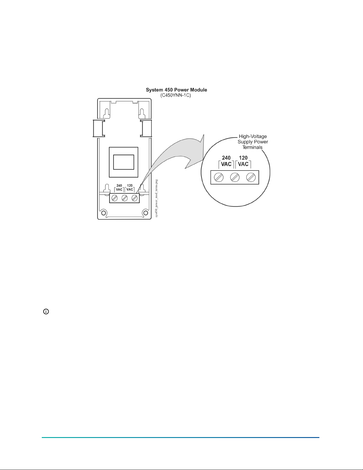
Note: If you mount the modules on an uneven surface, use shims or washers to mount
module assembly evenly on the surface.
Refer to the sensor installation instructions referenced in System 450 Overview for
information on locating and mounting System 450 compatible sensors.
Wiring System 450 components
When wiring your System 450 control system, observe the following guidelines. See Figure 18,
Figure 19, and Figure 20 for wiring terminal locations and designations. See Related Documentation
for the electrical ratings for System 450 modules used to built System 450 standard control systems.
WARNING
Risk of Electric Shock
Disconnect or isolate all power supplies before making electrical connections. More than one
disconnection or isolation may be required to completely de-energize equipment. Contact with
components carrying hazardous voltage can cause electric shock and may result in severe personal
injury or death.
35System 450 Series Modular Control Systems with Standard Control Modules Technical Bulletin
Page 36
AVERTISSEMENT
Risque de décharge électrique
Débrancher ou isoler toute alimentation avant de réaliser un branchement électrique. Plusieurs
isolations et débranchements sont peut-être nécessaires pour -couper entièrement l'alimentation
de l'équipement. Tout contact avec des composants conducteurs de tensions dangereuses risque
d'entraîner une décharge électrique et de provoquer des blessures graves, voire mortelles.
Important: Use copper conductors only. Make all wiring connections in accordance with local,
national, and regional regulations. Do not exceed the System 450 module's electrical ratings.
Important: Do not exceed the System 450 module electrical ratings. Exceeding module
electrical ratings can result in permanent damage to the modules and void any warranty.
Important: Run all low-voltage wiring and cables separate from all high-voltage wiring.
Shielded cable is strongly recommended for input (sensor) and analog output cables that are
exposed to high electromagnetic or radio frequency noise.
Important: Make all wiring connections in accordance with the National Electrical Code and
local regulations. Use proper Electrostatic Discharge (ESD) precautions during installation and
servicing to avoid damaging the electronic circuits of the System 450 modules.
Important: Do not connect supply power to the System 450 modules before checking all
wiring connections. Short circuits or improperly connected wires can result in damage to the
modules and void any warranty.
Important: A System 450 control module and module assembly can be connected to an
internal power source (a System 450 power module) or an external power source (24 V power
connected to the 24V and COM terminals on the control module), but must not be connected
to both power sources simultaneously. Connecting a control module to both internal and
external power sources can damage the modules and void any warranty.
System 450 Series Modular Control Systems with Standard Control Modules Technical Bulletin36
Page 37
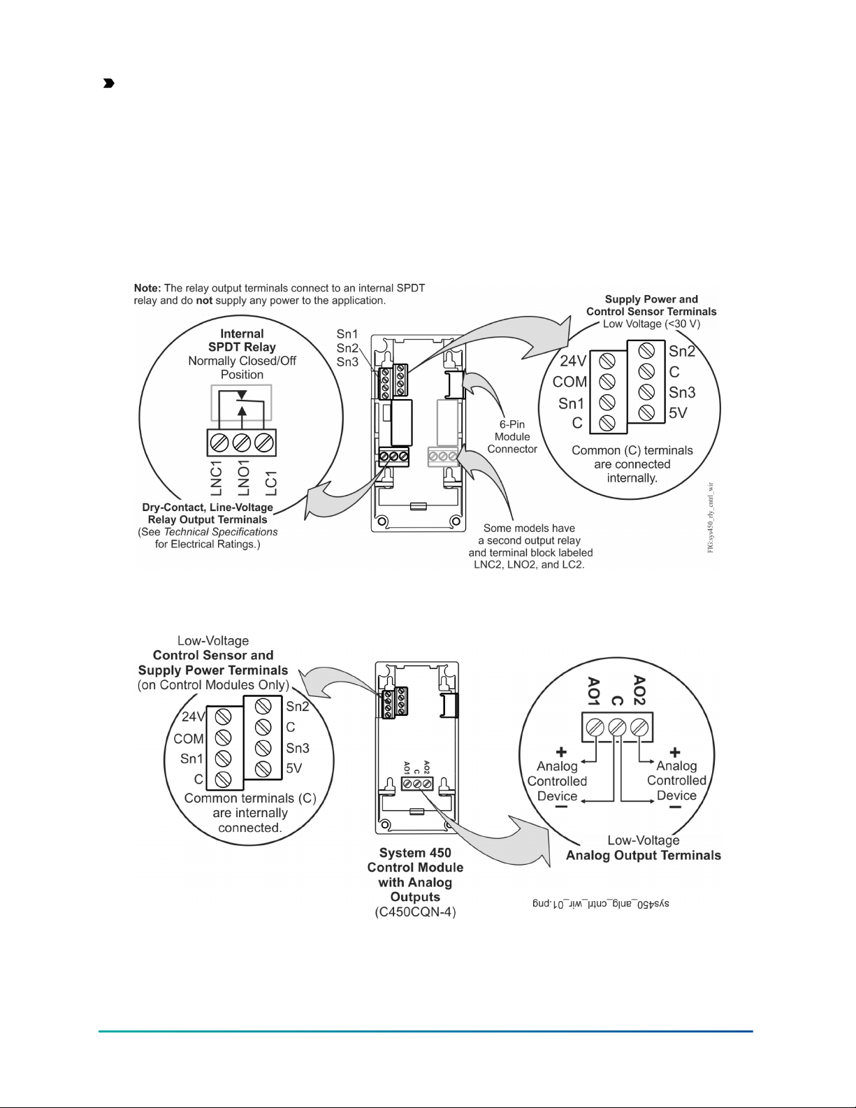
Important: When connecting System 450 compatible sensors with shielded cable to a System
450 control module, connect the cable shield drain lead to one of the C (common) terminals on
the input sensor terminal block. Do not connect the shield at any other point along the cable.
Isolate and insulate the shield drain at the sensor end of the cable. Connecting a cable shield
at more than one point can enable transient currents to flow through the sensor cable shield,
which can cause erratic control operation.
Figure 18 and Figure 19 show the locations of and designations for the wiring terminals for System
450 standard control modules and expansion modules.
Figure 18: Wiring Terminal Details for System 450 Control and Expansion Modules with Relay
Output
Figure 19: Wiring Terminal Details for System 450 Control and Expansion Modules with
Analog Outputs
Table 6 provides descriptions, ratings, requirements, and recommended cable types and
recommended wire sizes for System 450 standard control, expansion, and power modules.
37System 450 Series Modular Control Systems with Standard Control Modules Technical Bulletin
Page 38
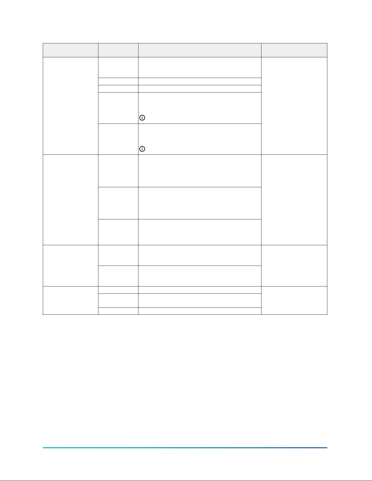
Table 6: System 450 wiring terminal and wire size information
Terminal block type
on module type
Sensor and low-voltage
supply power terminal
block on all control
modules
Line-voltage output
relay terminal blocks
on control and
expansion modules
with relay output)
Low-voltage analog
output terminal
block on control and
expansion modules
with analog outputs
Line-voltage supply
power terminal block
on power modules only
Terminal label Terminal function Required wire sizes
24 V Provides power terminal for active 24VAC humidity
sensors when a C450YNN power module is
connected.
5 V Provides 5 VDC power for active sensors.
Sn1, Sn2, Sn3 Accepts passive or active input signals from sensors.
C Provides low-voltage common connections for
passive or active sensors connected to the 5V, Sn1,
Sn2, and Sn3 terminals.
Note: The terminals are connected internally.
COM Provides low-voltage common connections for 24
VAC power connected to the 5V, Sn1, Sn2, and Sn3
terminals.
Note: The terminals are connected internally.
LNC1,
LNC2
Connects equipment control circuit to the line-
voltage Normally Closed (LNC) contact on the SPDT
relay.
LNC2 terminals are only on control and expansion
modules with two output relays.
LNO1,
LNO2
Connects equipment control circuit to the line-
voltage Normally Open (LNO) contact on the SPDT
relay.
LNO2 terminals are only on control and expansion
modules with two output relays.
LC1
LC2
Connects line power to the line-voltage Common (LC)
on the SPDT relay.
LC2 terminals are only on control and expansion
modules with two output relays.
AO1
AO2
In conjunction with the COM terminal, provides a
self-detecting analog output signal; either 0 to 10
VDC or 4 to 20 mA.
ACOM In conjunction with the AO1 or AO2 terminal,
provides a self-detecting analog output signal; either
0 to 10 VDC or 4 to 20 mA.
240 VAC Left terminal is for one 240 VAC supply power lead.
No Label on the
Middle Terminal
Middle terminal is the Common connection for either
the 120 VAC or 240 VAC supply power lead.
120 VAC Right terminal is for one 120 VAC supply power lead.
0.08 mm2 to 1.5 mm
28 AWG to 16 AWG
0.08 mm2 to 2.5 mm
28 AWG to 14 AWG
0.08 mm2 to 1.5 mm
28 AWG to 16 AWG
0.34 mm2 to 2.5 mm
22 AWG to 14 AWG
2
2
2
2
Figure 20 shows the location of and designations for the wiring terminals on a C450YNN-1C power
module. Table 7 provides descriptions, ratings, requirements, and recommended wire sizes for a
C450YNN-1C power module.
System 450 Series Modular Control Systems with Standard Control Modules Technical Bulletin38
Page 39
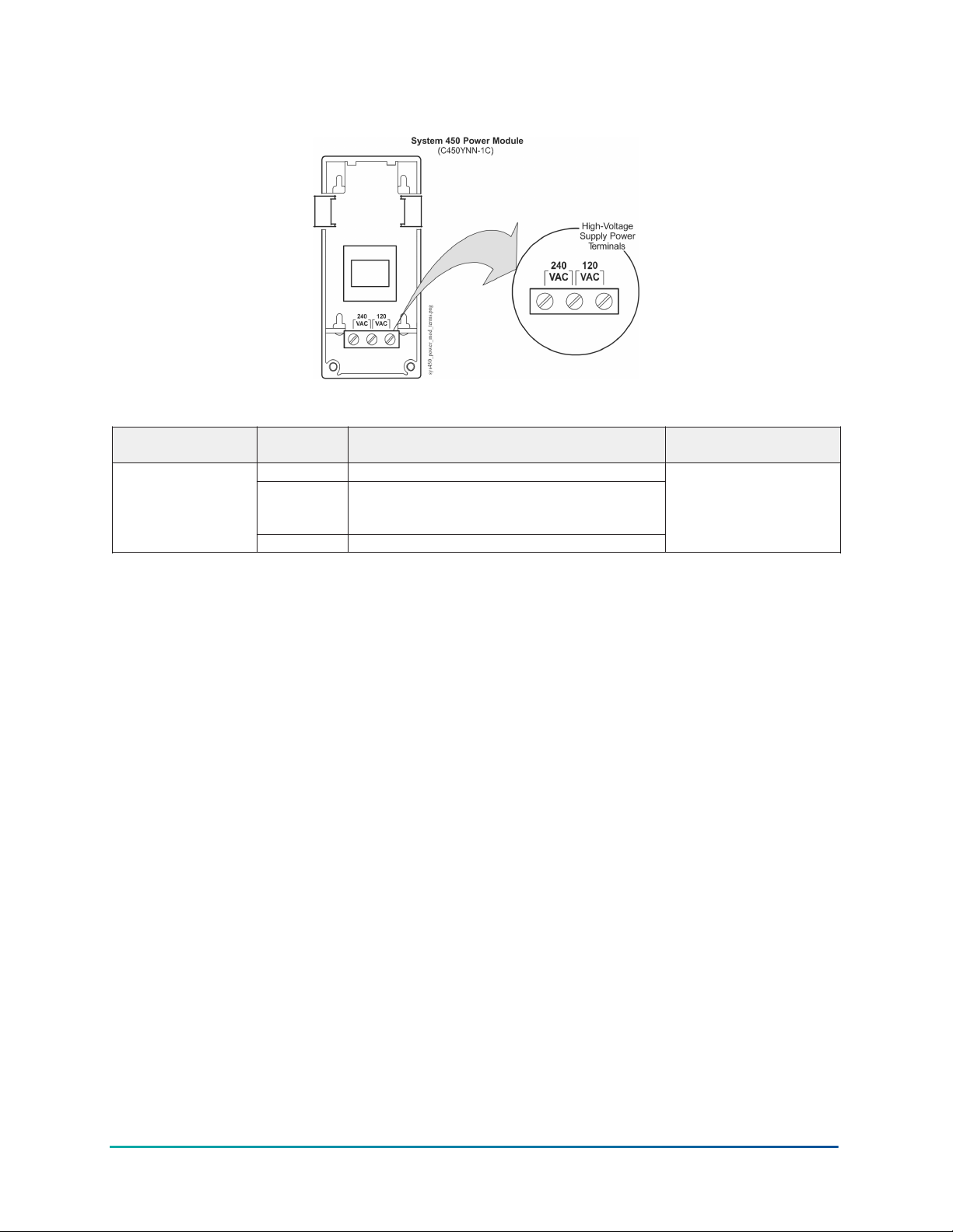
Figure 20: System 450 C450YNN-1C Power Module showing high-voltage supply power
terminals
Table 7: System 450 Power Module wiring terminal and wire size information
Terminal block type
on module type
Line-voltage supply
power terminal block
on power modules
Terminal label Terminal function Required wire sizes
240 VAC Left terminal is for one 240 VAC supply power lead.
No Label on
the Middle
Terminal
120 VAC Right terminal is for one 120 VAC supply power lead.
Middle terminal is the Common connection for either
the 120 VAC or 240 VAC supply power lead.
0.34 mm2 to 2.5 mm
22 AWG to 14 AWG
2
Wiring System 450 sensors and transducers
Refer to the sensor installation instructions referenced in System 450 Overview for information on
wiring System 450 compatible sensors.
Setting up a System 450 control system
After assembling the modules, your System 450 control system is ready to connect to power and to
be set up in the control module UI.
• You can power on and set up your System 450 control system in the control module UI before
installing the module assembly or wiring the sensors and outputs.
• The sensors or transducers must be set up in the System 450 UI before you can set up any of
the control system outputs. See Setting Up the Sensors and Transducers for more information
and detailed procedures.
Determining output numbers and output types
After all of the modules in your control system are properly assembled and each time power is
supplied to the module assembly, the control module automatically polls all of the modules in the
assembly, assigns output numbers, and determines output types and their order in the assembly.
The control module assigns a sequential output number to each output in the module assembly,
starting with the output farthest to the left in the module assembly, which is assigned output
number 1. Each output to the right of output 1 is assigned an output number; the numbers are
2 to 9 in order of the output’s physical position, left to right, in the module assembly. Zero (0) is
assigned to output 10, if the control system has ten outputs. See Figure 2 for an example of output
numbers in a module assembly.
39System 450 Series Modular Control Systems with Standard Control Modules Technical Bulletin
Page 40

The control module also determines if an output is a relay output or an analog output, and
generates the appropriate status screens and setup screens in the System 450 UI for each output.
Important: Do not change the module positions after a System 450 control system is
assembled, powered, and set up in the System 450 UI. System 450 control logic is set up in
the UI according to the Sensor Type, Output Type, and Output Number. If you change the
module positions in a module assembly that is already set up in the UI, the output numbers
and default setup values for the outputs also change, which often requires you to set up the
entire control system in the UI again.
System 450 UI navigation guidelines
See the example menu flowchart in Figure 3 and the following general guidelines for information
on navigating the System 450 UI on the standard control modules.
• During normal operation, the Main screens (sensor status screens) auto-scroll, displaying the
control system’s sensor statuses on the LCD.
• While the Main screens are auto scrolling on the LCD, press Next (repeatedly) to manually
scroll through the sensor status and output status screens.
• While the Main screens are auto scrolling on the LCD, press and hold Up and Down
simultaneously for 5 seconds to go to the Sensor Setup Start screen and access the rest of the
System Setup screens.
• While in any System Setup Start screen, press M repeatedly to scroll through the System Setup
Start screens for your control system. You cannot type values in System Setup Start screens.
• You must set up the sensors before you can set up the outputs. See Setting Up the Sensors
and Transducers for procedures for setting up the sensors.
• An output’s type (relay or analog) and output’s ID number in the UI is determined by the
output types on the control module and any connected expansion modules and the order in
which the modules are connected in the module assembly. See Module Assemblies, Output
Types, and Output Numbers for more information.
• An output’s setup parameters are determined by the output’s type (relay or analog) and the
Sensor Type of the sensor you select for the output to reference. See Expansion Modules,
Module Assemblies, and Outputs and System 450 Control System Examples for more
information.
• In System Setup screens with flashing values, you can change the parameter value by pressing
Up or Down. When the desired parameter value is flashing in the setup screen, press Next to
save the selected value and go to the next setup screen.
• After 2 minutes of inactivity in a System Status or System Setup screen, the LCD reverts back to
the Main screens.
Accessing and navigating the UI
System 450 control modules feature a backlit LCD and a four-button touchpad UI for monitoring
system status and setting up the sensors and outputs in your control system. Figure 1 describes the
System 450 UI features and functions.
During normal operation, the System 450 control module LCD displays the Main screens. The Main
screens are the sensor status screens, which scroll automatically and provide real-time status of the
conditions sensed at the hard-wired and functional sensors.
Figure 21 shows an example of the System 450 Main screens and System Status screens.
System 450 Series Modular Control Systems with Standard Control Modules Technical Bulletin40
Page 41
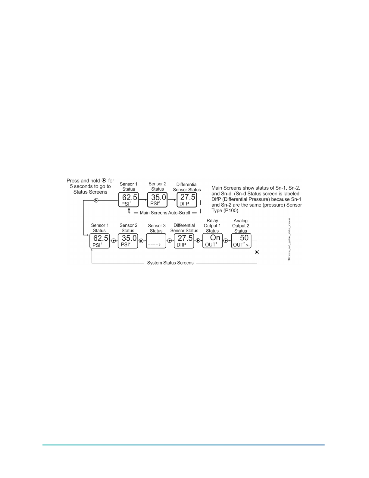
Viewing the System Status screens
From the Main screens, you can scroll through and view the System Status screens.
To view the system status screens, while the control module LCD is auto-scrolling through Main
screens, press Next (repeatedly) to scroll through and display the Sensor Status screens and the
Output Status screens for all sensors and outputs set up in your control system.
When you stop pressing Next, the Sensor or Output Status screen that is being viewed is displayed
for 2 minutes before it times out and reverts to the Main screens. The 2-minute pause allows you to
monitor a sensor that is changing quickly during system setup or normal system operation.
System 450 Main screens display the status at the hard-wired Sn-1, Sn-2, and Sn-3 sensors, and the
statuses of the functional sensor Sn-d when used in the control system. The System Status screens
also display hard-wired and functional sensor statuses along with output statuses.
Figure 21 shows the Main screens (sensor status) and the System Status screens (sensor and
output status) for a standard System 450 control system that is set up for differential pressure
control.
Figure 21: Main screens and system status screens example for a standard System 450
control system set up for differential control
Accessing the System Setup screens
From the Main screens, you can also access the Sensor Setup Start screen and the Output Setup
Start screens.
• From the Sensor Setup Start screen, you can set up all of the hard-wired sensors for your
control system. See Setting Up the Sensors and Transducers for procedures on setting up the
sensors and transducers.)
• From the Output Setup Start screens, you can set up each output in your control system. See
Setting up a Relay Output and Setting up an Analog Output for procedures on setting up
outputs.)
41System 450 Series Modular Control Systems with Standard Control Modules Technical Bulletin
Page 42
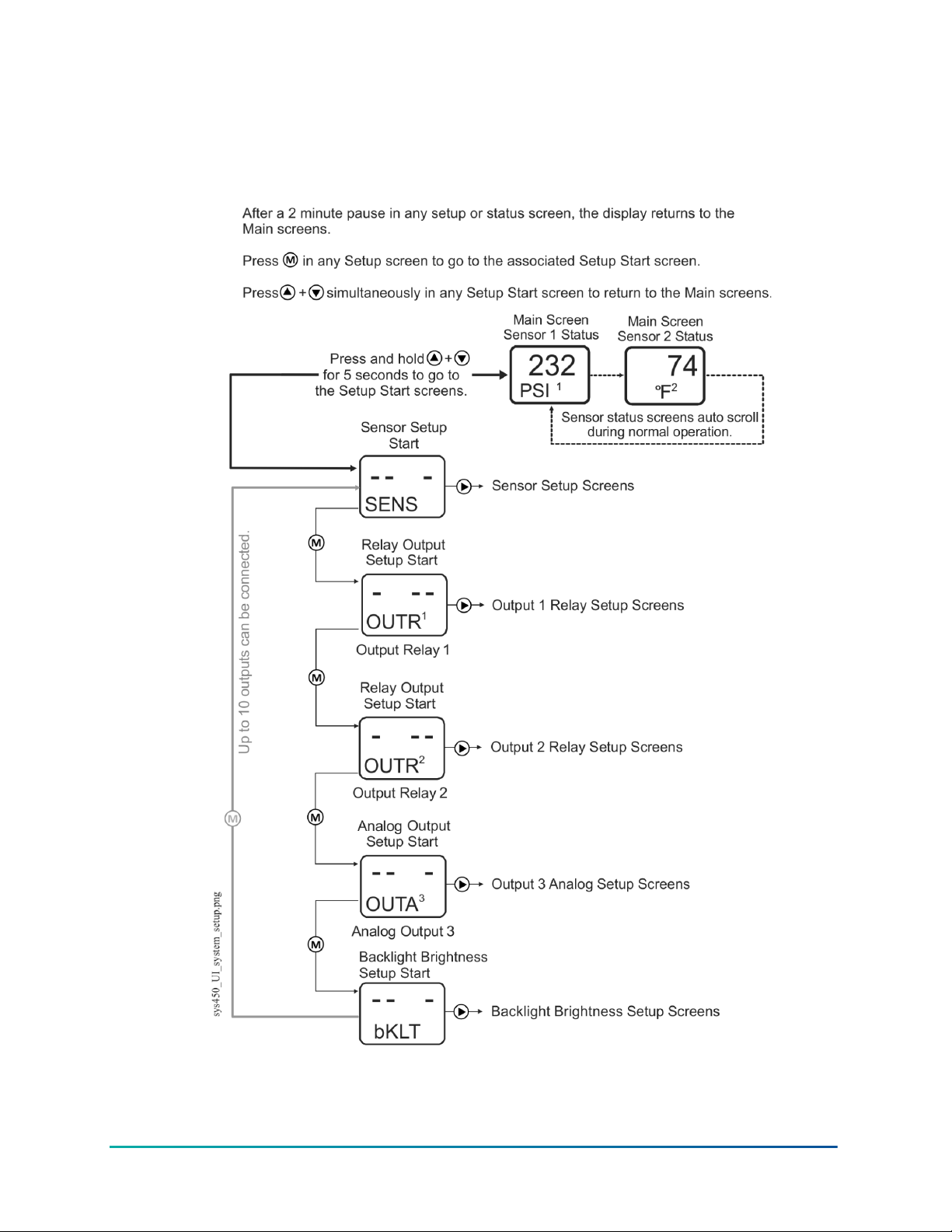
In this task you access and navigate the System 450 Setup Start screens.
1. In the Main screens, press Up and Down simultaneously and hold for five seconds. The
Sensor Setup Start (SENS) screen appears (Figure 22).
Figure 22: Accessing the Setup Start screens in the System 450 UI
2. Press M (repeatedly) to scroll through and access the Output Setup Start (OUTXx) screens for
all of the outputs in your control system.
System 450 Series Modular Control Systems with Standard Control Modules Technical Bulletin42
Page 43

Note: All Setup Start screens have four flashing dashes in the setup value fields. You
cannot enter values for the fields in the Setup Start screens.
3. Depending on the Setup Start screen that you have navigated to, press Next:
- in the Sensor Setup Start (SENS) screen to go the Select Sensor 1 Type (Sn-1) screen and
set up the sensors in your control system. See Setting Up the Sensors and Transducers for
procedures on setting up the hard-wired sensors and transducers.
- in any Output Setup Start (OUTXx) screen to go to the first output setup screen for the
output. (See Setting up a relay output or Setting up an analog output for the procedures
for setting up outputs.)
Note: You must set up the sensors and transducers in the System 450 UI before you can
set up the outputs in the UI.
In any of the system setup screens, press M to return to the setup start screen. In the setup start
screen, press Up and Down simultaneously or wait two minutes to return to the Main screens.
Setting up the sensors and transducers
To set up the sensors and transducers in your control system, you must select the correct Sensor
Type in the System 450 UI for each sensor and transducer used in your application. You can also
select an optional temperature offset value for any temperature sensor that is set up in your
control system.
Note: System 450 compatible sensors consist of temperature sensors, humidity sensors,
and pressure transducers. The term sensor refers to all System 450 compatible input devices
including transducers, unless noted otherwise.
The Sensor Type you select for a sensor or transducer automatically determines the condition type,
unit of measurement, minimum differential, setup value ranges, and default setup values for each
output in your control system that references the sensor.
System 450 control modules do the following:
• support specified temperature sensors, pressure transducers, and humidity sensors
• support binary inputs (a external set of dry contacts) connected to input sensor terminals (Sn1,
Sn2, or Sn3 and C)
• support configuration of Sn-1, Sn-2, and Sn-3 as any supported Sensor Type
• support the functional sensors HI-2 and HI-3 and the High Input Signal Selection feature
• support the functional sensor Sn-d and the Differential Control feature
• require Sn-1 and Sn-2 to be the same Sensor Type to set up the functional sensors HI-2 and Snd
• require Sn-1, Sn-2, and Sn-3 to be the same Sensor Type to set up the functional sensor HI-3 (in
addition to HI-2 and Sn-d)
Note: For a System 450 control system to operate properly, you must wire the correct sensor
or transducer model to the correct sensor input terminals on the control module, and select
the correct Sensor Type in the associated Select Sensor Type screen in the System 450 UI. See
Table 2 for System 450 Sensor Types and their associated values and settings.
See Table 14 through Table 23 in Repair and ordering information for more information on System
450 compatible sensors.
43System 450 Series Modular Control Systems with Standard Control Modules Technical Bulletin
Page 44
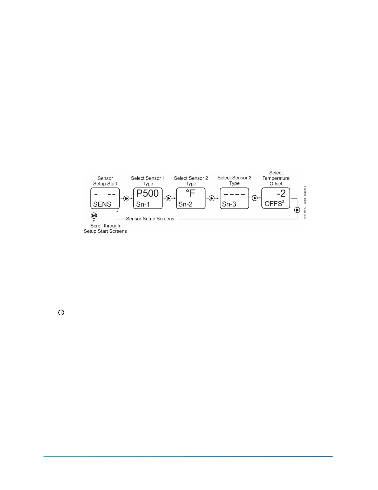
System 450 allows you to select an offset for each temperature sensor (only) in your control system.
Whenever you select the °F or °C Sensor Type for a sensor, a Select Temperature Offset screen
appears after the Select Sensor 3 Type screen for each temperature sensor in your control system.
The Select Temperature Offset screens are:
• Sensor Type °F, which enables an offset of up to +/- 5°F in 1-degree increments.
• Sensor Type °C, which enables an offset of up to +/- 2.5°C in 0.5-degree increments.
The temperature offset adjusts the displayed temperature value, sensed at the sensor, by the offset
value. For example, if the measured value is 72(°F) without an offset, and a -2(°F) offset is selected,
the measured value is offset -2(°F) and the displayed value is 70(°F).
In this task you set up the sensor’s Sensor Type and offsets for the temperature sensors as follows:
1. Access the System 450 UI and navigate to the Sensor Setup Start (SENS) screen (Figure 23).
2. In the Sensor Setup Start (SENS) screen, press Next to go to the next screen.
Figure 23: Sensor Setup Start, Select Sensor Type, and Select Temperature Offset screens
3. In the Select Sensor 1 Type (Sn-1) screen, press Up or Down to scroll through the Sensor
Types. When the desired Sensor Type is displayed (blinking), press Next to save the Sensor
Type selection and go to the Select Sensor 2 Type screen.
4. Repeat Step 3 in the Select Sensor 2 Type (Sn-2) screen and Select Sensor 3 Type (Sn-3)
screen if your control system uses a second or third sensor.
After you have selected the correct Sensor Type for each sensor in your control system,
the sensors are set up in the UI and can be selected and referenced by the outputs that
you set up in the system.
Note: System 450 standard control modules provide for three functional sensors. When
Sn-1 and Sn-2 are set up as the same Sensor Type, the High Input Signal Selection
functional sensor (HI-2) and Differential Control functional sensor (Sn-d) are enabled and
available in the Sensor Selection screens for each output. When Sn-1, Sn-2, and Sn-3 are
the same Sensor Type, the High Input Signal Selection functional sensor (HI-3) is also
enabled and available. See High Input Signal Selection and Differential Control for more
information on these functional sensors and the associated control features.
5. If a temperature Sensor Type (°F or °C) is selected for a sensor in your control system, a Select
Temperature Offset (OFFSx) screen is displayed after the Select Sensor 3 Type (Sn-3) screen
(for each temperature sensor in your control system). Select the desired temperature offset by
pressing Up or Down. Press Next to save the offset value and go to the next screen.
System 450 Series Modular Control Systems with Standard Control Modules Technical Bulletin44
Page 45
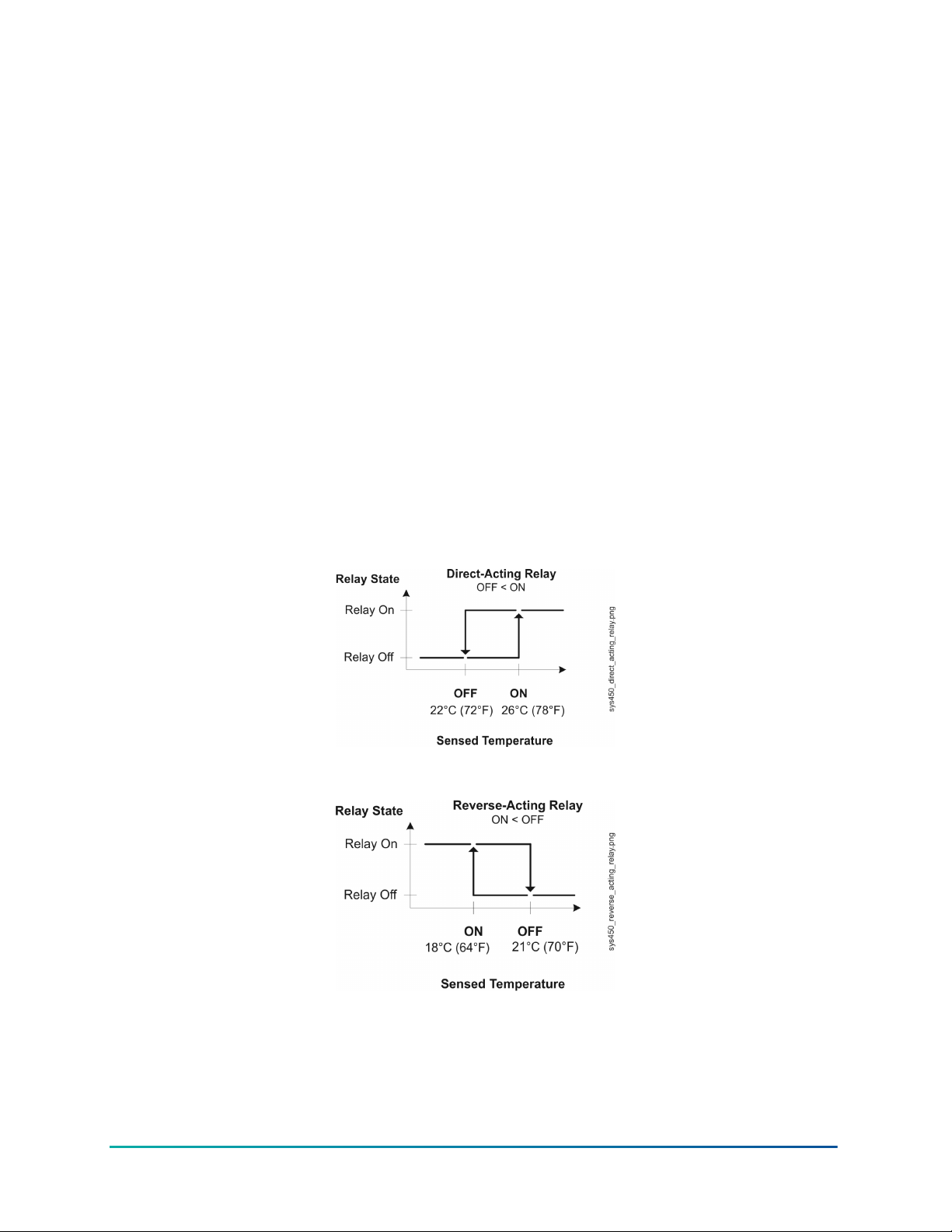
6. After all of the sensors and temperature offsets are set up:
- Press Next to return to the Sensor Setup Start (SENS) screen; then press M to scroll
through the output setup start screens and set up the outputs in your control system.
(See Setting up Control System Outputs for procedures on setting up outputs for your
control module.)
- Allow the UI to remain dormant for 2 minutes and the Main screen begins to autoscroll.
You may also return to the Main screen by pressing Up and Down simultaneously while a
Setup Start screen is displayed.
Setting up control system outputs
After setting up the sensors for your System 450 control system, you can reference the hard-wired
sensors and any functional sensors that resulted from the hard-wire sensor setup as you set up the
outputs.
Relay output setup
Relay Outputs provide single and multiple stage on/off control to controlled equipment. A Relay
Output can be set up to be a direct-acting relay or reverse-acting relay (Figure 24 and Figure 25).
See Relay Outputs for more information about System 450 Relay Output operation and the relay ON
and OFF states.
Figure 24: Direct-acting relay (OFF < ON) set up to control cooling
Figure 25: Reverse-acting relay (ON < OFF) set up to control heating
When you supply power to a module assembly, the control module polls all of the connected
modules, detects all of the outputs in the module assembly, then assigns an output number to each
output, and enables a Relay Output Setup Start (OUTRx) screen for each relay output detected
(Figure 26).
45System 450 Series Modular Control Systems with Standard Control Modules Technical Bulletin
Page 46
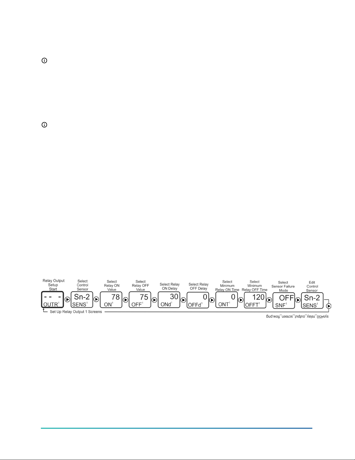
The first screen in the relay output setup menu flow is the Sensor Selection (SENSx) screen. The
sensor you select (Sn-1, Sn-2, Sn-3, HI-2, HI-3, or Sn-d) in this screen determines the Sensor Type
parameter ranges and values available in the remaining output setup screens.
Note: The condition (temperature, pressure, or humidity), unit of measurement, minimum
differential value, default setup values, and condition value ranges available in the output
setup screens are determined by the Sensor Type for the sensor that an output references. See
Table 5 for more information on sensors that are compatible with System 450 standard control
modules, their Sensor Types, and the values and ranges associated with each Sensor Type.
The Relay ON and Relay OFF parameters allow you to select the condition values at which the relay
turns on and turns off. The first time you access the Relay ON (ONx) and Relay OFF (OFFx) screens,
the default ON and OFF values for the referenced sensor appear.
Note: If you select a sensor (Sn-1, Sn-2, or Sn-3) that is set up as a binary input, the ON and
OFF selections screens do not appear in the Relay Output Setup screens. The relay ON and
OFF state is controlled by the binary input state. See Binary Input Control for Relay Outputs for
more information.
The minimum differential value for the condition is determined by the Sensor Type of the sensor
that an output references. The minimum differential is fixed and is automatically enforced in
the setup UI when you select ON and OFF values. After you select the ON value, the condition
values within the minimum differential range are not available to select. See Table 5 for minimum
differential ranges.
The ON Delay Time and OFF Delay Time parameters allow you to set a time (0 to 300 seconds) to
delay the relay from going On or Off after the ON or OFF value is reached. See Relay On and Off
Duration Control for more information.
The Minimum Relay ON Time and Minimum Relay OFF Time parameters allow you to set a
minimum time (0 to 300 seconds) that the relay stays On or Off after the ON or OFF value is
reached. See Relay On and Off Duration Control for more information.
The Sensor Failure Mode parameter allows you to select whether the output relay is on or off if
the referenced sensor encounters a sensor or wiring failure. See Sensor Failure Mode for more
information.
Figure 26: Relay output setup start screen and setup screen flow
Setting up a relay output
About this task: To set up a relay output, complete the following steps:
1. Access the System 450 UI and navigate to the desired Relay Output Setup Start (OUTRx)
screen (Figure 26). See Accessing and Navigating the User Interface.
2. In the Relay Output Setup Start (OUTRx) screen, press Next to go to the Select Sensor
(SENSx) screen. The Select Sensor screen does not appear here if a sensor is already selected
for this output. In that case, go to the next step. Press Up or Down to select the hard-wired or
functional sensor (Sn-1, Sn-2, Sn-3, Sn-d, HI-2, or HI-3) that the output references. Press Next
to save the sensor selection and go to the next screen.
System 450 Series Modular Control Systems with Standard Control Modules Technical Bulletin46
Page 47

3. In the Select Relay ON Value (ONx) screen, press Up or Down to select the temperature,
pressure, or humidity value at which the relay turns On. Press Next to save the ON value and
go to the next screen.
Note: If you selected the Sn-d sensor in Step 2, the Select Relay Differential ON Value
(dONx) screen is displayed. Press Up or Down to select the temperature, pressure, or
humidity differential value at which the relay turns On. Press Next to save the dON value
and go to next screen. See Differential Control for more information.
4. In the Select Relay OFF Value (OFFx) screen, press Up or Down to select the temperature,
pressure, or humidity value at which the relay turns Off. Press Next to save the OFF value and
go to the next screen.
Note: If you selected the Sn-d sensor in Step 2, the Select Relay Differential OFF Value
(dOFFx) screen is displayed. Press Up or Down to select the temperature, pressure, or
humidity differential value at which the relay turns OFF. Press Next to save the dOFF
value and go to the next screen. See Differential Control for more information.
5. In the Select ON Time Delay (ONdx) screen, press Up or Down to select the number of
seconds that the relay output delays going to the On state after the Relay ON (or dON) value
is reached. Press Next to save the ONd value and go to the next screen. See Relay On and Off
Duration Control for more information.
6. In the Select OFF Time Delay (OFFdx) screen, press Up or Down to select the number of
seconds that the relay output delays going to the OFF state after the Relay OFF (or dOFF)
value is reached. Press Next to save the OFFd value and go to the next screen. See Relay On
and Off Duration Control for more information.
7. In the Select Minimum Relay ON Time (ONTx) screen, press Up or Down to select the
minimum number of seconds that the relay remains On after the Relay goes ON. Press Next
to save the ONT value and go to the next screen. See Relay On and Off Duration Control for
more information.
8. In the Select Minimum Relay OFF Time (OFFTx) screen, press Up or Down to select the
minimum number of seconds that the relay remains Off after the Relay goes OFF. Press Next
to save the OFFT value and go to the next screen. See Relay On and Off Duration Control for
more information.
9. In the Select Sensor Failure Mode (SNFx) screen, press Up or Down to select whether the
output relay stays on or off when a sensor failure is detected. Press Next to save the Sensor
Failure Mode value and go to the next screen.
10. In the Edit Sensor (SENSx) screen, if the displayed sensor (Sn-1, Sn-2, Sn-3, Sn-d, HI-2, or HI-3)
is the correct sensor for the output relay, the output setup is complete. Press Next to return
to the Relay Output Setup Start screen.
11. In the Edit Sensor (SENSx) screen, if the displayed sensor (Sn-1, Sn-2, Sn-3, Sn-d, HI-2, or HI-3)
is not the correct sensor for the output relay, press Up or Down to select the correct sensor.
Press Next to save the new sensor selection and go to the Relay Output Setup Start screen.
Press Next again to go to the Relay ON Value screen and repeat Step 3 through Step 10 for
the new sensor.
Result The relay output is set up and saved in the control module. If you need to set up the next
output, press M to navigate to the next Output Setup Start screen. If you have completed your
control system setup, press Up and Down simultaneously or wait two minutes to return to the Main
screens.
47System 450 Series Modular Control Systems with Standard Control Modules Technical Bulletin
Page 48
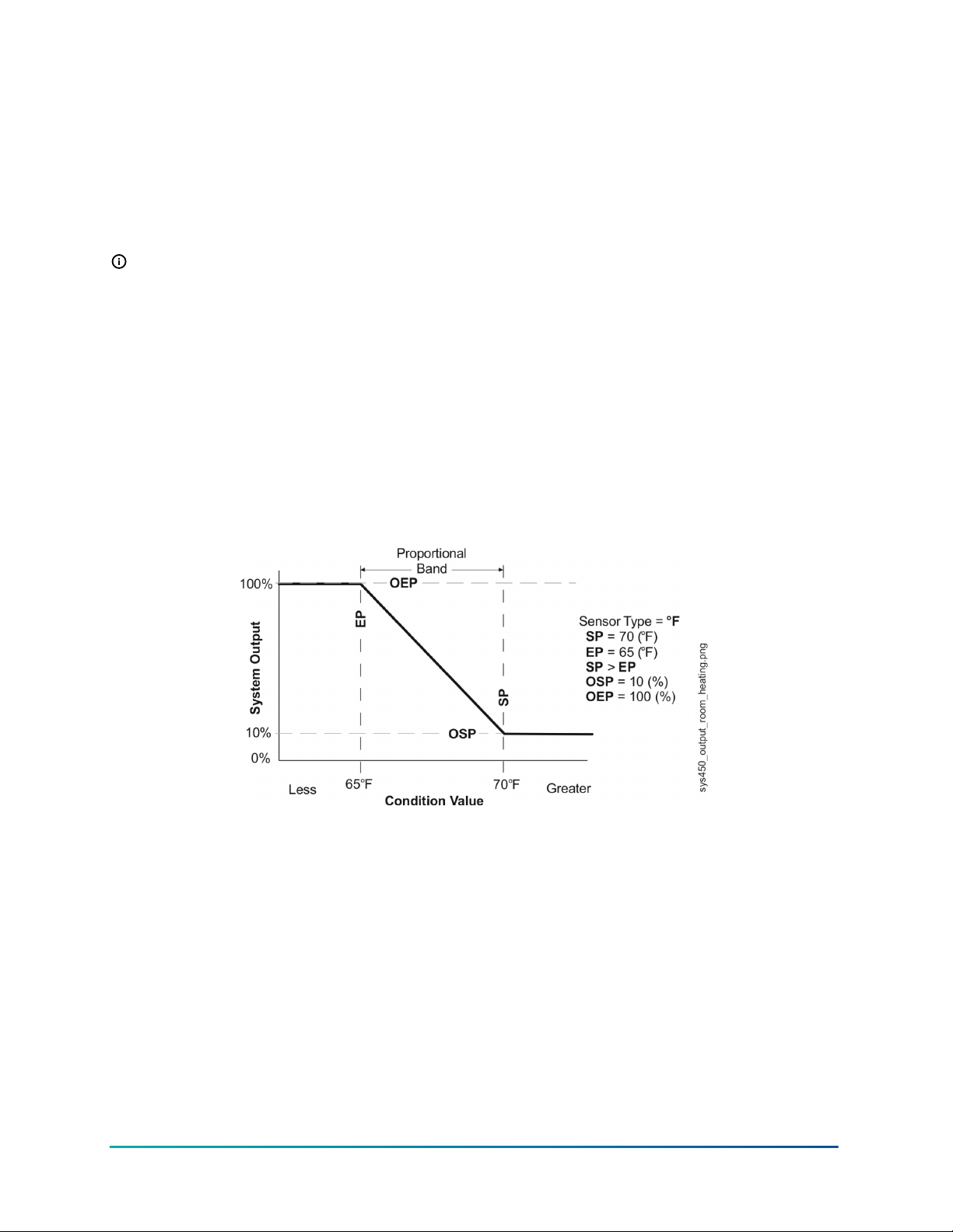
Analog output setup
Analog Outputs provide proportional analog control signals to controlled equipment based on the
sensed conditions. See Analog Outputs for more information.
When you supply power to a module assembly, the control module polls all of the connected
modules, detects all of the outputs in the module assembly, then assigns an output number to
each output, and enables an Analog Output Setup Start (OUTAx) screen for each analog output
detected (Figure 29). See Analog Outputs for more information.
Note: The condition (temperature, pressure, or humidity), unit of measurement, minimum
differential value, default setup values, and condition value ranges available in the output
setup screens are determined by the Sensor Type of the sensor that you select for the output.
See Table 5 for more information on sensors that are compatible with System 450 standard
control modules, their Sensor Types, and the values and ranges associated with each Sensor
Type.
The Setpoint (SP) and End Point (EP) parameters allow you to set up a proportional band (or
throttling range) for the control loops in your controlled system.
The Output at Setpoint (OSP) and Output at End Point (OEP) parameters allow you to select the
output signal strength (as a percentage of the total signal strength range) that an analog output
sends to the controlled equipment at Setpoint and End Point.
Figure 27: Relationship between setpoint, end point, output at setpoint, and output at end
point for an Analog Output that controls room heating
System 450 Series Modular Control Systems with Standard Control Modules Technical Bulletin48
Page 49
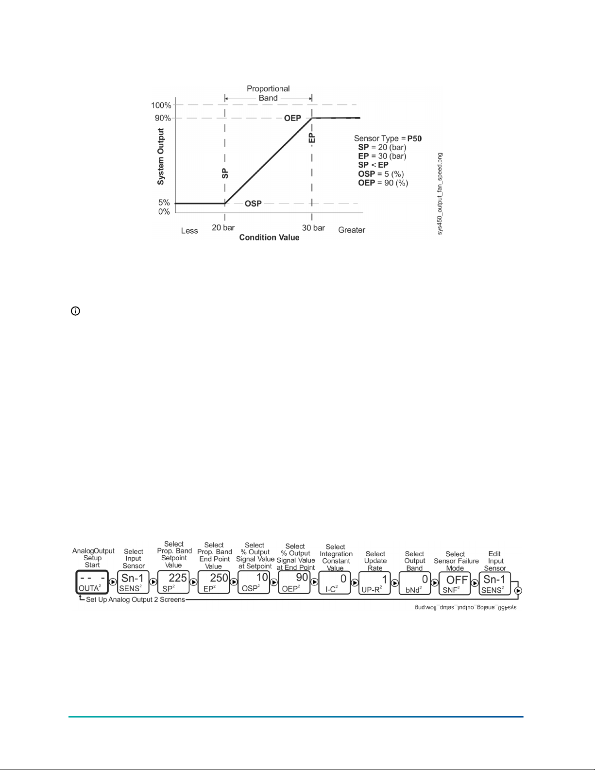
Figure 28: Relationship between Setpoint, End Point, Output at Setpoint, and Output at End
Point for an Analog Output That Controls Condenser Fan Speed
The relationship between these four setup values (SP, EP, OSP, and OEP) determines the analog
output’s proportional control action, which is indicated on the control module LCD by the control
ramp indicator. See Figure 1 and Direct and Reverse Control Actions for Analog Outputs for more
information on the control ramp indicator.
Note: System 450 analog outputs that reference the differential control sensor (Sn-d) use a
Differential Setpoint (dSP) and Differential End Point (dEP) to define the output’s proportional
band. See Differential Control for more information.
The Integration Constant (I-C) parameter allows you to select an integration constant for the
analog signal. Selecting an integration constant other than 0 enables proportional plus integral
control action, which in many applications can drive the condition closer to setpoint (than
proportional-only control action). See Proportional Plus Integral Control and Integration Constants
for more information. See Determining the Integration Constant for an Analog Output for
procedures on determining and testing the integration constants in your control application.
The Output Signal Update Rate screen and the Output Signal Deadband screen allow you to reduce
the rate at which an analog output updates the output signal strength, reducing wear on controlled
equipment such as actuators. See Analog Output Update Limiters and Analog Output Deadband for
more information.
The Sensor Failure Mode (SNF) parameter allows you to select whether the analog output signal
is off, corresponding to the lowest output capacity, or on, corresponding to the highest output
capacity when a sensor failure is detected. See Sensor Failure Mode for more information.
Figure 29: Analog Output setup start screen and setup screens flow
Setting up an analog output
About this task:
In any of the system setup screens, press M to return to the setup start screen. In the setup start
screen, press Up and Down simultaneously or wait two minutes to return to the Main screens. In
this task you set up an analog output.
49System 450 Series Modular Control Systems with Standard Control Modules Technical Bulletin
Page 50

1. Access the System 450 UI and navigate to the desired Analog Output Setup Start (OUTAx)
screen (Figure 29). See Accessing and Navigating the User Interface for information on
accessing the System Setup screens.
2. In the Analog Output Setup Start (OUTAx) screen, press Next to go to the Select Sensor
(SENsx) screen. The Select Sensor screen does not appear here if the sensor is already
selected for this output. In that case, go to the next step. Press Up or Down to select
the hard-wired or functional sensor (Sn-1, Sn-2, Sn-3, Sn-d, HI-2, or HI-3) that the output
references. Press Next to save the sensor selection and go to the Select Setpoint Value
screen.
3. In the Select Setpoint Value (SPx) screen, press Up or Down to select the Setpoint value. The
controlled system drives towards Setpoint [SP] and away from End Point [EP], which together
define the proportional band for the analog output. Press Next to save the Setpoint value
and go to the next screen.
Note: If you selected the Sn-d sensor in Step 2, the Select Differential Setpoint Value
(dSPx) screen is displayed. Press Up or Down to select the temperature, pressure, or
humidity differential value towards which the controlled system is driving. Press Next to
save the dSP value and go to the Select Differential End Point Value (dEPx) screen. See
Differential Control for more information.
4. In the Select End Point Value (EPx) screen, press Up or Down to select the End Point value.
The controlled system operates between Setpoint and End Point, which together define the
proportional band for the analog output. Press Next to save the End Point value and go to
the next screen.
Note: If you selected the Sn-d sensor in Step 2, the Select Differential End Point Value
(dEPx) screen is displayed, press Up or Down to select the differential End Point value.
The controlled system operates between differential Setpoint and differential End Point,
which together define the proportional band for the analog output. Press Next to save
the dEP value and go to the next screen. See Differential Control for more information.
5. In the Select Output Signal Strength at Setpoint (OSPx) screen, press Up or Down to select
the value in percent of the output signal strength (0 to 100%), corresponding to the lowest
output capacity, when the sensor is at Setpoint (SPx). Press Next to save the displayed OSP
value and go to the next screen.
6. In the Select Output Signal Strength at End Point (OEPx) screen, press Up or Down to
select the value in percent of the output signal strength (0 to 100%), corresponding to the
highest output capacity, when the sensor is at the End Point (EPx). Press Next to save the
displayed OEP value and go to the next screen.
7. In the Select Integration Constant (I-Cx) screen, press Up or Down to select the integration
constant value for the analog output. See Determining the Integration Constant for an
Analog Output for more information. Press Next to save the displayed I-C value and go to the
next screen.
8. In the Select Output Signal Update Rate (UP-Rx) screen, press Up or Down to select the
output update rate value. One (second) is the default value. You can select a value between
1 and 240 seconds. See Analog Output Update Limiters for more information. Press Next to
save the output update rate value and go to the next screen.
System 450 Series Modular Control Systems with Standard Control Modules Technical Bulletin50
Page 51
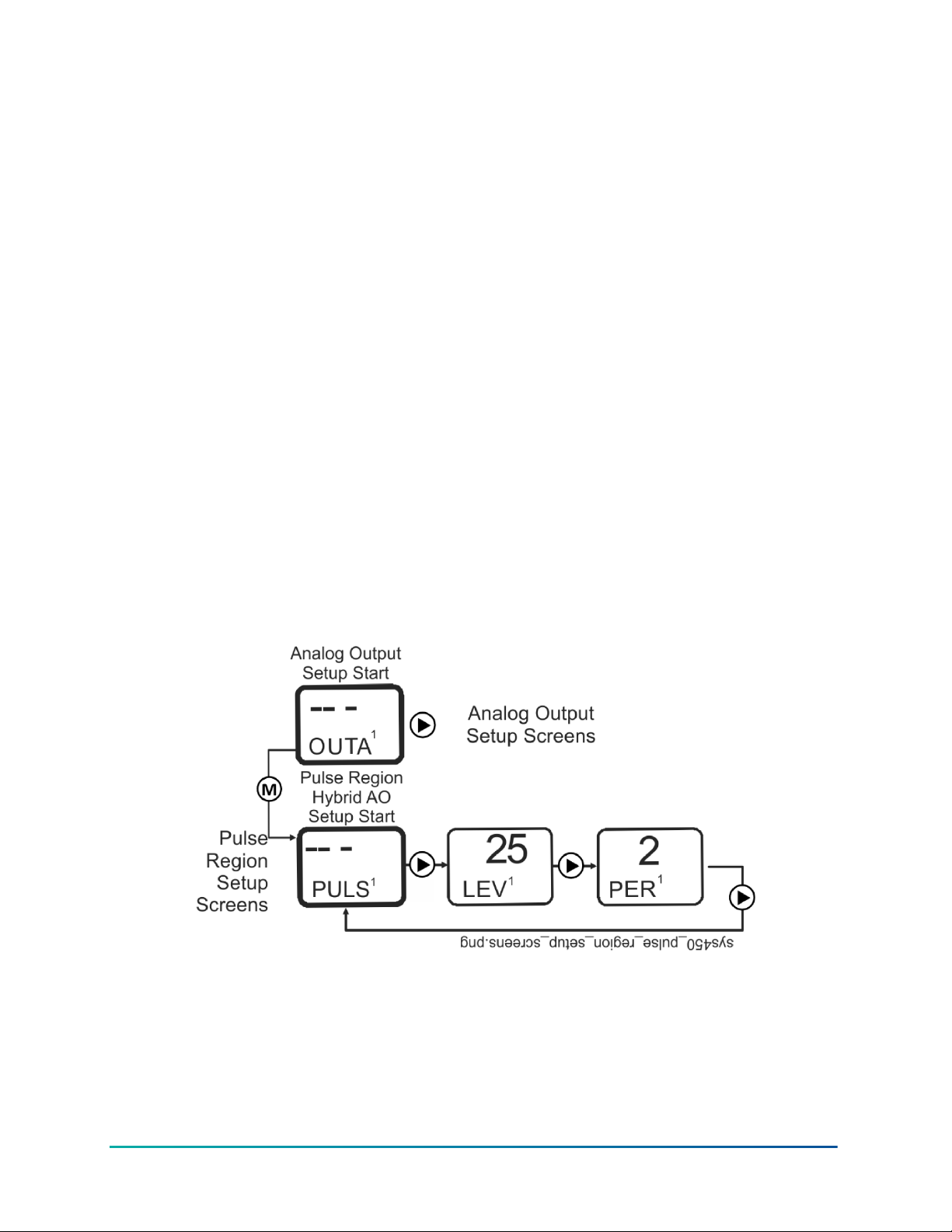
9. In the Select Output Signal Deadband (bNdx) screen, press Up or Down to select the output
deadband value as a percentage of the total output signal range. Zero (percent) is the default
value. You can select a value between 0 and 50 (percent). See Analog Output Deadband for
more information. Press Next to save the output deadband value and go to the next screen.
10. In the Select Sensor Failure Mode (SNFx) screen, press Up or Down to select whether the
analog output signal is to be set to its ON or OFF value when a failure of the referenced
sensor is detected. When sensor that is referenced by analog output fails, the ON value sets
the output to the OEP value and the OFF value sets the output to the OSP value. Press Next to
save the displayed SNF value and go to the next screen.
11. In the Edit Sensor (SENSx) screen, you can change the hard-wired or functional sensor that
the output currently references.
a. If the displayed sensor (Sn-1, Sn-2, Sn-3, Sn-d, HI-2, or HI-3) is the correct sensor for the
output relay, the output setup is complete. Press Next to go to the Analog Output Setup
Start screen.
b. If the displayed sensor (Sn-1, Sn-2, Sn-3, Sn-d, HI-2, or HI-3) is not the correct sensor for
the output relay, press Up or Down to select the correct sensor. Press Next to save the
new sensor selection and go to the Analog Setpoint Value screen. Repeat Step 3 through
Step 10 for the new sensor.
12. When you complete setting up the analog output, press M to return to the Analog Output
Setup Start (OUTAx) screen.
Result The analog output is set up and saved in the control module.
Pulse region hybrid analog output setup
Figure 30: Pulse region hybrid AO setup start screen
Setting up a pulse region hybrid analog output
About this task:
In this task you set up the Pulse Region of a hybrid analog output for Output 1 on a C450CPW-400
control module.
51System 450 Series Modular Control Systems with Standard Control Modules Technical Bulletin
Page 52
1. From the Pulse Region Hybrid AO Setup Start Screen (PULSx) for Analog Output 1, press
Next to go to the output’s Pulse Output Level Selection Screen (LEVx).
Note: Only Analog Output 1 (OUTA1) is capable of generating the Pulse-AO. Additional
AO expansion modules provide a standard 0 to 10 VDC or 4 to 20 mA output signal.
2. In the Pulse Output Level Selection Screen (LEVx), set the Pulse Output Level to a (percent)
value that is higher than required for the EC Motor to rotate. If the motor requires a
minimum speed reference of 2 VDC before it rotates, set the Pulse Level higher than 2.5 VDC
(25%). Press Up or Down to select this Output’s Pulse Output Level value. Press Next to save
the Pulse Output Level value and go to the Pulse Period Selection Screen (PERx).
Note: Screen example shows the Pulse Output Level set to 25%. Range is 0 to 100%. Set
the Pulse Output Level to 0% to disable the pulse output. Set the Pulse Output Level to
100% to use the pulse output over the entire 0 to 10 V output range.
3. In the Pulse Period Selection Screen (PERx), press Up or Down to select this output’s Pulse
Period value. Press Next to save your Pulse Period value selection and go to the Pulse
Region Hybrid AO Setup Start Screen (PULSx).
Result Screen example shows the Pulse Period set for 2 seconds. Range is 1 to 30 seconds.
Setting up outputs that reference a P 110 sensor
The P 110 Sensor Type can monitor negative pressure down to 20 inHg (-10 psi). When referencing
a P 110 sensor, System 450 displays negative pressure values in inHg on the Main and System
Status screens. But when you set up an output that references a P 110 sensor and the setup value is
a negative pressure value, you must select the pressure value in negative psi (not inHg).
Use Table 8 to determine the negative PSI setup value that corresponds to your inHg target value.
For example, if you want a relay output to go off when the sensed pressure reaches 7 inHg, you
select the value -3.5 (psi) in the output’s Relay OFF Selection screen.
Table 8: inHg target values and equivalent psi setup values
inHg value psi setup value inHg value psi setup value
1 -0.5 11 -5.5
2 -1.0 12 -6.0
3 -1.5 13 -6.5
4 -2.0 14 -7.0
5 -2.5 15 -7.5
6 -3.0 16 -8.0
7 -3.5 17 -8.5
8 -4.0 18 -9.0
9 -4.5 19 -9.5
10 -5.0 20 -10.0
When an output is set up for Differential Control and references the P 110 Sensor Type (Sn-1 and
Sn-2 are both P 110 Sensor Type), the sensed negative pressure values displayed in the Main screen
for differential pressure status (dIFP) are displayed as negative psi values, not inHg values.
System 450 Series Modular Control Systems with Standard Control Modules Technical Bulletin52
Page 53

Determining the integration constant for an analog output
The default Integration Constant (I-C) setting for analog outputs is 0 (zero) or no integration
constant. An I-C setting of 0 provides a proportional-only analog signal. Most applications do not
require you to change this default setting. See Proportional Plus Integral Control and Integration
Constants for more information.
If you want to apply proportional plus integral to a control loop in your controlled system, here are
two methods of determining the best I-C setting for the analog output that controls the loop.
Note: Both of the following methods for determining an I-C setting require you to install,
set up, and operate the control loop in your controlled system under a variety of typical load
conditions and observe the response to load changes and different I-C settings.
Testing the slowest to fastest time integral to determine I-C setting
One method of determining the best I-C setting for a control loop is to observe the controlled
system’s operation at the slowest time integral (I-C setting of 1) and then increase the I-C setting
one step at a time to determine the best setting.
In this task you determine the best I-C setting for an analog output by testing slowest to fastest
time integral.
1. Set up the System 450 control loop for proportional-only control (I-C setting of 0 [zero]), power
the controlled system under typical or steady load conditions, and allow the system to stabilize
at a control point somewhere in the proportional band between the Setpoint and End Point
values.
2. After the controlled system has stabilized at a control point, set the integration constant to the
slowest time integral (I-C setting of 1) and observe the control point to see if it stabilizes closer
to the selected Setpoint.
- If the control point overshoots Setpoint, go to Step 3.
- If the control point stabilizes closer to Setpoint but does not overshoot Setpoint, set the
integration constant to the next (faster) time integral and then observe the control point
to see if it stabilizes closer to the selected Setpoint.
- If the control point does not overshoot Setpoint at new I-C setting, continue to
increase the setting and observe the system until the control point overshoots
Setpoint, then go to Step 3.
3. When the control point overshoots Setpoint, continue to observe the control point:
- If the control point drifts past Setpoint, reverses, and then drifts back towards Setpoint
and stabilizes at or near Setpoint, go to Step 4.
- If the control point drives significantly beyond Setpoints, then reverses quickly, drives
back past Setpoint, and continues oscillating significantly above and below Setpoint, reset
the I-C setting to the previous (slower) time integral and go to Step 4.
53System 450 Series Modular Control Systems with Standard Control Modules Technical Bulletin
Page 54

4. When the control point stabilizes near Setpoint or drifts slightly above and below Setpoint,
operate the control loop under a variety of load conditions, including the maximum load
condition:
- If the control point drives past Setpoint and begins to oscillate significantly above and
below Setpoint, reset the I-C setting to the previous (slower) time integral and repeat Step
3.
- If the control point drifts to or past Setpoint and stabilizes near Setpoint, the current I-C
setting for your control loop is correct.
Continue to observe the controlled system until you are sure that the system control point stabilizes
somewhere near Setpoint and does not oscillate under all load conditions.
Using the response time to a step change to determine the IC Setting
About this task:
Another method for determining the best I-C setting for a System 450 control loop is to temporarily
create a step change that shifts the proportional band in your controlled system away from the
original or desired proportional band. To do so, measure the (first response) time it takes for your
controlled system to drive to and stabilize at the shifted control point. Then shift (step change) the
proportional band back to original and measure the (second response) time that it takes to return
to the original control point.
You need a digital voltmeter set to VDC to perform this procedure.
In this task you determine the best I-C setting for a control loop using the response time to a step
change.
1. Set up the System 450 analog output for proportional-only control (I-C setting of 0 [zero]),
power your controlled system on, operate the system under steady load conditions, and
allow the control loop to stabilize at a control point within the proportional band between the
selected Setpoint and End Point values.
2. Connect a digital volt-meter across the analog output terminals to measure VDC signal
strength changes. Measure and record the signal strength voltage at this (original) stable
control point.
3. Change the Setpoint and End Point values to shift (step change) the proportional band 25%
away from the original proportional band; the VDC signal rises (or drops) immediately and
significantly in response to the proportional band shift. Begin timing the response (to the first
step change) at this voltage rise (or drop). The direction of the voltage changes (rise or drop)
depends on whether the analog output is set up as adirect-acting or reverse-acting output
signal. These instructions refer to the room heating application example shown in Figure 31.
System 450 Series Modular Control Systems with Standard Control Modules Technical Bulletin54
Page 55
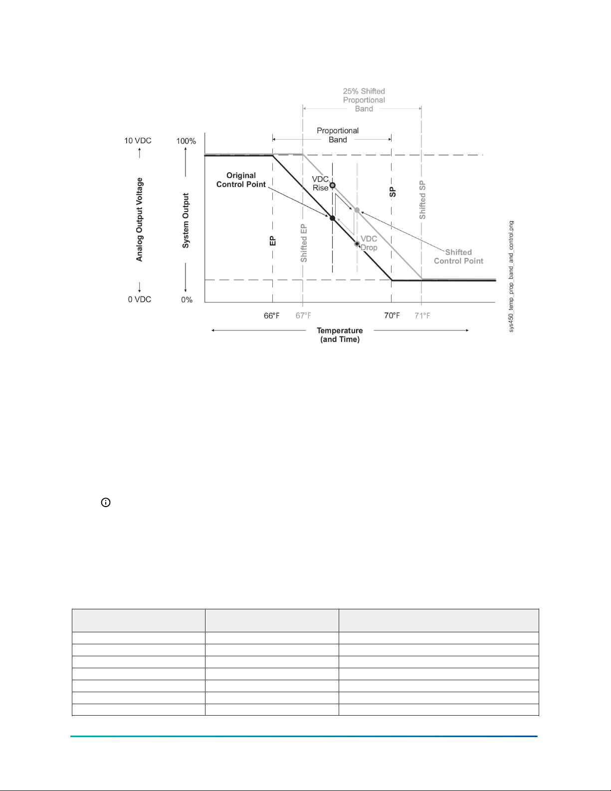
Figure 31: Graph showing temporary proportional band and control point shifts used to measure
response time in a heating application
4. Observe the system response and record the time it takes for the measured voltage to
drive to and stabilize at the shifted control point in the shifted proportional band. Typically,
the shifted control point voltage is slightly higher [or lower] than the original control point
voltage.
5. With the controlled system stabilized at the shifted control point, return (second step change)
the Setpoint and End Point values back to the original proportional band. The signal VDC
drops (or rises) immediately and significantly in response to the proportional band shift back
to original. Begin timing the response (to the second step change) at this voltage drop (or
rise).
6. Observe the system response and record the time it takes for the measured voltage to drive
back to and stabilize at original control point (voltage) in the original proportional band.
Note: In many applications, the response time away from the original control point
to the shifted control point is different from the response time of the shifted control
point back to the original control point, depending on a variety of factors such as system
load and system output. Choose the slower of the two measured response times to
determine the I-C setting for your application.
7. Use the slower of the two measured response times and the following table to determine
which integration constant (I-C setting) to set on the control and test first.
Table 9: Response times, reset rates, and integration constants
Slowest measured response time
for control point shift
N/A 0 No reset rate
10 to 15 minutes 1 1 hour (3,600 seconds)
6 to 10 minutes 2 30 minutes (1,800 seconds)
3 to 6 minutes 3 15 minutes (900 seconds)
1 to 3 minutes 4 5 minutes (300 seconds)
30 to 60 seconds 5 2 minutes (120 seconds)
10 to 30 seconds 6 1 minute (60 seconds)
Select this integration constant
(I-C) value for the analog output
Estimated total reset rate for integration
constant
55System 450 Series Modular Control Systems with Standard Control Modules Technical Bulletin
Page 56
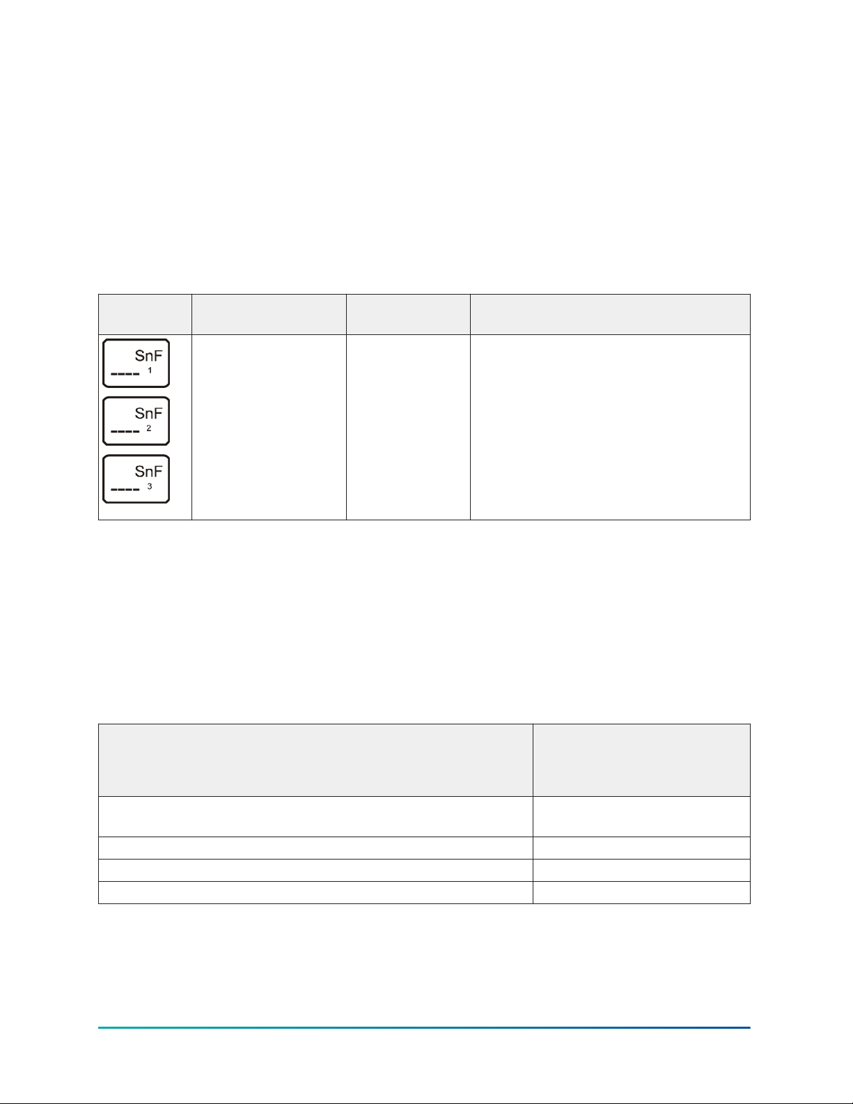
8. Set the integration constant to the determined I-C setting. Operate and observe the
controlled system at a variety of load conditions to determine if the system is stable at the
determined I-C setting over the entire output range of the controlled system.
Troubleshooting System 450 control systems
System 450 control modules display error messages on the LCD when the module detects a sensor,
sensor wiring, sensor power, or power supply failure.
Table 10 shows the System 450 error messages that may be displayed, and provides possible causes
for the error messages and the solutions for remedying the errors.
Table 10: System 450 control system LCD error messages
Error screen Problem or
symptom
Sensor failure is
detected and < SNF >
is displayed (instead
of a value).
Outputs that
reference the failed
sensor are operating
in the Sensor Failure
Modes selected for
the Output at setup.
Possible cause Solution
Sensor, sensor
wiring, or sensor
connections may
have failed to
open or close.
Check and verify the integrity of sensor
wiring and connections. Measure the
voltage between the sensor terminal
(Sn1, Sn2, or Sn3) and the low-voltage
common (C) terminal (with the sensor
connected). See Table 11 for the sensor’s
expected voltage range. If the sensor
wiring and sensor connections are good,
replace the sensor and recheck the
voltage.
Specified voltage ranges for sensors
Table 11 provides the specified operating voltage range for System 450 sensors. To determine if
a sensor is operating in the specified range, measure the voltage between the sensor’s terminal
connections at the System 450 control module (the Sn1, Sn2, or Sn3 terminal and one of the C
terminals).
If the voltage is out of the specified range, check the sensor wiring for shorted or open circuits.
Repair or replace wiring as needed. If the wiring appears to be in good condition, replace the
sensor and retest the voltage and operation.
Table 11: Specified voltage ranges between sensor terminals
Connected sensor Specified voltage range
A99B Series and TE-6xxx Series Nickel (1,000 ohms at 70°F)
Temperature Sensors
HE-69xx Humidity Sensor 0 VDC to 5.0 VDC
DPT2650 Low-Pressure Differential Sensor 0 VDC to 5.0 VDC
P599 Series Pressure Transducer 0.5 VDC to 4.5 VDC
System 450 Series Modular Control Systems with Standard Control Modules Technical Bulletin56
Measured between a sensor
terminal (Sn1, Sn2, or Sn3)
and a common terminal (C)
0.49 VDC to 1.43 VDC
Page 57
Repair and ordering information
Table 12 provides ordering information for the System 450 Series modules that can be used to build
standard control systems. See System 450 Series Modular Control Systems with Standard Control
modules technical specifications for detailed product specifications for the control modules listed
in Table 12. Table 14 through Table 23 provide ordering information for the System 450 compatible
sensors and transducers. For more information on installing System 450 compatible sensors and
transducers, see Related documentation for additional information on the modules listed in Table
12.
Table 12: System 450 modules and accessories ordering information
Product code Description
C450CBN-4C Standard Control Module with LCD, Four-Button Touchpad UI, and Relay Output; provides one relay
output (SPDT line-voltage relay) for SPDT control.
C450CCN-4C Standard Control Module with LCD, Four-Button Touchpad UI, and Relay Output; provides two relay
outputs (SPDT line-voltage relays) for SPDT control.
C450CCU-4C Condensing unit control module with LCD, four-button Touchpad, UI, and two SPDT line-voltage relay
outputs. Includes two A99BB-500C temperature sensors with 5 m or 16.38 ft cable length. Sensor
temperature range: -40°C to 120°C (-40°F to 250°F); Cable jacket temperature range: -40°C to 100°C
(-40°F to 212°F)
C450CPN-4C Standard Control Module with LCD, Four-Button Touchpad UI, and Analog Output; provides one
analog output (0–10 VDC or 4–20 mA self-selecting signal) for proportional control.
C450CQN-4C Standard Control Module with LCD and Four-Button Touchpad UI, and Analog Output; provides two
analog outputs (0–10 VDC or 4–20 mA self-selecting signals) for proportional control.
C450CPW-400C Hybrid Analog Output Control Module with LCD, Four-Button Touchpad UI, Hybrid Analog Output and
Optional High Input Signal Select; provides one hybrid analog output and optional high input signal
select primarily used for variable-speed EC motor speed control.
Only Analog Output 1 (OUTA1) can be configured as a hybrid analog output and/or use the High
Input Signal Selection feature. These features are not available for any of the other outputs in a
System 450 control system that uses the C450CPW-400C as the control module.
C450SBN-4C Relay Output Expansion Module; provides one SPDT line-voltage relay output.
C450SCN-4C Relay Output Expansion Module; provides two SPDT line-voltage relay outputs.
C450SPN-4C Analog Output Expansion Module; provides one analog output (0–10 VDC or 4–20 mA self-selecting
signal) for proportional control.
C450SQN-4C Analog Output Expansion Module; provides two analog outputs (0–10 VDC or 4–20 mA self-selecting
signals) for proportional control.
C450YNN-1C Power Module; provides 24 V to System 450 Module Assembly; 120 VAC or 240 VAC supply power
input terminals.
Table 13: System 450 mounting accessories
Product code Description
BKT287-1R DIN Rail; 0.30 m (12 in.) long
BKT287-2R DIN Rail; 1 m (39.3 in.) long
BKT287-3R DIN Rail; 0.61 m (24 in.) long
BKT287-4R DIN Rail; 0.36 m (14 in.) long
PLT344-1R DIN Rail End Clamps (2 clamps)
WHA-C450-100C System 450 module connection extension cable, 100 cm (3.3 ft) long
57System 450 Series Modular Control Systems with Standard Control Modules Technical Bulletin
Page 58
Table 14: System 450 compatible A99B temperature sensors and accessories ordering
information
Product code Description
A99BA-200C PTC Silicon Sensor with Shielded Cable; Cable Length 2 m (6.5 ft);
A99BB-25C PTC Silicon Sensor with PVC Cable; Cable Length 0.25 m (9.75 in.);
A99BB-200C PTC Silicon Sensor with PVC Cable; Cable Length 2 m (6.5 ft);
A99BB-300C PTC Silicon Sensor with PVC Cable; Cable Length 3 m (9.75 ft);
A99BB-500C PTC Silicon Sensor with PVC Cable; Cable Length 5 m (16.38 ft);
A99BB-600C PTC Silicon Sensor with PVC Cable; Cable Length 6 m (19.5 ft);
A99BC-25C PTC Silicon Sensor with High Temperature Silicon Cable; Cable Length 0.25 m (9.75 in.)Sensor
A99BC-300C PTC Silicon Sensor with High Temperature Silicon Cable; Cable Length 3 m (9.75 ft)Sensor
A99BC-1500C PTC Silicon Sensor with High Temperature Silicon Cable; Cable Length 15 m (49 ft)Sensor Temperature
BOX10A-600R PVC Enclosure for A99 Sensor; Includes Wire Nuts and Conduit Connector (for Outdoor Sensor)
WEL11A-601R Immersion Well for A99 Sensor Liquid Sensing Applications
A99-CLP-1 Mounting Clip for A99 Temperature Sensor
ADP11A-600R Conduit Adaptor, 0.5 in. Snap-Fit EMT Conduit Adaptor (box of 10)
TE-6001-1 Duct Mounting Hardware with Handy Box for A99 Sensor
TE-6001-11 Duct Mounting Hardware without Handy Box for A99 Sensor
SHL10A-603R Sun Shield (for Use with Outside A99 Sensors in Sunny Locations)
Sensor Temperature Range: -40 to 120°C (-40 to 250°F)
Cable Jacket Temperature Range: -40 to 100°C (-40 to 212°F)
Sensor Temperature Range: -40 to 120°C (-40 to 250°F)
Cable Jacket Temperature Range: -40 to 100°C (-40 to 212°F)
Sensor Temperature Range: -40 to 120°C (-40 to 250°F)
Cable Jacket Temperature Range: -40 to 100°C (-40 to 212°F)
Sensor Temperature Range: -40 to 120°C (-40 to 250°F)
Cable Jacket Temperature Range: -40 to 100°C (-40 to 212°F)
Sensor Temperature Range: -40 to 120°C (-40 to 250°F)
Cable Jacket Temperature Range: -40 to 100°C (-40 to 212°F)
Sensor Temperature Range: -40 to 120°C (-40 to 250°F)
Cable Jacket Temperature Range: -40 to 100°C (-40 to 212°F)
Temperature Range: -40 to 120°C (-40 to 250°F)
Cable Jacket Rated for Full Sensor Temperature Range.
Temperature Range: -40 to 120°C (-40 to 250°F)
Cable Jacket Rated for Full Sensor Temperature Range.
Range: -40 to 120°C (-40 to 250°F)
Cable Jacket Rated for Full Sensor Temperature Range.
Note: Refer to the A99B Series Temperature Sensors Product/Technical Bulletin (LIT-125186) for
more information.
Table 15: System 450 compatible TE-6000 Series 1,000 Ohms Nickel temperature sensors and
accessories ordering information
Product code Description
TE-6000-1,
TE-6000-1x,
TE-6000-6
TE6000 Series 1,000 ohms at 21°C (70°F) nickel temperature sensors (only). Only the TE-6000-6 sensor
can be used for the entire HI ° C and HI ° F temperature range. Different sensing element packages
are available for various applications. For a complete list of compatible 1,000 ohms nickel sensors,
including sensor descriptions, technical specifications, and mounting accessories, refer to the TE-6000
Series Temperature Sensing Elements Product Bulletin (LIT-216288). (System 450 Sensor Types HI°C and HI
°F.)
Table 16: System 450 compatible TE-6300 Series 1,000 Ohms Nickel temperature sensors and
accessories ordering information
Product code Description
TE-631x-x TE6300 Series 1,000 ohms nickel averaging and 1,000 ohms thin-film nickel temperature sensors
(only). For a complete list of compatible 1,000 ohms nickel averaging and thin-film nickel sensors,
including sensor descriptions, technical specifications, and accessories, refer to the TE-6300 Series
Temperature Sensors Product Bulletin (LIT-216320). (System 450 Sensor Types HI°C and HI°F.)
System 450 Series Modular Control Systems with Standard Control Modules Technical Bulletin58
Page 59
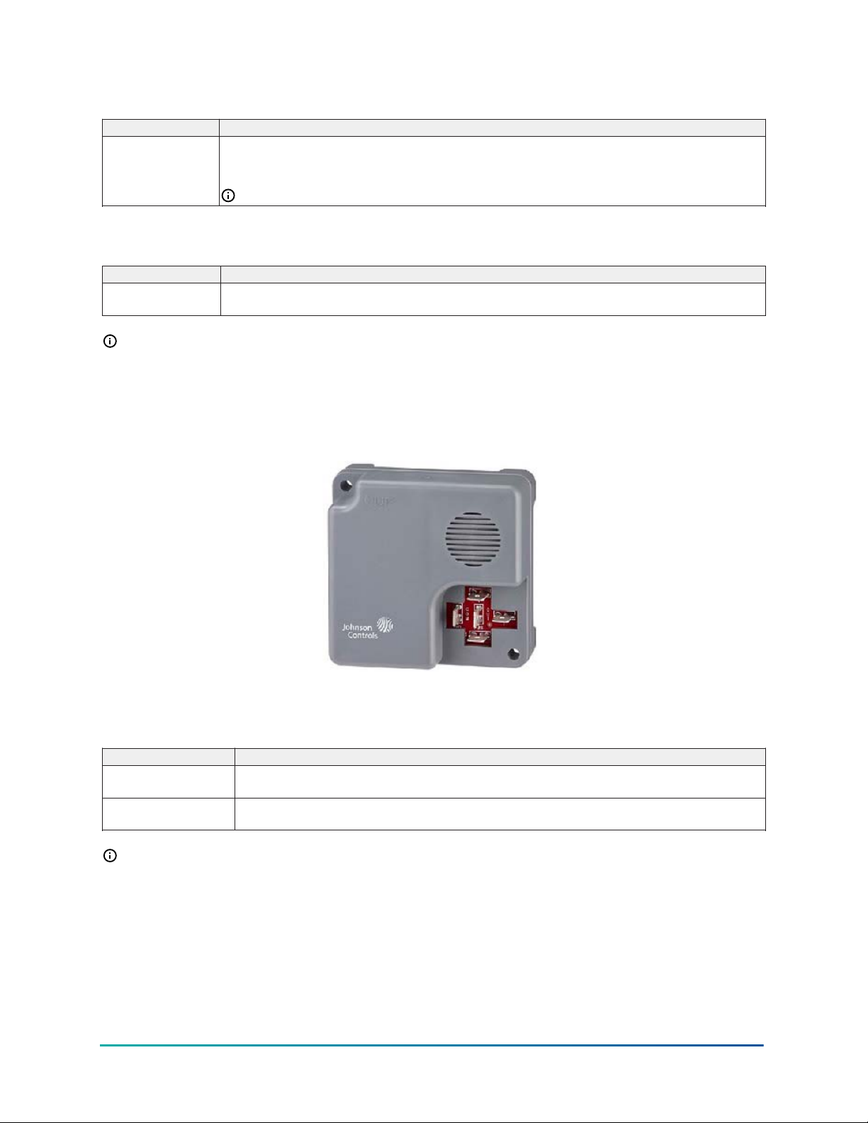
Table 17: System 450 compatible TE-68NT-0N00S 1,000 Ohms Nickel temperature sensor
ordering information
Product code Description
TE-68NT-0N00S TE6800 Series 1,000 ohms at 21°C (70° F) nickel temperature sensor for wall-mount applications. For
more information, including sensor description, technical specifications, and mounting accessories,
refer to the TE-6800 Series Temperature Sensors Product Bulletin (LIT-12011542).
Note: For correct readings, set the temperature sensor to HI°C or HI°F.
Table 18: System 450 compatible HE-69xx type humidity sensors with 100 ohm NTC nickel
temperature sensor ordering information
Product code Description
HE-69S20NP Duct Mount Humidity Sensor with 1,000 ohm NTC nickel temperature sensor: 10 to 90% RH;-40 to
121°C (-40 to 250° F)
Note: The HE-69xx0NP sensors require 24 VAC input and must use the 0–5 VDC output. Refer
to the HE-69xx0NP Duct Probe Humidity Element with Temperature Sensor Installation Guide (Part
No. 24-11025-00013) for more information, including technical specifications, and mounting
accessories.
Figure 32: HE-69xx
Table 19: System 450 compatible HE6800 Series humidity transmitters with temperature
sensor ordering information
Product code Description
HE-68N2-0N00WS Wall Mount Humidity Transmitter with Nickel Temperature Sensor: 10 to 90 ±2% RH;0 to 55°C (32 to
131° F)
HE-68N3-0N00WS Wall Mount Humidity Transmitter with Nickel Temperature Sensor: 10 to 90 ±2% RH;0 to 55°C (32 to
131° F)
Note: The HE-6800 transmitters require 24 VAC input and must use the 0–5 VDC output.
Refer to the HE-6800 Series Humidity Transmitters with Temperature Sensor Product Bulletin
(LIT-12011625) for more information, including technical specifications and mounting
accessories. Note the use of Hi F sensor setting for 1 K ohm Nickel temperature sensors.
59System 450 Series Modular Control Systems with Standard Control Modules Technical Bulletin
Page 60
Table 20: System 450 compatible low pressure differential transducer ordering information
Product code Description
DPT2650-0R5D-AB Low Pressure Differential Transducer: 0 to 0.5 in. W.C. (System 450 Sensor Type: P 0.5)
DPT2650-2R5D-AB Low Pressure Differential Transducer: 0 to 2.5 in. W.C. (System 450 Sensor Type: P 2.5)
DPT2650-005D-AB Low Pressure Differential Transducer: 0 to 5.0 in. W.C. (System 450 Sensor Type: P 5)
DPT2650-10D-AB Low Pressure Differential Transducer: 0 to 10 in. W.C. (System 450 Sensor Type: P 10)
Note:
• Refer to the Setra Systems Model DPT265 Very Low Differential Pressure Transducer Catalog
Page.
• The DPT265 sensors require 24 VAC input and must use the 0–5 VDC output. Refer to the
Setra Systems Model DPT265 Very Low Differential Pressure Transducer Catalog Page.
Table 21: System 450 compatible P599 Series transducers with 1/4 in. SAE 45 flare internal
thread with depressor (Style 47) ordering information
Product Code Description Availability
P599RCPS401C -1 to 8 bar; order WHA-PKD3 type wire harness separately. Only available in Europe
P599RCPS402C -1 to 15 bar; order WH A-PKD3 type wire harness separately. Only available in Europe
P599RCPS402C 0 to 30 bar; order WHA-PKD3 type wire harness separately. Only available in Europe
P599RCPS405C 0 to 50 bar; order WHA-PKD3 type wire harness separately. Only available in Europe
P599RCPS100C -10 to 100 psis (sealed for wet and freeze/thaw applications); order WHA-
PKD3 type wire harness separately.
P599RCPS100K -10 to 100 psis (sealed for wet and freeze/thaw applications); WHA-
PKD3-200C wire harness included.
P599RCPS102C 0 to 200 psis (sealed for wet and freeze/thaw applications); order WHA-
PKD3 type wire harness separately.
P599RCPS102K 0 to 200 psis (sealed for wet and freeze/thaw applications); WHA-
PKD3-200C wire harness included.
P599RCPS101C 0 to 100 psig; order WHA-PKD3 type wire harness separately. Only available in North
P599RCPS101K 0 to 100 psig; WHA-PKD3-200C wire harness included. Only available in North
P599RCPS105C 0 to 500 psig; order WHA-PKD3 type wire harness separately. Only available in North
P599RCPS105K 0 to 500 psig; WHA-PKD3-200C wire harness included. Only available in North
P599RCPS107C 0 to 750 psig; order WHA-PKD3 type wire harness separately. Only available in North
P599RCPS107K 0 to 750 psig; WHA-PKD3-200C wire harness included. Only available in North
Only available in North
America
Only available in North
America
Only available in North
America
Only available in North
America
America
America
America
America
America
America
Note: The P599 sensors must be powered with the +5 VDC and C terminals and the output is
0.5 to 4.5 VDC. Refer to the P599 Series Electronic Pressure Transducers Product/Technical Bulletin
(LIT-12012446).
Table 22: System 450 compatible P599 Series transducers with 1/8 in. 27 NPT external thread
(Style 49) ordering information
Product code Description
P599RAPS100C -10 to 100 psis (sealed for wet and freeze/thaw applications); order a WHA-PKD3 type wire harness
separately.
P599RAPS100K -10 to 100 psis (sealed for wet and freeze/thaw applications); WHA-PKD3-200C wire harness
included.
P599RAPS101C 0 to 100 psig; order a WHA-PKD3 type wire harness separately.
P599RAPS101K 0 to 100 psig; WHA-PKD3-200C wire harness included.
System 450 Series Modular Control Systems with Standard Control Modules Technical Bulletin60
Page 61
Table 22: System 450 compatible P599 Series transducers with 1/8 in. 27 NPT external thread
(Style 49) ordering information
Product code Description
P599RAPS102C 0 to 200 psig; order a WHA-PKD3 type wire harness separately.
P599RAPS105C 0 to 500 psig; order WHA-PKD3 type wire harness separately.
P599RAPS105K 0 to 500 psig; WHA-PKD3-200C wire harness included.
P599RAPS107C 0 to 750 psig; order WHA-PKD3 type wire harness separately.
P599RAPS107K 0 to 750 psig; WHA-PKD3-200C wire harness included.
Note: The P599 sensors must be powered with the +5 VDC and C terminals and the output is
0.5 to 4.5 VDC. Refer to the P599 Series Electronic Pressure Transducers Product/Technical Bulletin
(LIT-12012446).
Table 23: WHA-PKD3 Wire Harnesses ordering information
Product code Description
WHA-PKD3-200C Plug and 3-Wire Harness for P599 Electronic Pressure Transducers: 2.0 m (6.5 ft) cable
WHA-PKD3-400C Plug and 3-Wire Harness for P599 Electronic Pressure Transducers: 4.0 m (13 ft) cable
WHA-PKD3-600C Plug and 3-Wire Harness for P599 Electronic Pressure Transducers: 6.0 m (19.6 ft) cable
Note: Refer to the P599 Series Electronic Pressure Transducers Product/Technical Bulletin
(LIT-12012446).
Related documentation
Table 24 provides references to System 450 related documentation, including sensor installation
instructions.
Table 24: Related documentation
For information about See document LIT or Part Number
System 450 Series Features, Benefits, Models,
and Technical Specifications
System 450 Series Features, Benefits, Models,
and Technical Specifications
Installing, Wiring, and Setting up System 450
Control Modules with Relay Output
Installing, Wiring, and Setting up System 450
Control Modules with Analog Output
Installing, Wiring, and Setting up System 450
Control Modules with Hybrid Analog Output
and High Input Signal Selection
Installing and Wiring System 450 Expansion
Modules with Relay Output
Installing and Wiring System 450 Expansion
Modules with Analog Output
Installing and Wiring the System 450 Power
Module
Installing and Wiring the A99 Series
Temperature Sensors
Installing and Wiring the TE-6000 Series
Temperature Sensing Elements
Installing and Wiring the TE-6300P Series
Temperature Sensors
Installing and Wiring the TE-6300M Series Well
Insertion Temperature Sensors
System 450 Series Modular Controls Product
Bulletin
System 450 Series Modular Controls Catalog Page LIT-1900549
System 450 Series Control Modules with Relay
Outputs Installation Instructions
System 450 Series Control Modules with Analog
Outputs Installation Instructions
System 450 Series Control Module with Hybrid
Analog Output and High Input Signal Selection
Installation Instructions
System 450 Series Expansion Modules with Relay
Outputs Installation Instructions
System 450 Series Expansion Modules with Analog
Outputs Installation Instructions
System 450 Series Power Module Installation
Instructions
A99B Series Temperature Sensors Product/
Technical Bulletin
TE-6000 Series Temperature Sensing Elements
Installation Instructions
TE-6300P Series Temperature Sensors Installation
Instructions
TE-6300M Series Well Insertion Temperature
Sensors Installation Instructions
LIT-12011458
Part No. 24-7664-3025
Part No. 24-7664-3191
Part No. 24-7664-2802
Part No. 24-7664-2861
Part No. 24-7664-2799
Part No. 24-7664-2691
LIT-125186,
Part No. 24-7664-1636
Part No. 24-4034-26
Part No. 24-4034-107
Part No. 24-4034-182
61System 450 Series Modular Control Systems with Standard Control Modules Technical Bulletin
Page 62
Table 24: Related documentation
For information about See document LIT or Part Number
Installing and Wiring the TE-6300P Series
Outdoor Air Temperature Sensors
Installing and Wiring the TE-6300V Series
Flange Mount Duct Averaging Temperature
Sensors
Installing and Wiring the TE-6300P Series Wall
Mount Temperature Sensors
Installing and Wiring the TE-6300M Series Duct
Averaging Temperature Sensors
Installing and Wiring the TE-6300F Series Flush
Mount Sensors
Installing and Wiring the TE-6300A Series
Adjustable Length Duct Probe Temperature
Sensors
Installing and Wiring the TE-6300V Series
Flange Mount Duct Probe Temperature
Sensors
Installing and Wiring the TE-6300M Series Duct
Probe Temperature Sensors
Installing and Wiring the TE-6800 Series
Temperature Sensors
Installing and Wiring the P599 Series Electronic
Pressure Transducers
Installing and Wiring the HE-6800 Humidity
Sensors and Humidity with Temperature
Sensors
Installing and Wiring the HE-6900 Humidity
Sensors and Humidity with Temperature
Sensors
Installing and Wiring Setra Systems Model 265
Differential Pressure Transducers
TE-6300P Series Outdoor Air Temperature Sensors
Installation Instructions
TE-6300V Series Flange Mount Duct Averaging
Temperature Sensors Installation Instructions
TE-6300P Series Wall Mount Temperature Sensors
Installation Instructions
TE-6300M Series Duct Averaging Temperature
Sensors Installation Instructions
TE-6300F Series Flush Mount Sensors Installation
Instructions
TE-6300A Series Adjustable Length Duct Probe
Temperature Sensors Installation Instructions
TE-6300V Series Flange Mount Duct Probe
Temperature Sensors Installation Instructions
TE-6300M Series Duct Probe Temperature Sensors
Installation Instructions
TE-6800 Series Temperature Sensors Installation
Instructions
P599 Series Electronic Pressure Transducers
Product/Technical Bulletin
HE-6800 Series Humidity Transmitters with
Temperature Sensor Installation Guide
HE-69xxONP Duct Probe Humidity Element with
Temperature Sensor Installation Guide
Setra Systems Model 265 Differential Pressure
Transducer Installation Guide
Part No. 24-4034-190
Part No. 24-4034-220
Part No. 24-4034-204
Part No. 24-4034-174
Part No. 24-4034-255
Part No. 24-4034-247
Part No. 24-4034-212
Part No. 24-4034-166
Part No. 24-10409-1
LIT-12012446,
Part No. 24-7664-3264
Part No. 24-10409-28
Part No. 24-11025-00013
Search Johnson Controls
documentation for Setra
System Model 265.
System 450 Series Modular Control Systems with Standard Control modules technical specifications
Table 25: C450CPN-4 and C450CQN-4 control modules with analog output technical
specifications
Specification Description
Product C450CPN-4 and C450CQN-4: System 450 Control Module models are sensing controls
and operating controls with LCD, four-button touchpad, and SPDT analog output
C450CPN-4: Control Module with one analog output
C450CQN-4: Control Module with two analog outputs
Power consumption C450CPN-4: 1.3 VA maximum using 0–10 V out; 1.5 VA maximum using 4–20 mA out
Supply power Internal Supply Power: C450YNN-1C Power Supply Module
Ambient operating conditions Temperature: -40 to 66°C (-40 to 150°F) when using 0–10 VDC outputs;-40 to 40°C (-40 to
System 450 Series Modular Control Systems with Standard Control Modules Technical Bulletin62
C450CQN-4: 2.0 VA maximum using 0–10 V out; 2.4 VA maximum using 4–20 mA out
External Supply Power: 24 VAC (20–30 VAC) Safety Extra-Low Voltage (SELV) (Europe),
Class 2 (North America), 50/60 Hz, 10 VA minimum
Note: A System 450 control module or module assembly can use an internal or an
external supply power source, but must not be connected to both simultaneously.
104°F) when using 4-20 mA outputs
Humidity: Up to 95% RH non-condensing; Maximum Dew Point 29°C (85°F)
Page 63
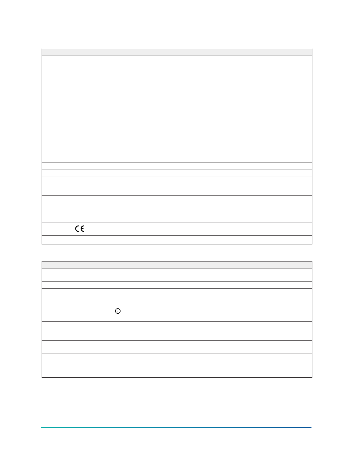
Table 25: C450CPN-4 and C450CQN-4 control modules with analog output technical
specifications
Specification Description
Ambient shipping and storage
conditions
Input signal 0–5 VDC for humidity sensors and static pressure transducers
Analog output
Analog input accuracy Resolution: 14 bit
Enclosure Type 1, IP20 High-Impact Thermoplastic
Dimensions (H x W x D) 127 x 61 x 61 mm (5.00 x 2.38 x 2.38 in.)
Weight C450CPN-4: 195 g (0.43 lb)
Compliance United States: UL 60730-1, File E27734; FCC Compliant to CFR47, Part 15, Subpart B, Class
Temperature: -40 to 80°C (-40 to 176°F)
Humidity: Up to 95% RH non-condensing; Maximum Dew Point 29°C (85°F)
0.5–4.5 VDC for ratiometric pressure transducers
1,035 ohms at 25°C (77°F) for A99 PTC temperature sensors
1,000 ohms at 21.1°C (70°F) for TE-6xxx Nickel temperature sensors
Voltage Mode (0–10 VDC):
10 VDC maximum output voltage
10 mA maximum output current
Requires an external load of 1,000 ohms or more
The AO operates in Voltage Mode when connected to devices with impedance greater
than 1,000 ohms. Devices that fall below 1,000 ohms may not operate as intended with
Voltage Mode applications.
Current Mode (4–20 mA):
Requires an external load between 0–300 ohms
The AO operates in Current Mode when connected to devices with impedance less than
300 ohms. Devices that rise above 300 ohms may not operate as intended with Current
Mode applications.
C450CQN-4: 195 g (0.43 lb)
B limits
Canada: cULus Listed; CAN/CSA-E60730-1, File E27734; Industry Canada (IC) Compliant
to Canadian ICES-003, Class B limits
Europe: CE Mark – Johnson Controls declares that this product is in compliance with the
essential requirements and other relevant provisions of the EMC Directive.
Australia and New Zealand: RCM mark, Australia/NZ emissions compliant
Table 26: C450CPW-400C control module with hybrid analog output technical specifications
Specification Description
Product C450CPW-400C System 450 control module is a sensing control and operating control with
LCD, four-button touchpad, and analog output with pulse-width modulation capability.
Power consumption C450CPW-400C: 1.3 VA maximum using 0–10 V out; 1.5 VA maximum using 4–20 mA out
Supply power Internal Supply Power: C450YNN-1C Power Supply Module
Ambient operating conditions Temperature: -40 to 66°C (-40 to 150°F) when using 0–10 VDC outputs;-40 to 40°C (-40 to
Ambient shipping and storage
conditions
Input signal 0–5 VDC for humidity sensors and static pressure transducers
External Supply Power: 24 VAC (20–30 VAC) Safety Extra-Low Voltage (SELV) (Europe), Class
2 (North America), 50/60 Hz, 10 VA minimum
Note: A System 450 control module or module assembly can use an internal or an
external supply power source, but must not be connected to both simultaneously.
104°F) when using 4–20 mA outputs
Humidity: Up to 95% RH non-condensing; Maximum Dew Point 29°C (85°F)
Temperature: -40 to 80°C (-40 to 176°F)
Humidity: Up to 95% RH non-condensing; Maximum Dew Point 29°C (85°F)
0.5–4.5 VDC for ratiometric pressure transducers
1,035 ohms at 25°C (77°F) for A99 PTC temperature sensors
1,000 ohms at 21.1°C (70°F) for TE-6xxx Nickel temperature sensors
63System 450 Series Modular Control Systems with Standard Control Modules Technical Bulletin
Page 64
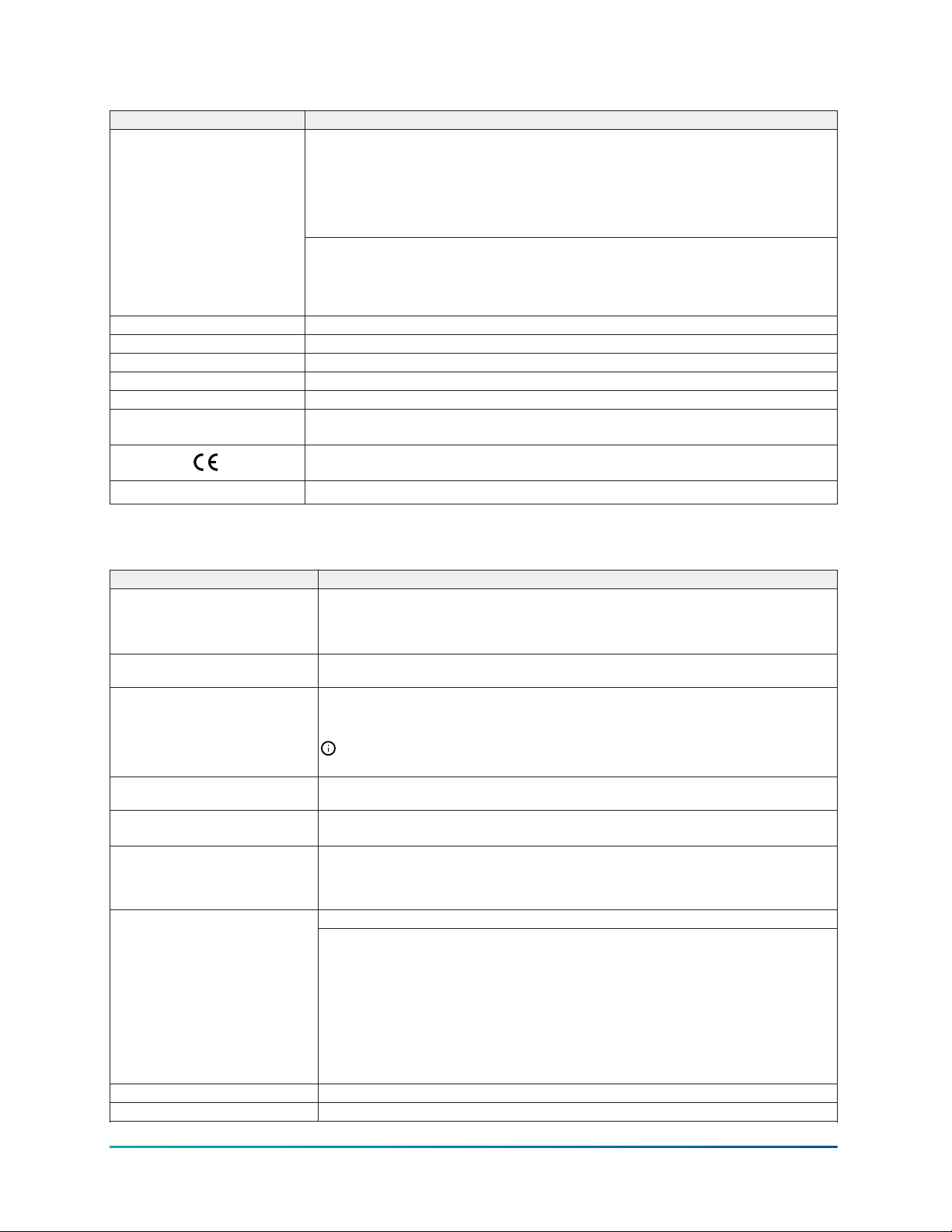
Table 26: C450CPW-400C control module with hybrid analog output technical specifications
Specification Description
Analog output
Analog input accuracy Resolution: 14 bit
Enclosure Type 1, IP20 High-Impact Thermoplastic
Dimensions (H x W x D) 127 x 61 x 61 mm (5.00 x 2.38 x 2.38 in.)
Weight C450CPW-400C: 195 g (0.43 lb)
Compliance United States: UL 60730-1, File E27734; FCC Compliant to CFR47, Part 15, Subpart B, Class B
Voltage Mode (0–10 VDC):
10 VDC maximum output voltage
10 mA maximum output current
Requires an external load of 1,000 ohms or more
The AO operates in Voltage Mode when connected to devices with impedance greater than
1,000 ohms. Devices that fall below 1,000 ohms may not operate as intended with Voltage
Mode applications.
Current Mode (4–20 mA):
Requires an external load between 0–300 ohms
The AO operates in Current Mode when connected to devices with impedance less than
300 ohms. Devices that rise above 300 ohms may not operate as intended with Current
Mode applications.
Canada: cULus Listed; CAN/CSA-E60730-1, File E27734; Industry Canada (IC) Compliant to
Canadian ICES-003, Class B limits
Europe: CE Mark – Johnson Controls declares that this product is in compliance with the
essential requirements and other relevant provisions of the EMC Directive.
Australia and New Zealand: RCM mark, Australia/NZ emissions compliant
Table 27: C450CBN-4 and C450CCN-4 control modules with relay output technical
specifications
Specification Description
Product C450CBN-4 and C450CCN-4: System 450 Control Module models are sensing controls
and operating controls with LCD, four-button touchpad, and SPDT relay output
C450CBN-4: Control Module with one SPDT output relay
C450CCN-4: Control Module with two SPDT output relays
Power consumption C450CBN-4: 0.9 VA maximum
Supply power Internal Supply Power: C450YNN-1C Power Supply Module
Ambient operating conditions Temperature: -40 to 66°C (-40 to 150 ° F)
Ambient shipping and storage
conditions
Input signal 0–5 VDC for humidity sensors and static pressure transducers
Analog input accuracy Resolution: 14 bit
Enclosure Type 1, IP20 High-Impact Thermoplastic
C450CCN-4: 1.3 VA maximum
External Supply Power: 24 VAC (20–30 VAC) Safety Extra-Low Voltage (SELV) (Europe),
Class 2 (North America), 50/60 Hz, 10 VA minimum
Note: A System 450 control module or module assembly can use an internal or an
external supply power source, but must not be connected to both simultaneously.
Humidity: Up to 95% RH non-condensing; Maximum Dew Point 29°C (85°F)
Temperature: -40 to 80°C (-40 to 176°F)
Humidity: Up to 95% RH non-condensing; Maximum Dew Point 29°C (85°F)
0.5–4.5 VDC for ratiometric pressure transducers
1,035 ohms at 25°C (77°F) for A99 PTC temperature sensors
1,000 ohms at 21.1°C (70°F) for TE-6xxx Nickel temperature sensors
General: 1/2 HP at 120/240 VAC, SPDTOutput relay contacts
Specific:
AC Motor Ratings 120 VAC
• AC Full-load Amperes: 9.8 A
• Locked-Rotor Amperes: 58.8 A
AC Motor Ratings 208/240 VAC
• AC Full-load Amperes: 4.9 A
• Locked-Rotor Amperes: 29.4 A
10 Amperes AC Non-inductive at 24/240 VAC
Pilot Duty: 125 VA at 24/240 VAC
System 450 Series Modular Control Systems with Standard Control Modules Technical Bulletin64
Page 65
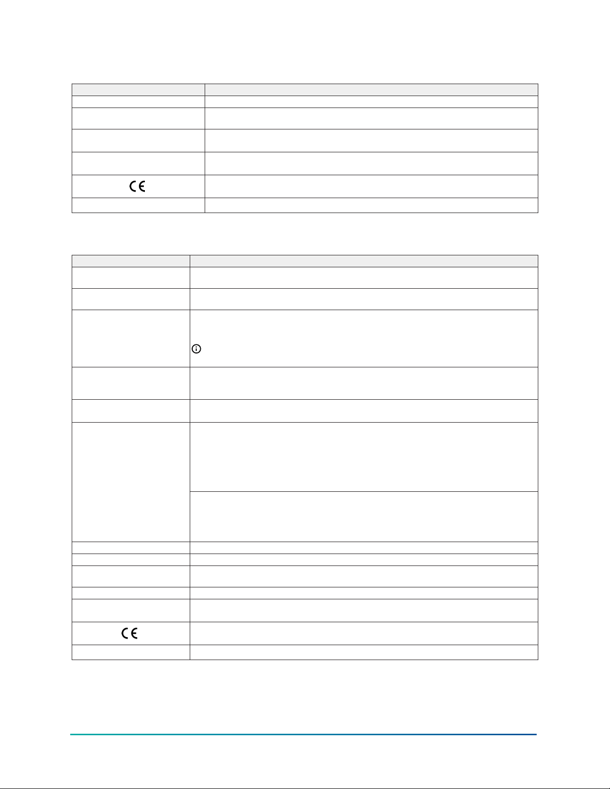
Table 27: C450CBN-4 and C450CCN-4 control modules with relay output technical
specifications
Specification Description
Dimensions (H x W x D) 127 x 61 x 61 mm (5.00 x 2.38 x 2.38 in.)
Weight C450CBN-4: 209 g (0.46 lb)
Compliance United States: UL 60730-1, File E27734; FCC Compliant to CFR47, Part 15, Subpart B, Class
C450CCN-4: 222 g (0.49 lb)
B
Canada: cULus Listed; CAN/CSA-E60730-1, File E27734; Industry Canada (IC) Compliant
to Canadian ICES-003, Class B limits
Europe: CE Mark – Johnson Controls declares that this product is in compliance with the
essential requirements and other relevant provisions of the EMC Directive.
Australia and New Zealand: RCM mark, Australia/NZ emissions compliant
Table 28: C450SPN-4C and C450SQN-4C expansion modules with analog output technical
specifications
Specification Description
Product C450SPN-4C: System 450 Expansion Module with one Analog Output
Power consumption C450SPN-4C: 1.1 VA max using 0–10 V out; 1.3 VA maximum using 4–20 mA out
Supply power Internal Supply Power: C450YNN-1C Power Supply Module
Ambient operating conditions Temperature: -40 to 66°C (-40 to 150°F) when using 0–10 VDC outputs;-40 to 40 ° C (-40 to
Ambient shipping and storage
conditions
Analog output
Enclosure Type 1, IP20 High-Impact Thermoplastic
Dimensions (H x W x D) 127 x 61 x 61 mm (5.00 x 2.38 x 2.38 in.)
Weight C450SPN-4C: 150 g (0.33 lb)
Compliance United States: UL 60730-1, File E27734; FCC Compliant to CFR47, Part 15, Subpart B,Class B
C450SQN-4C: System 450 Expansion Module with two Analog Outputs
C450SQN-4C: 1.8 VA max using 0–10 V out; 2.2 VA maximum using 4–20 mA out
External Supply Power: 24 VAC (20–30 VAC) Safety Extra-Low Voltage (SELV) (Europe), Class 2
(North America), 50/60 Hz, 10 VA minimum
Note: A System 450 control module or module assembly can use an internal or an
external supply power source, but must not be connected to both simultaneously.
104°F) when using 4–20 mA outputs
Humidity: Up to 95% RH non-condensing; Maximum Dew Point 29°C (85°F)
Temperature: -40 to 80°C (-40 to 176°F)
Humidity: Up to 95% RH non-condensing; Maximum Dew Point 29°C (85°F)
Voltage Mode (0–10 VDC):
10 VDC maximum output voltage
10 mA maximum output current
Requires an external load of 1,000 ohms or more
The AO operates in Voltage Mode when connected to devices with impedance greater than
1,000 ohms. Devices that fall below 1,000 ohms may not operate as intended with Voltage
Mode applications.
Current Mode (4–20 mA):
Requires an external load between 0–300 ohms
The AO operates in Current Mode when connected to devices with impedance less than 300
ohms. Devices that rise above 300 ohms may not operate as intended with Current Mode
applications.
C450SQN-4C: 150 g (0.33 lb)
Canada: cULus Listed; CAN/CSA-E60730-1, File E27734; Industry Canada (IC) Compliant to
Canadian ICES-003, Class B limits
Europe: CE Mark – Johnson Controls declares that this product is in compliance with the
essential requirements and other relevant provisions of the EMC Directive.
Australia and New Zealand: RCM mark, Australia/NZ emissions compliant
65System 450 Series Modular Control Systems with Standard Control Modules Technical Bulletin
Page 66
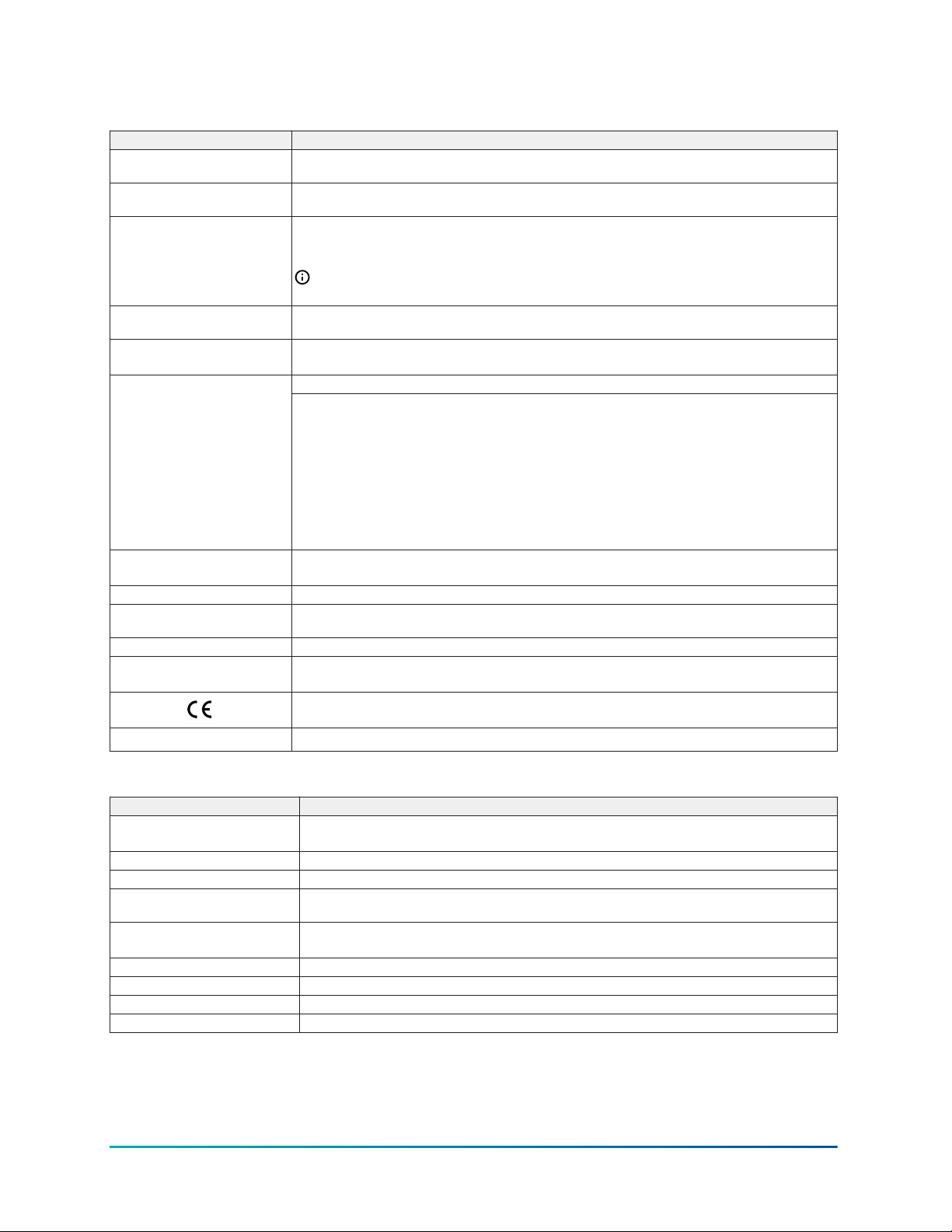
Table 29: C450SBN-4C and C450SCN-4C expansion modules with relay output technical
specifications
Specification Description
Product C450SBN-4C: System 450 Expansion Module with one SPDT output relay
Power consumption C450SBN-4C: 0.8 VA maximum
Supply power Internal Supply Power: C450YNN-1C Power Supply Module
Ambient operating conditions Temperature: -40 to 66°C (-40 to 150°F)
Ambient shipping and storage
conditions
Control construction Independently mounted control, surface mounted with Lexan® 950 enclosure suitable for
Dimensions (H x W x D) 127 x 61 x 61 mm (5.00 x 2.38 x 2.38 in.)
Weight C450SBN-4C: 172 g (0.38 lb)
Compliance United States: UL 60730-1, File E27734; FCC Compliant to CFR47, Part 15, Subpart B,Class B
C450SCN-4C: System 450 Expansion Module with two SPDT output relays
C450SCN-4C: 1.2 VA maximum
External Supply Power: 24 VAC (20–30 VAC) Safety Extra-Low Voltage (SELV) (Europe), Class 2
(North America), 50/60 Hz, 10 VA minimum
Note: A System 450 control module or module assembly can use an internal or an
external supply power source, but must not be connected to both simultaneously.
Humidity: Up to 95% RH non-condensing; Maximum Dew Point 29°C (85°F)
Temperature: -40 to 80°C (-40 to 176°F)
Humidity: Up to 95% RH non-condensing; Maximum Dew Point 29°C (85°F)
General: 1/2 HP at 120/240 VAC, SPDTOutput relay contacts
Specific:
AC Motor Ratings 120 VAC
• AC Full-Load Amperes: 9.8 A
• AC Locked-Rotor Amperes: 58.8 A
AC Motor Ratings 208/240 VAC
• AC Full-Load Amperes: 4.9 A
• AC Locked-Rotor Amperes: 29.4 A
10 Amperes AC Non-inductive at 24/240 VAC
Pilot Duty: 125 VA at 24/240 VAC
DIN rail mounting or direct mounting to a hard, even surface.
C450SCN-4C: 186 g (0.41 lb)
Canada: cULus Listed; CAN/CSA-E60730-1, File E27734; Industry Canada (IC) Compliant to
Canadian ICES-003, Class B limits
Europe: CE Mark – Johnson Controls declares that this product is in compliance with the
essential requirements and other relevant provisions of the EMC Directive.
Australia and New Zealand: RCM mark, Australia/NZ emissions compliant
Table 30: C450YNN-1C power supply module technical specifications
Specification Description
Product C450YNN-1C: System 450 Power Supply Module; 120 or 240 VAC stepdown to 24 VAC Class 2
(North America) or SELV (Europe)
Supply power 110/120 VAC or 220/240 VAC at 50/60 Hz (100 mA maximum)
Secondary power 24 VAC, 10 VA
Ambient operating conditions Temperature: -40 to 66°C (-40 to 150°F)
Ambient shipping and storage
Conditions
Enclosure Type 1, IP20 High-Impact Thermoplastic
Dimensions (H x W x D) 127 x 61 x 61 mm (5.00 x 2.38 x 2.38 in.)
Weight C450YNN-1C: 390 gm (0.86 lb)
Compliance United States: UL 60730-1, File E27734; FCC Compliant to CFR47, Part 15, Subpart B,Class B
Humidity: Up to 95% RH non-condensing; Maximum Dew Point 29°C (85°F)
Temperature: -40 to 80°C (-40 to 176°F)
Humidity: Up to 95% RH non-condensing; Maximum Dew Point 29°C (85°F)
System 450 Series Modular Control Systems with Standard Control Modules Technical Bulletin66
Page 67
Table 30: C450YNN-1C power supply module technical specifications
Specification Description
Canada: cULus Listed; CAN/CSA-E60730-1, File E27734; Industry Canada (IC) Compliant to
Canadian ICES-003, Class B limits
Europe: CE Mark – Johnson Controls declares that this product is in compliance with the
essential requirements and other relevant provisions of the EMC Directive and the Low
Voltage Directive.
Australia and New Zealand: RCM mark, Australia/NZ emissions compliant
The performance specifications are nominal and conform to acceptable industry standards. For
application at conditions beyond these specifications, Johnson Controls shall not be liable for
damages resulting from misapplication or misuse of its products.
North American emissions compliance
United States
This equipment has been tested and found to comply with the limits for a Class B digital device,
pursuant to Part 15 of the FCC Rules. These limits are designed to provide reasonable protection
against harmful interference in a residential installation. This equipment generates, uses and can
radiate radio frequency energy and, if not installed and used in accordance with the instructions,
may cause harmful interference to radio communications. However, there is no guarantee that
interference will not occur in a particular installation. If this equipment does cause harmful
interference to radio or television reception, which can be determined by turning the equipment
off and on, the user is encouraged to try to correct the interference by one or more of the following
measures:
• Reorient or relocate the receiving antenna.
• Increase the separation between the equipment and receiver.
• Connect the equipment into an outlet on a circuit different from that to which the receiver is
connected.
• Consult the dealer or an experienced radio/TV technician for help.
Warning (Part 15.21)
Changes or modifications not expressly approved by the party responsible for compliance could
void the user’s authority to operate the equipment.
Canada
This Class (B) digital apparatus meets all the requirements of the Canadian Interference-Causing
Equipment Regulations.
Cet appareil numérique de la Classe (B) respecte toutes les exigences du Règlement sur le matériel
brouilleur du Canada.
Industry Canada Statement(s)
This device complies with Industry Canada licence-exempt RSS standard(s). Operation is subject to
the following two conditions:
1. This device may not cause interference, and
2. This device must accept any interference, including interference that may cause undesired
operation of the device.
67System 450 Series Modular Control Systems with Standard Control Modules Technical Bulletin
Page 68

Le présent appareil est conforme aux CNR d'Industrie Canada applicables aux appareils radio
exempts de licence. L'exploitation est autorisée aux deux conditions suivantes :
1. L'appareil ne doit pas produire de brouillage, et
2. L'utilisateur de l'appareil doit accepter tout brouillage radioélectrique subi, même si le
brouillage est susceptible d'en compromettre le fonctionnement.
Glossary of terms
°C
Degrees Celsius (°C) appears in the Main (sensor status) screens, along with the current sensed
temperature value, when a Celsius temperature sensor is set up in your control system. °C also
designates a Sensor Type that is available when you set up the sensors in the Sensor Setup
screens. See Accessing and Navigating the User Interface and System 450 Compatible Sensors and
Transducers for more information.
°F
Degrees Fahrenheit (°F) appears in the Main (sensor status) screens, along with the current sensed
temperature value, when a Fahrenheit temperature sensor is set up in your control system. °F
also designates a Sensor Type that is available when you set up the sensors in the Sensor Setup
screens. See Accessing and Navigating the User Interface and System 450 Compatible Sensors and
Transducers for more information.
Analog Output
System 450 provides self-selecting 0 to 10 VDC signal or 4 to 20 mA signal analog outputs. The
analog outputs can be set up to provide a wide variety of direct and reverse acting proportional
control applications, including multi-stage control and proportional plus integral control. Analog
outputs are identified in the System 450 UI as OUTA in the Output Setup Start screens and with a
percent signal strength and control ramp icon in the System Status screens. See Analog Outputs,
Analog Output Setup, and Viewing the System Status Screens for more information.
bAR
bAR appears in the Main (sensor status) screens along with the current sensed pressure value,
when your control system uses one or more pressure transducers with P 8, P 15, P 30, or P 50
Sensor Types. Bar is an SI (International System) unit of measurement for the pressure value
displayed in the Main screens. One bar is equal to approximately one atmosphere of pressure, 14.5
psi, and 100 kPa. See System 450 Sensors and Transducers for Standard Control Modules for more
information.
bin
The Binary Input (bin) sensor provides relay output control using an external (user-supplied) binary
input or set of dry contacts to control the relay output state (On or Off) based on the binary input
state (closed or open). A binary input can be connected to the Sn1, Sn2, or Sn3 terminals and a C
terminal on the control module. See Binary Input Control for Relay Outputs for more information.
bKLT
The backlight brightness level feature allows you to adjust the LCD backlight intensity. bKLL OFF =
the backlight is off. bKLH 10 = the brightest backlight setting and the system default. The selected
backlight brightness level is applied to the LCD during normal operation. When you enter the
programming menus to set up the control or press any key, the LCD automatically goes to the
brightest level. If no key is pressed for 30 seconds, the main screen is displayed and the backlight
settingreverts to the selected brightness level.
System 450 Series Modular Control Systems with Standard Control Modules Technical Bulletin68
Page 69

bNd
In the Output Signal Deadband (bNdx) screen in the Analog Output Setup screens, select the output
deadband value (as a percentage of the total output signal range). You can select a value between 0
and 50 (percent).
Control Module
The primary module in a System 450 control system, and sometimes the only module in standalone control systems. Each System 450 control system has only one control module, which
contains the control system processor, firmware, memory, and LCD. The control module receives
the input signals from the system sensors, and it monitors and controls all of the system outputs,
including the expansion module outputs. There are four types of System 450 control modules:
standard control modules, reset control modules, hybrid analog output control modules, and
communications control modules. See Control Module and User Interface and Repair and Ordering
Information for more information.
x
dEP
In the Differential End Point (dEPx) screen in the Analog Output Setup screens, select the differential
value that analog output number x is driving the controlled loop or process away from. The dEP
value, along with Differential Setpoint (dSP) value, establishes the output’s proportional control
band. The dEP screen appears in the Analog Output Setup screens after you set up and select the
Differential Sensor (Sn-d) for the output reference. See Differential Control for more information.
Differential Control
The Differential Control feature is used to monitor and maintain a selected difference in a condition
(temperature, pressure, or humidity) between two sensor points within a system, process, or space.
See Differential Control for more information.
Direct Acting
With Direct Acting proportional control, an increase in the sensor signal results in a proportional
increase of the output signal generated to the controlled equipment and vice versa. See Direct and
Reverse Control Actions for Analog Outputs for more information.
x
dSP
In the Differential Setpoint (dSPx) screen in the Analog Output Setup screens, select the target
differential value that analog output number x is driving the controlled loop towards. The dSP
value, along with Differential End Point (dEP) establishes the output’s proportional control band.
The dSP screen appears in the Analog Output Setup screens after you select the Differential Sensor
(Sn-d) for the output reference. See Differential Control for more information.
EC Motor
Brushless, low-radio-frequency emitting motors, available in variable-speed (full-range modulating)
motor models, multiple-speed (selectable fixed-speeds) motor models, and models capable
of being set up as either variable or multiple speed motors. Electronically Commutated (EC)
motors are quiet, clean, energy-efficient motors that operate efficiently at low speeds. PENN by
Johnson Control EC motors provide a wide range of models for both indoor and outdoor HVAC/R
applications. The System 450 control module with hybrid analog output (C450DPW-100) is designed
to enhance and optimize EC motor operation at very low speeds. See Sensor Failure Mode, Hybrid
Analog and High Input Signal Selection Control System Example, and Setting up a Pulse Region
Hybrid Analog Output for more information.
69System 450 Series Modular Control Systems with Standard Control Modules Technical Bulletin
Page 70

x
EP
In the End Point Selection (EPx) screen in the Analog Output Setup screens, select the condition
value that analog output number x is driving the control loop away from and towards the Setpoint
(SP) value. The EP and SP values define the proportional band that the analog output is intended to
control the condition within. See Direct and Reverse Control Actions for Analog Outputs for more
information.
Expansion Modules
Provide additional relay or analog outputs to your control system. Expansion module models
are available with one or two relay outputs, and one or two analog outputs. All of the outputs in
a control system, including the Expansion module outputs are set up in the control module UI.
System 450 control systems can control up to 10 outputs, which can be any combination of relay or
analog outputs. See Expansion Modules, Module Assemblies, and Outputs and Repair and Ordering
Information for more information.
Functional Sensor
In addition to the wide variety of System 450 compatible hard-wired temperature, pressure, and
humidity sensors available, the System 450 firmware also enables several functional sensors based
on the input from one or more of the hard-wired sensors in your control system. Functional sensors
include: the Reset Setpoint sensor (rES), which enables reset control, setback control, and run-time
balancing; the Differential Control sensor (Sn-d), which enables the Differential Control feature;
and the High Input Signal Selection functional sensors (HI-2 and HI-3), which enable the High Input
Signal Selection feature. When you select a functional sensor for an output, the output is controlled
according to values sensed at multiple sensors and the control logic/calculation designed into the
functional sensor. See System 450 Functional Sensors for more information.
Hg
Hg appears in the Main (sensor status) screens along with the current sensed pressure value, when
your control system uses one or more pressure transducers with P 110 Sensor Types. Hg is an
abbreviation of the unit of measurement inHg, which is used to measure negative pressure values
(below 0 psi). P 110 Sensor Type is capable of monitoring and displaying negative pressure values.
Outputs that reference P 110 sensors requires a unique setup calculation and the negative pressure
values are displayed differently in the P 110 setup and status screens. See System 450 Sensors and
Transducers for Standard Control Modules and Setting Up Outputs That Reference a P 110 Sensor
for more information.
HI-2
A functional High Input Signal Selection Sensor that references two hard-wired sensors of the
same Sensor Type. When you set up the hard-wired sensors Sn-1 and Sn-2 as the same Sensor
Type, functional sensor HI-2 is available for selection when you set up the control system outputs.
Outputs that are set up to reference HI-2 use the higher of the two condition values (sensed
at Sn-1 and Sn-2) to control the output. High Input Signal selection is available on standard
control modules with firmware Version 2.00 or later, hybrid analog output control modules, and
communication control modules, but is not available on reset control modules. See High Input
Signal Selection for more information.
HI-3
A functional High Input Signal Selection Sensor that references three hard-wired sensors of the
same Sensor Type. When you set up the hard-wired sensors Sn-1, Sn-2, and Sn-3 as the same
Sensor Type, functional sensor HI-3 is available for selection when you set up the control system
outputs. Outputs that are set up to reference HI-3 use the highest of the three condition values
(sensed at Sn-1, Sn-2, and Sn-3) to control the output. High Input Signal selection is available
System 450 Series Modular Control Systems with Standard Control Modules Technical Bulletin70
Page 71

on standard control modules with firmware Version 2.00 or later, hybrid analog output control
modules, and communication control modules, but is not available on reset control modules. See
High Input Signal Selection for more information.
High Input Signal Selection
Functional High Input Signal Selection sensors (HI-2, HI-3) enable an output to reference two
or three hard-wired sensors of the same Sensor Type and control the output by responding to
the input sensor that is sensing the highest value (temperature, pressure, or humidity) from
the two or three sensed values. The High Input Signal Selection feature is on standard control
modules with firmware Version 2.00 or later, on the hybrid analog control module, and also on the
communication control modules. See High Input Signal Selection for more information.
x
I-C
In the Integration Constant Selection (I-Cx) screen in the Analog Output Setup screens, select the
I-C value for analog output x in your control system. There are seven integration constants values
to select from (0 through 6). In most applications, the default integration value 0 (no integration
constant, proportional-only control) is the recommended selection. See Proportional Plus Integral
Control and Integration Constants and Determining the Integration Constant for an Analog Output
for more information.
Integration Constant
A time-integral variable, which is applied to the proportional control only analog output to provide
Proportional plus Integral (P-I) control on the output. The integration constant determines the rate
at which the control readjusts the output signal to drive the process to setpoint. In well-balanced
control applications with predictable loads and properly sized equipment, P-I control provides
tighter control to setpoint and a faster response to system load changes than proportional-only
control. See Proportional Plus Integral Control and Integration Constants and Determining the
Integration Constant for an Analog Output for more information.
inHg
Represents Inches of Mercury (see the Hg term and definition).
INWC
INWC and the sensed pressure value appears in the Main (sensor status) screens on control
systems using a sensor with a Sensor Type of P 0.5, P 2.5, P 5, or P 10. INWC represents Inches
Water Column (in.W.C.), which is a unit of measurement for measuring very low pressures such
as building and duct static pressures and pressure differentials. See System 450 Sensors and
Transducers for Standard Control Modules for more information.
1
LEV
In the Pulse Output Level Selection (LEV1) screen in the Pulse Region Setup screens, select the
Pulse Level value (as a percentage of the total range, 0–100%) below which the output generates a
pulse output signal instead of the standard 0-10 VDC output signal that it generates for the rest of
output signal range. Select a LEV1 value that is greater than the required minimum speed reference
for the EC motor that the output is controlling. For example, if the minimum speed reference for
your motor is 2 VDC (20% of the 0-10 VDC signal range), select 25(%) for the LEV1 value. The Pulse
Region Setup screens are available only on Analog Output 1 on the hybrid analog output control
module. See Sensor Failure Mode and Setting up a Pulse Region Hybrid Analog Output for more
information.
71System 450 Series Modular Control Systems with Standard Control Modules Technical Bulletin
Page 72

Main Screens
The default screens that auto-scroll on the LCD during normal control system operation. The Main
screens display the sensor status for each hard-wired and functional sensor on the standard control
systems. In reset control systems, the Main screens also display the Time screen, when the Time
parameters are set up. From the Main screens, press Next (repeatedly) to manually scroll through
the sensor status and output status screens. From the Main screens, press and hold Up and Down
simultaneously for 5 seconds to go to the System Setup screens. See Accessing and Navigating the
User Interface and Viewing the System Status Screens for more information.
Normally Closed (N.C.)
Normally Closed (N.C.) relay contacts are closed when the relay is not energized/activated and open
when the relay is energized. On System 450 Relay Outputs, the LCy and LNCy terminals connect to
the Normally Closed contacts. See Relay Outputs for more information.
Normally Open (N.O.)
Normally Opened (N.O.) relay contacts are open when the relay is not energized/activated and
closed when the relay is energized. On System 450 Relay Outputs, the LCy and LNOy terminals
connect to the Normally Opened contacts. See Relay Outputs for more information.
x
OEP
In the Percent Output Signal Strength at End Point Selection (OEPx) screen in the Analog Output
Setup screens, select the value (0 to 100%) of the total signal strength, to be generated by analog
output x when the controlled condition is at the selected End Point (EP) value. See Direct and
Reverse Control Actions for Analog Outputs and Analog Output Setup for more information.
OFFd
In the Off Delay (OFFdx) screen in the Relay Setup screens, select the number of seconds (0 to 300)
that the output relay x delays going Off after the Off condition is reached. See Relay On and Off
Duration Control for more information.
x
OFFS
In the Temperature Offset Selection (OFFSx) screen in the Sensor Setup screens, select the value (in
degrees) that you want the measured (and displayed) temperature value to differ from the actual
sensed temperature value. System 450 allows you to select a offset for each temperature sensor in
your System 450 control system. You cannot select an offset for pressure or humidity sensors. The
x value is the ID number for the temperature sensor you are setting up (Sn-1, Sn-2, or Sn-3). See
Setting Up the Sensors and Transducers for more information.
x
OFFT
In the Minimum Off-Time Selection (OFFTx) screen in the Relay Setup screens, select the number of
seconds (0 to 300) that output relay x remains Off after being driven Off by control loop conditions.
The minimum off-time feature is typically used to prevent short-cycling of controlled equipment.
See Setting up a Relay Output for more information.
ONd
In the On Time Delay (ONdx) screen in the Relay Setup screens, select the number of seconds (0 to
300) that the output relay x delays going On after the On condition is reached. See Relay On and Off
Duration Control for more information.
System 450 Series Modular Control Systems with Standard Control Modules Technical Bulletin72
Page 73

x
ONT
In the Minimum On-Time (ONTx) screen in the Relay Setup screens, select the number of seconds (0
and 300 seconds) that relay output x remains On after being driven On by control loop conditions.
The minimum on-time feature is typically used to prevent short-cycling of controlled equipment.
See Setting up a Relay Output for more information.
x
OSP
In the Percent Output Signal Strength at Setpoint (OSPx) screen in the Analog Output Setup screens,
select the value (0 to 100%) of the total signal strength, to be generated by analog output when
the controlled condition is at the selected Setpoint (SP) value. The x value is the ID number for the
output you are setting up. See Direct and Reverse Control Actions for Analog Outputs and Analog
Output Setup for more information.
x
OUTA
In the Analog Output Setup Start (OUTAx) screen, press Next to set up or edit the Analog Output
Setup screens, or press M to go to the next Output Setup Start screen or return to the Sensor Setup
screens. The x value is the ID number for the output you are setting up. See Accessing the System
Setup Screens and Analog Output Setup for more information.
x
OUTR
In the Relay Output Setup Start (OUTRx) screen, press Next to set up or edit the Relay Output Setup
screens, or press M to go to the next Output Setup Start screen or return to the Sensor Setup
screens. The x value is the ID number for the output you are setting up. See Accessing the System
Setup Screens and Relay output setup for more information.
1
PER
In the Pulse Period Selection screen (PER1) in the Pulse Region Setup screens, select the pulse
period value (in seconds between 0 and 30) for your EC motor application. For PENN by Johnson
Controls EC motors, select a value of 2 (seconds). For other EC motors, start with a value of 1
(second), test the motor application, and increase the value until the optimal pulse period is
determined. The Pulse Region Setup screens are available only on Analog Output 1 on the hybrid
analog output control module. See Setting up a Pulse Region Hybrid Analog Output for more
information.
Proportional (Only) Control
Adjusts the control output signal in proportion to the difference between the sense value of the
condition and the Setpoint (SP) value for the condition. Proportional (only) controls drive the
condition to a control point within the proportional band between End Point (EP) and SP, but not
all the way to SP. The larger the load on the system, the further the control point deviates from the
target SP value. Proportional (only) control applications are relatively stable and easy to set up, and
often the difference between Setpoint and control point (offset error) is predictable and can be
compensated for by selecting a SP with offset error calculated into the selection. See Proportional
Plus Integral Control and Integration Constants for more information.
Proportional Plus Integral (P-I) Control
Incorporates a time-integral control action with proportional control action and, if properly set up,
a PI control loop can effectively eliminate offset error and enable a controlled system to drive to
setpoint even under large constant loads. On a properly sized system with predictable loads, PI
control can maintain the controlled system very close to setpoint. See Proportional Plus Integral
Control and Integration Constants for more information.
73System 450 Series Modular Control Systems with Standard Control Modules Technical Bulletin
Page 74

PSI
When a pounds per square inch (psi) pressure sensor is set up in your control system, PSI appears
in the Main (sensor status) screens, along with the current sensed pressure value. PSI sensors
include Sensor Types P 100, P 110, P 200, P 500, and P 750. See Accessing and Navigating the
User Interface and System 450 Sensors and Transducers for Standard Control Modules for more
information.
Relay Output
System 450 provides Single-Pole, Double-Throw (SPDT) relay outputs rated to 240 VAC. The relay
outputs can be set up to provide a wide variety of on/off control applications, including multi-stage
control applications. Relay outputs are identified in the System 450 UI as OUTR in the Output Setup
Start screens and with ON or OFF in the System Status screens. See Relay Outputs, Relay output
setup, and Viewing the System Status Screens for more information.
Reset Control Modules
Provide Reset Setpoint (RSP) control, real-time clock, Setback scheduling (SbK) control, and runtime balancing, in addition to providing many of the features and control types provided by
standard control modules. Reset control modules include the C450RxN-x models. Reset control
modules do not control pressure applications and do not provide Differential Control, High Input
Signal Selection, or Hybrid Analog Output control. Communication modules do not provide
Reset Setpoint control, real-time clock, Setback scheduling control, or run-time balancing. Refer
to the System 450™ Series Modular Control Systems with Reset Control Modules Technical Bulletin
(LIT-12011842) for more information.
Reverse Acting
With Reverse Acting proportional control, an increase in the sensor signal results in a proportional
decrease of the output signal generated to the controlled equipment and vice versa. See Direct and
Reverse Control Actions for Analog Outputs for more information.
Sensor Type
Each System 450 compatible sensor and transducer model is associated with a specific Sensor Type.
Each Sensor Type provides the setup parameters that define the condition (temperature, pressure,
or humidity), unit of measurement, usable range, resolution, and minimum proportional band for
the associated sensor and the outputs that reference the sensor. You must select a Sensor Type
for each sensor connected to your control system (Sn1, Sn2, and Sn3) when you set up the sensors
for your control system. When you select a hard-wire sensor or a functional sensor as an output’s
reference sensor, the output uses the Sensor Type parameters to define the output’s setup
parameters. See System 450 Compatible Sensors and Transducers and Setting Up the Sensors and
Transducers for more information.
x
SENS
SENS appears in several screens in the System 450 UI and is associated with either the initial sensor
setup screens, or the sensor selection and sensor edit screens in the output setup screens.In the
Sensor Setup Start (SENS) screen, press Next to go to the Sensor Setup screens and set up the hard
wire sensors for your control system. There is no output ID number (x) in the Sensor Setup Start
screen. See Setting Up the Sensors and Transducers for more information.In the Sensor Selection
(SENSx) screen at the start of the Output Setup screens, select the sensor that you want output x
to reference. You can select a sensor or transducer that is hard-wired to the control module (Sn-1,
Sn-2, or Sn-3) or you can select a functional sensor (Sn-d, HI-2, HI-3, or rES). After you select the
referenced sensor, the firmware provides the output setup parameter values in the remaining
Output Setup screens according to the Sensor Type associated with the selected sensor. In the Edit
Sensor (SENSx) screen at the end of the Output Setup screens, you can select a different sensor
System 450 Series Modular Control Systems with Standard Control Modules Technical Bulletin74
Page 75

for the output to reference. If you do not want to change the selected sensor for output x, press
Next to save the output setup values and return to the Output Setup Start screen. If you select a
different sensor in the Edit Sensor (SENSx) screen, you must set up the output again for the new
sensor parameter values. See Relay output setup and Analog Output Setup for more information.
Sn-1
Input Sensor 1 (Sn-1) as identified in the System 450 UI. Outputs that reference Sn-1 reference the
sensor or transducer that is hard-wired to the Sn1 terminal and a Common (C) terminal on the lowvoltage terminal block on the system’s control module. On standard System 450 control systems,
the Sn-1 sensor is also used to create the functional Differential Control sensor (Sn-d) and the High
Input Signal Selection feature (HI-2, HI-3). See System 450 Compatible Sensors and Transducers and
Setting Up the Sensors and Transducers for more information.
Sn-2
Input Sensor 2 (Sn-2) as identified in the System 450 UI. Outputs that reference Sn-2 reference the
sensor or transducer that is hard wired to the Sn2 terminal and a Common (C) terminal on the lowvoltage terminal block on the system’s control module. On standard System 450 control systems,
the Sn-2 sensor is also used to create the functional Differential Control sensor (Sn-d) and the High
Input Signal Selection feature (HI-2, HI-3). See System 450 Compatible Sensors and Transducers and
Setting Up the Sensors and Transducers for more information.
Sn-3
Input Sensor 3 (Sn-3) as identified in the System 450 UI. Outputs that reference Sn-3, reference the
sensor or transducer that is hard wired to the Sn3 terminal and a Common (C) terminal on the lowvoltage terminal block on the system’s control module. On standard System 450 control systems,
the Sn-3 sensor is also used to create the High Input Signal Selection feature (HI-3). See System
450 Compatible Sensors and Transducers and Setting Up the Sensors and Transducers for more
information.
Sn-d
The functional Differential Control sensor (Sn-d) as identified in the System 450 UI. Sn-d is available
on standard System 450 control systems (only), when Sn-1 and Sn-2 are the same Sensor Type. The
differential control value (Sn-d) is defined as Sn-d = (Sn-1) - (Sn-2). Differential Control is available
only on standard control modules and communication control modules. See Differential Control,
System 450 Compatible Sensors and Transducers, and Setting Up the Sensors and Transducers for
more information.
x
SNF
In the Sensor Failure Mode (SNFx) screen in the Output Setup screens, select the mode of operation
for output x in the event that a sensor (or associated sensor wiring) that the output references fails.
SNF modes for relay outputs are ON and OFF. SNF modes for analog outputs are ON (=OEP) or OFF
(=OSP). See Sensor Failure Mode for more information.
x
SP
In the Setpoint (SP) Selection screen in the Analog Output Setup screens, select the target value
that analog output x is driving the control loop towards and away from the End Point (EP) value.
The SP and EP values define the proportional band that the analog output is intended to control the
condition within. See Direct and Reverse Control Actions for Analog Outputs for more information.
75System 450 Series Modular Control Systems with Standard Control Modules Technical Bulletin
Page 76

SSID
SSID stands for Service Set Identifier. SSIDs are an up to 32-character, unique identifier used to
allow wireless devices to communicate with other devices on the wireless network that uses the
same SSID.
Standard Control Modules
Provide on/off relay control, direct and reverse acting proportional analog control, multi-stage
control, multi-purpose control, stand-alone control, and proportional plus integral control. Standard
control modules include the C450CxN-x models. Standard control modules with Version 2.00 and
later firmware also provide Differential Control and High Input Signal Selection. Standard control
modules do not provide reset control, real-time scheduling, setback control, run-time balancing or
hybrid analog output control.
System Setup Screens
Enable you to select the values that determine how your control system operates and the condition
ranges that your system controls. Depending on the control module type and firmware version,
your System Setup screens can include Sensor Setup screens, Relay Output Setup screens, and/or
Analog Output Setup screens. You access the System Setup screens by navigating to the various
System Setup Start screens. See Accessing the System Setup Screens for more information.
System Status Screens
Provide the current status of each sensor and output in your control system. You access the System
Status screens by pressing Next repeatedly, when the Main screens are auto-scrolling on the
display. See Viewing the System Status Screens for more information.
UP-R
In the Select Output Signal Update Rate (UP-Rx) screen in the Analog Output Setup screens, select
the minimum update rate value, in seconds (1–240), at which the control updates an analog
output's signal strength. See Analog Output Update Rate for more information.
Product warranty
This product is covered by a limited warranty, details of which can be found at
www.johnsoncontrols.com/buildingswarranty.
Single point of contact
APAC Europe NA/SA
JOHNSON CONTROLS
C/O CONTROLS PRODUCT MANAGEMENT
NO. 32 CHANGJIJANG RD NEW DISTRICT
WUXI JIANGSU PROVINCE 214028
CHINA
JOHNSON CONTROLS
WESTENDHOF 3
45143 ESSEN
GERMANY
JOHNSON CONTROLS
507 E MICHIGAN ST
MILWAUKEE WI 53202
USA
Contact information
Contact your local branch office: www.johnsoncontrols.com/locations
Contact Johnson Controls: www.johnsoncontrols.com/contact-us
© 2021 Johnson Controls. All rights reserved. All specifications and other information shown were current as of document
revision and are subject to change without notice.
 Loading...