

Page 1
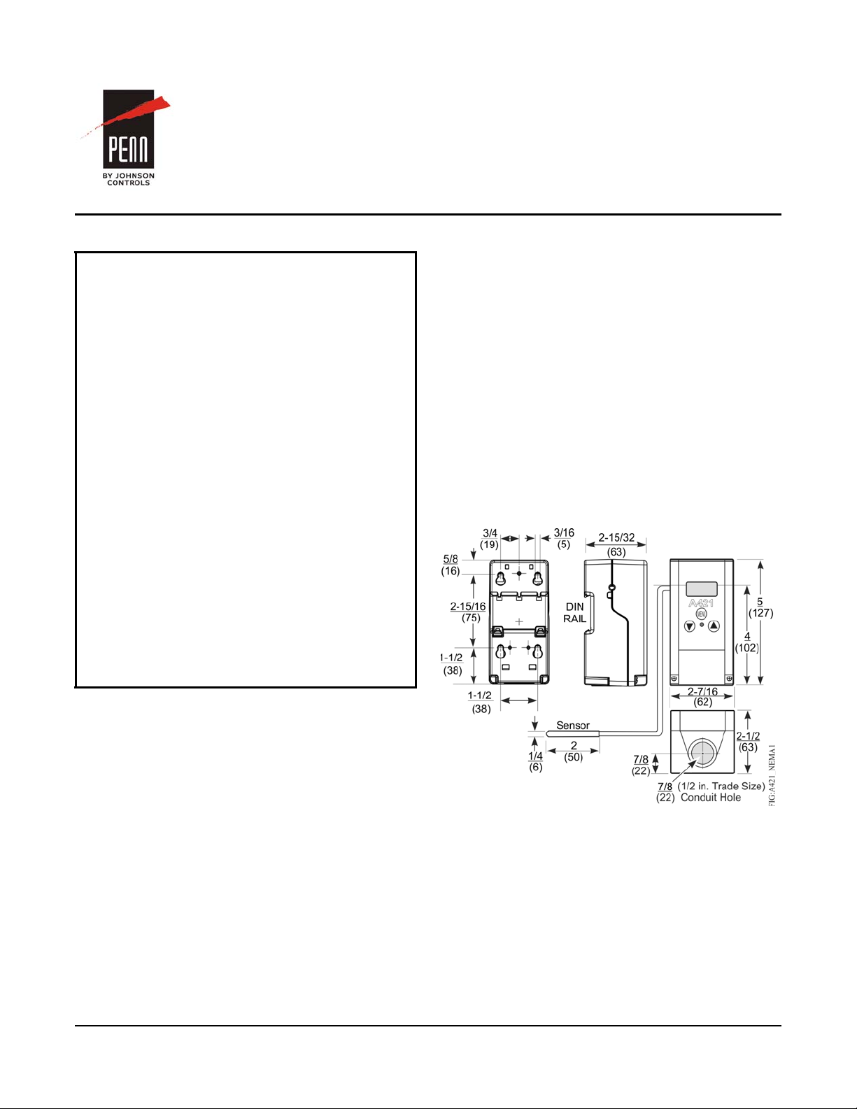
Figure 1: A421ABT Control with Type 1 (NEMA),
IP20 Enclosure; Dimensions, in. (mm)
A421 Series Electronic Temperature Controls with
Cycle Timer
Installation Instructions
A421ABT-x, A421AET-x
Refer to the QuickLIT website for the most up-to-date version of this document.
Applications
IMPORTANT: Use this A421 Series Electronic
Temperature Control only as an operating control.
Where failure or malfunction of the A421 control could
lead to personal injury or property damage to the
controlled equipment or other property, additional
precautions must be designed into the control
system. Incorporate and maintain other devices, such
as supervisory or alarm systems or safety or limit
controls, intended to warn of or protect against failure
or malfunction of the A421 control.
IMPORTANT: Utiliser ce A421 Series Electronic
Temperature Control uniquement en tant que
dispositif de régulation. Lorsqu'une défaillance ou un
dysfonctionnem ent du A421 control risqu e d e
provoquer des blessures ou d'endommager
l'équipement contrôlé ou un autre équipement, la
conception du système de contrôle doit intégrer des
dispositifs de protection supplémentaires. Veiller
dans ce cas à intégrer de façon permanente
d'autres dispositifs, tels que des systèmes de
supervision ou d'alarme, ou des dispositifs de
sécurité ou de limitation, ayant une fonction
d'avertissement ou de protection en cas de
défaillance ou de dysfonctionnement du
A421 control.
Part No. 24-7664-3043, Rev. B
Issued March 2016
A421 Control with Cycle Timer also provides sensor
offset capability and restricted user adjustment. The
temperature control range is -40 to 212°F or
-40to100°C.
The A421 controls are available either in Type 1
(NEMA), IP20 (CE), high-impact plastic enclosures
suitable for surface or DIN rail mounting (Figure 1)
or in Type 4X (NEMA), IP66 (CE) watertight, corrosion
resistant surface mount enclosures (Figure 2).
The control housing base on the Type 4X/IP66 models
can be easily rotated 180º relative to the control
housing cover and LCD, allowing you to bring the
electrical connection to either the top or bottom of the
mounted control. Do not twist the wiring harness
between the housing base and cover more than 180º.
Dimensions
The A421 Series Electronic Temperature Controls are
single-stage, electronic temperature controls with a
single-pole, double-throw (SPDT) output relay.
A421 controls feature a backlit LCD with adjustable
brightness and three-button tou ch pad interface that
can be set up to restrict user adjustments. An LED
indicates the output relay's On/Off status.
A421 Series Electronic Temperature Controls with Cycle Timer Installation Instructions
1
Page 2
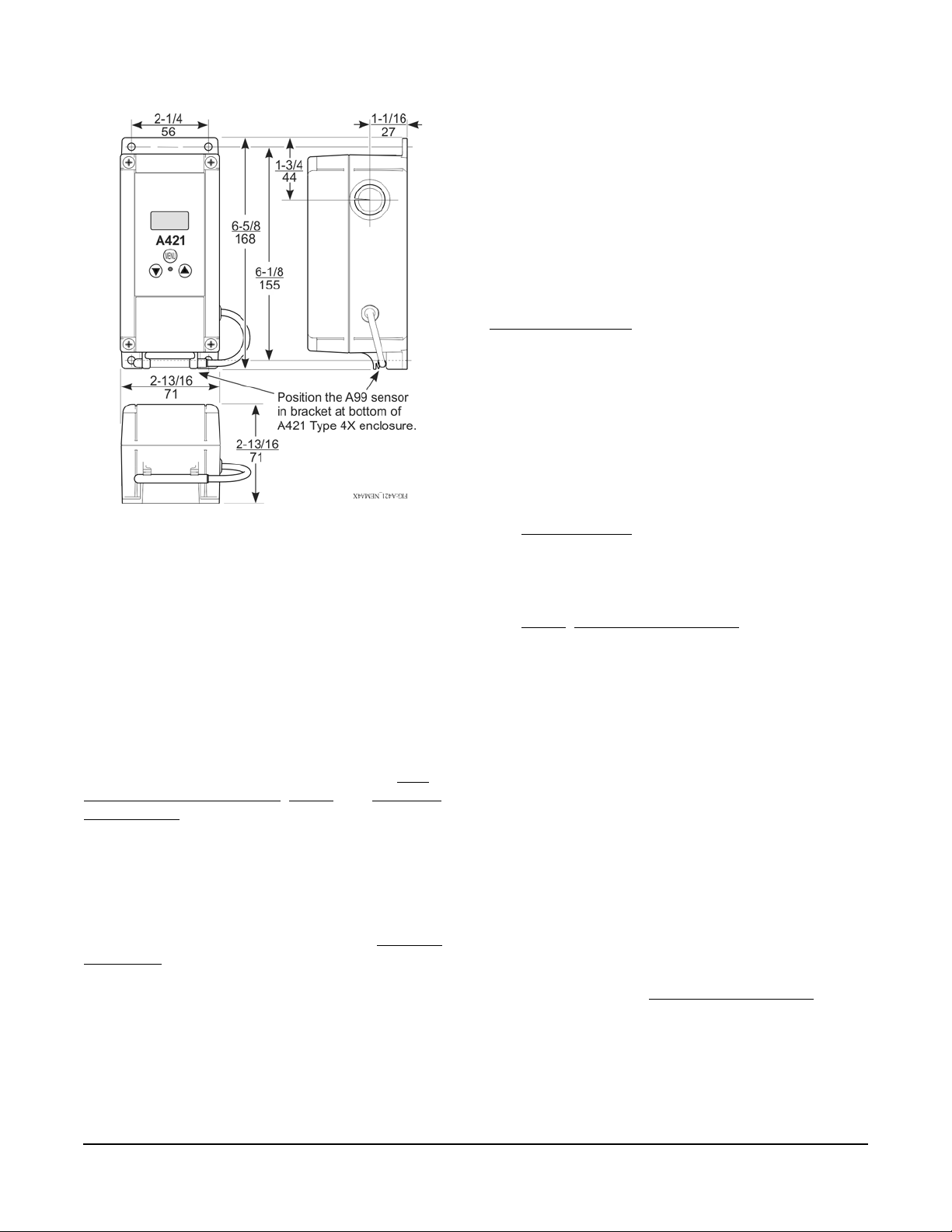
Figure 2: A421AET Control with Type 4X (NEMA),
IP66 Enclosure; Dimensions, in. (mm)
The A99 Series sensors are moisture tolerant and
splash resistant, but do not completely immerse the
A99 sensor in water or any other liquid. Immersing th e
sensor can allow liquid to enter the sensor probe where
the steel tube meets the wire cable and result in sensor
failure, which voids any warranty.
In applications where the sensor may be exposed to a
lot of moisture, splashing, or rain, we recommend
mounting the sensor in a vertical position with the cable
at the bottom routed downward to allow moisture to
drain away from the steel probe. Use a suitable bulb
well for complete fluid immersion applications. See
Ordering Information
The A99 Series sensors are positive temperature
coefficient (PTC) sensors. To test an A99 sensor,
disconnect the sensor from the control and measure
the resistance between the sensor leads.
• When the temperature at the sensor is 77°F
(25°C), the resistance should be 1,035 ohms.
• When the temperature at the sensor is 32°F (0°C),
the resistance should be 855 ohms.
for a recommended bulb well.
A421 Control with Cycle Timer
The A421 Control with Cycle Timer is a free-cooling,
duty-cycle ventilation control. This control provides
timed-ventilation and over-cooling protection.
The A421 equipped with Cycle Timer is used in
agricultural and related applications where fr ee-cooling
and ventilation can be used.
Parts Included
Each A421 Control includes a Johnson Controls/
PENN® A99 Series temperature sensor. See A99
Series Temperature Sensors, Wiring, and Technical
Specifications for more information about A99 se nsors.
A99 Series Temperature Sensors
The A421 controls require an A99 sensor, and each
A421 control includes an A99 sensor. Any A99 Series
sensor works with the A421 Series controls. Do not
replace an A99 Series sensor with any other brand,
series, or type of temperature sensor. See Ordering
Information for available A99 Series sensor models.
The sensor leads may be extended in the field. See
Table 1 for recommended wire sizes and lengths. On
long sensor cable runs, use shielded cable to reduce
Electro-Magnetic Interference (EMI). Obse rve EMI best
practices when routing sensor leads.
See Troubleshooting
When an A99 sensor is connected to a standard
A421 control, the range of usable values is restricted
by the control to -40 to 212°F or -40 to 100°C.
See Wiring
A99B Series Temperatur e Sen so rs Prod uc t/Technical
Bulletin (LIT-125186) for more information regarding
A99 Series sensors.
, Technical Specifications, and refer to the
for more information.
Mounting
Observe the following guidelines when locating and
mounting an A421 control:
• Ensure that the mounting surface can support the
control, DIN rail, mounting hardware, and any
(user-supplied) panel or enclosure.
• Mount the control in a vertical, upright orientation
wherever possible. DIN rail mounting is strongly
recommended for Type 1 controls.
• In direct-mount applications, mount the control on
a flat and even surface.
• Mount the control in a location free of corrosive
vapors and observe the ambient operating
conditions listed in Technical Specifications
both the A421 control and the A99 sensor.
• Allow sufficient space for connecting and routing
wires, viewing the LCD, and using the touchpad.
for
A421 Series Electronic Temperature Controls with Cycle Timer Installation Instructions
2
Page 3
• Do not mount the control on surfaces that are
!
prone to vibration or in a location where
high-voltage relays, motor starters, other sources
of electromagnetic emissions, or strong radio
frequency may cause interference.
On Type 4X models, select the knockout to be
removed. Place a screwdriver blade on the knockout
near the edge. Apply a sharp blow to the screwdriver
handle to loosen the knockout. Be careful not to
damage the control’s interior components.
• Do not install the control in an airtight enclosure.
• Do not install heat generating devices with the
control in an enclosure that may cause the ambient
temperature to exceed 150°F (66°C).
To mount a Type 1/IP20 control on DIN rail:
1. Provide a section of 35 mm DIN rail that is longer
than the control width, and mount the DIN rail in a
suitable location using appropriate mountin g
hardware.
2. Clip the control module on the rail, position the
module’s upper DIN rail clips on the top rail, and
gently snap the lower clips on to the bottom of the
rail.
To direct-mount a Type 1/IP20 control to a wall or
other flat surface using the four keyhole slots:
1. Remove the enclosure cover, place the control
horizontally against the wall surface in a suitable
location, and mark the keyhole slot locations on the
mounting surface.
2. Install appropriate screws or fasteners, leaving the
screw heads approximately one or two turns away
from flush to the mounting surface.
3. Position the control mounting slots over the screw
heads, and then carefully tighten the mounting
screws to secure the control to the surface.
4. When mounting the control on an uneven surface,
use shims to mount the control evenly on the
surface.
Additional Guidelines for Mounting Type 4X/IP66 Controls
The Type 4X models may be mounted to flat vertical
surfaces using the four holes at the enclosure corners.
Place the control against a flat wall surface in a suit able
location, and mark the mounting screw hole locations
on the mounting surface. Use appropriate screws and
shims to mount the control evenly on the surface.
An additional low-voltage, two-wire cable is required to
operate the A421 (optional) manual override feature.
On Type 4X/IP66 enclosures, you must install a
suitable watertight fitting in an available knockout to
pass the two-wire cable through the enclosure wall.
The control enclosure base on the Type 4X/IP66
models can be easily rotated 180º relative to the
control enclosure cover and LCD, allowing you to bring
the electrical connection to either the top or bottom of
the mounted control.
Note: Do not twist the wiring harness between the
enclosure base and cover more than 180º.
Wiring
Observe the following guidelines:
WARNING: Risk of Electric Shock.
Disconnect or isolate all power supplies
before making electrical connections.
More than one disconnection or isolation
may be required to completely
de-energize equipment. Contact with
components carrying hazardous voltage
can cause electric shock and may result
in severe personal injury or death.
AVERTISSEMENT : Risque de
décharge électrique.
Débrancher ou isoler toute alimentation
avant de réaliser un raccordement
électrique. Plusieurs isolations et
débranchements sont peut-être
nécessaires pour couper entièrement
l'alimentation de l'équipement. Tout
contact avec des composants porteurs
de tensions dangereuses risque
d'entraîner une décharge électrique et de
provoquer des blessures graves, voire
mortelles.
IMPORTANT: Use copper conductors only. Make
all wiring in accordance with local, national, and
regional regulations.
IMPORTANT: Do not exceed the A421 control’s
electrical ratings. Exceeding the electrical ratings
can result in permanent damage to the control and
void any warranty.
A421 Series Electronic Temperature Controls with Cycle Timer Installation Instructions
3
Page 4
IMPORTANT: Run all low-voltage wiring and
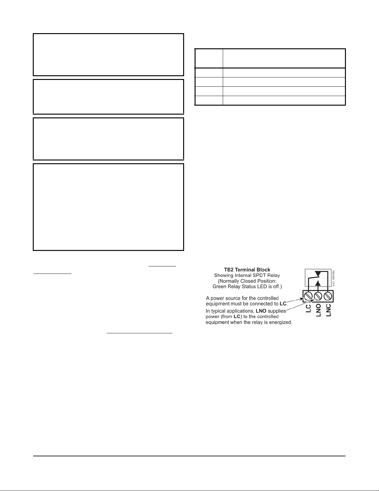
Figure 3: TB2 Terminal Block Showing
Connections to the Internal SPDT Relay
cables separate from all high-voltage wiring .
Shielded cable is strongly recommended for input
(sensor) cables that are exposed to high
electromagnetic or radio frequency noise.
IMPORTANT: Electrostatic discharge can damage
A421 controls. Use proper Electrostatic Discharge
(ESD) precautions during installation and servicing
to avoid damaging A421 controls.
IMPORTANT: Do not connect supply power to the
A421 controls before checking all wire connections.
Short circuits or improperly connected wires can
result in damage to the modules and void any
warranty.
IMPORTANT: When connecting an A99 sensor
with a shielded cable to an A421 Control, connect
the cable shield drain lead to the COM (common)
terminal on the sensor and binary input terminal
block (TB3). Do not connect the shield at any other
point along the cable, and isolate and insulate the
shield along the entire length of the sensor cable.
Connecting a cable shield at more than one point
can enable transient currents to flow through the
sensor cable shield, which can cause erratic control
operation.
Observe the wire size restrictions listed in Table 2 on
page 5 and the Electrical Ratings listed in Technical
Specifications on page 15.
Table 1: Maximum Recommended Sensor Cable
Lengths and Wire Sizes
Wire
Gauge
16 AWG 500 (150)
18 AWG 300 (100)
20 AWG 200 (60)
22 AWG 125 (40)
1. At the listed maximum cable lengths, there is less than
1Fº (0.6Cº) error between the temperature sensed at the
A99 sensor and the temperature displayed on the LCD.
Maximum Sensor Cable Length
Feet (Meters)
1
,
TB2 Terminal Block and SPDT Relay Output
The terminals (LC, LNO, and LNC) on the TB2 terminal
block are connected to a SPDT dry-contact relay in the
A421 control (Figure 3). The control does not provide
any internal power to the TB2 terminals or relay
contacts. The A421 control simply energizes and
de-energizes the relay to open and close the contacts
based on the On/Off temperature values.
Relay De-energized (Off) = LC open to LNO (as
shown in Figure 3) and the relay status LED is off
Relay Energized (On) = LC closed to LNO and the
relay status LED is on
Figure 4 shows how to wire the A421 control to use the
same power source that powers the controlled
equipment to also power the A421 control.
Observe the following guidelines, procedures, and
illustrations when wiring an A421 Series control and
A99 Series sensor.
• Select only the A99 sensors that are designed to
operate in the ambient operating range that your
A421 control is intended to monitor and control as
shown in Table 6. See Technical Specifications
for
more information.
• Keep the sensor leads as short as possible in your
application. The additional resistance in long
sensor cables creates an offset between the actual
temperature and the displayed temperature. See
Table 1 when extending sensor leads.
• A99 sensors are not polarity specific. Either lead
can be connected to the SEN or COM terminals.
• We recommend 22 AWG, stranded, twisted-pair
cable with a shield for extending sensor cable runs.
You can also provide an independent power source for
the A421 control on the TB1 terminals and then wire
the TB2 relay terminals to a separate power source for
switching and powering the controlled equipment
circuit.
A421 Series Electronic Temperature Controls with Cycle Timer Installation Instructions
4
Page 5
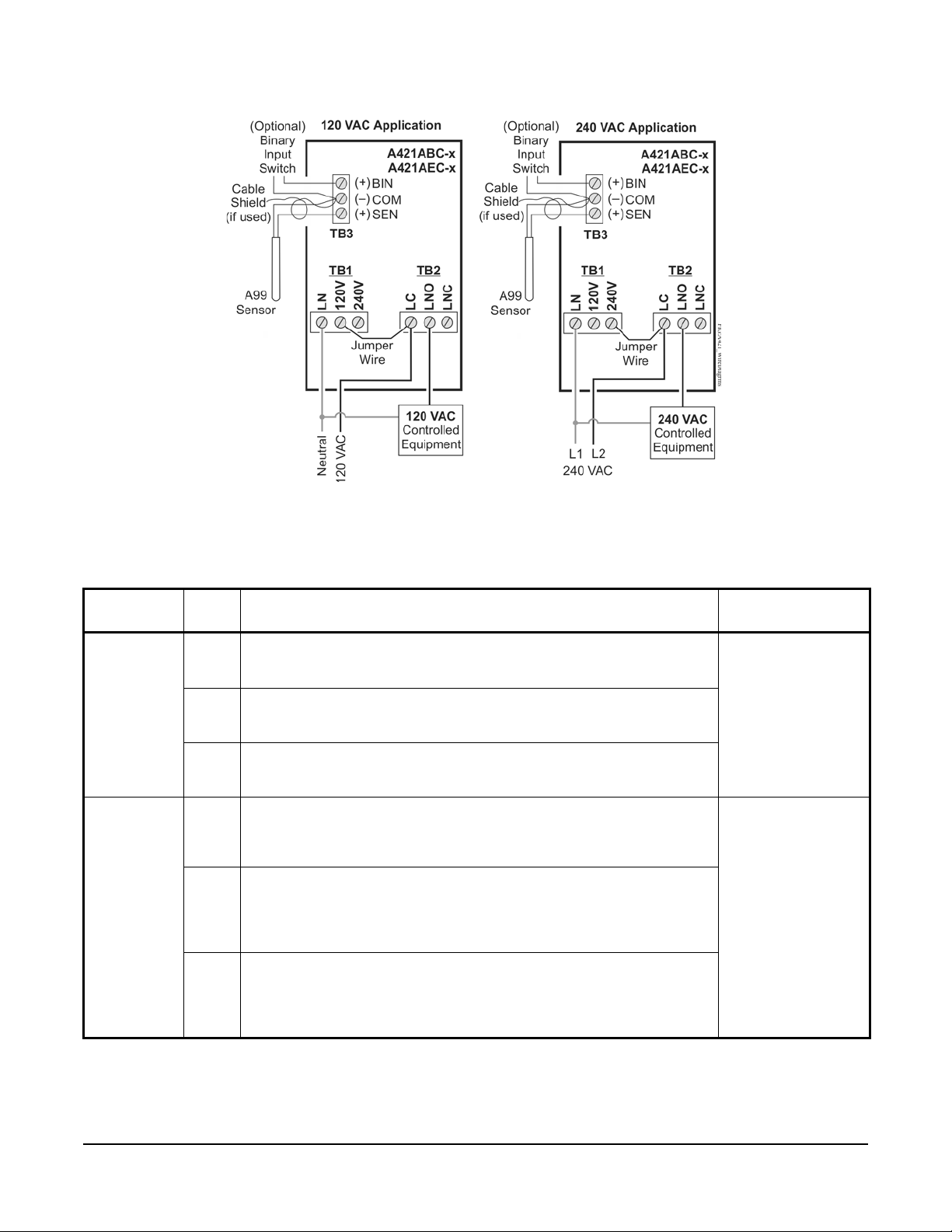
Figure 4: Wiring the A421 Series Controls Using the Same Power Source
to Power the Control Operation and Power the Controlled Equipment
Table 2: A421 Control Wiring Terminals and Wi re Size Information (Part 1 of 2)
Terminal
Label Description, Function, and Requirements Recommended
Block
TB1
120/240 VAC
Models
TB2 LC Line-Voltage SPDT Relay Common Contact: Connect power supply to
LN Line-Voltage Power So urce (Common): Connect the neutral wire for
120 VAC supply power applications. Connect the L1 supply power lead for
all 208/240 VAC supply power applications.
120V Line-V olt age 120 VAC Control Power (Hot): Connect the 120 VAC supply
power (hot) for 120 VAC supply power applications (using jumper from LC
in Figure 4).
240V Line-Voltage 240 VAC Control Power (L2) Terminal: Connect the L2
supply power connection for 208/240 VAC supply power applications
(using jumper from LC in Figure 4).
power the controlled load.
Connect 120 VAC (hot) for 120 VAC applications.
Connect L2 for 208/240 VAC applications.
LNO Line-Voltage SPDT Relay Normally Open Contact: Connects controlled
equipment to the Line-Voltage Normally Open (LNO) contact on the SPDT
relay. When LC is closed to LNO, the relay is energized and the green LED
is on. The LNO terminal typically provides power to the controlled
equipment in both cooling and heating applications.
LNC Line-Voltage SPDT Relay Normally Closed Contact: Connects
controlled equipment to the Line-Voltage Normally Closed (LNC) contact
on the SPDT relay. When LC is closed to LNC, the relay is de-energized
and the green LED is off. The LNC terminal is not typically wired to the
controlled equipment.
Wire Sizes
28 AWG to 12 AWG
0.08 mm2 to 4.0 mm
28 AWG to 12 AWG
0.08 mm
2
to 4.0 mm
2
2
A421 Series Electronic Temperature Controls with Cycle Timer Installation Instructions
5
Page 6
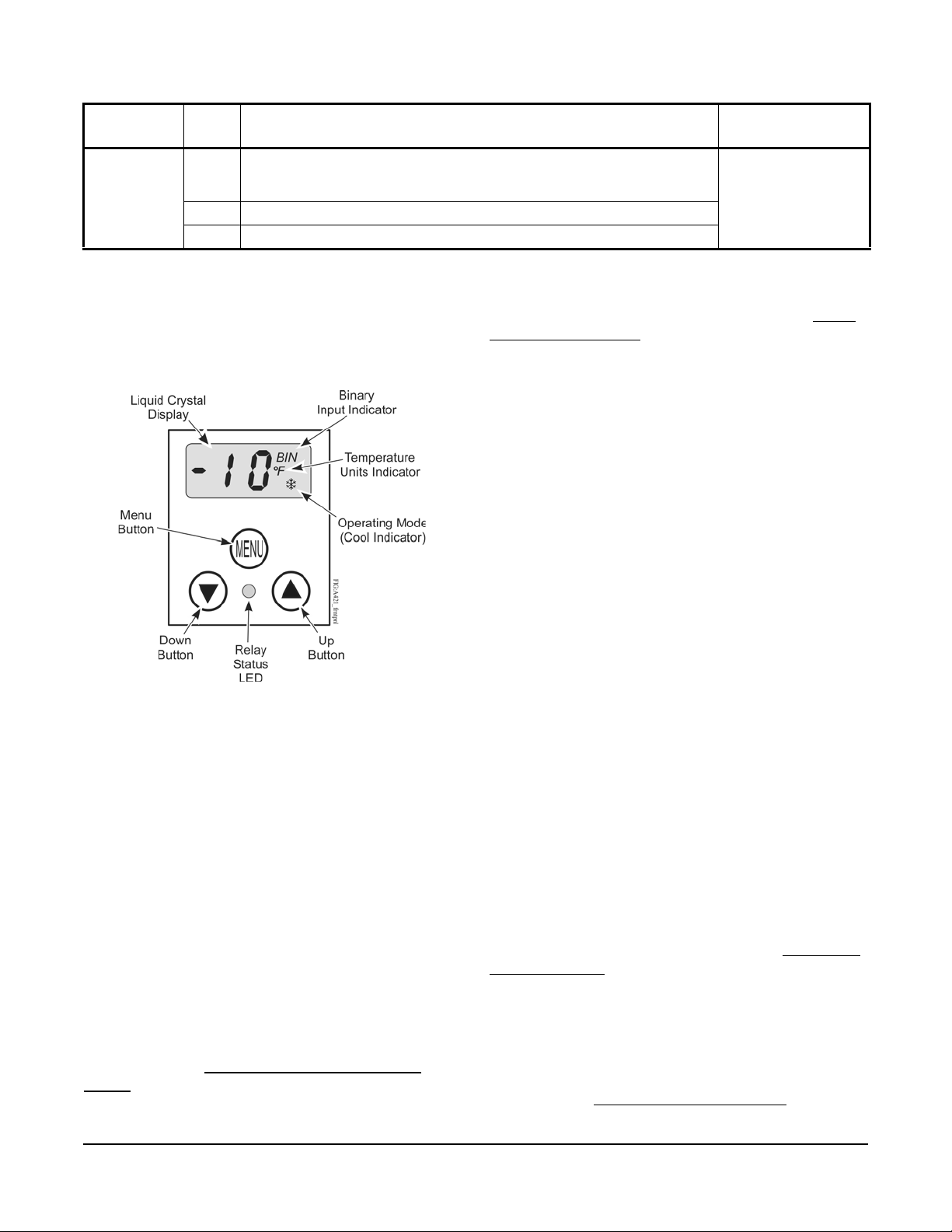
Table 2: A421 Control Wiring Terminals and Wi re Size Information (Part 2 of 2)
Figure 5: A421 Control Front Panel with LCD
and Three-Button User Interface
Terminal
Label Description, Function, and Requirements Recommended
Block
TB3 BIN Detects a switch closure between the BIN and COM terminals and
overrides the control to turn the fan on. Normal control resumes after this
switch is opened again.
COM Connects low-voltage common from the sensor and binary input.
SEN Connects low-voltage input signal wire from control sensors.
Wire Sizes
22 AWG (0.34 mm
stranded, shielded
cable recommended
2
)
Setup and Adjustments
Front Panel
The front panel of the A421 Series Electronic
Temperature Control has a simple LCD and a
three-button user interface (Figure 5).
Three-Button Touchpad
The touchpad has three buttons for setup and
adjustment of the A421 control (Figure 5). See Menu
Navigation Guidelines on page 8 for more information
on using the three-button touchpad.
Relay Status LED
The green LED on the front panel illuminates when the
SPDT output relay is energized and the LC and LNO
contacts are closed. See Figure 5.
Parameter Codes and Modes of Operation
Relay Off Temperature (OFF): Select the temperature
at which the output relay de-energizes, the LC to LNO
relay contacts open (cutout), and the green LED goes
off. The range of usable temperature values is
-40 to 212°F or -40 to 100°C in 1° increments.
Relay On Temperature (On): Select the temperature
at which the output relay energizes, the LC to LNO
relay contacts close (cut in), and the green LED lights.
The range of usable temperature values is
-40 to 212°F or -40 to 100°C in 1° increments.
The A421 Series Control with Cycle Timer functions in
Cooling Mode only.
Liquid Crystal Display
The A421 Series Control has a backlit LCD screen
(Figure 5). The LCD brightness is adjustable. During
normal operation, the LCD displays the Main screen,
which provides following information:
• the temperature sensed at the A99 sensor
• the selected temperature units (°F or °C)
• the mode of operation (snowflake = cooling mode
only)
• Binary Input status (BIN) when a (user-supplied)
toggle switch is connected and closed to manually
override the relay control.
During setup and adjustment, the LCD displays the
parameter code screens and the parameter value
screens. See the A421 Control Parameter Setup
Menus on page 8 for more information.
A421 Series Electronic Temperature Controls with Cycle Timer Installation Instructions
Temperature Units (Un): Select the desired
temperature scale for your application. Select either the
Fahrenheit (°F) or Celsius (°C) temperature scale.
Note: After changing the value for the temperature
units (Un), confirm that the temperature values for the
other parameter codes are still correct for your
application.
Low Temperature Stop (LtS): Select the lowest
temperature value below which the Low Temperature
On-Time (Ltt) is enforced. This parameter is also used
when control adjustment is restricted. See Restricting
User Adjustment.
The range of usable temperature values is -40 to 212°F
or -40 to 100°C in 1° increments.
High Temperature Stop (HtS): Select the highest
temperature value in which the On/OFF control band
can be adjusted when the control adjustment is
restricted. See Restricting User Adjustment
.
6
Page 7
The range of usable temperature values is -40 to
212°F or -40 to 100°C in 1° increments.
Restricted Adjustment Mode: The HtS and LtS
values define the restricted adjustment temperature
range and are enforced only when the A421 control is
set to the restricted adjustment mode (Figure 9). See
Restricting User Adjustment
.
Low T emper ature On-Time (Ltt): Select the minimum
relay On-time whenever the sensed temperature is less
than the LtS. The range of values are zero (0) to 300
seconds.
The purpose of this parameter is to prevent overcooling that could occur if a long Ont is used when the
outside air is very cold.
Sensor Offset Adjustment (So): Sensor offset allows
you to compensate for any difference between the
displayed temperature value and the temperature
sensed at the A99 sensor. Select a temperature value
to offset the temperature displayed on the LCD from
the temperature sensed at the sensor. The sensor
offset adjustment range is from -5 to 5°F or -3 to 3°C in
1° increments.
Sensor Failure Mode (SF): Select how the control’s
fan relay operates (energized or de-energized) in the
event of a sensor or sensor wiring failure. When the
control detects a sensor circuit failure, the fan relay
operates in the selected sensor failure mode. The LCD
flashes SF and OP if the sensor circuit is open or SF
and SH if the sensor circuit is shorted.
Note: If LtS is left at the default value (40°F), the Ltt
parameter has little or no impact.
Minimum Relay On-Time (Ont): Select the minimum
relay On-time per cycle period (cP). Ont is used when
the sensed temperature is greater that the LtS. The
range of values are zero (0) to 300 seconds.
During any relay On-time (Ont or Ltt), Ont is displayed
followed by the remaining Ont seconds and the sense d
temperature in sequence. This sequence of three
screens continues until the Ont seconds expire for the
cP.
When the fan relay is On for a temperature
(free-cooling) ventilation cycle, the screen displays the
sensed temperature and a snowflake in the lower-right
corner of the screen to indicate the fan relay is On for
free-cooling.
Cycle Period (cP): Select the Cycle Period for
free-cooling and ventilation control. The range of
values are zero (0) to 60 minutes.
Backlight Brightness Level (bll): The backlight
brightness level feature allows you to adjust the LCD
backlight intensity. At level 0 the backlight is off. Level
10 is the brightest backlight setting and the system
default. The selected backlight brightness level is
applied to the LCD during normal operation. When you
enter the programming menus to set up the control or
press any key, the LCD automatically goes to the
brightest level. If no key is pressed for 30 seco nd s, th e
main screen is displayed and the backlight setting
returns to the selected brightness level.
Switch-Activated Override (Ord): When a switch is
closed between BIN and COM terminals of TB3, the
control is overridden, and the fan relay re mains on. The
fan relay remains On until the circuit (toggle switch)
between BIN and COM is open.
The relay remains energized regardless of the sensor
value, sensor fail state, or any timing parameters (cP,
Ont, Ltt). The control display alternates between the
main display and manual override (Ord).
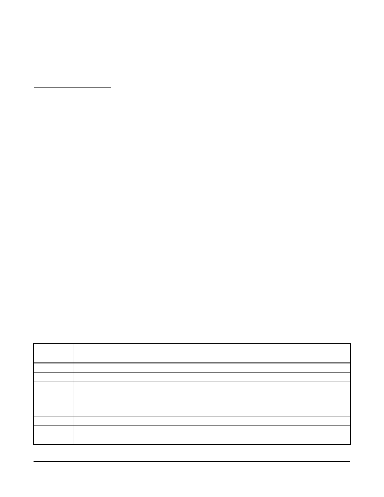
Table 3: Standard Parameter Setup Codes, Descriptions, Range of Values, and Default Values
(Part 1 of 2)
Parameter
Code
Un Temperature Units (Advanced only) ºF or ºC ºF
LtS Low Temperature Stop (Advanced only) -40 to 212ºF (-40 to 100ºC) 40ºF
HtS High Temperature Stop (Advanced only) -40 to 212ºF (-40 to 100ºC) 212ºF
OFF Relay Off Temperature (Basic, Advanced, and
On Relay On Temperature (Basic and Advanced) -40 to 212ºF (-40 to 100ºC) 75ºF
Ltt Low Temperature On-Time (Advanced only) 0 to 300 (seconds) 60 (seconds)
Ont Minimum Relay On-Time (Advanced only) 0 to 300 (seconds) 60 (seconds)
cP Cycle Period 0 to 60 (minutes) 10 (minutes)
Parameter Description (Menu) Range of Usable Values Factory Default
1
Value
-40 to 212ºF (-40 to 100ºC) 70ºF
Restricted)
A421 Series Electronic Temperature Controls with Cycle Timer Installation Instructions
7
Page 8
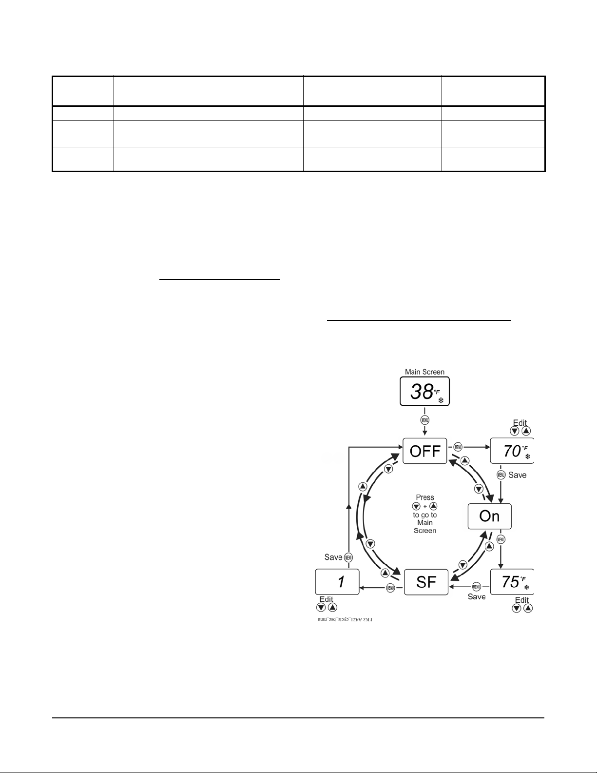
Table 3: Standard Parameter Setup Codes, Descriptions, Range of Values, and Default Values
Figure 6: Navigating the Basic Menu
(Part 2 of 2)
Parameter
Code
So Sensor Offset Adjustment (Advanced) -5 to 5ºF (-3 to 3ºC) 0ºF
SF Sensor Failure Action (Ba sic and Advanced) 0 = output relay de-energized
bll LCD Backlight Brightness Level Adjustment
1
The default values for general application models are shown. OEM models may have different default values.
Parameter Description (Menu) Range of Usable Values Factory Default
1
Value
1 (output relay
energized)
10 (brightest backlight)
(Advanced only)
1 = output relay energized
0 to 10; 0 = backlight off, 10 =
brightest backlight setting
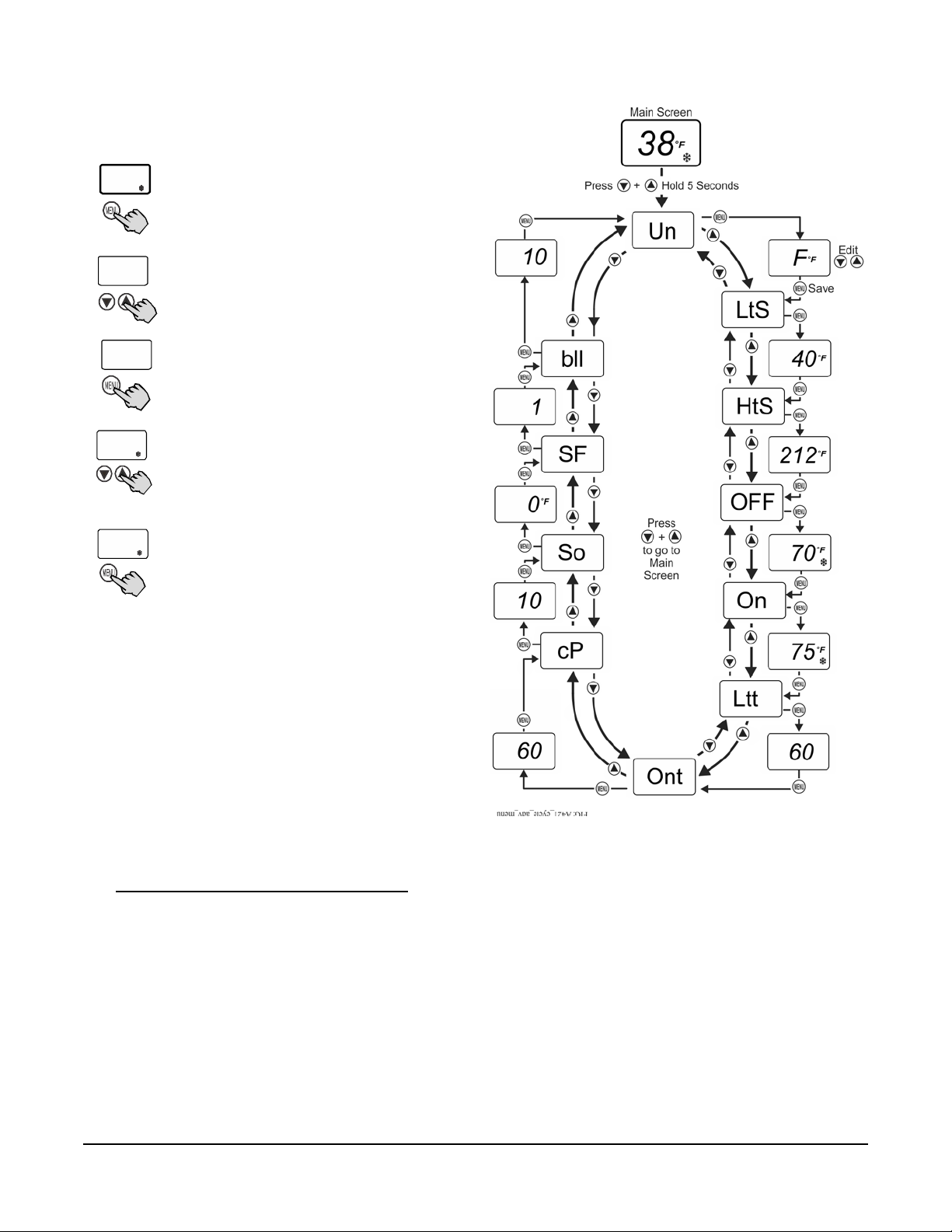
A421 Control Parameter Setup Menus
The A421 temperature controls have a Basic and
Advanced setup menu that allow you to scroll through
the parameter setup codes, view and edit parameter
values, and set up your control for your application
requirement. The control also has a Restricted
(adjustment) menu. See Restricting User Adjustment
for more information.
Note: The A421 control retains a copy of the saved
parameter values in memory. When you change and
save a new value, the new value immediately
overwrites the previous value and is saved to memory.
In the event of a power failure, brown out, or when you
disconnect power from the control, all of the current
parameter values in memory are retained.
Reconnecting power to the control resto r es all of the
saved values.
Menu Navigation Guidelines
The A421 control buttons and display operate the
same in the Basic and Advanced menus. While in any
parameter code screen, the following behavior is
observed:
• The parameter code flashes on and off.
Note: If you do not press MENU to save a new value,
the control reverts to the last saved value.
After 30 seconds of ina ctivity, while in any screen, the
control reverts to the Main screen.
Basic Menu The Basic menu allows you to quickly edit the On and
OFF temperature values, and the Sensor Failure Mode
(SF).
See Parameter Codes and Modes of Operation
and
Table 3 for more information regarding parameter
codes, usable parameter values, and default values.
• Press or to navigate through all of the
parameter code screens.
• To exit either menu and return to the Main screen,
press and simultaneously.
While in any parameter value screen, the following
behavior is observed:
• The parameter value flashes on and off.
• Press or to scroll through all of the available
parameter values for the associated parameter
code.
• With the preferred parameter value displayed,
press MENU to save the value and go to the next
parameter code screen.
A421 Series Electronic Temperature Controls with Cycle Timer Installation Instructions
8
Page 9
Viewing and Changing Values in the Basic Menu
38
o
F
On
25
o
F
35
o
F
Figure 7: Navigating the Advanced Menu
To access the Basic menu and view and change the
Basic parameter values, follow these steps:
1. With the Main screen displayed,
press MENU. The LCD displays OFF,
which is the first parameter code
screen displayed in the Basic menu.
2. Press or to scroll through all of
OFF
the Basic parameter codes and
display the preferred code.
3. With the preferred parameter code
displayed, press MENU to display the
current parameter value for the code.
4. With the current parameter value
displayed, press or to scroll
through all of the parameter’s usable
values and display the preferred
value.
5. With the preferred parameter value
displayed, press MENU to save the
displayed value and go to the next
parameter code.
To exit the Basic menu and go directly into the
Advanced menu, simultaneously press and , and
hold them for 5 seconds.
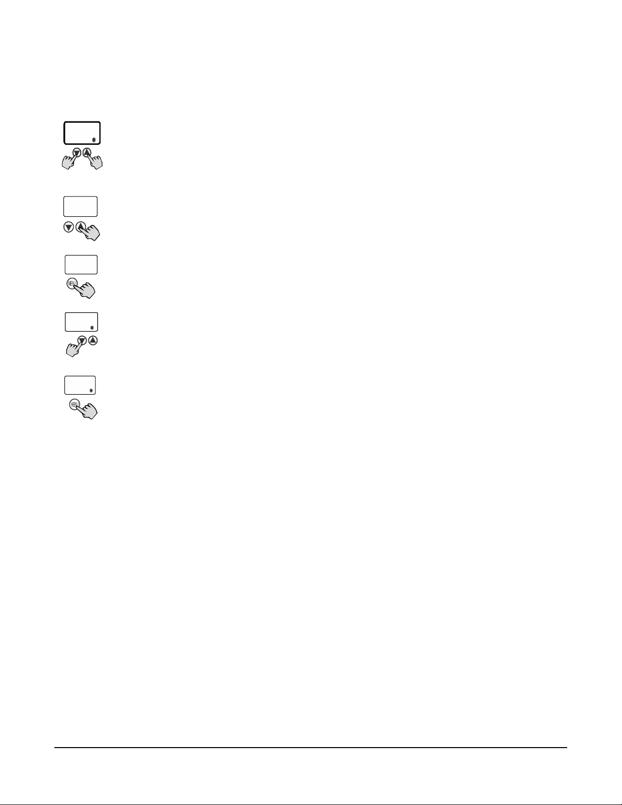
Advanced Menu
The Advanced menu allows you to change the
parameter values in the Basic menu and the values for
the Advanced parameter codes; including Temperatur e
Units (Un), Low Temperature St op (LtS), High
Temperature Stop (HtS), Low Temperature On-Time
(Ltt), Minimum Relay On-Time (Ont), Cycle Period
(cP), Sensor Offset Adjustment (So), Sensor Failure
Option (SF), and Backlight Brightness Level (bll).
See Parameter Codes and Modes of Operation
and
Table 3 for more information regarding parameter
codes, usable parameter values, and default values.
A421 Series Electronic Temperature Controls with Cycle Timer Installation Instructions
9
Page 10
Viewing and Changing Values in the Advanced
38
o
F
Un
o
F
75
o
F
Menu
To access the Advanced menu and view and change
the parameter values, follow these steps:
1. With the Main screen displayed,
press and hold and
simultaneously for 5 seconds. The
LCD displays Un, which is the first
parameter code screen displayed in
the Advanced menu.
2. Press or to scroll through all of
the Advanced parameter codes and
display the preferred code.
3. With the preferred parameter code
HtS
displayed, press MENU to display the
current parameter value for the code.
4. With the current parameter value
212
displayed, press or to scroll
through all of the parameter code’s
usable values and display the
preferred value.
5. With the preferred parameter value
displayed, press MENU to save the
displayed value and go to the next
parameter code.
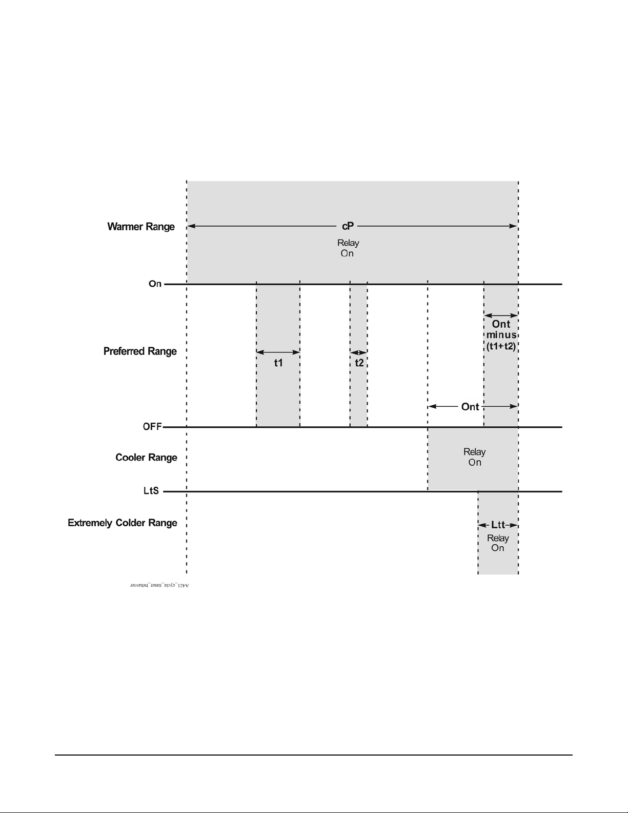
A421 Series Control with Free-Cooling Ventilation
Control Behavior for Warmer than Preferred Temperature
When the sensed temperature is warmer than the On
value, the relay remains On. See Figure 8.
Control Behavior for Preferred Temperature Range
When the sensed temperature is in between the On
and OFF values, the following behavior is enforced:
• The fan relay is On for at least the Minimum Relay
On-Time (Ont) during a Cycle Period (cP). See
Figure 8.
• The fan relay goes Off when the sensed
temperature is less than or equal to the OFF value.
• If the temperature based On-time (t1+t2) is less
than Ont, only the remaining Ont [Ont minus
(t1+t2)] is enforced at the end of the cP.
• The total On-time may exceed the Ont only when
the sensed temperature On-time (t1+t2) is greater
than Ont.
• If the fan relay is On due to the sensed
temperature for a time is greater than or equal to
Ont (earlier in the cP), then the fan relay remains
OFF for the remainder of the cP.
• The only condition that turns the fan relay On
greater than the Ont is when the sensed
temperature rises to the On value.
Control Behavior for Cooler than Preferred Temperature Range
The fan relay is On for at least the Ont (Minimum Relay
On-Time) during ea ch Cycle Period (cP). See Figur e 8.
Control Behavior for Extremely Colder than Preferred Temperature Range
When the sensed temperature is less than or equal to
the Low Temperature Stop (LtS) value, the relay is On
for the Low Temperature On-Time (Ltt) each Cycle
Period (cP). The following behavior is enforced:
• The On-time is restricted to just the Ltt value
whenever the sensed temperature falls below the
LtS value. See Figure 8.
• The Ltt is the minimum time required to ventilate
the controlled space.
Setting Up the Control for Free-Cooling and Ventiliation
1. Select the Low Temperature Stop (LtS). The LtS
value must be less than or equal to the OFF value
enforced at setup. See Figure 8.
2. Select the Relay Off Temperature (OFF).
3. Select the Relay On Temperature (On). The On
value must be greater than the OFF value. If you
force the OFF value above the selected On value,
the On value is adjusted to remain greater than the
OFF value.
A421 Series Electronic Temperature Controls with Cycle Timer Installation Instructions
10
Page 11
4. Select the Minimum Relay On-time (Ont) per cycle
Figure 8: Cycle Timer Behavior for Free-Cooling and Ventilation Control
period (cP) when the sensed temperature remains
greater than LtS.
5. Select the Low T emperature On-Time (Ltt). The Ltt
value must be always less than or equal to the Ont.
If you force the Ltt above the Ont value, the Ont
value is adjusted to remain equal to the Ltt.
Adjusting the Ont value down is limited by the Ltt
setting.
Note: The Ltt parameter is enforced (and the Ont is
ignored) whenever the sensed temperature falls below
the LtS value (even momentarily) during a given cycle
period.
6. Select the Cycle Period (cP) for free-cooling and
ventilation control.
A421 Series Electronic Temperature Controls with Cycle Timer Installation Instructions
11
Page 12
Restricting User Adjustment
Figure 9: Adjustment Behavior in
Restricted Adjustment Mode
Figure 10: Repositioning the Jumper to
Restrict Control Adjustment
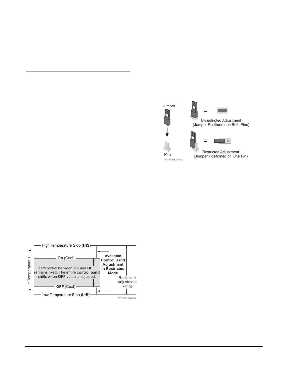
You can restrict user adjustment of the A421 control to
either just OFF value (control band) adjustment within
a defined range (Figure 9) or no user adjustment at all.
You set the A421 control into the restricted adjustment
mode by positioning the P1 jumper located on the
circuit board next to the TB3 terminal block. See
Setting the Control to Restricted Adjustment Mode
Note: Setting the A421 control up in the Restricted
Mode prevents casual users from over-adjusting the
control in your application, or from inadvertently
changing the mode of operation from cooling to heatin g
or heating to cooling (by over-adjusting the On value or
OFF value).
When the A421 control is set up in the restricted
adjustment mode, the following behavior is enforced:
• The restricted temperature adjustment range is
defined by the selected High Temperature Stop
(HtS) and Low Temperature Stop (LtS) values.
• The control band (differential) is defined by the On
and OFF values, and the control b and between On
and OFF remains fixed (not adjustable).
.
Setting the Control to Restricted Adjustment Mode
To set up the restricted adjustment feature:
1. Ensure that the A421 is not in the restricted mode
(the jumper is positioned on both pins). See
Figure 10.
2. Select the OFF and On values that define the
application’s required control band (Figure 9).
3. Change the HtS and LtS temperature values to
define the restricted adjustment range (Figure 9).
4. Disconnect power to the control and reposition the
jumper to one pin (Figure 10). Reconnect power.
• Only the OFF value can be adjusted, the control
band remains fixed, and the On value
automatically shifts equal to the OFF value
adjustment.
•The OFF value can only be adjusted to values that
maintain the entire control band within the
restricted temperature adjustment range defined
by HtS and LtS. See Figure 9.
• The basic and advanced menus are not available.
Only the restricted adjustment mode menu is
available and only the OFF value can be adjusted.
See Figure 11.
Control adjustment is now restricted to changing only
the OFF value, which shifts the On/OFF control band
within the restricted adjustment range defined by HtS
and LtS (Figure 9).
Note: To completely restrict (and lockout) all user
adjustment on the control, set the HtS value equal to
the On or OFF value and the LtS value equal to OFF or
On value. Then the (On to OFF) control band is equal
to the restricted adjustment range (LtS to HtS) and the
OFF value cannot be adjusted in the restricted mode.
Adjusting the Control In Restricted Mode
To adjust the OFF value (and shift the On/OFF control
band) within the restricted adjustment range, when the
control is in the restricted adjustment mode:
1. In the Main Screen, press MENU to go to the
restricted adjustment mode menu and display the
OFF parameter code screen (Figure 11).
2. Press MENU again to go to the OFF value screen.
3. In the OFF value screen, press or to change
the OFF value (only within the restricted
adjustment range).
4. Press MENU
return to the OFF code screen.
to save the selected OFF value and
A421 Series Electronic Temperature Controls with Cycle Timer Installation Instructions
12
Page 13
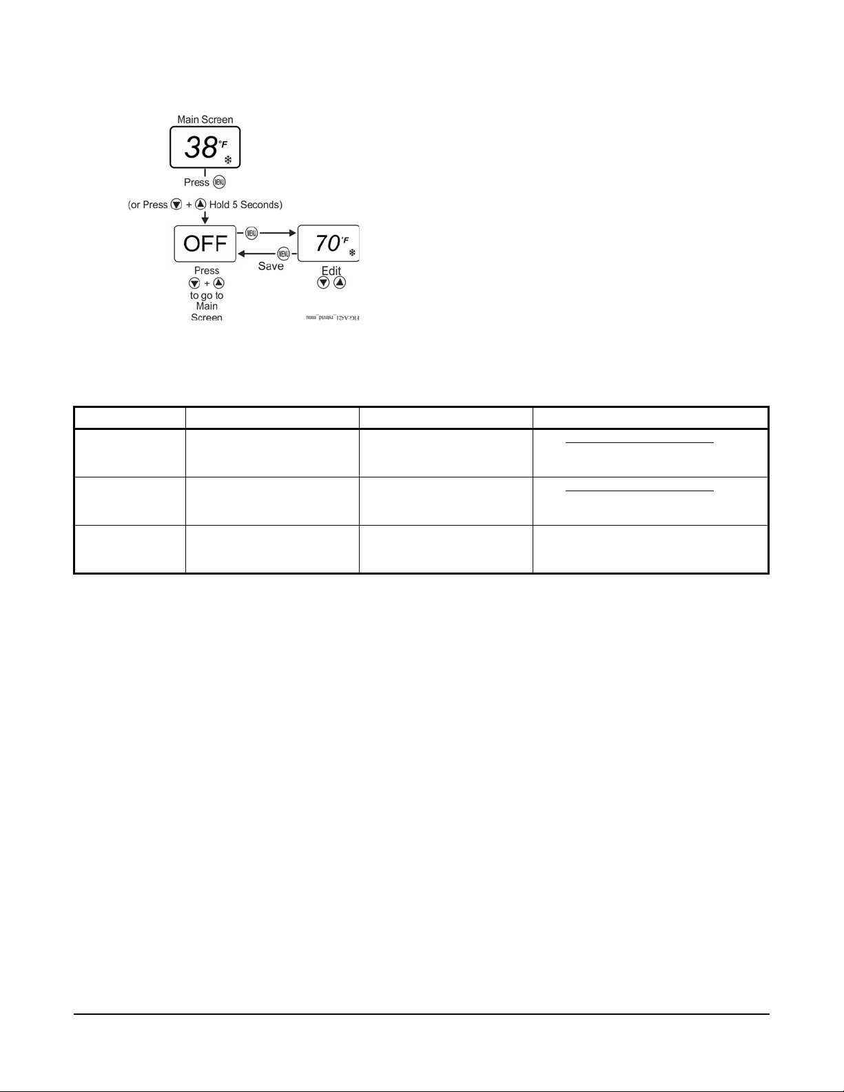
5. Press and simultaneously to return to the
Figure 11: Adjusting Temperature in the
Restricted Menu
Main screen.
T roubleshooting
Fault Codes
A421 Series controls display fault codes on the LCD as
described in Table 4.
Table 4: Fault Codes Defined
Fault Code Definition System Status Solution
SF flashing
alternately with
OP
SF flashing
alternately with
SH
EE Program failure Output is off Reset control by pressing the MENU
Open temperature sensor or
sensor wiring
Shorted temperature sensor
or sensor wiring
Output functions according
to the selected sensor failure
mode (SF)
Output functions according
to the selected sensor failure
mode (SF)
See Troubleshooting Procedure. Cycle
power to reset the control.
See Troubleshooting Procedure
power to reset the control.
button. If problems persist, replace the
control.
. Cycle
T roubleshooting Procedure
1. Check for proper voltage to the A421 control.
a. Remove the cover by loosening the two
captive cover screws.
b. Use an AC voltmeter to check the voltage
between the COM and 120V or 240V terminals
on line-voltage models. See Figure 4.
c. The voltage must be between:
• 102 and 132 VAC for 120 VAC applications
• 177 and 264 VAC for 208/240 VAC
applications
d. If the voltage reading is not within the required
range, check the power source and input
power wires for problems.
2. Check for proper sensor operation.
a. Disconnect all power sources to control.
b. Using an accurate thermometer, take a
temperature reading at the sensor location.
c. Disconnect the sensor from the control.
d. Using an ohmmeter, measure the resistance
across the two sensor leads while the sensor is
at the temperature taken in Step 2b.
e. Consult Figure 12 to verify that the measured
temperature and resistance conform to
established temperature and resistance
values.
f. If the measured values conform to the values
in Figure 12, proceed to Step 3.
g. If the sensor’s measured resistance value is
substantially different from the expected value
for that temperature, check the sensor wiring. If
sensor wiring is correct, replace the sensor.
A421 Series Electronic Temperature Controls with Cycle Timer Installation Instructions
13
Page 14
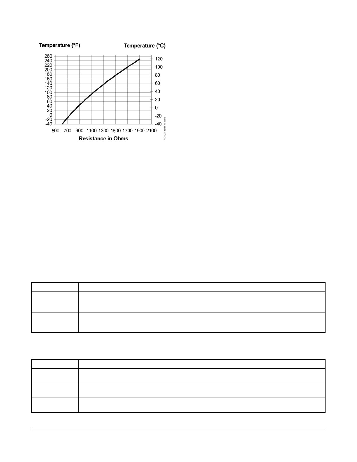
3. Check the A421 for proper operation.
Figure 12: Temperature versus Sensor
Resistance
Note: Perform Troubleshooting Steps 1 and 2 before
performing this step.
a. Disconnect the load from the output relay
terminals.
b. Ensure that the Parameter Adjustments jum per
is installed, so that access to adjust
parameters is unrestricted.
c. Reconnect the sensor leads and supply power
to the control.
d. Replace the cover.
e. Check the control settings for proper values.
f. Press MENU until On appears. Press MENU
again to display the On value.
g. Press or to change the On temperature
above and below the sensor temperature until
the relay energizes and de-energizes.
h. If the output relay does not perform as
expected, replace the A421 control.
i. If proper operation of the A421 control is
verified, reconnect the load and consult the
equipment manufacturer’s instructions for
troubleshooting the controlled equipment.
Repair Information
Do not attempt to repair or recalibrate the A421
temperature control. In case of a defective or
improperly functioning control, contact your nearest
Authorized Johnson Controls/PENN Distributor or
Sales Representative.
When contacting your Johnson Controls/PENN
Distributor, have the model number of the control
available. This number can be found on the label inside
the cover of the control.
Ordering Information
See T able 5 to order a standard A421 Series Electronic
Temperature Control. See Table 6 and Table 7 to order
A99 sensors, mounting hardware, and other
accessories used to install A421 controls. Contact your
nearest Johnson Controls/PENN distributor or sales
representative to order these products.
Table 5: A421 Series Electronic Temperature Controls with Cycle Timer Selection Chart
Product Type Description
A421ABT-02C Line-Voltage Type 1 Electronic Temperature Control with Cycle Timer: Type 1 (NEMA), IP20
A421AET-01C Line-Voltage Type 4X Electronic Temperature Control with Cycle Timer: Type 4X (NEMA), IP66
standard enclosure for DIN rail and surface-mount applications. Rated for 120/240 VAC. Includes timer
for On/Off duty-cycle control. Includes an A99BB-200C temperature sensor with 6.6 ft (2.0 m) cable.
watertight enclosure for surface-mount applications. Rated for 120/240 VAC. Includes timer for On/Off
duty-cycle control. Includes an A99BB-25C temperature sensor with 9-7/8 in. (0.25 m) cable.
Table 6: A99 Temperature Sensors Selection Chart1 (Part 1 of 2)
Product Code Description
A99BA-200C PTC Temperature Sensor: Standard probe 2 in. (5.1 cm) with 6.6 ft (2.0 m) shielded PVC cable;
Ambient operating temperature range: -40 to 212ºF (-40 to 100ºC)
A99BB-25C PTC Temperature Sensor: Standard probe 2 in. (5.1 cm) with 9-7/8 in. (0.25 m) PVC cable;
Ambient operating temperature range: -40 to 212ºF (-40 to 100ºC)
A99BB-200C PTC Temperature Sensor: Standard probe 2 in. (5.1 cm) with 6.6 ft (2.0 m) PVC cable;
Ambient operating temperature range: -40 to 212ºF (-40 to 100ºC)
A421 Series Electronic Temperature Controls with Cycle Timer Installation Instructions
14
Page 15
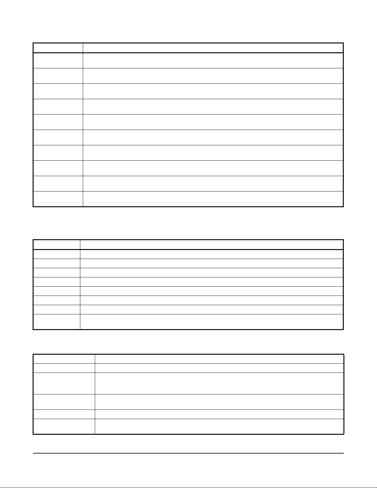
Table 6: A99 Temperature Sensors Selection Chart1 (Part 2 of 2)
Product Code Description
A99BB-300C PTC Temperature Sensor: Standard probe 2 in. (5.1 cm) with 9.8 ft (3.0 m) PVC cable;
A99BB-400C PTC Temperature Sensor: Standard probe 2 in. (5.1 cm) with 13.1 ft (4.0 m) PVC cable;
A99BB-600C PTC Temperature Sensor: Standard probe 2 in. (5.1 cm) with 19.7 ft (6.0 m) PVC cable;
A99BC-25C
A99BC-100C
A99BC-300C
A99BC-500C
A99BC-1500C
A99CB-200C PTC Temperature Sensor: Extended probe 6 in. (15.2 cm) with 6.6 ft (2.0 m) PVC cable;
A99CB-600C PTC Temperature Sensor: Extended probe 6 in. (15.2 cm) with 19.7 ft (6.0 m) PVC cable;
1. When any A99 Series Temperature Sensor is connected to a standard A421 control model, the range of displayed
temperature values is -40 to 212ºF or -40 to 100ºC.
1
Ambient operating temperature range: -40 to 212ºF (-40 to 100ºC)
Ambient operating temperature range: -40 to 212ºF (-40 to 100ºC)
Ambient operating temperature range: -40 to 212ºF or (-40 to 100ºC)
PTC Temperature Sensor: Standard probe 2 in. (5.1 cm) with 9-7/8 in. (0.25 m) high-temperature silicon
cable; Ambient operating temperature range: -40 to 212ºF (-40 to 100ºC)
1
PTC Temperature Sensor: Standard probe 2 in. (5.1 cm) with 3.3 ft (1.0 m) high-temperature silicon
cable; Ambient operating temperature range: -40 to 212ºF (-40 to 100ºC)
1
PTC Temperature Sensor: Standard probe 2 in. (5.1 cm) with 9.8 ft (3.0 m) high-temperature silicon
cable; Ambient operating temperature range: -40 to 248ºF (-40 to 120ºC)
1
PTC Temperature Sensor: Standard probe 2 in. (5.1 cm) with 16.4 ft (5.0 m) high-temperature silicon
cable; Ambient operating temperature range: -40 to 248ºF (-40 to 120ºC)
1
PTC Temperature Sensor: Standard probe 2 in. (5.1 cm) with 49.2 ft (15.0 m) high-temperature silicon
cable; Ambient operating temperature range: -40 to 248ºF (-40 to 120ºC)
Ambient operating temperature range: -40 to 212ºF (-40 to 100ºC)
Ambient operating temperature range: -40 to 212ºF (-40 to 100ºC)
Table 7: Accessories
Product Code Description
BKT287-1R 12 in. (305 mm) long DIN rail section
BKT287-2R 36 in. (914 mm) long DIN rail section
PLT344-1R Two End Clamps for DIN rail sections
A99-CLP-1 Surface Mounting Clip for A99B and A99C Series Temperature Sensors
SHL10-603R Sun Shield for A99B and A99C Series Temperature Sensors
BOX10A-603R PVC Enclosure for A99B and A99C Series Temperature Sensors
WEL11A-601R Copper and brass immersion well for applying sensor in fluid applications
TE-6300W-102 Stainless steel immersion well for applying A99 sensors in fluid applications. (A99CB Type sensors with
extended probe are recommended for use with this immersion well.)
Technical Specifications
Table 8: A421 Series Electronic Temperature Controls (Part 1 of 2)
Power Consumption 1.8 VA Maximum
Supply Power 110/120 or 208/230/240 VAC, 50/60 Hz
Ambient Conditions Operating: Type 1 Models: -40 to 150°F (-40 to 66°C), 0 to 95% RH Non-condensing
Type 4X Models: -40 to 140°F (-40 to 60°C), 0 to 95% RH Non-condensing
Shipping and Storage: All Models: -40 to 185°F (-40 to 85°C), 0 to 95% RH Non-condensing
Temperature Control
Range
Input Signal 1,035 ohm at 77F (25C) for A99 PTC temperature sensors
Accuracy Combined accuracy of A421 control and A99 sensor: ±2F (±1C) between 5F and 167F
-40 to 212°F or -40 to 100°C
(-15C and 75C); diverging to ±3F (±2C) at -40F (-40C) and ±3F (±2C) at 212F (100C)
A421 Series Electronic Temperature Controls with Cycle Timer Installation Instructions
15
Page 16
Table 8: A421 Series Electronic Temperature Controls (Part 2 of 2)
Sensor Offset Range ±5ºF or ±3ºC
Enclosure Material Type 1, IP20 High-Impact Thermoplastic or
Type 4X, IP66 Watertight, Corrosion-Resistant, High-Impact Thermoplastic
Note: To Maintain Type 4X / IP66 Rating, Tighten Enclosure Screws to: 10-12 in·lb
Compliance North America: cULus Listed; UL 60730, File E27734, Vol. 1; FCC Compliant to
CFR47, Part 15, Subpart B, Class B
Industry Canada (IC) Compliant to Canadian ICES-003, Class B limits
Europe: CE Mark – Johnson Controls, Inc. declares that this product is in compliance with the
essential requirements and other relevant provisions of the EMC Directive; Low Voltage Directive.
Australia and New Zealand: RCM, Australia/NZ Emissions Compliant
Table 9: A421 Temperature Control Output Relay Contacts Electrical Ratings
Agency and File UL 60730 and EN 60730
Applied AC Voltage at 50/60 Hz
Horsepower LC/LNO (LC/LNC) 1 (0.25) 1 (0.3) 1 (0.5)
Full Load Amperes LC/LNO (LC/LNC) 16 (5.8) 9.2 (4) 8 (4.9)
Locked Rotor Amperes LC/LNO (LC/LNC) 96 (34.8) 55.2 (24) 48 (29.4)
Resistive Amperes LC/LNO (LC/LNC) 15 (10) 10 (10) 10 (10)
Pilot Duty VA LC/LNO (LC/LNC) 125 (125) 125 (125) 125 (125)
120 VAC 208 VAC 240 VAC
Table 10: UL Conformity Declaration Information
Information Description
Purpose of Control Sensing Control / Operating Control
Construction of Control Electronic Independently Mounted Control
Number of Cycles 30,000 Cycles
Method of Mounting Control Mounting Screws or DIN Rail
Type 1 or Type 2 Action Type 1.B (Micro-disconnection)
External Pollution Situation All Models: A421 [ ] B: Pollution Degree 3
All Models: A421 [ ] E: Pollution Degree 4
Internal Pollution Situation Pollution Degree 2
Heat and Fire Resistance Category D
Rated Impulse Voltage 4000 V
Ball Pressure Temperature 128C
Cover Screw Torque Requirements
Instruction
All Models: A421 [ ] E: To Maintain Type 4X / IP66 Rating, Tighten Enclosure
Screws to: 10 - 12 in·lb
Table 11: A99B Series Positive Temperature Coefficient Sensors (Part 1 of 2)
Sensing Range
Reference Resistance 1,035 ohms at 77°F (25°C) and 855 ohms at 32°F (0°C)
Accuracy 0.9°F (0.5°C) between 5°F and 167°F (-15°C and 57°C). Refer to the A99B Series
Sensor Construction Probe: Stainless Steel
1
Type A99BA and A99BB: -40 to 212°F (-40 to 100°C)
Type A99BC: -40 to 248°F (-40 to 120°C)
Temperature Sensors Product/Technical Bulletin (LIT-125186) for accuracy rating
outside of this temperature range.
A421 Series Electronic Temperature Controls with Cycle Timer Installation Instructions
16
Page 17
Johnson Controls® and PENN® are registered trademarks of Johnson Controls, Inc. in the
United States of America and/or other countries. All other trademarks used herein are the property
of their respective owners. © Copyright 2016 by Johnson Controls, Inc. All rights reserved.
Building Efficiency
507 E. Michigan Street, Milwaukee, WI 53202
Table 11: A99B Series Positive Temperature Coefficient Sensors (Part 2 of 2)
Sensor Cable Sheath Type A99BA: Shielded PVC Cable
Type A99BB: PVC Cable
Type A99BC: High Temperature Silicon Cable
Wire Gauge 22 AWG
Ambient Operating Conditions Type A99BA and A99BB: -40 to 212°F (-40 to 100°C); 0 to 100% RH, Condensing
Ambient Storage Conditions Type A99BA and A99BB: -40 to 221°F (-40 to 105°C); 0 to 100% RH, Condensing
Shipping Weight 1.4 oz (41 g) for 6 1/2 ft (2 m) sensor
Accessories See Table 7
1. When any A99 Series Temperature Sensor is connected to a standard A421 control model, the range of displayed
temperature values is -40 to 212ºF or -40 to 100ºC.
The performance specifications are nominal and conform to acceptable industry standards. For application at conditions beyond these
specifications Johnson Controls, Inc. shall not be liable for damages resulting from misapplication or misuse of its products.
United States Emissions Compliance
This equipment has been tested and found to comply with the limits for a Class B digital device, pursuant to Part 15 of the FCC Rules. These
limits are designed to provide reasonable protection against harmful interference in a residential installation. This equipment generates, uses
and can radiate radio frequency energy and, if not installed and used in accordance with the instructions, may cause harmful interference to
radio communications. However, there is no guarantee that interference will not occur in a particular installation. If this equipment does cause
harmful interference to radio or television reception, which can be determined by turning the equipment off and on, the user is encouraged to try
to correct the interference by one or more of the following measures:
- Reorient or relocate the receiving antenna.
- Increase the separation between the equipment and receiver.
- Connect the equipment into an outlet on a circuit different from that to which the receiver is connected.
- Consult the dealer or an experienced radio/TV technician for help.
Canadian Emissions Compliance
This Class (B) digital apparatus meets all the requirements of the Canadian Interference-Causing Equipment Regulations.
Cet appareil numérique de la Classe (B) respecte toutes les exigences du Règlement sur le matériel brouilleur du Canada.
Type A99BC: -40 to 248°F (-40 to 120°C); 0 to 100% RH, Condensing
Type A99BC: -40 to 266°F (-40 to 130°C); 0 to 100% RH, Condensing
European Single Point of Contact: NA/SA Single Point of Contact: APAC Single Point of Contact:
JOHNSON CONTROLS
WESTENDHOF 3
45143 ESSEN
GERMANY
JOHNSON CONTROLS
507 E MICHIGAN ST
MILWAUKEE WI 53202
USA
JOHNSON CONTROLS
C/O CONTROLS PRODUCT
MANAGEMENT
NO. 22 BLOCK D NEW DISTRICT
WUXI JIANGSU PROVINCE 214142
CHINA
A421 Series Electronic Temperature Controls with Cycle Timer Installation Instructions
Published in U.S.A. www.johnsoncontrols.com
17
 Loading...