

Penguin Computing Arctica Series, Arctica 1600cs, Arctica 3200cs, Arctica 4808xs Installation Manual
Page 1

Arctica Ethernet Switches Installation Guide
Models: Arctica 1600cs, Arctica 3200cs, Arctica 4808xs
Version 1.0
2018-09-25
Page 2

2
About this Manual
This manual describes the installation and basic use of the Penguin Computing Arctica Ethernet
Switches.
Intended Audience
This manual is intended for IT managers and system administrators.
Conventions
The following icons are used throughout this document to indicate information that is important to
the user.
This icon makes recommendations to the user.
This icon indicates information that is helpful to the user.
This icon indicates a situation that can
potentially cause damage to hardware software.
This icon indicates a situation that can potentially cause personal injury.
This icon indicates a situation that can potentially cause personal injury.
Rev. 1.0 Penguin Computing
Page 3

3
Table of Contents
About this Manual .......................................................................................................................... 2
Intended Audience ................................................................................................................................. 2
Conventions ........................................................................................................................................... 2
Table of Contents ............................................................................................................................ 3
List of Tables ................................................................................................................................... 5
List of Figures .................................................................................................................................. 6
Introduction to Arctica Ethernet Switch Systems .............................................................................. 8
Overview ................................................................................................................................................ 8
Speed and Switching ............................................................................................................................... 9
Management Interfaces, PSUs and Fans ................................................................................................ 10
Installation ................................................................................................................................... 11
Safety Warnings ................................................................................................................................... 11
System Installation and Initialization ..................................................................................................... 14
Air flow ................................................................................................................................................ 15
Package Contents ................................................................................................................................. 16
19” Systems Mounting Options ............................................................................................................. 17
Mount the system into the rack ................................................................................................................................... 19
Removing the System from the Rack ............................................................................................................................ 23
Telescopic Rail Kit for Arctica 3200cs ..................................................................................................... 23
Removing the System from the Rack ............................................................................................................................ 28
Static Rail Kit for Arctica 4808xs ............................................................................................................. 29
Side by Side Mounting for Arctica 1600cs Rail Kit ................................................................................... 33
Cable Installation .................................................................................................................................. 40
Breakout Cables and Adapters...................................................................................................................................... 41
Initial Power On .................................................................................................................................... 43
FRU Replacements ................................................................................................................................ 45
Power Supply ................................................................................................................................................................ 45
Fans ............................................................................................................................................................................... 47
Interfaces ..................................................................................................................................... 48
Supported Interfaces ............................................................................................................................ 48
Data Interfaces .............................................................................................................................................................. 48
Speed ............................................................................................................................................................................ 49
RS232 (Console) ............................................................................................................................................................ 49
Management ................................................................................................................................................................ 49
USB ................................................................................................................................................................................ 50
Rev. 1.0 Penguin Computing
Page 4

4
Reset Button ................................................................................................................................................................. 50
Status and Port LEDs ..................................................................................................................................................... 50
LEDs ..................................................................................................................................................... 50
LED Notifications ........................................................................................................................................................... 50
Inventory Information .......................................................................................................................... 60
Software Management ................................................................................................................. 62
Troubleshooting ............................................................................................................................ 63
Troubleshooting Instructions ................................................................................................................ 63
Specifications ................................................................................................................................ 64
Arctica 3200cs Series ............................................................................................................................. 64
Arctica 4808xs Series ............................................................................................................................ 66
Arctica 1600cs Series ............................................................................................................................. 68
Appendix B: Disassembly and Disposal ....................................................................................... 71
Disassembly Procedure ......................................................................................................................... 71
Rev. 1.0 Penguin Computing
Page 5

5
List of Tables
Table 1: Speed and Switching Capabilities ............................................................................................... 9
Table 2: Management Interfaces, PSUs and Fans .................................................................................. 10
Table 3: Air flow color legend ................................................................................................................. 16
Table 4: Installation Kit ........................................................................................................................... 17
Table 5: Installation Kit ........................................................................................................................... 23
Table 6: Installation Kit ........................................................................................................................... 30
Table 7: Installation Kit ........................................................................................................................... 34
Table 8: High Power/LR4 Transceivers Support ..................................................................................... 48
Table 9: LEDs Symbols ............................................................................................................................ 51
Table 10: System Status LED Assignments ............................................................................................. 53
Table 11: Power Supply Unit Status Front LED Assignments for Arctica 3200cs and Arctica 4808xs .... 56
Table 12: Bad Port LED Assignments: Bad Port LED Assignments .......................................................... 58
Table 13: Troubleshooting ...................................................................................................................... 63
Table 14: Arctica 3200cs Specifications .................................................................................................. 64
Table 15: Arctica 4808xs Specifications .................................................................................................. 66
Table 16: Arctica 1600cs Specifications .................................................................................................. 68
Table 17: OPNs for Replacement Parts ................................................................................................... 70
Rev. 1.0 Penguin Computing
Page 6

6
List of Figures
Figure 1: Arctica 3200cs Front Side View ................................................................................................. 9
Figure 2: Arctica 4808xs Front Side View ................................................................................................. 9
Figure 3: Arctica 1600cs Front Side View ................................................................................................. 9
Figure 4: Arctica 3200cs and Arctica 4808xs Rear Side View ................................................................... 9
Figure 5: Air Flow Direction Marking - Power Side Inlet to Connector Side Outlet ............................... 15
Figure 6: Air Flow Direction Marking - Connector Side Inlet to Power Side Outlet ............................... 15
Figure 7: Rack Rail Kit Parts .................................................................................................................... 18
Figure 8: Installation options .................................................................................................................. 19
Figure 9: Attaching the Rails to the Chassis ............................................................................................ 20
Figure 10: Attaching the Brackets to the Chassis ................................................................................... 21
Figure 11: Installing the Cage Nuts ......................................................................................................... 21
Figure 12: Attaching the Brackets to the Rack ....................................................................................... 22
Figure 13: Sliding the Blades in the Rails ................................................................................................ 22
Figure 14: Rack Rail Kit Parts .................................................................................................................. 24
Figure 15: Rails Separation ..................................................................................................................... 25
Figure 16: Installing the Cage Nuts ......................................................................................................... 26
Figure 17: Mounting the Outer Rails into the Rack ................................................................................ 26
Figure 18: Attaching the Inner Rails to the Chassis ................................................................................ 27
Figure 19: Securing the Chassis in the Inner Rails .................................................................................. 27
Figure 20: Sliding the Switch into the Rack ............................................................................................ 28
Figure 21: Pulling the Unit Outwards ..................................................................................................... 29
Figure 22: Locking Mechanism ............................................................................................................... 29
Figure 23: Rack Rail Kit Parts .................................................................................................................. 30
Figure 24: Installation Options ............................................................................................................... 31
Figure 25: Attaching the Rails to the Chassis .......................................................................................... 32
Figure 26: Installing the Cage Nuts ......................................................................................................... 32
Figure 27: Sliding the Blades in the Rails ................................................................................................ 33
Figure 28: Rack Rail Kit Parts .................................................................................................................. 35
Figure 29: Coupling the Cables with Cable-ties ...................................................................................... 36
Figure 30: Coupled Cables - Rear View ................................................................................................... 36
Figure 31: Cables within the Rail ............................................................................................................ 37
Figure 32: Attach the blades to the system ........................................................................................... 37
Figure 33: Attached Rail with Threaded Cables - Top View ................................................................... 38
Figure 34: Sliding the Frame Sliders into the Rails ................................................................................. 38
Figure 35: Installing the Cage Nuts ......................................................................................................... 39
Figure 36: Attaching the Frame to the Rack ........................................................................................... 39
Figure 37: Sliding the System’s Blades in the Rails ................................................................................. 40
Figure 38: Arctica 3200cs and Arctica 1600cs Cable Orientation ........................................................... 41
Figure 39: Arctica 4808xs Cable Orientation .......................................................................................... 41
Figure 40: Breakout or Fanout ................................................................................................................ 42
Rev. 1.0 Penguin Computing
Page 7

7
Figure 41: Arctica 3200cs Splitting Options ............................................................................................ 42
Figure 42: Arctica 1600cs Splitting Options ............................................................................................ 43
Figure 43: System Status LEDs 5 Minutes After Power On in Arctica 3200cs ........................................ 44
Figure 44: System Status LEDs 5 Minutes After Power On .................................................................... 44
Figure 45: System Status LEDs 5 Minutes After Power On ..................................................................... 44
Figure 46: Two Power Inlets - Electric Caution Notifications ................................................................. 45
Figure 47: PS Unit Pulled Out.................................................................................................................. 46
Figure 48: Fan Module Latches ............................................................................................................... 47
Figure 49: Using 4.5W Modules on Ports 49, 50, 55, 56 in Arctica 4808xs ............................................ 49
Figure 50: System Status LEDs - Front and Rear Sides in Arctica 3200cs ............................................... 52
Figure 51: System Status LEDs - Front and Rear Sides in Arctica 4808xs .............................................. 52
Figure 52: System Status LED in Arctica 1600cs ..................................................................................... 52
Figure 53: Fan Status LED in Arctica 3200cs - Front and Rear Sides ...................................................... 53
Figure 54: Fan Status LED in Arctica 4808xs - Front and Rear Sides ...................................................... 54
Figure 55: Fan Status LED in Artica 1600cs ............................................................................................. 54
Figure 56: Power Status LED ................................................................................................................... 55
Figure 57: Arctica 3200cs and Arctica 4808xs Rear Side ........................................................................ 56
Figure 58: Arctica 4808xs SFP+ Port LEDs ............................................................................................... 59
Figure 59: Arctica 4808xs QSFP28 Port LEDs .......................................................................................... 59
Figure 60: Arctica 1600cs Port LEDs ....................................................................................................... 59
Figure 61: Arctica 3200cs Pull-out Tab ................................................................................................... 60
Figure 62: Arctica 4808xs Inventory Information Illustration ................................................................ 61
Figure 63: Arctica 1600cs Pull-out Tab ................................................................................................... 61
Rev. 1.0 Penguin Computing
Page 8

8
Introduction to Arctica Ethernet Switch Systems
Overview
Penguin Computing Arctica 1U switch systems are an ideal spine and Top of Rack (ToR) solution,
allowing maximum flexibility, with port speeds spanning from 10Gb/s to 100Gb/s per port, and port
density that enables full rack connectivity to any server at any speed. The uplink ports allow a variety
of blocking ratios that suit any application requirement. Powered by the Spectrum ASIC, the systems
carry whopping switching and processing capacities in a compact 1U form factor.
Keeping with the Penguin Computing tradition of setting performance record switch systems, the
Spectrum based systems introduce the world’s lowest latency for 100GbE switching and routing
elements—while having the lowest power consumption in the market. They enable the use of 10, 25,
40, 50 and 100GbE in a large scale without changing power infrastructure facilities.
The Spectrum based switch systems are a part of Penguin Computing’s complete end-to-end solution,
which provides 10GbE through 100GbE interconnectivity within the data center. These systems
introduce hardware capabilities for multiple tunneling protocols that enable increased reachability
and scalability for today’s data centers. Implementing MPLS, NVGRE and VXLAN tunneling
encapsulations in the network layer of the data center allows more flexibility for terminating a tunnel
by the network, in addition to termination on the server endpoint.
While Spectrum provides the thrust and acceleration that powers the switch systems, they get yet
another angle of capabilities, running with a powerful x86-based processor, which allows them to not
only be the highest performing switch fabric elements, but also grants them the ability to incorporate
a Linux running server into the same device. This opens up multiple application aspects of utilizing the
high CPU processing power and the best switching fabric, to create a powerful machine with unique
appliance capabilities that can improve numerous network implementation paradigms.
The Spectrum™ based 1U switch systems support the Open Network Install Environment (ONIE) for
zero touch installations of network operating systems. All Ethernet systems can be purchased
preloaded with Cumulus Linux.
Rev. 1.0 Penguin Computing
Page 9
9
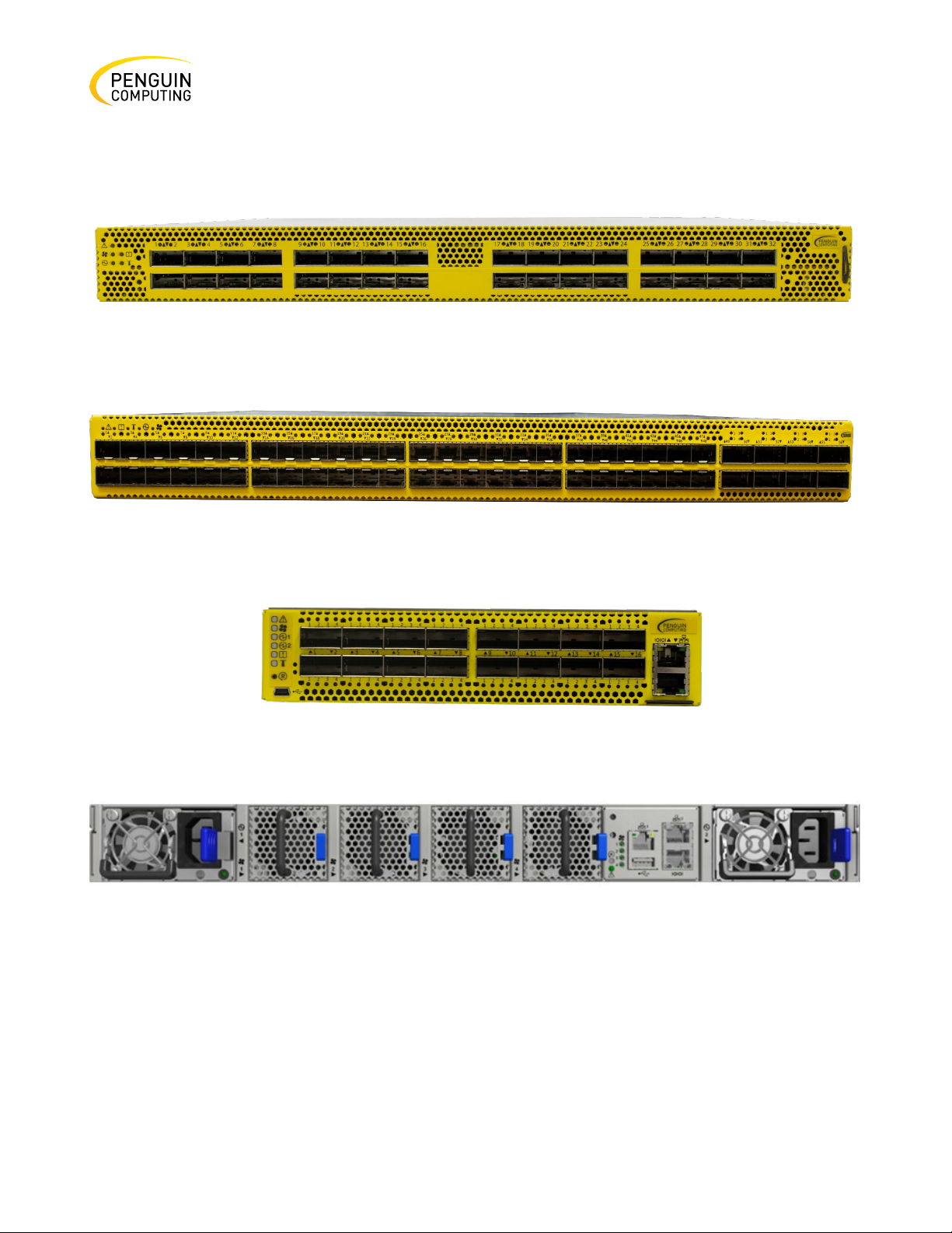
Figure 1: Arctica 3200cs Front Side View
Figure 2: Arctica 4808xs Front Side View
Figure 3: Arctica 1600cs Front Side View
Figure 4: Arctica 3200cs and Arctica 4808xs Rear Side View
Speed and Switching
This table describes maximum throughput and interface speed per system model.
Table 1: Speed and Switching Capabilities
Rev. 1.0 Penguin Computing
Page 10

10
Model
40/50/100GbE QSFP28
Throughpu
Arctica
64 (using QSFP to SFP breakout
32
3.2 Tb/s
Arctica
Total 64, 48x SFP+ 16 (using
8
2 Tb/s
Arctica
64 (using QSFP to SFP breakout
16 (or 32 50GbE inter- faces
1.6 Tb/s
System
USB
MGT
Console
PSU
Fan
Arctica
Rear
Rear (2 ports)
Rear
2 units
4 units
Arctica
Rear
Rear (2 ports)
Rear
2 units
4 units
Arctica
Front (mini USB)
Front (1 port)
Front
2 units (non-
4 units (non-
System
3200cs
4808xs
1600cs
10/25GbE SFP28 Interfaces*
cables)
QSFP to SFP breakout cables)
cables)
Interfaces*
when using QSFP to 2xQSFP
breakout cables).
Management Interfaces, PSUs and Fans
This table lists the various management interfaces, PSUs and fans per system model.
Table 2: Management Interfaces, PSUs and Fans
Max
3200cs
4808xs
1600cs
replaceable)
replaceable)
Rev. 1.0 Penguin Computing
Page 11
11
1. Installation Instructions
power source.
3. Heavy Equipment
avoid injuries.
4. Risk of Electric Shock!
cavity. Do not insert tools or body parts into the fan module cavity.
5. Excessive temperature
clearance around the ventilation openings.
Installation
Safety Warnings
Read all installation instructions before connecting the equipment to the
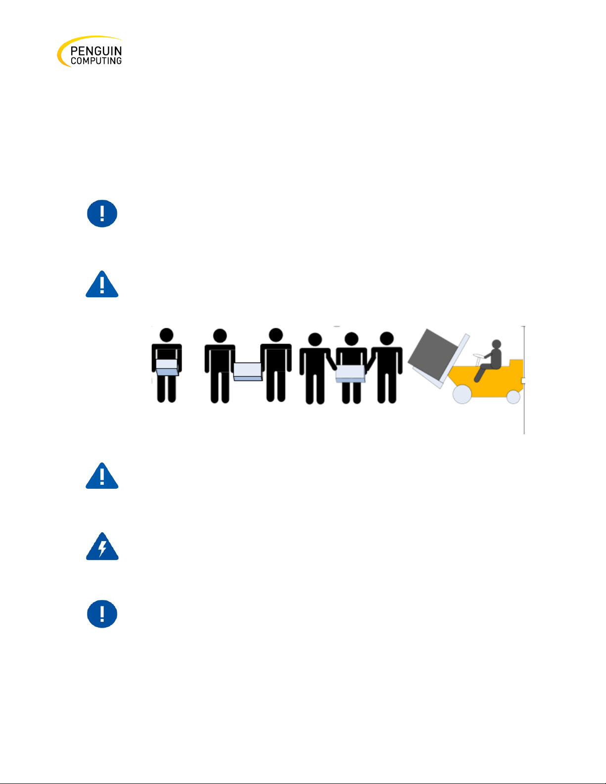
2. Bodily injury due to excessive weight lifting.
Use enough people to safely lift this product.
This equipment is heavy and should be moved using a mechanical lift to
With the fan module removed power pins are accessible within the module
This equipment should not be operated in an area with an ambient
temperature exceed-ing the maximum recommended: 45°C (113°F).
Moreover, to guarantee proper ventilation, allow at least 8cm (3 inches) of
Rev. 1.0 Penguin Computing
Page 12

12
6. Stacking the Chassis
falls, it can cause bodily injury and equipment damage.
7. Redundant Power Supply Connection - Electrical Hazard
securely fastened.
8. Double Pole/Neutral Fusing
opening the cover of this product or touching any internal parts.
9. Multiple Power Inlets — Risk of electric shock and energy hazard.
ensure a powered-down state inside of the switch platform.
10. During Lightning - Electrical Hazard
connect or disconnect any cables.
11. CopperCable Connecting/Disconnecting
for special warnings/ instructions.
12. Rack Mounting and Servicing
the rack with equip- ment starting from the bottom to the top.
13. Equipment Installation
and qualified personnel.
14. Equipment Disposal
The chassis should not be stacked on any other equipment. If the chassis
This product includes a redundant power or a blank in its place. If a blank is
present, do not operate the product with the blank cover removed or not
This system has double pole/neutral fusing. Remove all power cords before
The PSUs are all independent. Be sure to disconnect all power supplies to
During periods of lightning activity, do not work on the equipment. Do not
Copper cables are heavy and inflexible, as such they should be carefully
attached or detached from the connectors. Refer to the cable manufacturer
When this product is mounted or serviced in a rack, special precautions must
be taken to ensure that the system remains stable. In general you should fill
This equipment should be installed, replaced, and/or serviced only by trained
Rev. 1.0 Penguin Computing
Page 13

13
Disposal of this equipment should be in accordance with all national laws and
regulations.
15. Local and National Electrical Codes
electrical codes.
16. Installation Codes
and the Canadian Electri-cal Code.
17. Battery Replacement
Dispose of used batteries according to the instructions.
18. UL Listed and CSA Certified Power Supply Cord
plug rated at 250 V, 10 A.
19. Installation codes
and the Canadian Electrical Code.
This equipment should be installed in compliance with local and national
This device must be installed according to the latest version of the country
national electrical codes. For North America, equipment must be installed in
accordance to the applicable requirements in the US National Electrical Code
Warning: Replace only with UL Recognized battery, certified for maximum
abnormal charging current not less than 4mA.
There is a risk of explosion if the battery is replaced with a battery of an
incorrect type.
Rev. 1.0 Penguin Computing
For a North American power connection, select a power supply cord that is
UL Listed and CSA Certified, 3-conductor, [16 AWG], terminated with a
molded plug rated at 125 V, [13 A], with a minimum length of 1.5m [six feet]
but no longer than 4.5m.
For European connection, select a power supply cord that is internationally
harmonized and marked “<HAR>”, 3-conductor, minimum 1.0 mm2 wire,
rated at 300 V, with a PVC insulated jacket. The cord must have a molded
This device must be installed according to the latest version of the country
national electrical codes. For North America, equipment must be installed in
accordance to the applicable requirements in the US National Electrical Code
Page 14
14
20. Interconnecting the Units
certified type DP-1 or DP-2. (Note- when residing in non LPS circuit)
21. Overcurrent Protection
20 A must be incorporated in the building wiring.
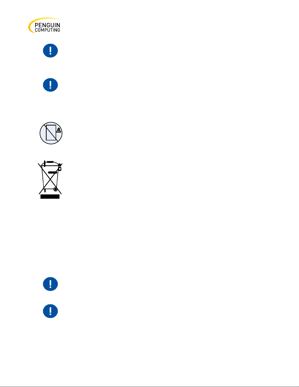
22. Do Not Use the Switch as a Shelf or Work Space
and maintenance
23. WEEE Directive
environmentally friendly way.
The rack mounting holes conform to the EIA-310 standard for 19-inch
maintain good airflow at ambient temperature.
Unless otherwise specified, Penguin Computing products are designed to
for gaseous contamination and ISO 14644-1 class 8 for cleanliness level.
Cables for connecting to the unit RS232 and Ethernet Interfaces must be UL
A readily accessible Listed branch circuit overcurrent protective device rated
CAUTION: Slide/rail mounted equipment is not to be used as a shelf or a work
space. The rails are not intended for sliding the unit away from the rack. It is
for permanent instal- lation at final resting place only, not used for service
According to the WEEE Directive 2002/96/EC, all waste electrical and
electronic equipment (EEE) should be collected separately and not disposed
of with regular household waste.
Dispose of this product and all of its parts in a responsible and
System Installation and Initialization
Installation and initialization of the system require attention to the normal mechanical, power, and
thermal precautions for rack-mounted equipment.
Rev. 1.0 Penguin Computing
racks. Take precautions to guarantee proper ventilation in order to
work in an environmentally controlled data center with low levels of
gaseous and dust (particulate) contamination.
The operation environment should meet severity level G1 as per ISA 71.04
Page 15
15
This is the installation procedure for the system:
1.
Follow the safety warnings in the previous section.
2.
Pay attention to the air flow consideration within the system and rack - refer to the Air Flow
section below.
3.
Make sure that none of the package contents are missing or damaged - see Package Contents
below.
4.
Mount the system into a rack enclosure - see Systems Mounting Options.
5.
Power on the system - refer to the Initial Power On section below.
6.
[Optional]: FRU replacements are described further below in this document.
Air flow
The following information does not apply to Arctica 1600cs. In the 1600cs
systems, the fan units are non-replaceable.
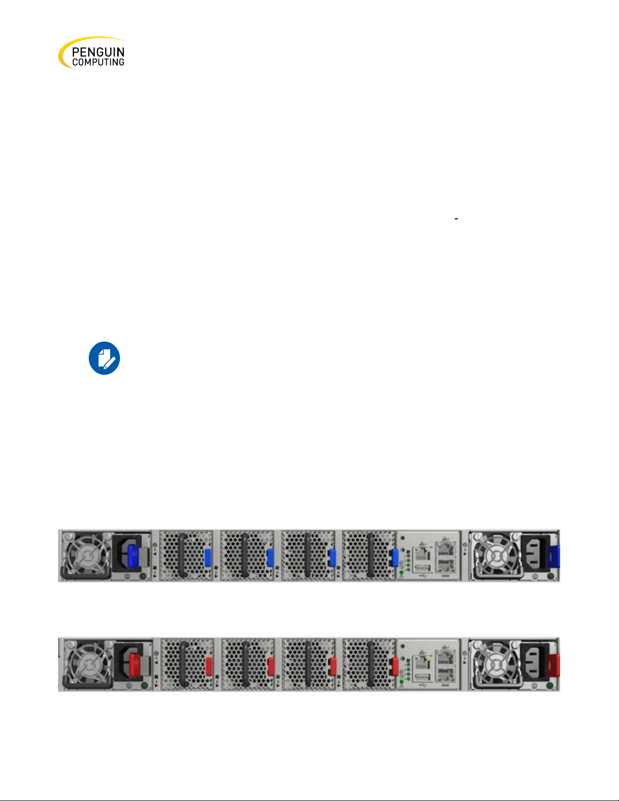
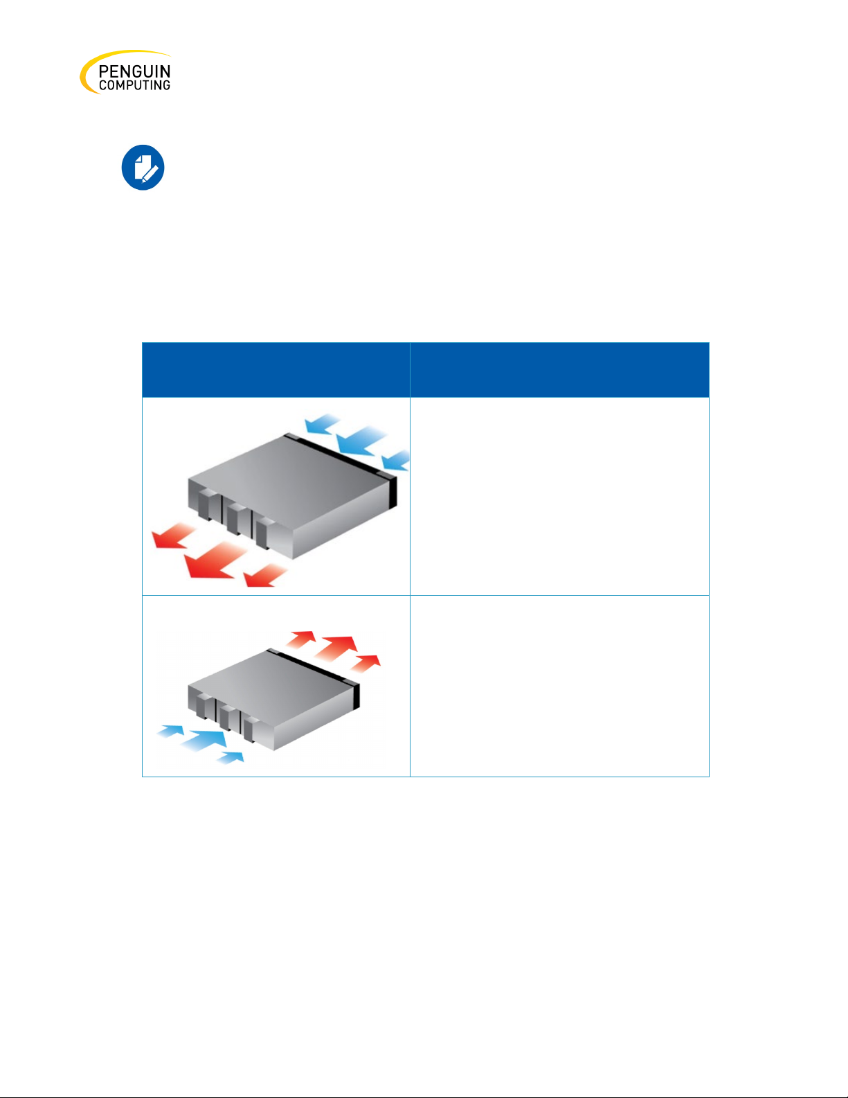
Penguin Computing’s Arctica Switches are offered with two air flow patterns:
• Power (rear) side inlet to connector side outlet - marked with blue power supplies/fans- FRUs’
handles, as shown in Figure 7.
• Connector (front) side inlet to power side outlet - marked with red power supplies/fans FRUs’
handles, as shown in Figure 8.
Figure 5: Air Flow Direction Marking - Power Side Inlet to Connector Side Outlet
Figure 6: Air Flow Direction Marking - Connector Side Inlet to Power Side Outlet
Rev. 1.0 Penguin Computing
Page 16
16
All servers and systems in the same rack should be planned with the same
in the air flow will affect the heat dissipation.
Connector side inlet to power side outlet.
Power side inlet to connector side outlet.
All FRU components need to have the same air flow direction. A mismatch
The table below provides an air flow color legend and respective OPN designation.
airflow direction.
Table 3: Air flow color legend
Direction Description
Red latches are placed on the power inlet
side.
Blue latches are placed on the power inlet
side.
Package Contents
Before installing your new system, unpack it and check against the parts list below that all the parts
have been sent. Check the parts for visible damage that may have occurred during shipping.
The Arctica 3200cs and Arctica 4808xs package content is as follows:
• 1 – System
• 1 – Rail kit
Rev. 1.0 Penguin Computing
Page 17
17
If anything is damaged or missing, contact your sales representative at
[email protected].
Penguin PN
Rack Size and Rack Depth Range
10026062
Short (17”-24”) or Standard (24”-34”)
• 1 – Power cable for each power supply unit – Type C13-C14
• 1 – Cable retainer for each power supply unit
• 1 – DB9 to RJ-45 2m harness
The Arctica 1600cs package content is as follows:
• 1 – System
• 1 – Power cable for each power supply unit – Type C13-C14
• 1 – DB9 to RJ-451 2m harness
A designated rail kit for the Arctica 1600cs systems can be purchased
separately.
19” Systems Mounting Options
By default, the Arctica 3200cs systems are sold with the Static Rail Kit for Arctica 3200cs. The Arctica
4808xs systems are sold with the Static Rail Kit for Arctica 4808xs. For the telescopic rail kit
installation instructions (can be used with Arctica 3200cs only), see Telescopic Rail Kit for Arctica
3200cs.
The Arctica 1600cs system is sold without a rail kit. A designated rail kit can be purchased separately.
For installation instructions, see Side by Side Mounting for Arctica 1600cs Rail Kit.
At least two people are required to safely mount the system in the rack.
Table 4: Static Rail Kit for 3200cs
Rev. 1.0 Penguin Computing
Page 18
18
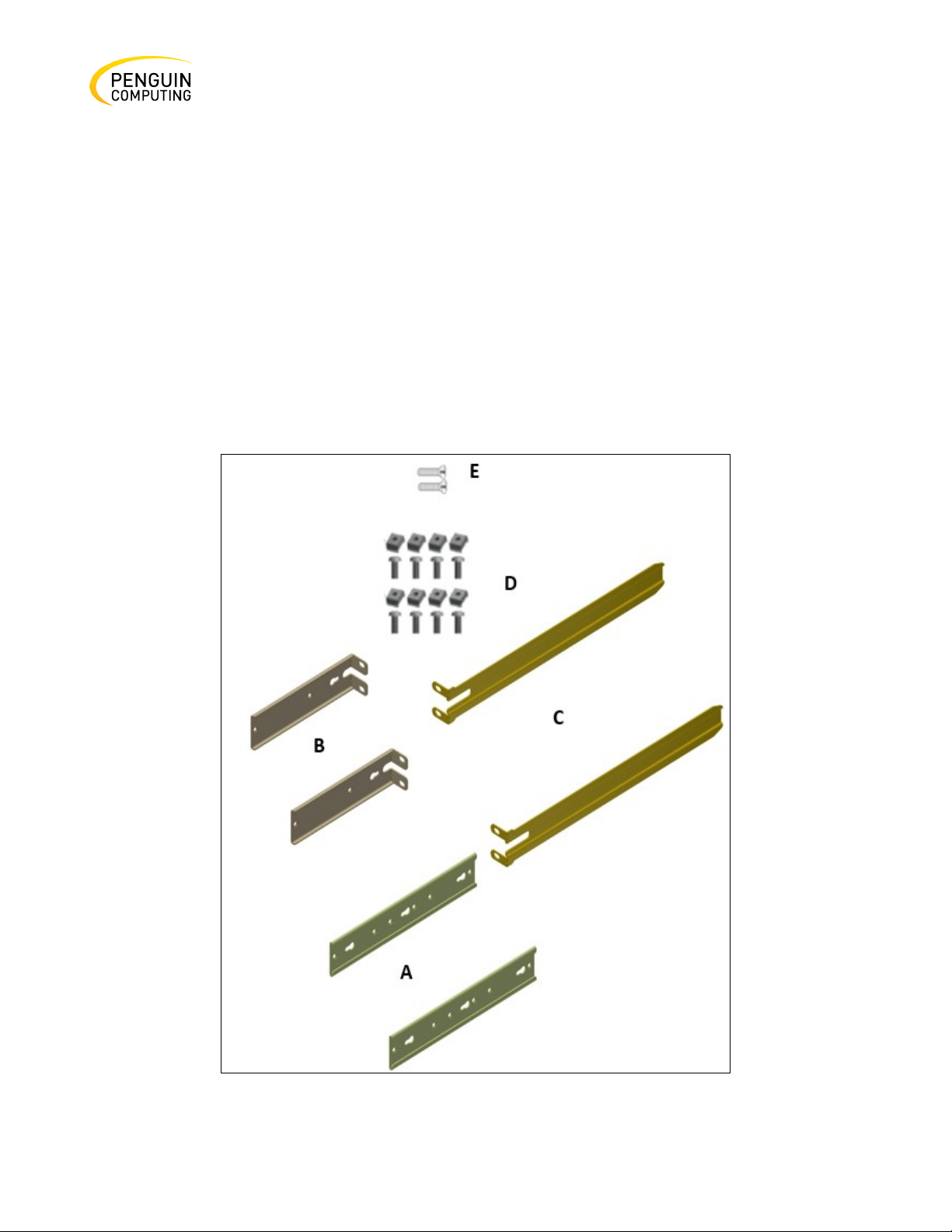
The following parts are included in the static rail kit (see the figure below):
• 2x Rack mount rails (A)
• 2x Rack mount brackets (B)
• 2x Rack mount blades (C)
• 8x M6 Standard cage nuts¹ ² and 8x M6 Standard pan-head Phillips screws¹ (D)
• 4x Phillips100 DEG F.H TYPE-I ST.ST 6-32 X 1/4 screw with around patch (E)
¹ Other threads are available by special order: M5, 10-32, 12-24
² G-type cage-nut is available by special order.
Figure 7: Rack Rail Kit Parts
Rev. 1.0 Penguin Computing
Page 19
19
Mount the system into the rack
Before mounting the system to the rack, select the way you wish to place the system. Pay attention
to the airflow within the rack cooling, connector and cabling options.
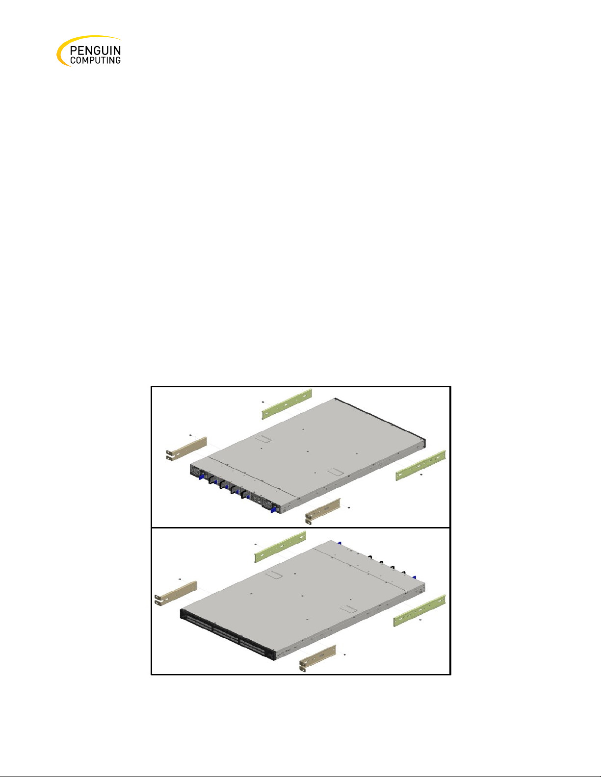
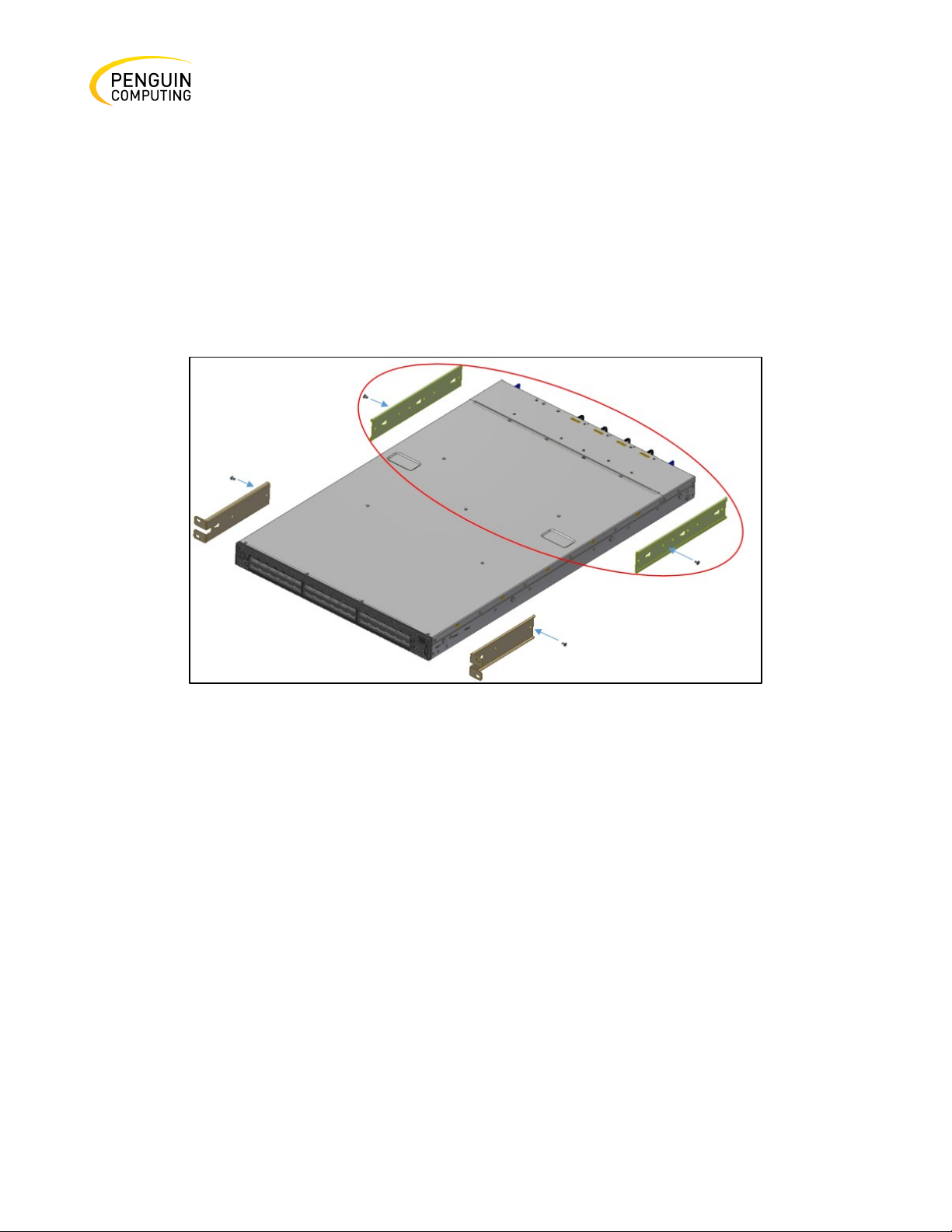
While planning how to place the system, consider the two installation options shown in the figure
below, and review the following points:
• Make sure the system air flow is compatible with your installation selection. It is import- ant
to keep the airflow within the rack in the same direction.
• Note that the part of the system to which you choose to attach the rails (the front panel
direction, as demonstrated in Option 1 or the FRUs direction, as demonstrated in Option
• 2) will determine the system’s adjustable side. The system’s part to which the brackets are
attached will be adjacent to the cabinet.
• The FRU side is extractable. Mounting the rack brackets inverted to the FRU side (Option 2)
will allow you to slide the FRUs, in and out.
Figure 8: Installation options
Rev. 1.0 Penguin Computing
Page 20
20
Refer to Figure 7: Rack Rail Kit Parts above and follow these steps:
Step 1. Attach the left and right rack mount rails (A) to the switch, by gently pushing the switch
chassis’ pins through the slider key holes, until locking occurs.
Step 2. Secure the chassis in the rails by screwing 2 flat head Phillips screws (E) in the designated
points with a torque of 1.5±0.2 Nm. See the figure below.
Figure 9: Attaching the Rails to the Chassis
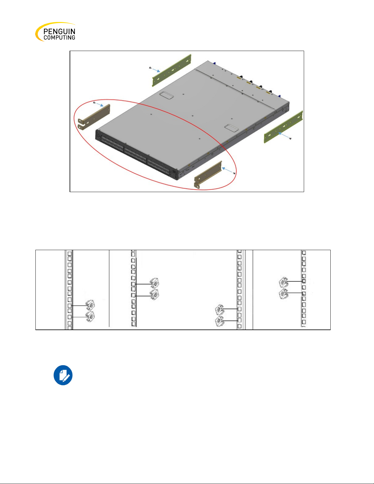
Step 3. Attach the left and right rack mount brackets (B) to the switch, by gently pushing the switch
chassis’ pins through the slider key holes, until locking occurs. Secure the system in the brackets by
screwing the remaining 2 flat head Phillips screws (E) in the designated points with a torque of
1.5±0.2 Nm. See the figure below.
Rev. 1.0 Penguin Computing
Page 21
21
Figure 10: Attaching the Brackets to the Chassis
Step 4. Install 8 cage nuts in the desired 1U slots of the rack: 4 cage nuts in the non-extractable side
(in the top and bottom holes only) and 4 cage nuts in the extractable side.
Figure 11: Installing the Cage Nuts
While each rack U (unit) consists of three holes, the cage nut should be
installed vertically with its ears engaging the top and bottom holes only.
While your installation partner is supporting the system’s weight, perform the following steps:
Rev. 1.0 Penguin Computing
Page 22
22
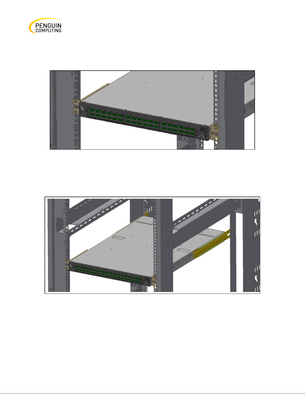
Step 5. Mount the system into the rack enclosure, and attach the brackets installed on the system to
the rack’s posts. Secure the brackets to the rack posts by inserting four M6 screws in the designated
cage nuts, as described in the figure below. Do not tighten the screws yet.
Figure 12: Attaching the Brackets to the Rack
Step 6. Slide the two blades into the left and right rails, and then adjust them to fit the depth of your
rack. Use four M6 screws (D) to fix the blades into the rack. Do not tighten the screws yet.
Figure 13: Sliding the Blades in the Rails
Step 7. Secure the system in the rack by tightening the 8 screws inserted in Step 5 and Step 6 with a
torque of 4.5±0.5 Nm.
Rev. 1.0 Penguin Computing
Page 23

23
Penguin PN
Rack Size and Rack Depth Range
10027052
Short (17"-24" \ 43.1 to 61 cm)
10027053
Standard (24"-34" \ 61 to 86.3 cm)
Removing the System from the Rack
To remove a unit from the rack:
Step 1. Turn off the system and disconnect it from peripherals and from the electrical outlet. While
your installation partner is supporting the system’s weight:
Step 2. Loosen the screws attaching the brackets to the rack. Do not remove them yet.
Step 3. Loosen the screws attaching the blades to the rack, and pull the blades towards you, while
your partner is holding the system.
Step 4. Extract the loosened screws from Step 2 and dismount the system from the rack.
Step 5. Remove the rails and brackets from the chassis by unscrewing 8 screws.
Telescopic Rail Kit for Arctica 3200cs
There are two installation kit options:
• Standard depth systems should be mounted using the standard rail kit.
• Short depth systems can be mounted using either of the rail kits.
Table 5: Installation Kit
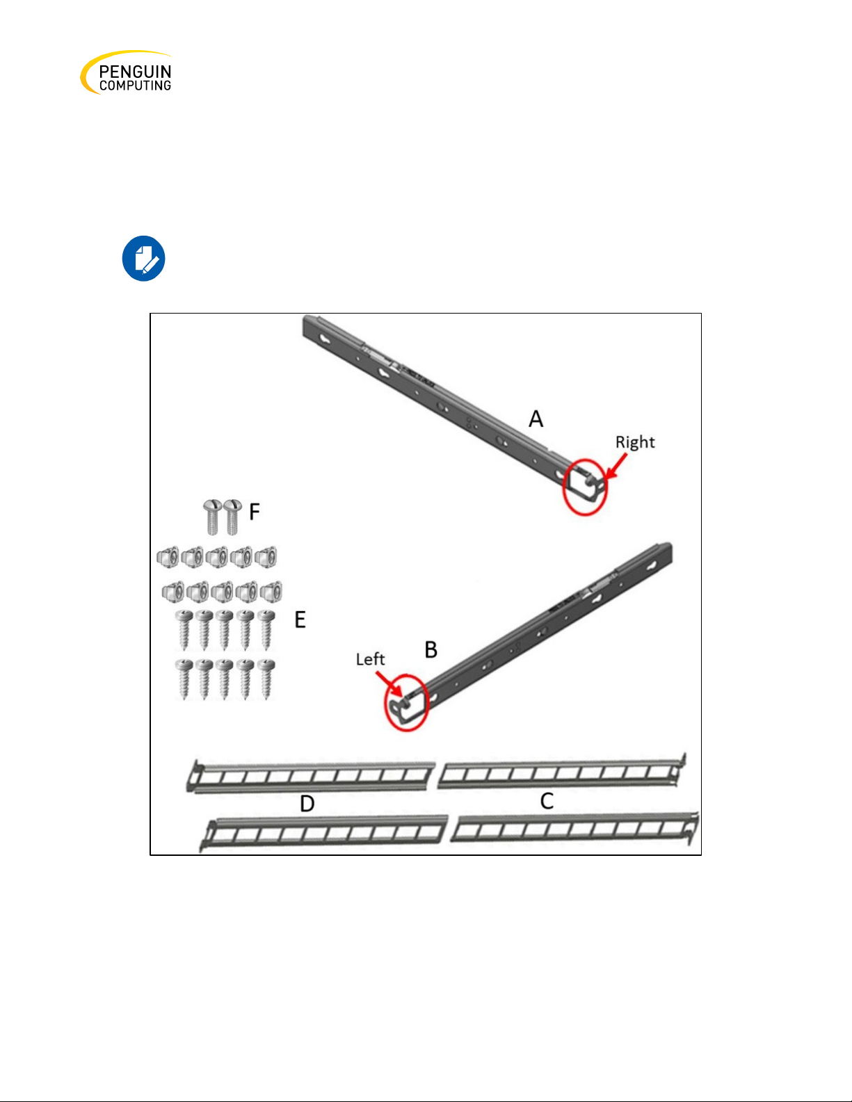
The following parts are included in the rail kit package (see Figure 14: Rack Rail Kit Parts):
• 1x Right inner rail (A)
• 1x Left inner rail (B)
• 2x Outer rails (C)
• 2x Outer rails (D)
• 10x M6 Standard cage nuts¹ ² and 10x M6 Standard pan-head Phillips screws¹ (E)
Rev. 1.0 Penguin Computing
Page 24
24
• 2x Phillips100 DEG F.H TYPE-I ST.ST 6-32 X 1/4 screw with around patch (F)
¹ Other threads are available by special order: M5, 10-32, 12-24
² G-type cage-nut is available by special order.
The rails must be separated prior to the installation procedure. See the
figure below.
Figure 14: Rack Rail Kit Parts
Rev. 1.0 Penguin Computing
Page 25
25
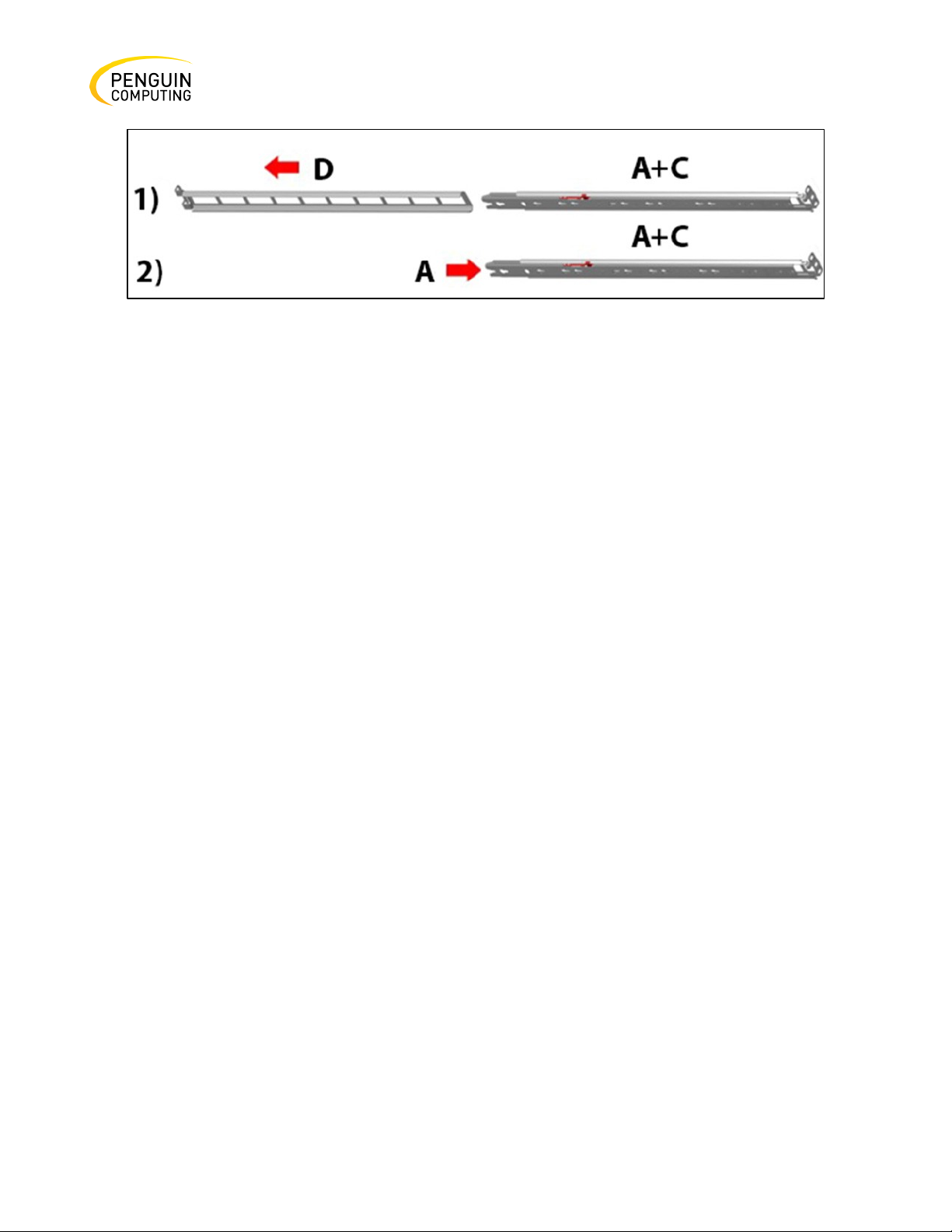
Figure 15: Rails Separation
To separate the rails, follow these steps:
1. Extend the rail assembly by pulling the extension outwards (D).
2. Extract rail A from rail C by pushing it outside from the rear part of the assembly. To allow
complete separation of rail A from rail C, press the quick-release latch.
Before mounting the system to the rack, select the way you wish to place the system. Pay attention
to the airflow within the rack cooling, connector and cabling options.
While planning how to place the system, review the following points:
• Make sure the system air flow is compatible with your installation selection. It is import- ant
to keep the airflow within the rack in the same direction.
• In case there are cables that cannot bend within the rack, or in case more space is needed for
cable bending radius, it is possible to recess the connector side or the FRU side by 3” or 4”
(7.62 or 10.16cm) by optional placement of the system’s rails.
• The FRU side is extractable. Mounting the sliding rail inverted to the system will allow you to
slide the FRU side of the system, in and out.
Follow these steps:
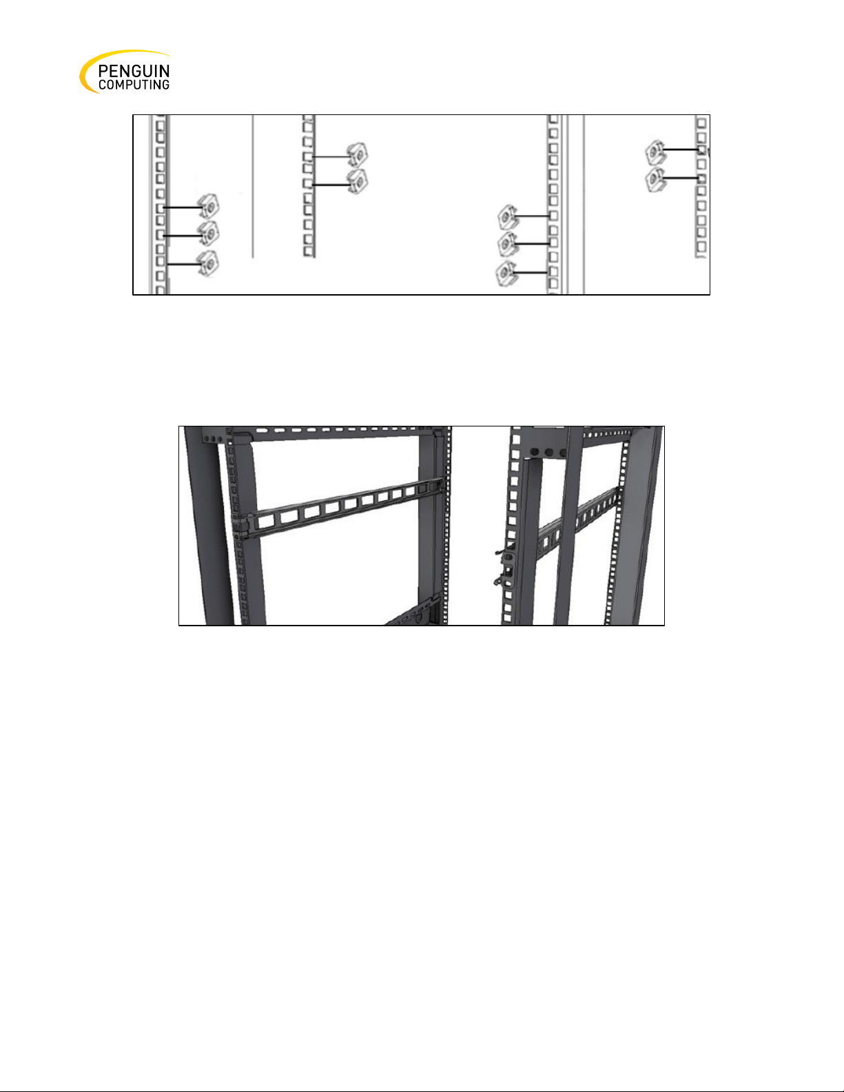
Step 1. Install 10 cage nuts into the desired 1U slots of the rack: 4 cage nuts in the non-extractable
side and 6 cage nuts in the extractable side.
Rev. 1.0 Penguin Computing
Page 26
26
Figure 16: Installing the Cage Nuts
Step 2. Mount both of the outer rails (C+D) into the rack (as shown in the figure below), and then use
8 standard pan-head screws (E) to fix them to the rack. Do not tighten the screws yet.
Figure 17: Mounting the Outer Rails into the Rack
Step 3. If cable accommodation is required, route the power cable and/or Eth cable through either of
the outer rails.
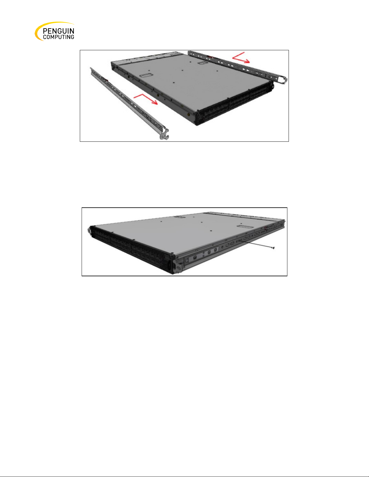
Step 4. Attach the switch to the left and right inner rails (A+B), by gently pushing the switch chassis
pins through the slider key holes, until locking occurs.
Rev. 1.0 Penguin Computing
Page 27
27
Figure 18: Attaching the Inner Rails to the Chassis
Step 5. Secure the chassis in the inner rails by screwing the 2 flat head Phillips screws (F) in the
designated points with a torque of 1.5±0.2 Nm.
Figure 19: Securing the Chassis in the Inner Rails
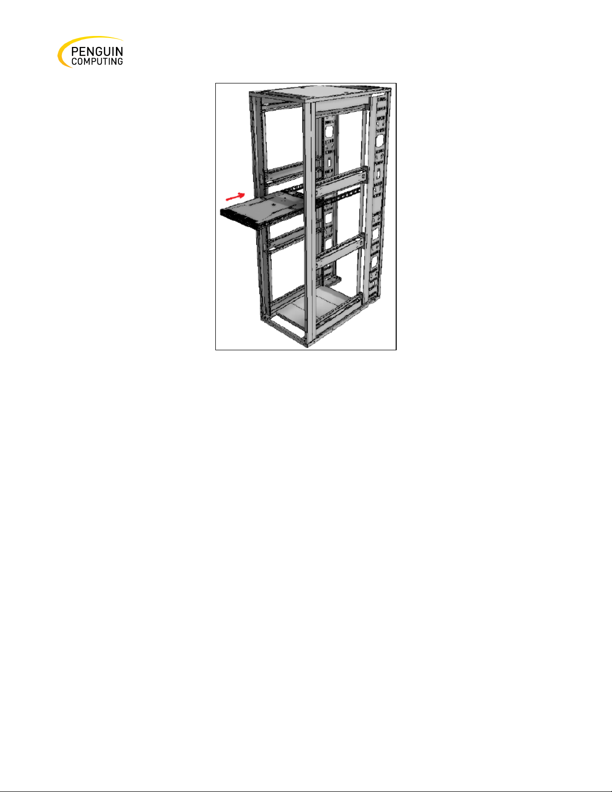
Step 6. Slide the switch into the rack by carefully pushing the inner rails into the outer rails installed
on the rack.
Rev. 1.0 Penguin Computing
Page 28
28
Figure 20: Sliding the Switch into the Rack
Step 7. When fully inserted, fix the switch by closing the remaining 2 screws in the middle and
tightening the 8 screws inserted in Step 2 with a torque of 4.5±0.5 Nm.
Removing the System from the Rack
Follow these steps to remove a unit from the rack:
Step 1. Turn off the system and disconnect it from peripherals and from the electrical outlet.
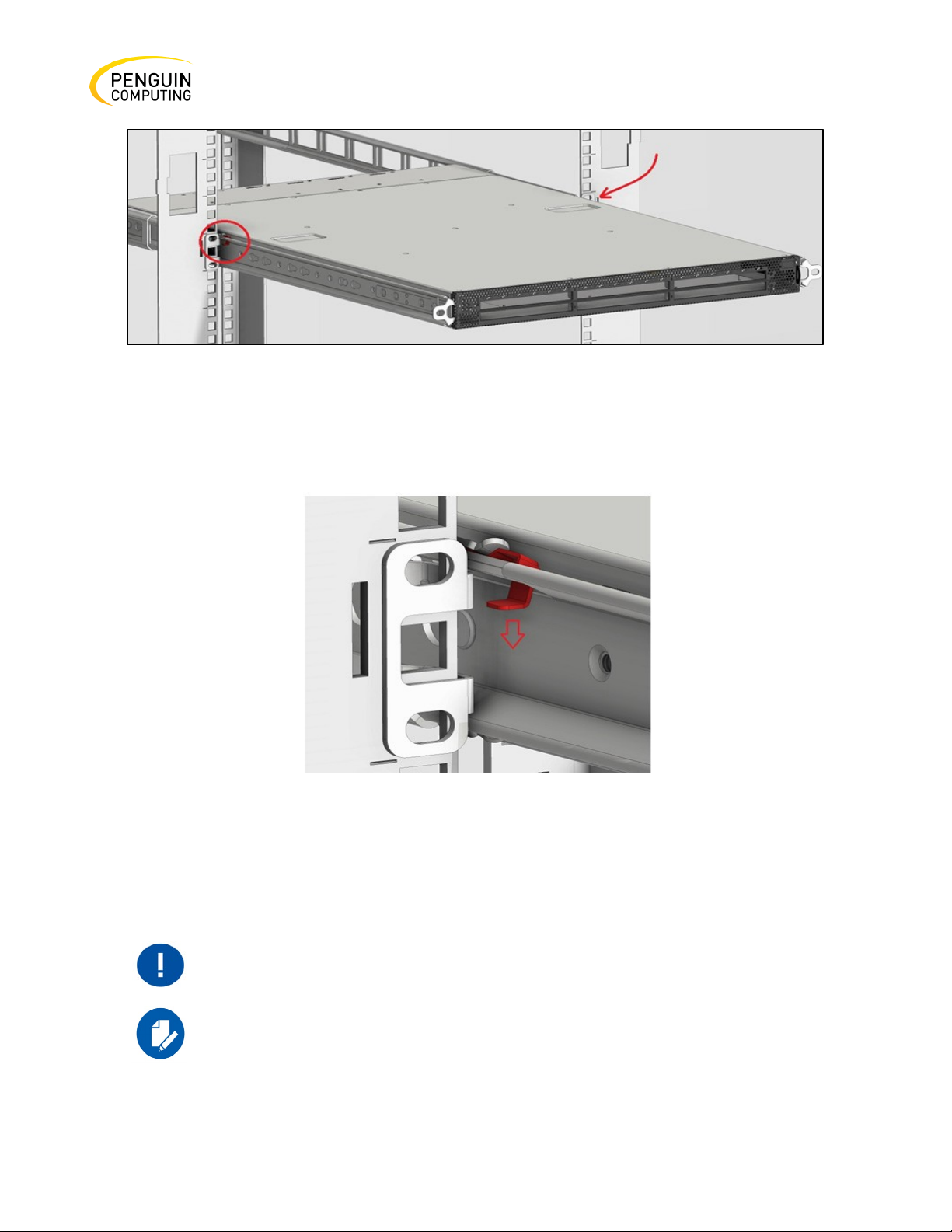
Step 2. Unscrew the two M6 screws securing the front of the inner rails’ ears to the outer rails and to
the rack.
Step 3. Pull the unit out until braking is felt. For safety purposes, the locking mechanism will not allow
a complete removal of the unit at this stage.
Rev. 1.0 Penguin Computing
Page 29
29
Figure 21: Pulling the Unit Outwards
Step 4. Press on the locking spring (appears in red in Figure 24) on both sides simultaneously, and
then continue pulling the unit towards you until it is fully removed.
Figure 22: Locking Mechanism
Static Rail Kit for Arctica 4808xs
At least two people are required to safely mount the system in the rack.
By default, the system is sold with the standard-depth rail kit. The shortdepth rail kit can be supplied upon request.
Rev. 1.0 Penguin Computing
Page 30
30
Penguin PN
Rack Size and Rack Depth Range
10026063
Short (19.7"-23.6" \ 50 to 60 cm)
10026064
Standard (23.6"-31.5" \ 60 to 80 cm)
Table 6: Installation Kit
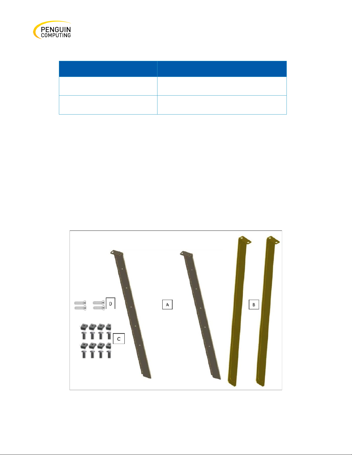
The following parts are included in the static rail kit (see Figure 23: Rack Rail Kit Parts):
• 2x Rack mount rails (A)
• 2x Rack mount blades (B)
• 8x M6 Standard cage nuts¹ ² and 8x M6 Standard pan-head Phillips screws¹ (C)
• 4x Phillips100 DEG F.H TYPE-I ST.ST 6-32 X 1/4 screw with around patch (D).
¹ Other threads are available by special order: M5, 10-32, 12-24
² G-type cage-nut is available by special order.
Figure 23: Rack Rail Kit Parts
Rev. 1.0 Penguin Computing
Page 31
31
Before mounting the system to the rack, select the way you wish to place the system. Pay attention
to the airflow within the rack cooling, connector and cabling options.
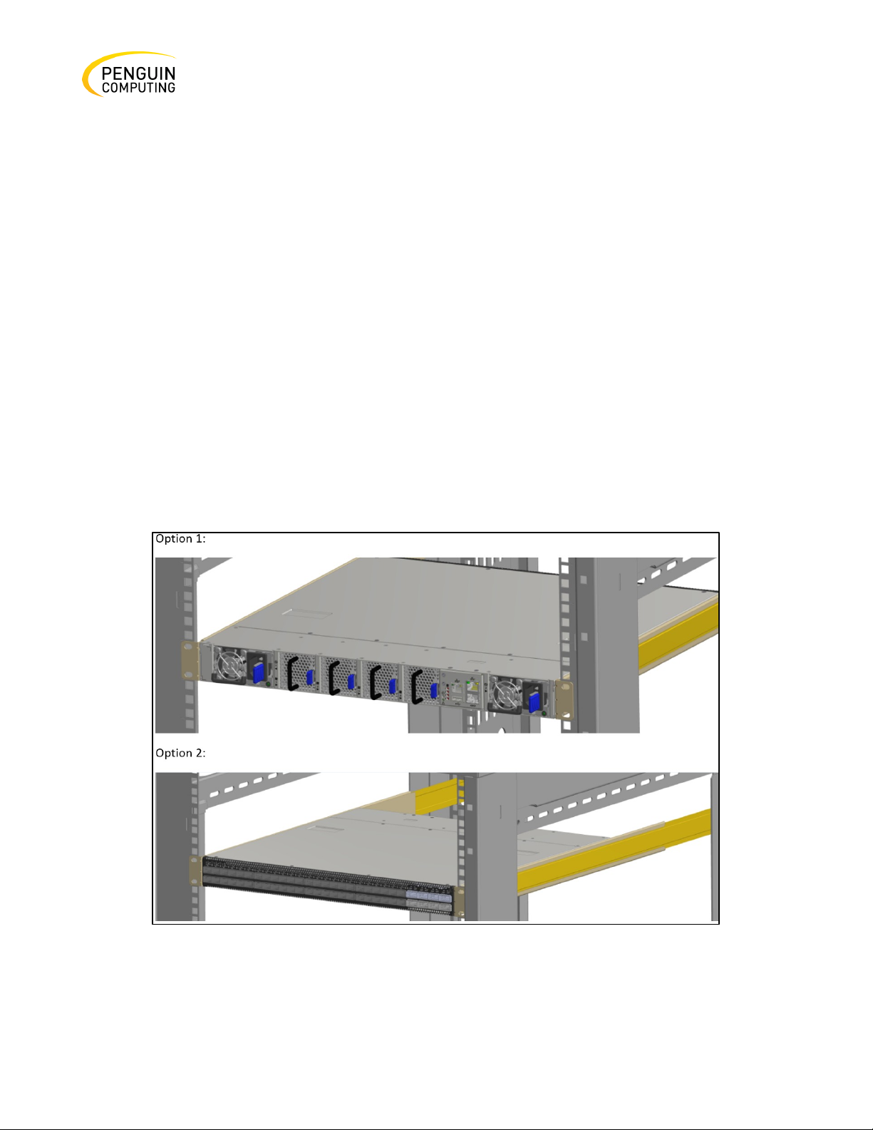
While planning how to place the system, consider the two installation options shown in the figure
below, and review the following points:
• Make sure the system air flow is compatible with your installation selection. It is import- ant
to keep the airflow within the rack in the same direction.
• Note that the part of the system to which you choose to attach the rails (the front panel
direction, as demonstrated in Option 1 or the FRUs direction, as demonstrated in Option 2,
will determine the system’s adjustable side. The system’s part to which the blades are
attached, will be adjacent to the cabinet.
• In case there are cables that cannot bend within the rack, or in case more space is needed for
cable bending radius, it is possible to recess the connector side or the FRU side by 3.5" (8.9
cm), by optional placement of the system’s rails.
• The FRU side is extractable. Mounting the rack blades inverted to the FRU side (Option 2) will
allow you to slide the FRUs, in and out.
Figure 24: Installation Options
Rev. 1.0 Penguin Computing
Page 32
32
Follow these steps:
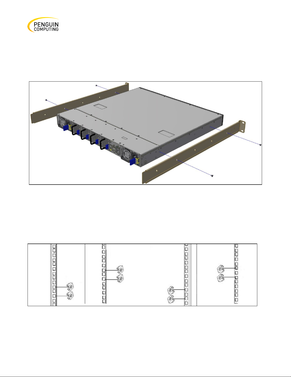
Step 1. Attach the left and right rack mount rails (A) to the switch, and then secure the chassis in the
rails by screwing 2 flat head Phillips screws (D) in the designated points on each side (a total of 4
screws). See the figure below. To tighten the screws, use a torque of 1.5±0.2 Nm.
Figure 25: Attaching the Rails to the Chassis
Step 2. Install 8 cage nuts (C) in the desired 1U slots of the rack: 4 cage nuts in the non-extractable
side and 4 cage nuts in the extractable side. Note that while each rack U (unit) consists of three holes,
the cage nut should be installed vertically with its ears engaging the top and bot- tom holes only. See
the figure below.
Figure 26: Installing the Cage Nuts
Rev. 1.0 Penguin Computing
Page 33
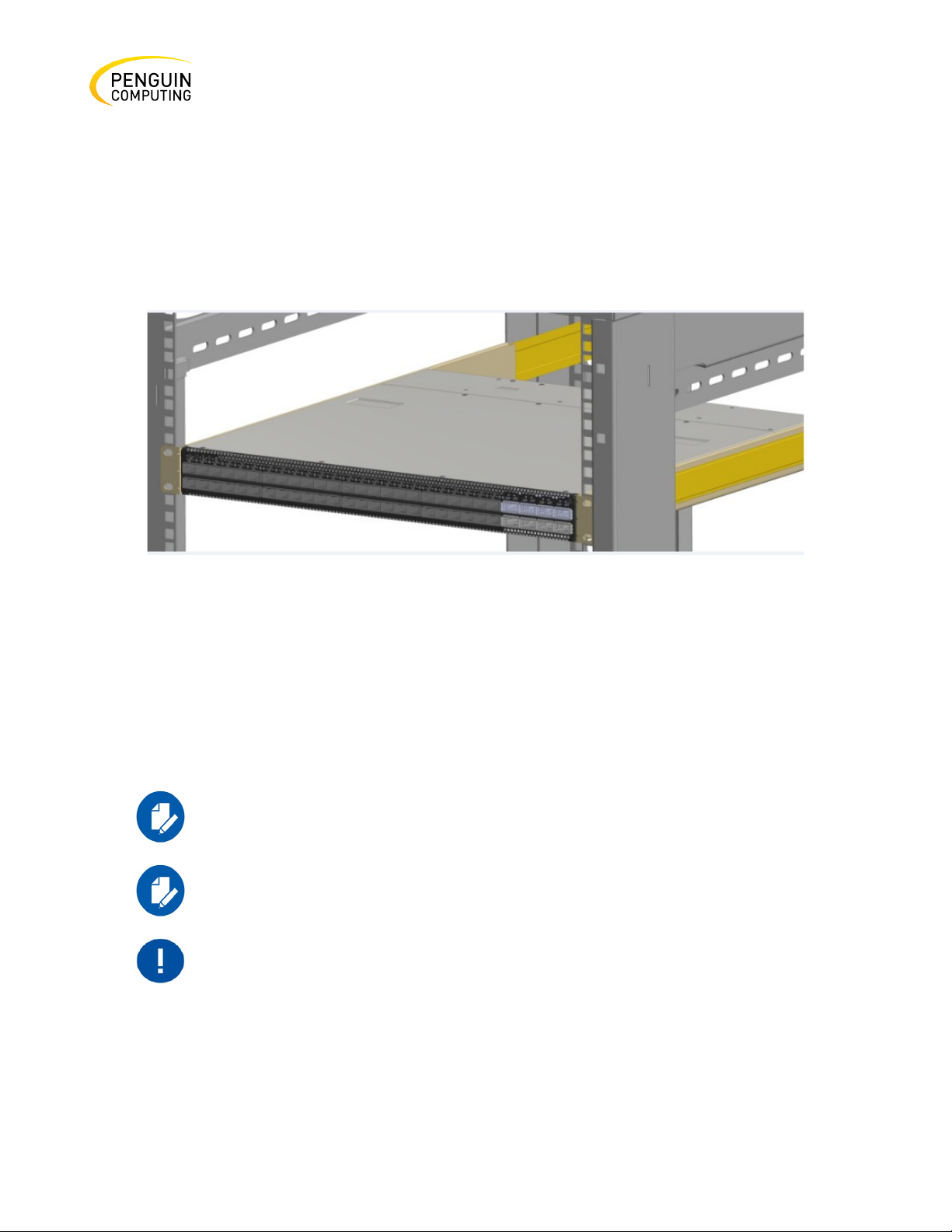
33
For safety, it is necessary that at least two people mount the system in the
rack.
With your installation partner supporting the weight of the system, perform steps 3, 4 and 5:
Step 3. On the rear side of the cabinet, install the two blades (B) in the selected rack unit, using four
M6 screws (C). Do not tighten the screws yet. See Figure 29.
Step 4. Slide the two blades into the left and right rails, and adjust them to fit your rack's depth. Use
four M6 screws (D) to fix the blades into the rack. Do not tighten the screws yet. See Figure 30.
Figure 27: Sliding the Blades in the Rails
Step 5. Secure the system in the rack by tightening the 8 screws inserted in Step 3 and Step 4 with a
torque of 4.5±0.5 Nm.
Side by Side Mounting for Arctica 1600cs Rail Kit
A designated rail kit for the Arctica 1600cs systems can be purchased
separately.
This section is relevant to short-depth systems that permit this type of
installation.
Rev. 1.0 Penguin Computing
Page 34

34
Penguin PN
Rack Size and Rack Depth Range
10026065
Rack installation kit for 1600cs short depth
Table 7: Installation Kit
1U switches permits installation of one or
two switches side-by-side into standard
depth racks.
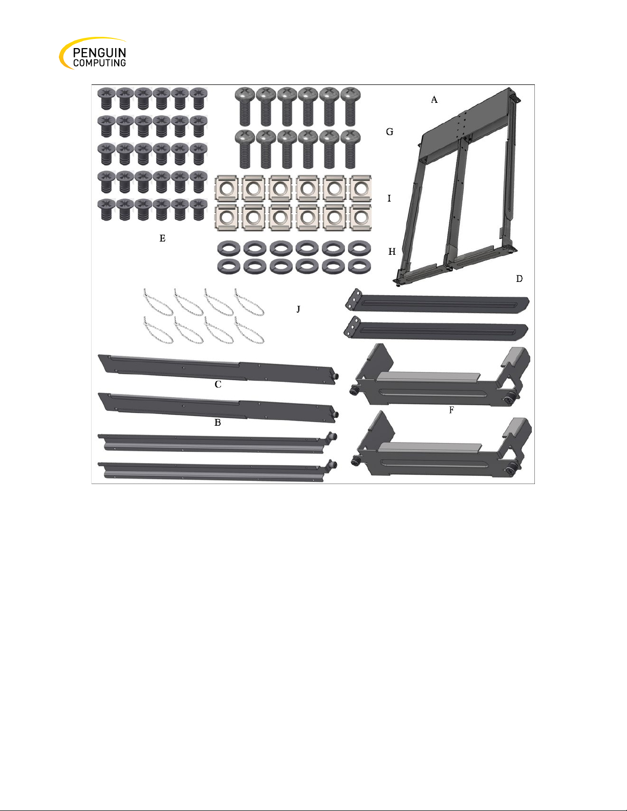
The following parts are included in the rail kit (see Figure 28 below):
•
1 metal frame for two systems (A)
•
2 system mounting blades with 8 screw holes - the kit contains enough rails to install 2 systems
(B)
•
2 system mounting blades with 7 screw holes - the kit contains enough rails to install 2 systems
(C)
•
2 frame rail slides (D)
•
30 flat head 4-40 screws - the kit contains enough screws to install 2 systems (E)
•
2 blank covers (F)
•
10 (+2 spare units) M6 pan head screws (G)
•
10 (+2 spare units) M6 spring washers (H)
•
10 (+2 spare units) M6 spring steel cage nuts (I)
•
6 (+2 spare units) cable-ties (J)
Rev. 1.0 Penguin Computing
Page 35
35
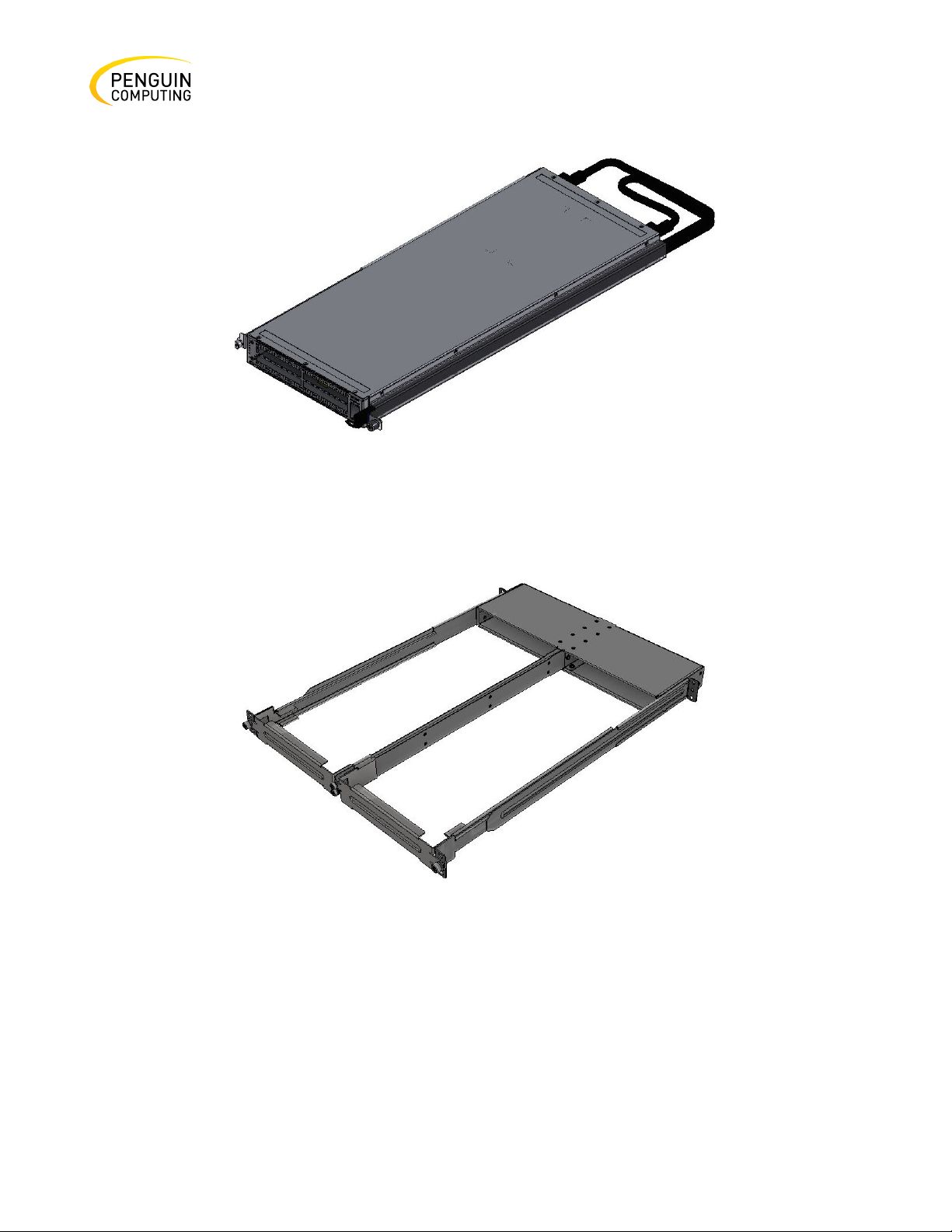
Figure 28: Rack Rail Kit Parts
Before mounting the system to the rack, choose how you want to place the system. Pay attention to
the airflow within the rack cooling, connector, and cabling options.
• The installation kits come with enough system mounted rails and flat head screws to install
two systems.
• The two system metal frames will fit into racks with from 23.6” (600mm) to 31.5” (800mm)
space between the vertical supports.
• You may install your system in either the right or in the left part of the metal frame.
• The following instructions apply to installation in the right part. For installation in the
frame’s left part, follow the same instructions, while replacing “right” with “left”, and vice
versa.
Rev. 1.0 Penguin Computing
Page 36
36
While pairing the cables, make sure the cables are paired in symmetry to
the switch, in order to avoid damaging the cables.
Follow these steps:
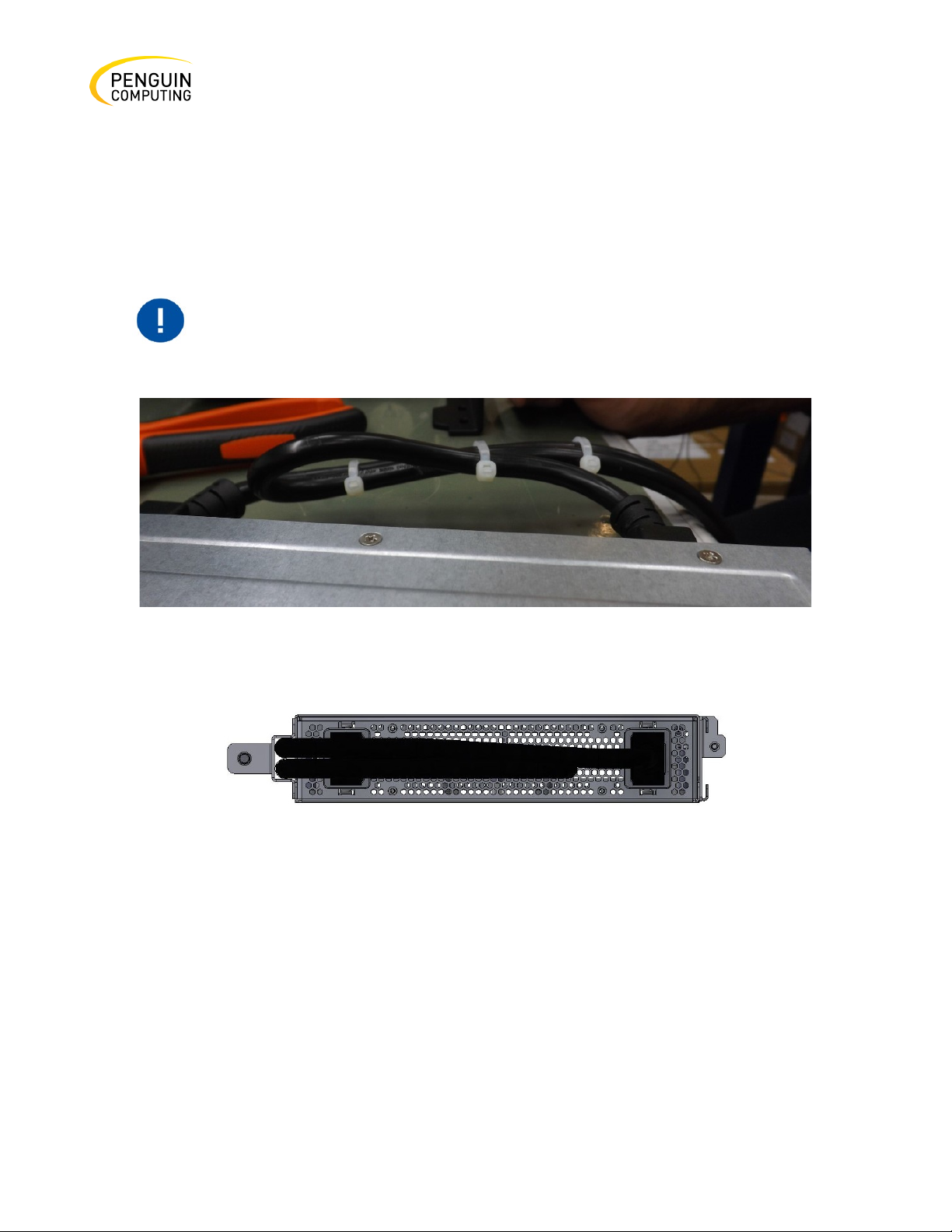
Step 1. Insert the SE (single ended) plugs to the dedicated inlets in the system’s rear panel.
Step 2. Carefully position the SE (single ended) cables one on top of the other, then use three cable
ties to pair them together, as shown in the figure.
Figure 29: Coupling the Cables with Cable-ties
Figure 30: Coupled Cables - Rear View
Step 3. Place the coupled cables in the designated area within the right flat blade (the blade with 7
screw holes) as shown in the figure below.
Rev. 1.0 Penguin Computing
Page 37
37
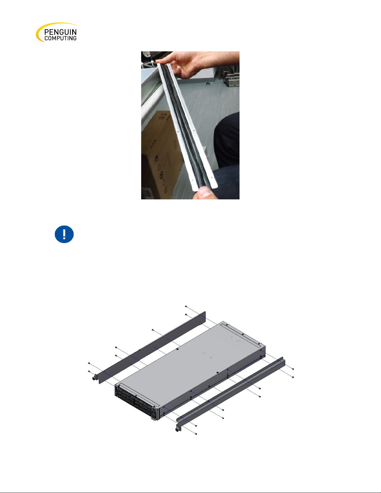
In the next step, you will be attaching the rails to the chassis, before doing
excessive pressure, as it can damage the cables.
Figure 31: Cables within the Rail
that, make sure the cables are laid properly within them. Avoid using
Step 4. While holding the cables together in the blade rail with one hand, use your other hand to
secure the blades to the chassis. Screw in the right blade with eight 4-40 flathead screws, and the left
blade with seven 4-40 flathead screws. The recommended torque is 0.49-0.54 Nm.
Figure 32: Attach the blades to the system
Rev. 1.0 Penguin Computing
Page 38
38
Figure 33: Attached Rail with Threaded Cables - Top View
Step 5. Slide the two frame slides into the dedicated rails in the metal frame. See the figure below.
Figure 34: Sliding the Frame Sliders into the Rails
Step 6. Place the frame in the cabinet, then install ten cage nuts in the desired 1U slots of the rack:
three cage nuts in the front part of each cabinet post, and two cage nuts in the rear part of each
cabinet post.
Rev. 1.0 Penguin Computing
Page 39
39
Do not remove both of the blank covers at the same time. When no
Figure 35: Installing the Cage Nuts
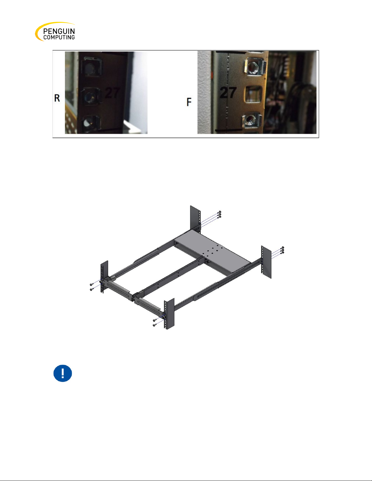
Step 7. Attach the frame to the rack by using ten-spacer cage nut to adapt the square openings in the
vertical support, and then screw ten M6 pan head screws—four in the front part of the rack, and six
in its rear part. The recommended torque is 6.55-7.35 Nm. See the figure below.
Figure 36: Attaching the Frame to the Rack
system is installed, at least one of them should be present to support the
frame’s partition.
Rev. 1.0 Penguin Computing
Page 40
40
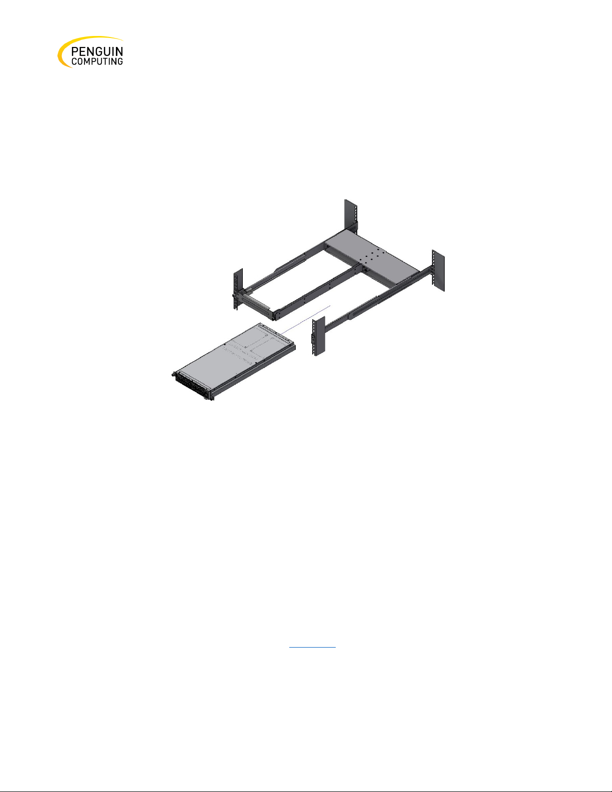
Step 8. Remove the blank cover from the selected slot in the frame and mount the system by sliding
its mounting blades into the frame. Repeat this step to install an additional system in the other side
of the frame, if needed.
Step 9. Tighten the capture nuts to secure the system in the frame. The recommended torque on the
right screw is 3.0-3.36 Nm while on the left screw recommended torque is 0.89-0.98 Nm.
Figure 37: Sliding the System’s Blades in the Rails
Cable Installation
All cables can be inserted or removed with the unit powered on.
To insert a cable, press the connector into the port receptacle until the connector is firmly seated.
The LED indicator, that corresponds to each data port will light when the physical connection is
established. When a logical connection is made, the relevant port LED will turn on.
To remove a cable, disengage the locks and slowly pull the connector away from the port receptacle.
The LED indicator for that port will turn off when the cable is unseated.
For more information about port LEDs, refer to Port LEDs.
Rev. 1.0 Penguin Computing
Page 41
41
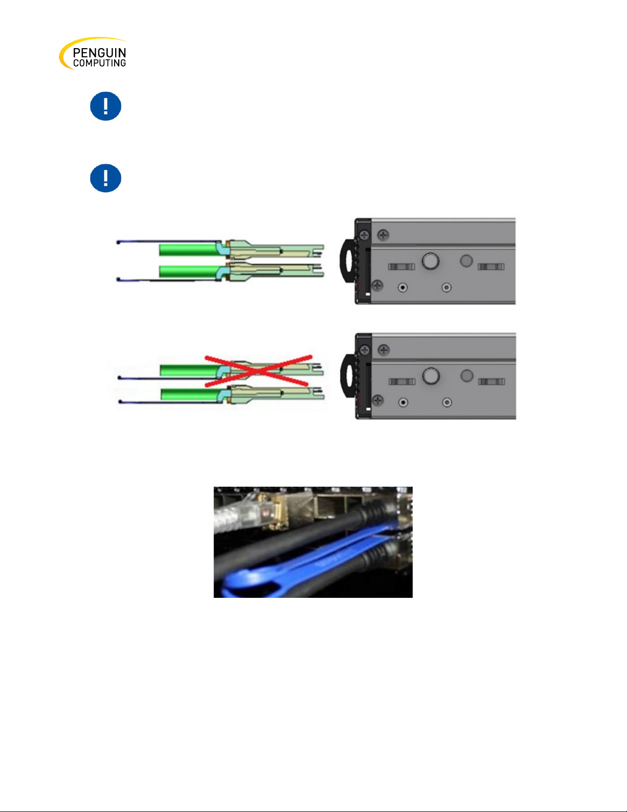
Do not force the cable into the cage with more than 40 newtons / 9.0
The Arctica 4808xs system includes ports of different types. Figure 43 does
not apply to the SFP+ ports. See the figure below.
pounds / 4kg force. Greater insertion force may cause damage to the cable
or to the cage.
Figure 38: Arctica 3200cs and Arctica 1600cs Cable Orientation
Figure 39: Arctica 4808xs Cable Orientation
Breakout Cables and Adapters
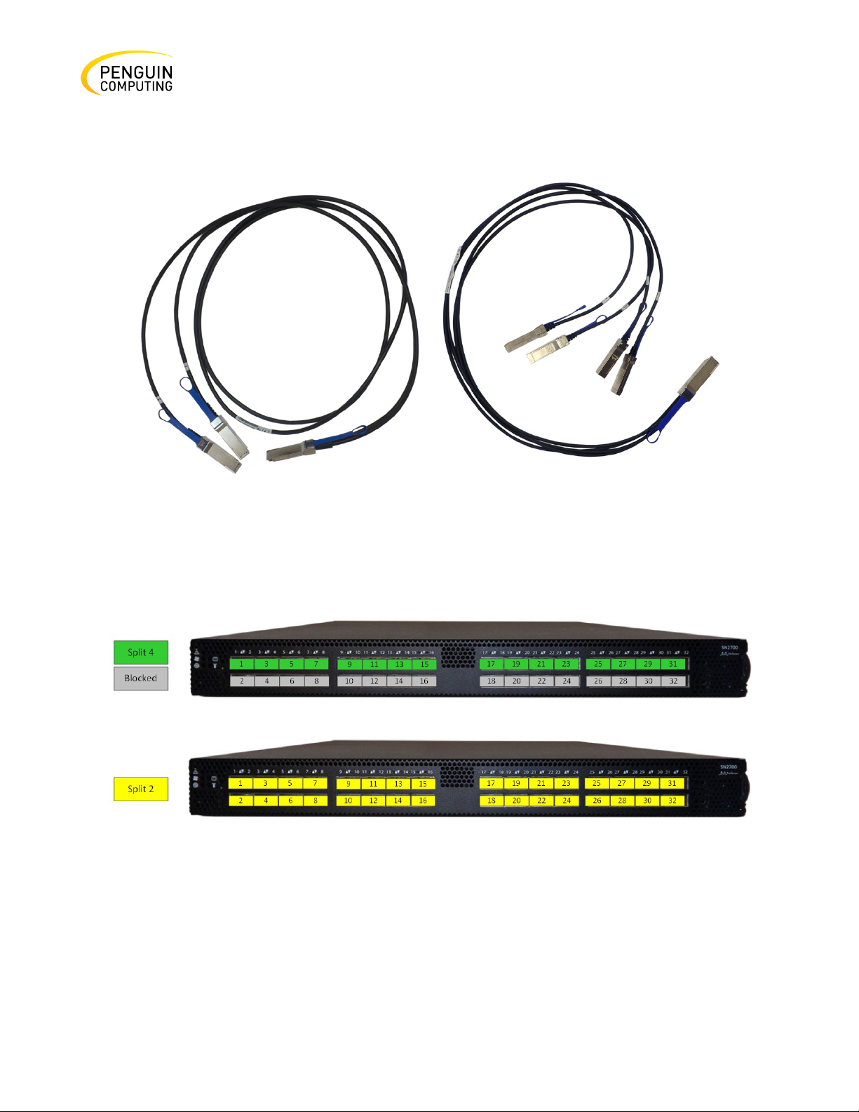
A 100GbE port can be split to two 50GbE ports, or to four (or less) 25GbE ports, using a breakout
cable.
Rev. 1.0 Penguin Computing
Page 42
42
Splitting a 100GbE QSFP28 port to 4 separate 25GbE ports (using a breakout cable) disables (unmaps)
the 100GbE port below it. See the figures below.
Figure 40: Breakout or Fanout
Arctica 3200cs Splitting Options
Figure 41: Arctica 3200cs Splitting Options
The top QSFP28 ports marked in green can be split into 4 SFP28 ports, each. The bottom QSFP28
ports (gray) are blocked when the upper ports are in split mode. All QSFP28 ports marked in yellow
can be split to 2 SFP28 ports.
Rev. 1.0 Penguin Computing
Page 43
43
The system platform will automatically power on when AC power is
It may take up to five minutes to turn on the system. If the System Status
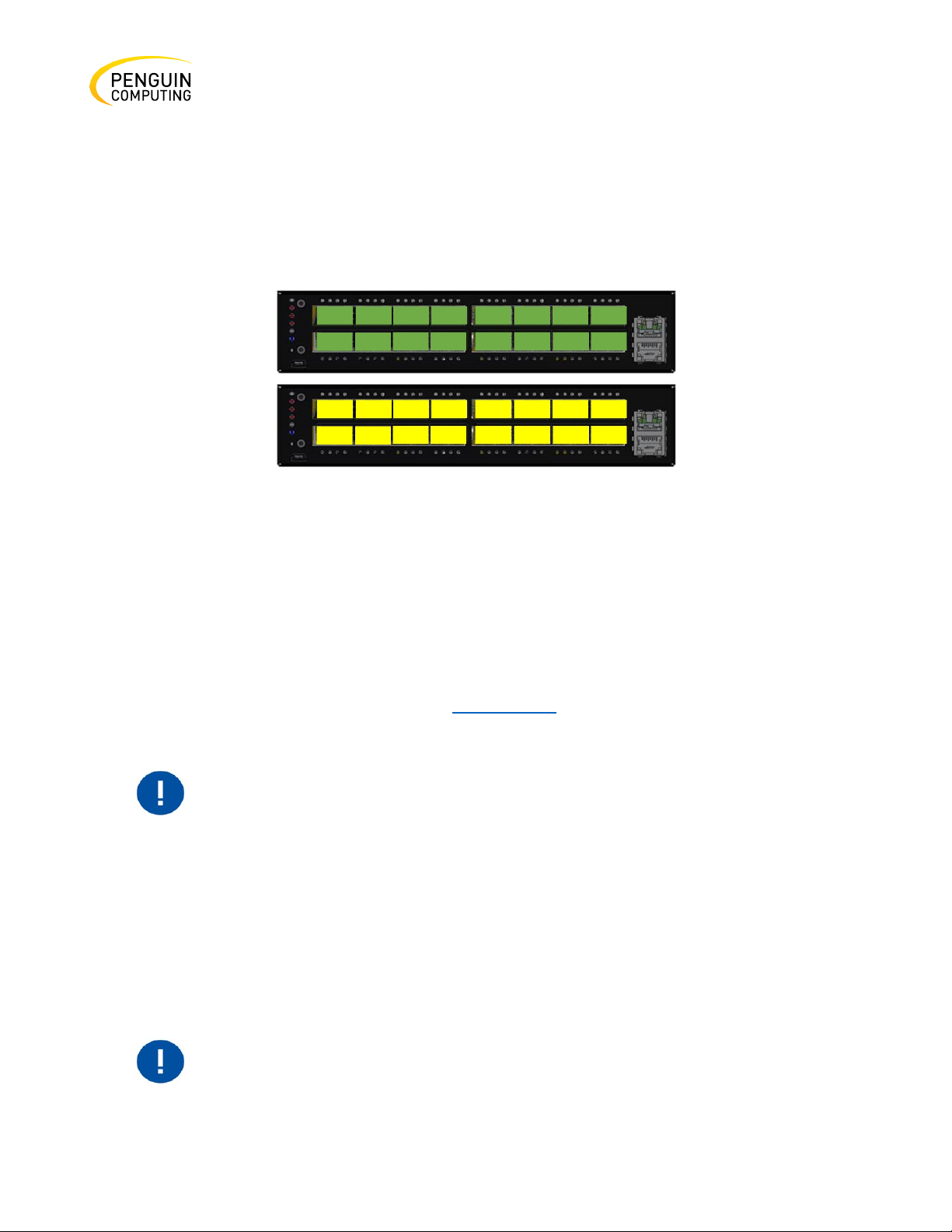
Arctica 4808xs Splitting Options
The top QSFP28 ports - 49,51,53,55 (green) can be split into 4 SFP28 ports each. All QSFP28 ports can
be split into two QSFP28 ports.
The bottom QSFP28 ports - 50,52,54,56 (gray) are blocked when the upper ports are in split mode.
Figure 42: Arctica 1600cs Splitting Options
All QSFP28 ports cam be split. Each port can be split to 4xSFP28 (10/25G) or 2xQSFP28 (50G) ports
each. There are no blocking requirements.
Initial Power On
The input voltage of each system is given in the Specifications chapter. The power cords should be
standard 3-wire AC power cords including a safety ground and rated for 15A or higher.
Step 1. Plug in the first power cable.
Step 2. Plug in the second power cable.
Step 3. Wait for the System Status LED to turn green.
applied. There is no power system. Check all boards, power supplies, and
fan tray modules for proper insertion before plugging in a power cable.
LED shows red after five minutes, unplug the system and call your Penguin
Computing representative for assistance.
Rev. 1.0 Penguin Computing
Page 44
44
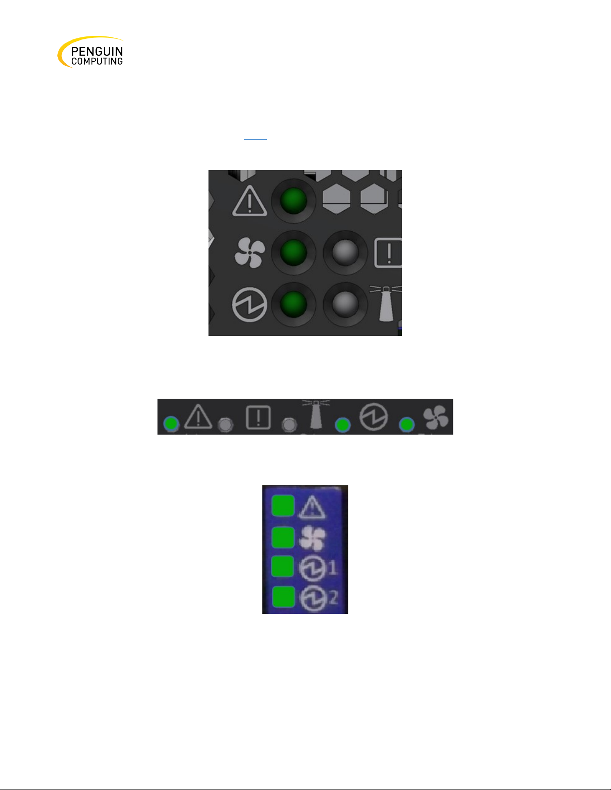
Step 4. Check the System Status LEDs and confirm that all of the LEDs show status lights consistent
with normal operation (initially flashing, and then moving to a steady color) as shown in the figure
below. For more information, refer to LEDs.
Figure 43: System Status LEDs 5 Minutes
After Power On in Arctica 3200cs
Figure 44: System Status LEDs 5 Minutes After Power On
Figure 45: System
Status LEDs 5 Minutes
After Power On
Rev. 1.0 Penguin Computing
Page 45

45
After inserting a power cable and confirming the green System Status LED
The following information does not apply to the Arctica 1600cs series. The
Ensure that the power supply unit that you are NOT replacing is showing
all green, for both the power supply unit and System Status LEDs.
Power supply units have directional air flows similar to the fan module.
For power supply unit air flow direction, refer to Fans.
Risk of electric shock and energy hazard. The two power supply units are
independent.
Disconnect all power supplies to ensure a powered down state inside of
the switch platform.
Figure 46: Two Power Inlets - Electric Caution Notifications
light is on, make sure that the Fan Status LED shows green.
If the Fan Status LED is not green, unplug the power connection and check
that the fan module is inserted properly and that the mating connector of
the fan unit is free of any dirt and/or obstacles. If no obstacles were found
and the problem persists, call your Penguin Computing representative for
assistance.
FRU Replacements
Arctica 1600cs systems include two non-replaceable power supply units
and four non-replaceable fan units.
Power Supply
Arctica systems that are equipped with two replaceable power supply units work in a redundant
configuration. Either unit may be extracted without bringing down the system.
The fan module airflow must coincide with the airflow of all of the power
supply units. If the power supply unit airflow direction is different from the
fan module airflow direction, the system’s internal temperature will be
affected.
Rev. 1.0 Penguin Computing
Page 46
46
Do not attempt to insert a power supply unit with a power cord connected
to it.
The power supply slots of Arctica 4808xs should not be left empty for
more than 5 minutes.
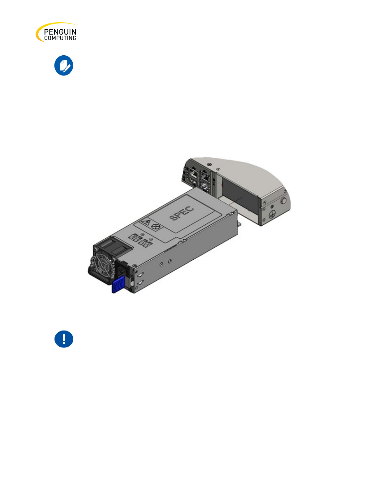
Step 1. Remove the power cord from the power supply unit.
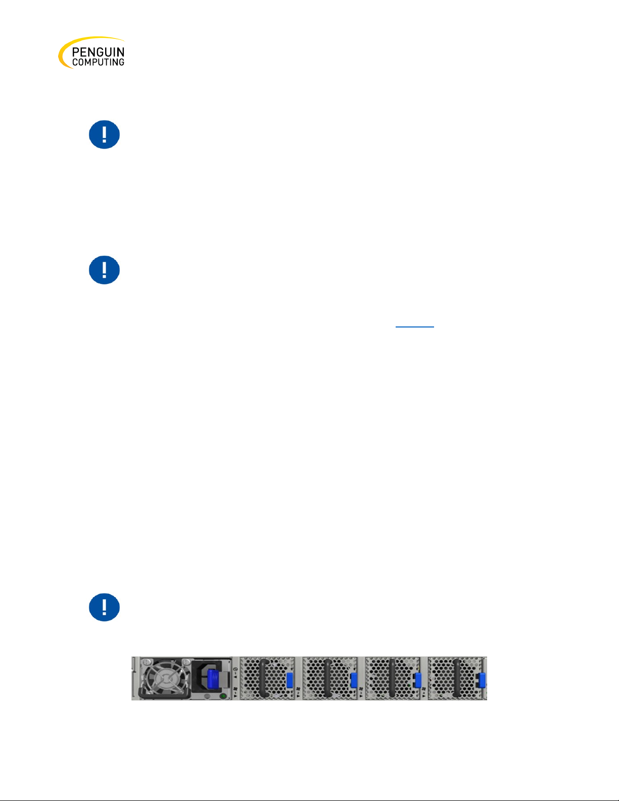
Step 2. Grasping the handle with your hand, push the latch release with your thumb while pulling the
handle outward. As the power supply unit unseats, the power supply unit status LEDs will turn off.
Step 3. Remove the power supply unit.
Figure 47: PS Unit Pulled Out
To insert a power supply unit:
Step 1. Make sure the mating connector of the new unit is free of any dirt and/or obstacles.
Step 2. Insert the power supply unit by sliding it into the opening, until a slight resistance is felt.
Step 3. Continue pressing the power supply unit until it seats completely. The latch will snap into
place, confirming the proper installation.
Step 4. Insert the power cord into the supply connector.
Rev. 1.0 Penguin Computing
Page 47
47
The green power supply unit indicator should light. If it does not, repeat
the whole procedure to extract the power supply unit and re-insert it.
Ensure that the fans have the air flow that matches the model number. An
For power supply unit air flow direction, refer to Air flow.
The green Fan Status LED should light. If not, extract the fan unit and
the system before attempting to debug the system.
Step 5. Insert the other end of the power cord into an outlet of the correct voltage.
Fans
The system can fully operate if one fan FRU is dysfunctional or missing. Failure of more than one fan
is not supported.
To remove a fan unit:
Step 1. Grasping the handle with your right hand, push the latch release with your thumb
while pulling the handle outward. As the fan unit unseats, the fan unit status LEDs will turn
off.
Step 2. Remove the fan unit.
To insert a fan unit:
Step 1. Make sure the mating connector of the new unit is free of any dirt and/or obstacles.
Step 2. Insert the fan unit by sliding it into the opening until slight resistance is felt. Continue
pressing the fan unit until it seats completely.
air flow opposite to the system design will cause the system to operate at
a higher (less than optimal) temperature.
Rev. 1.0 Penguin Computing
reinsert it. After two unsuccessful attempts to install the fan unit, power off
Figure 48: Fan Module Latches
Page 48

48
Model Family
Ports
Maximum High Power Support
Arctica 3200cs
1, 2, 31, 32
4.5Wa
Arctica 4808xs
1,2,47,48
2.5W
49, 50, 55, 56
4.5Wa
Arctica 1600cs
1, 2, 15, 16
4.5Wa
Interfaces
Supported Interfaces
The systems support the following interfaces:
•
Data interfaces - Ethernet
•
10/100/1000 MbE speed rates
•
USB port (mini USB in 1600cs)
•
RS232 Console port
•
RJ45 management interface(s)
•
Reset button
•
Status and Port LEDs
In order to review the full configuration options matrix, refer to Table 2: Management Interfaces,
PSUs and Fans.
Data Interfaces
The data interfaces use QSFP28 connectors. The full list of interfaces per system is provided in Table
1: Speed and Switching Capabilities. Each QSFP28 port can be connected with a QSFP28 cable or
connector for 25/40/50/56/100GbE, or 1/10/25GbE when connecting through QSFP28 to SFP28
adapters, hybrid or split cables. The systems offer High Power/LR4 transceivers support (up to 3.5W)
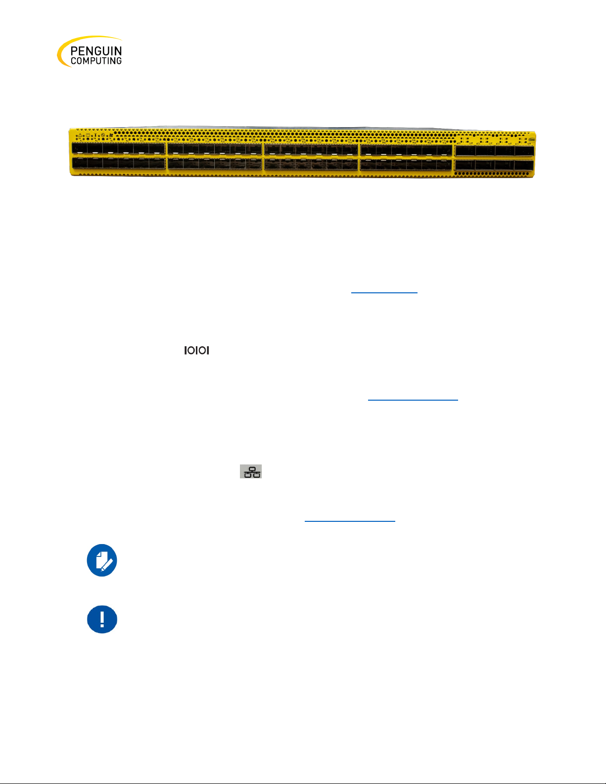
in all QSFP28 ports. Some QSFP28 ports support 4.5W transceivers, as detailed in the following table:
Table 8: High Power/LR4 Transceivers Support
a
4.5W high power modules are supported on MLNX-OS from version 3.6.3004 onwards.
Rev. 1.0 Penguin Computing
Page 49
49
The SFP+ ports in 4808xs support Level II (up to 1.5W) transceivers.
Figure 49: Using 4.5W Modules on Ports 49, 50, 55, 56 in Arctica 4808xs
Speed
Ethernet speed must be set manually. The system’s ports can be manually configured to run at
speeds ranging from 10GbE to 100GbE (for more details, see Specifications.
RS232 (Console)
The port labeled Console is an RS232 serial port on the back side of the chassis in Arctica
3200cs and Arctica 4808xs, and on the front side in Arctica 1600cs. It is used for initial configuration
and debugging. Upon first installation of the system, you need to connect a PC to this interface and
configure network parameters for remote connections. Refer to FRU Replacements to view the full
procedure.
Management
The RJ45 Ethernet ports labeled MGT provide access for remote management. The management
ports are configured with auto-negotiation capabilities by default (100MbE to 1000GbE). The
management ports’ network attributes (such as IP address) need to be pre-configured via the RS232
serial console port or by DHCP before use. Refer to FRU Replacements to view the full procedure.
In the Arctica 1600cs systems there is only one MGT port.
Ensure you use only FCC compliant Ethernet cables.
Rev. 1.0 Penguin Computing
Page 50

50
Do not use a sharp pointed object such as a needle or a push pin for
pressing the reset button. Use a flat object to push the reset button.
USB
The USB interface is USB 2.0 (mini USB in Arctica 1600cs) compliant (USB 1.0 is not supported). The
connector comes in a standard USB shape.
To view the full matrix of the USB configuration options, refer to Table 2: Management Interfaces,
PSUs and Fans.
Do not use excessive force when inserting or extracting the USB disk to
and from the connector.
Reset Button
The reset button is located on the rear side of the system next to the fan status LEDs in Arctica
3200cs and Arctica 4808xs, and on the front side in Arctica 1600cs. This reset button requires a tool
to be pressed.
To reset the system and the CPU of its management board, push the reset button and keep it pressed
for up to 15 seconds.
To reset the system, the CPU of its management board, and the “admin” password, push the reset
button and keep it pressed for at least 15 seconds.
Status and Port LEDs
See “LEDs” in the next section.
LEDs
LED Notifications
Rev. 1.0 Penguin Computing
Page 51
51
Symbol
Name
Description
Normal Conditions
System Status LED
Shows the health of the
Green/Flashing
Fan Status LED
Shows the health of the fans.
Green
Power supply units LEDs
Shows the health of the
Green
Bad Port LED
Lights up when a symbol
Off
Unit Identifier LED
Lights up on command
Off or blue when
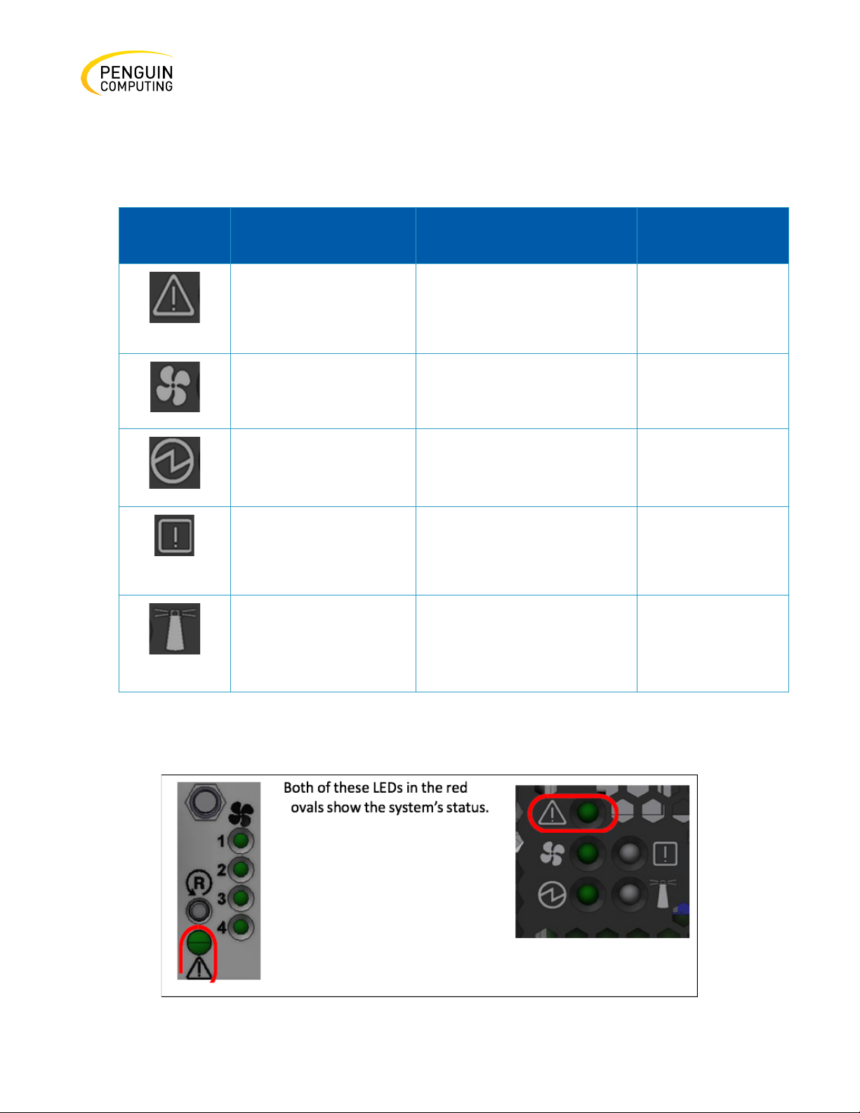
The system LEDs are an important tool for hardware event notification and troubleshooting.
Table 9: LEDs Symbols
System Status LED
system.
power supply units.
error is detected on one of
the ports.
through the CLI.
green when
booting
identifying a port
Rev. 1.0 Penguin Computing
Page 52
52
It may take up to five minutes to turn on the system. If the System Status
Computing representative for assistance.
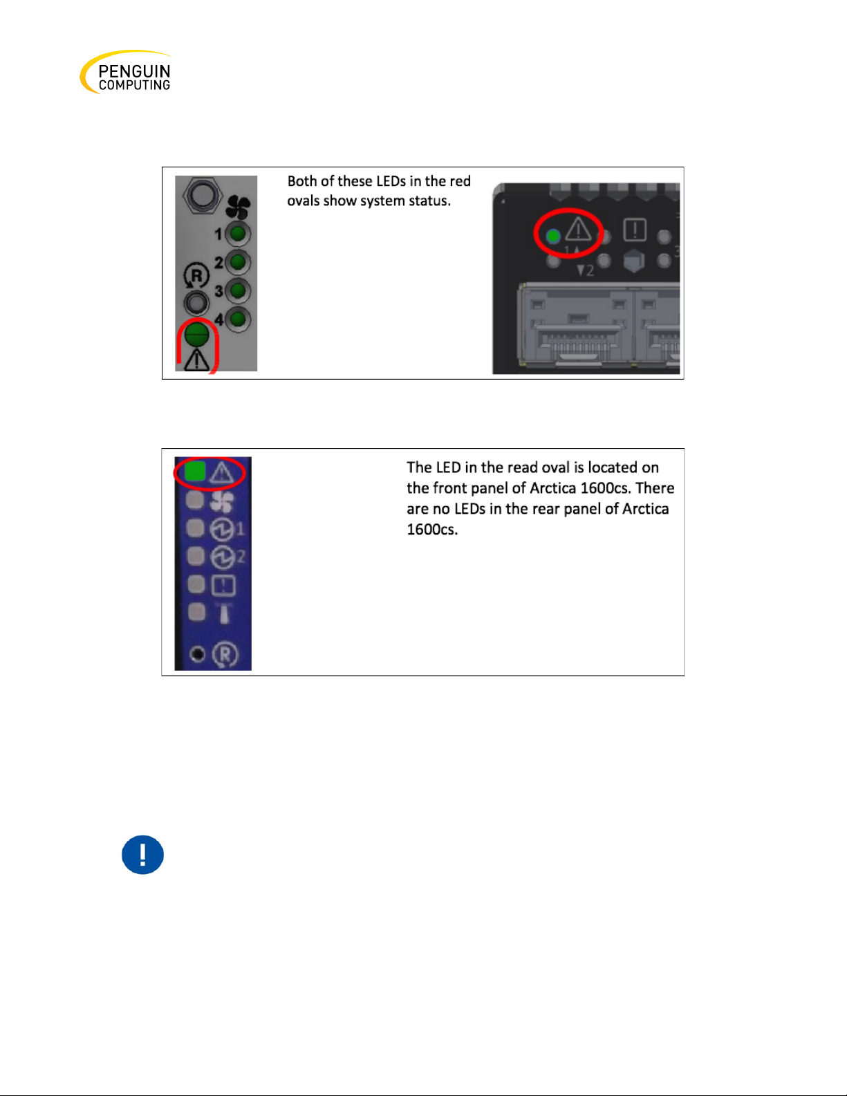
Figure 50: System Status LEDs - Front and Rear Sides in Arctica 3200cs
Figure 51: System Status LEDs - Front and Rear Sides in Arctica 4808xs
Figure 52: System Status LED in Arctica 1600cs
Both of the System Status LEDs (front and back, if exist) supply identical information.
LED shows red after five minutes, unplug the system and call your Penguin
Rev. 1.0 Penguin Computing
Page 53
53
LED Behavior
Description
Action Required
Solid Green
The system is up and running
N/A
Flashing Green
The system is booting up.
Wait up to five minutes for the end
Solid Red
Major error has occurred. For
If the System Status LED shows red
Table 10: System Status LED Assignments
nor- mally.
of the booting process.
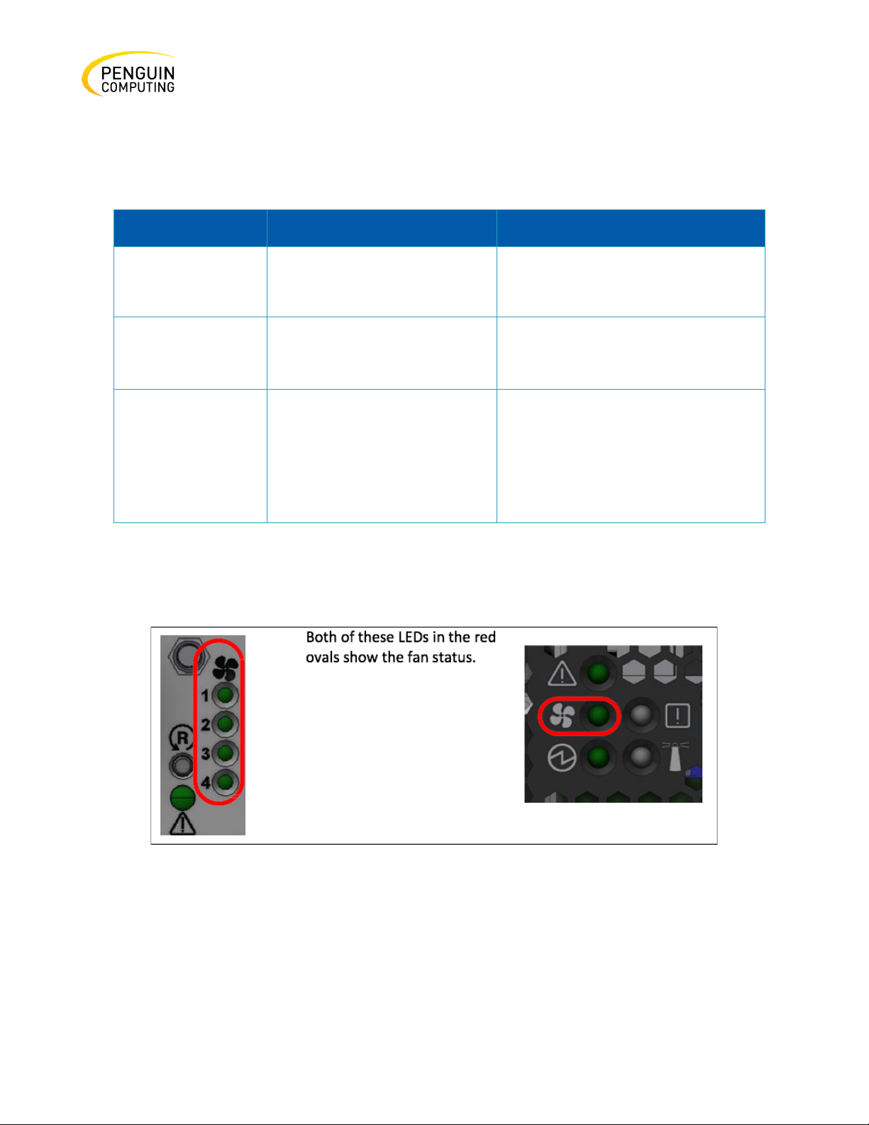
Fan Status LED
example, corrupted firmware,
sys- tem is overheated etc.
five minutes after starting the
system, unplug the system and call
your Penguin Computing
representative for assistance.
Figure 53: Fan Status LED in Arctica 3200cs - Front and Rear Sides
Rev. 1.0 Penguin Computing
Page 54
54
LED
Behavior
Description
Action Required
Solid Green
All fans are up and running.
N/A
Solid Red
Error, one or more fans are not
The faulty FRUs should be
Off
System boot
N/A
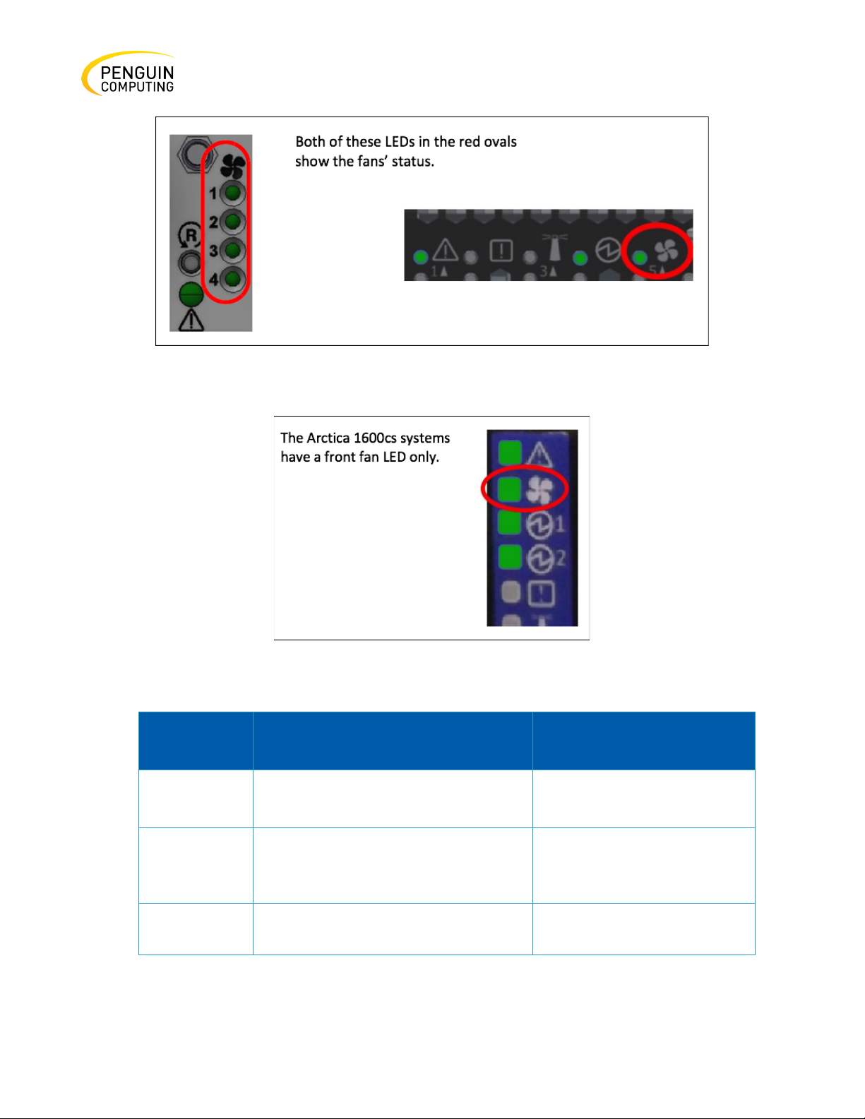
Figure 54: Fan Status LED in Arctica 4808xs - Front and Rear Sides
Figure 55: Fan Status LED in Artica 1600cs
operating properly.
replaced.
Rev. 1.0 Penguin Computing
Page 55
55
LED
Behavior
Description
Action Required
Solid Green
A specific fan is operating.
N/A
Solid Red
A specific fan unit is missing or not
The fan unit should be
Off
System boot
N/A
Risk of Electric Shock!
The following information does not apply to the Arctica 1600cs systems. In
below.
The table below does not apply to the Arctica 1600cs systems.
operating properly.
With the fan module removed, power pins are accessible within the
module cavity. Do not insert tools or body parts into the fan module
cavity.
replaced.
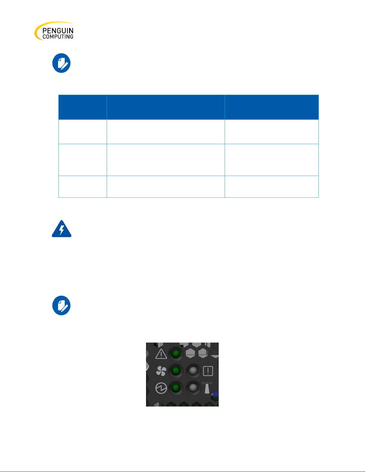
Power Supply Status LEDs
Rev. 1.0 Penguin Computing
these systems, the power supply units are non-replaceable, and there is a
designated LED for each unit in the system’s front panel. See the figures
Figure 56: Power Status LED
Page 56
56
LED
Behavior
Description
Action Required
Solid Green
All plugged (one or two) power
supplies are running normally.
N/A
Solid Red
PSU is faulty or disconnected
Make sure the AC cable is
Off
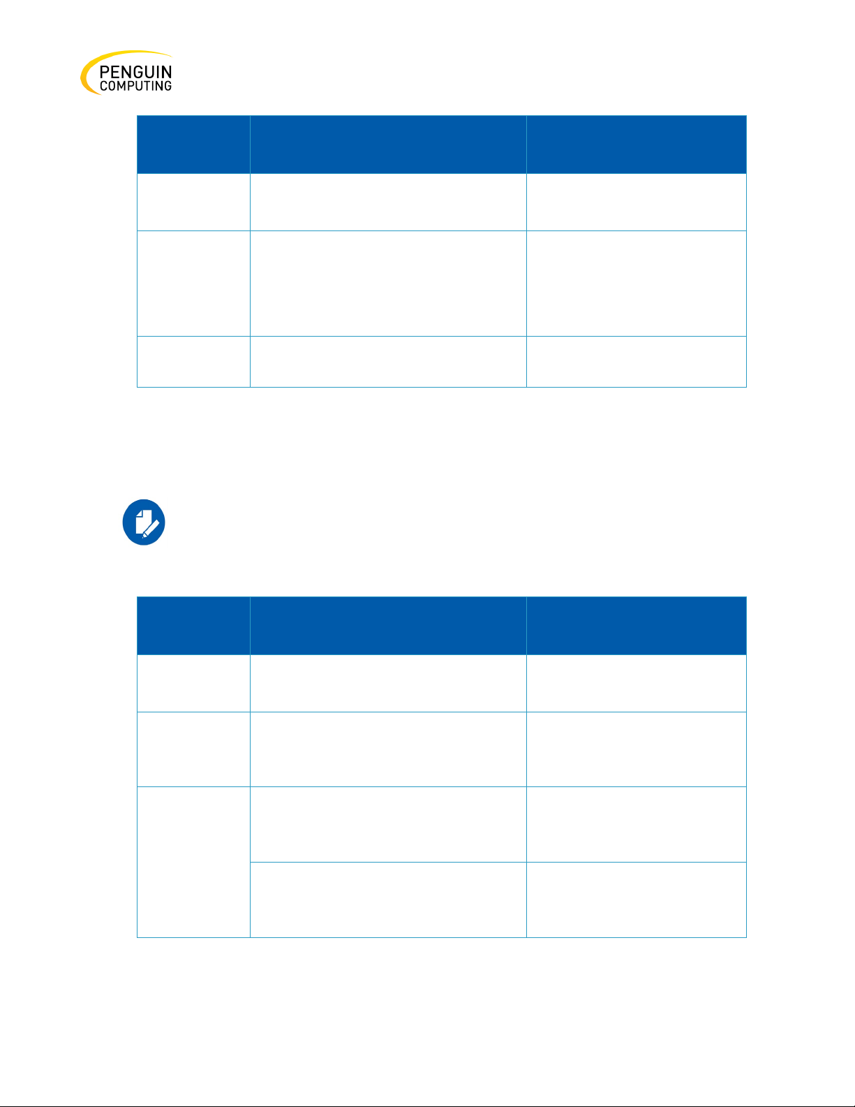
N/A
N/A
There are two power supply inlets in the system (for redundancy). The system can operate with only
one power supply connected. In case the power supply is an FRU, a second power supply unit can be
added to support hot-swap ability. Each power supply unit has a single 2 color LED on the right side of
the unit, that indicates the status of the unit.
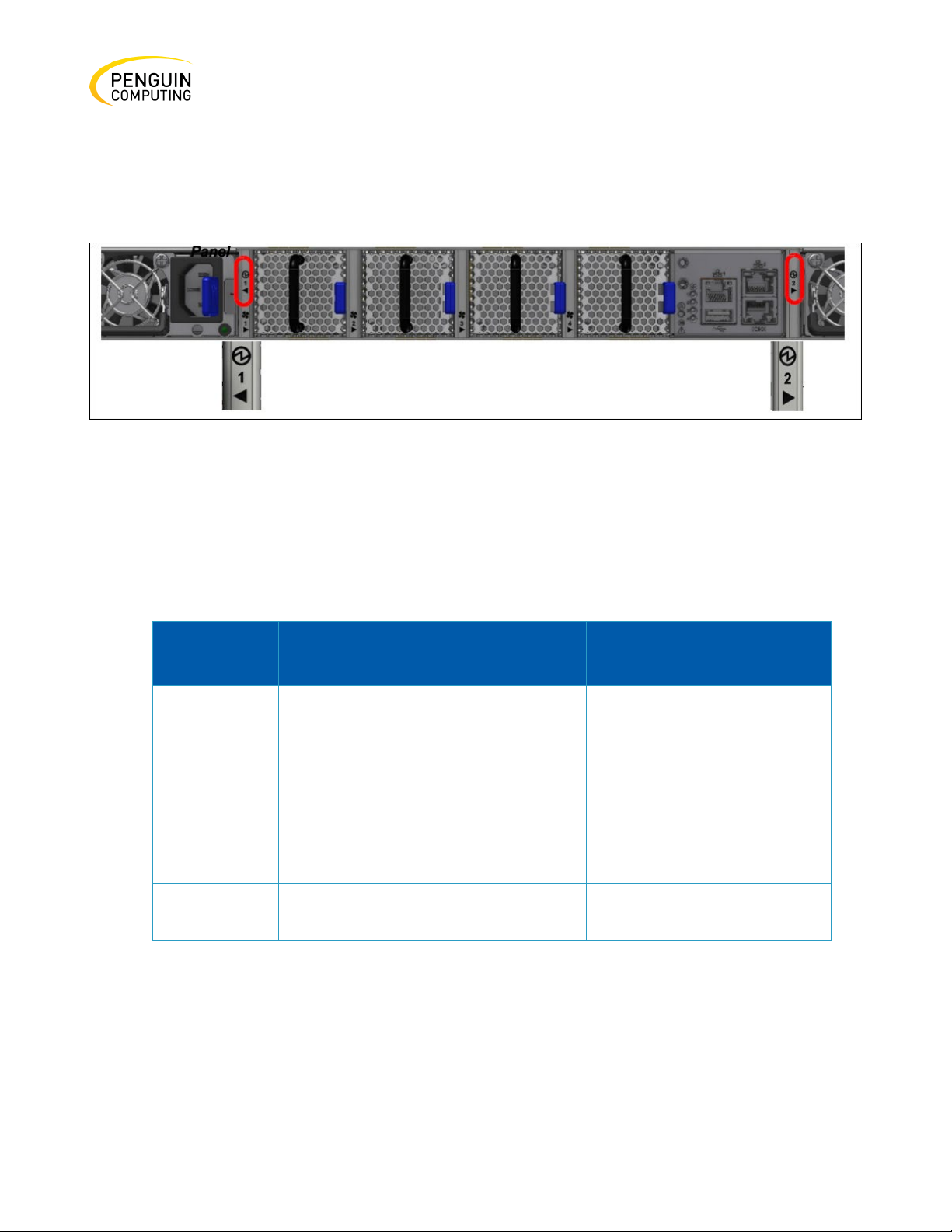
Figure 57: Arctica 3200cs and Arctica 4808xs Rear Side
The primary power supply (PS) unit is located on the left side, and the secondary unit is located on
the right side.
Table 11: Power Supply Unit Status Front LED Assignments for Arctica 3200cs and Arctica 4808xs
plugged in and active. If the
problem resumes, the FRUs
might be faulty, and should
then be replaced.
Rev. 1.0 Penguin Computing
Page 57
57
LED
Behavior
Description
Action Required
Solid Green
Power supply is running normally.
N/A
Solid Red
PSU is faulty or disconnected
Make sure the AC cable is
Off
PSU not present
N/A
LED
Behavior
Description
Action Required
Solid Green
The PSU is running normally.
N/A
Flashing
AC present / Only 12VSB on (PSU off)
Call your Penguin Computing
Amber
AC cord unplugged or AC power lost
has AC input power.
Plug in the AC cord of the
PS failure (including voltage out of
Check voltage. If OK, call your
representative for assistance.
plugged in and active. If the
problem resumes, the PSU
might be faulty.
The power supply status LEDs on the rear side of the system (in Arctica 3200cs and Arctica 4808xs
only) are located on the PSUs themselves. Each PSU has one LED of its own
Green
The table below does not apply to the Arctica 1600cs systems.
or PSU in Smart-on state.
while the second power supply still
range and power cord disconnected).
representative for assistance.
faulty PSU.
Penguin Computing
Rev. 1.0 Penguin Computing
Page 58

58
LED
Behavior
Description
Action Required
Flashing
Power supply warning events where
Call your Penguin Computing
Off
No AC power to all power supplies.
No AC power to all power
LED
Behavior
Description
Action Required
Flashing
Error, one or more ports have
Check symbol error counters
Off
No symbol errors have been received
N/A
Amber
the power supply continues to
representative for assistance.
operate; high temp, high power, high
current, slow fan.
supplies.
Bad Port LED
The Bad Port LED indicator is used to indicate symbol errors in one or more system ports. Table 22
shows the bad port status LED assignment.
Table 12: Bad Port LED Assignments: Bad Port LED Assignments
Amber
Rev. 1.0 Penguin Computing
received symbol errors.
Possible causes are:
•
Bad cable
•
Bad connection
•
Bad connector
in last few seconds (normal
condition).
on the system UI to identify
the ports. Replace the cable
on these ports.
Page 59
59
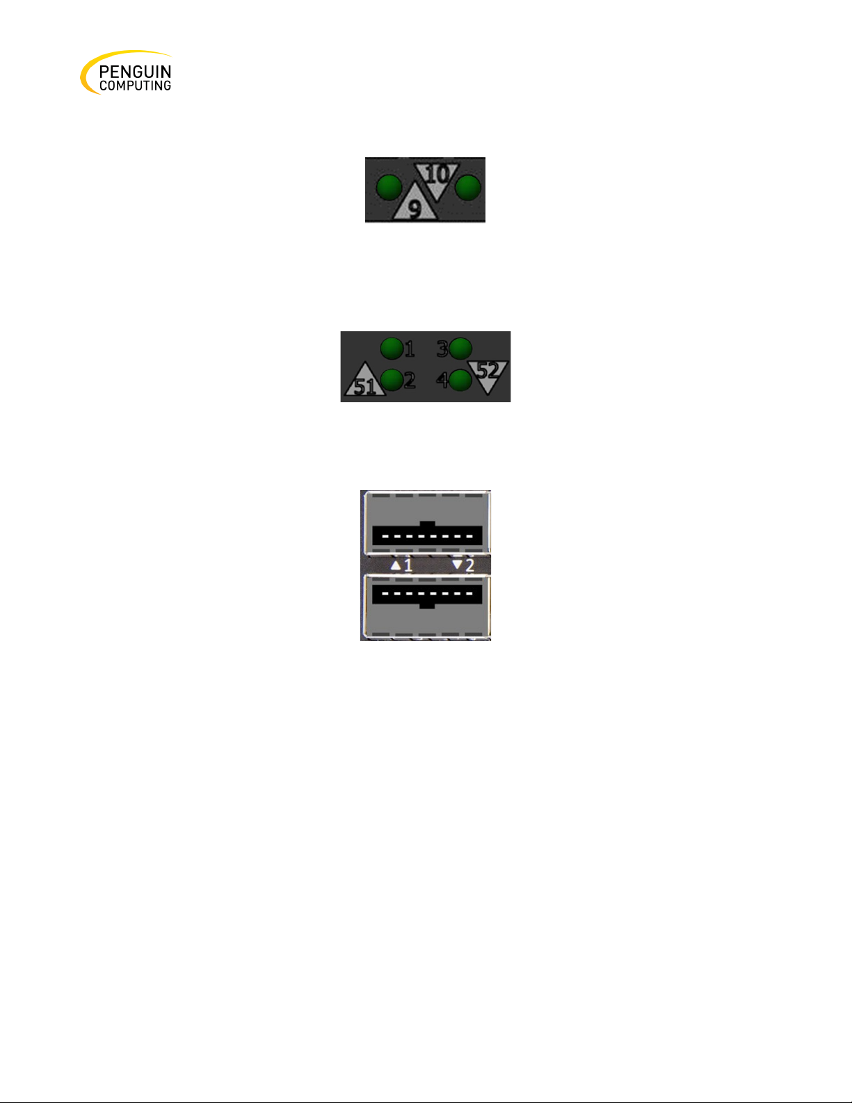
Port LEDs
Figure 58: Arctica
4808xs SFP+ Port LEDs
Figure 59: Arctica 4808xs
QSFP28 Port LEDs
Figure 60: Arctica
1600cs Port LEDs
In the Arctica 4808xs systems, the status of each pair of adjacent QSFP28 ports is indicated by four
LEDs, as shown in the picture above:
•
While the bottom LEDs signify the port status in regular condition, the upper LEDs operate
only when the port is split.
•
When one port is split to two, a connection of 100GbE can be utilized in its adjacent port.
•
When one port is split to four, it adjacent port is cancelled.
•
If the ports run at a 100GbE/40GbE speed each, the two lower LEDs (2 and 4) will light green.
•
If the ports run at a 50GbE speed each, the left LEDs (1 and 2) will light green for the upper
port, and the right LEDs (3 and 4) will light green for the lower port.
•
If the ports run at a 25GbE/10GbE speed each, all LEDs may light green, according to the
selected lane.
Rev. 1.0 Penguin Computing
Page 60
60
LED
Behavior
Description
Action Required
Solid Green
Link is up with no traffic.
N/A
Flashing
Link is up with traffic.
N/A
Flashing
A problem with the link.
Check the cable, then replace
Off
Link is down.
Check the cable.
Green
Amber
it if necessary.
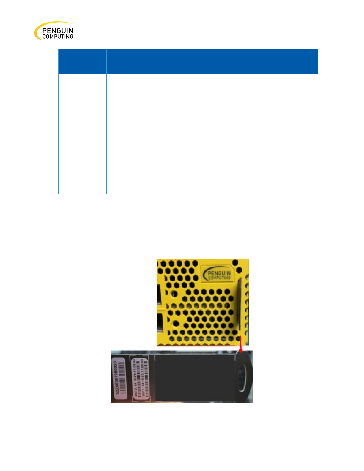
Inventory Information
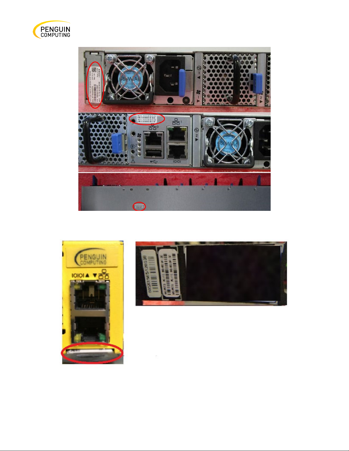
System inventory parameters (such as Serial Number, Part Number, GUID and MAC address) can be
extracted from the inventory pull-out tab on the lower right side of the front panel. In some systems,
there is no pull-out tab, and the information is provided on labels in several locations.
Rev. 1.0 Penguin Computing
Figure 61: Arctica 3200cs Pull-out Tab
Page 61
61
Figure 62: Arctica 4808xs Inventory Information Illustration
Figure 63: Arctica 1600cs Pull-out Tab
Rev. 1.0 Penguin Computing
Page 62

62
Software Management
There are three thermal threshold definitions for the switch device which impact the overall switch
system operation state:
•
Warning – 105°C: On managed systems only: When the device crosses the 100°C threshold, a
Warning Threshold message will be issued by the management SW, indicating to system
administration that the switch has crossed the Warning threshold. Note that this temperature
threshold does not require nor lead to any action by hardware (such as switch shutdown).
•
Critical – 120°C: When the device crosses this temperature, the firmware will automatically
shut down the device.
•
Emergency – 130°C: In case the firmware fails to shut down the device upon crossing the
Critical threshold, the device will auto-shutdown upon crossing the Emergency (130°C)
threshold.
Rev. 1.0 Penguin Computing
Page 63

63
Problem Indicator
Symptoms
Cause and Solution
LEDs
System Status LED is
Cause: OS software did not boot
System Status LED is red
Cause:
Fan Status LED is red
Cause: Possible fan issue.
PSU Status LED is red
Cause: Possible PSU issue.
Troubleshooting
Troubleshooting Instructions
Table 13: Troubleshooting
blinking for more than 5
minutes
properly, and only firmware is running.
Solution: Connect to the system via the
console port, then check the software
status. You might need to contact a FAE if
the OS software did not load properly.
• Critical system fault (CPU error, bad
firmware)
• Over Temperature Solution:
• Check environmental conditions
(room temperature).
Solution: Check that the FAN is fully
inserted and nothing blocks the airflow
Replace the FAN FRU if needed (possible
in Arctica 3200cs and 4808xs only).
Rev. 1.0 Penguin Computing
Solution: Check/replace the power cable
Replace the PSU if needed (possible in
Arctica 3200cs and 4808xs only)
Page 64
64
Feature
Value
Mechanical
Size:
Mounting: 19” Rack mount
Weight:
Speed: 10/25/40/50/100GbE per port
Connector cage: 32 QSFP28
Environmental
Temperature:
Humidity:
Altitude: 3050m
Noise level: 71.6 dB(A)
Regulatory
Safety/ EMC: CB, TUV, CE, FCC, VCCI
Specifications
Arctica 3200cs Series
Table 14: Arctica 3200cs Specifications
Standard - 1.72” (H) x 16.84” (W) x27” (D), 43.8mm (H) x 427.83mm (W) x
686.8mm (D)
1 PSU: 10.23kg, 2 PSUs: 11.1kg
Operational: 0° to 40°C
Non-Operational: -40° to 70°C
Operational: 10% - 85% non-condensing Non-Operational: 10% - 90% noncondensing
Rev. 1.0 Penguin Computing
Page 65

65
Feature
Value
RoHS6
Power
Input Voltage: 100-127VAC; 50/60Hz 3.5A; 200-240 50/60Hz 2.9A/ 192-
Global Power Consumption: 40GbE Models -
Max power with optical cables (assuming 3.5W per port): 398W
Main Devices
CPU: Intel x86 1.40GHZ Dual Core
Switch: Mellanox Spectrum™
Memory:
Throughput
3.2Tb/s
288VDC (not certified)
Max power with optical cables (assuming 2W per port): 308.5W
100GbE Models -
Typical power with passive cables (ATIS): 150W
PCIe: 4x Gen2.0
8GB DDR3 RAM, 32GB SSD
Rev. 1.0 Penguin Computing
Page 66
66
Feature
Value
Mechanical
Size:
Mounting: 19” Rack mount
Weight:
Speed: 10/25/40/50/100GbE per QSFP28 port
Connector cage: 48 SFP+ and 8 QSFP28
Environmental
Temperature:
Humidity:
Altitude: 3050m
Noise level: 70.9 dB(A)
Regulatory
Safety/ EMC: CB, TUV, CE, FCC, VCCI
RoHS6
Arctica 4808xs Series
Table 15: Arctica 4808xs Specifications
43.9mm (H) x 438mm (W) x 394mm (D)
1.72"(H) x 17.24"(W) x 15.5"(D)
1 PSU: 10.23kg, 2 PSUs: 11.1kg
Operational: 0° to 40°C
Non-Operational: -40° to 70°C
Operational: 10% - 85% non-condensing Non-Operational: 10% - 90% noncondensing
Rev. 1.0 Penguin Computing
Page 67

67
Feature
Value
Power
Input Voltage: 100-127VAC; 50/60Hz 3.5A; 200-240 50/60Hz 2.9A/ 192-
Global Power Consumption: 40GbE Models -
1.5W per each SFP28 port): 362W
Main Devices
CPU: Intel x86 1.40GHZ Dual Core
Switch: Mellanox Spectrum™
Memory:
Throughput
2 Tb/s
288VDC (not certified)
Max power with optical cables (assuming 2W per each QSFP28 port, and
1W per each SFP28 port): 295.1
100GbE Models -
Typical power with passive cables (ATIS): 165W
Max power with optical cables (assuming 3.5W per each QSFP28 port, and
PCIe: 4x Gen2.0
8GB DDR3 RAM, 32GB SSD
Rev. 1.0 Penguin Computing
Page 68
68
Feature
Value
Mechanical
Size:
Mounting: 19” Rack mount
Weight:
4.540kg
Speed: 10/25/40/50/100GbE per port
Connector cage: 16 QSFP28
Environmental
Temperature:
Humidity:
Altitude: 3050m
Noise level: 73.7 dB(A)
Regulatory
Safety/ EMC: CB, TUV, CE, FCC, VCCI
RoHS6
Power
Input Voltage: 100-127VAC 50/60Hz 4.5A; 200-240 50/60Hz 2.9A
Arctica 1600cs Series
Table 16: Arctica 1600cs Specifications
43.8mm (H) x 200mm (W) x 508mm (D)
1.72" (H) x 7.87" (W) x 20" (D)
Operational: 0° to 40°C
Non-Operational: -40° to 70°C
Operational: 10% - 85% non-condensing
Non-Operational: 10% - 90% non-condensing
Rev. 1.0 Penguin Computing
Page 69

69
Feature
Value
Global Power Consumption: 40GbE Models -
Main Devices
CPU: Intel x86 2.40GHZ Quad Core
Switch: Mellanox Spectrum™
Memory:
Throughput
3.2 Tb/s
Max power with optical cables (assuming 2W per each QSFP28 port, and
1W per each SFP28 port): 295.1
100GbE Models -
Typical power with passive cables (ATIS): 94.3W
Max power with optical cables (assuming 3.5W per each QSFP28 port, and
1.5W per each SFP28 port): 248.6W
PCIe: 4x Gen2.0
SDRAM: 8GB DDR3L 1600 MT/s SO-DIMM
Storage: 16GB Dual Channel MLC M.2-SATA SSD
Rev. 1.0 Penguin Computing
Page 70

70
Penguin PN
Part Description
10026062
Rack installation kit for 1U systems to be mounted into short or
MTEF-KIT-S
Rack installation kit for standard depth 1U systems to be
10026064
Rack installation kit for 1U wide systems to be mounted into
10026063
Rack installation kit for 1U wide systems to be mounted into
10026065
Rack installation kit for Arctica 1600cs short depth 1U switches,
standard depth racks
10026066
460W AC Power Supply w/ rear to front air flow
10026067
460W AC Power Supply w/ front to rear air flow
10026523
Harness RS232 2M cable – DB9 to RJ-45
10026524
Power cord Type C13-C14
10026068
Fan module w/rear to front airflow
10026069
Fan module w/front to rear airflow
Appendix A: Accessory & Replacement Parts
Table 17: OPNs for Replacement Parts
standard depth racks
mounted into standard depth racks
short depth racks
standard depth racks
allows installation of one or two switches side-by-side into
Rev. 1.0 Penguin Computing
Page 71

71
Support the weight of the system when you remove the
screws so that the system does not fall.
Appendix B: Disassembly and Disposal
Disassembly Procedure
To disassemble the system from the rack:
1. Unplug and remove all connectors.
2. Unplug all power cords.
3. Remove the ground wire.
4. Unscrew the center bolts from the side of the system with the bracket.
5. Slide the system from the rack.
6. Remove the rail slides from the rack.
7. Remove the caged nuts.
Rev. 1.0 Penguin Computing
 Loading...