


PressureMAT™
System User Guide
Model PMAT1
Model PMAT2
Model PMAT3
Model PMAT4A
Model PMAT4R
Revision 0
www.pendotech.com
PressureMAT User Guide
Revision 0
PressureMAT System User Guide
Model PMAT1
Model PMAT2
Model PMAT3
Model PMAT4A
Model PMAT4R
Revision 0
Copyright © 2008, PendoTECH
All rights reserved. No part of this publication may be reproduced, stored in an electronic retrieval system, or transmitted, in any form or by any means, whether electronic, mechanical, by photocopying, or otherwise, without the written consent of PendoTECH.
The information in this User Guide is believed to be accurate and reliable for use and operation of the control system, however, PendoTECH assumes no responsibility for the use of this product except for what is covered in the Limited Warranty and Terms and Condition of Sale.
PressureMAT is a Trademark of PendoTECH
Used throughout this guide:
WARNING: “WARNING” is used to indicate the presence of a hazard which can cause severe personal injury, death, or substantial property damage if the warning is ignored
Note: “Note” is used to notify the user of installation or operation information which is important but not hazard related.
WARNING: DANGEROUS VOLTAGE INSIDE THE CONTROL BOX. CONTROL BOX ONLY TO BE OPENED BY PENDOTECH OR AUTHORIZED REPRESENTATIVE. NO USER SERVICEABLE PARTS INSIDE.
WARNING: POTENTIAL SHOCK HAZARD. UNLESS PROPERLY PANEL MOUNTED, DO NOT USE THIS PRODUCT NEAR WATER OR IF YOU ARE WET. DO NOT SUBMERGE THIS PRODUCT. USE ONLY IN A GROUNDED ELECTRICAL OUTLET. UNLESS PROPERLY PANEL MOUNTED, UNPLUG THE PRODUCT FROM THE OUTLET BEFORE CLEANING WITH ANY LIQUIDS. INSTALL SECURELY ON A STABLE SURFACE. INSTALL IN A LOCATION WHERE NO ONE CAN STEP ON OR TRIP OVER THE POWER CORD AND WHERE THE POWER CORD WILL NOT BE DAMAGED.
WARNING: GOODS AND SOFTWARE ARE NOT DESIGNED, INTENDED OR AUTHORIZED FOR USE AS COMPONENTS IN LIFE SUPPORT OR MEDICAL DEVICES. THEY ARE NOT DESIGNED FOR ANY APPLICATION IN WHICH THE FAILURE OF THE PRODUCT COULD RESULT IN PERSONAL INJURY, DEATH OR PROPERTY DAMAGE.
Page 2/29

PressureMAT User Guide
Revision 0
Table of Contents
1. Overview of PendoTECH PressureMAT ................................................................................ |
4 |
||
|
1.1. |
Control System ......................................................................................................................... |
4 |
|
1.2. |
Control System Details............................................................................................................. |
5 |
|
1.2.1. |
Hardware Details .................................................................................................................. |
5 |
|
1.2.2. |
Specifications........................................................................................................................ |
9 |
|
1.2.3. |
Software Details ................................................................................................................. |
10 |
2. |
Using the System ................................................................................................................... |
20 |
|
|
2.1. |
System Setup .......................................................................................................................... |
20 |
|
2.2. |
Using the System .................................................................................................................... |
21 |
3. |
Cable Information.................................................................................................................. |
22 |
|
|
3.1. Cable for Pressure Inputs........................................................................................................ |
22 |
|
APPENDIX A: PRODUCT WARRANTY.................................................................................. |
23 |
||
APPENDIX B: PendoTECH Single Use Pressure Sensors.......................................................... |
24 |
||
APPENDIX C: Data Collection to a PC via WinWedge Software .............................................. |
25 |
||
APPENDIX D: Panel Mount of System....................................................................................... |
26 |
||
APPENDIX F: Pinch Valve Box Accessory (PDKT-PVE) ......................................................... |
28 |
||
Page 3/29

PressureMAT User Guide
Revision 0
1. Overview of PendoTECH PressureMAT
The PressureMAT is a monitor, alarm, and transmitter system designed for use with Single Use Pressure Sensors from PendoTECH. It is comprised of the control system box with user interface and the connectors on the back panel where input and output components can be interfaced. If equipped, the alarm output function includes a dry contact relay output. The transmitter function delivers an analog 4 – 20 milliamp output signal corresponding to the pressure reading on the display. There are numerous applications in biopharmaceutical production processes where the system can be used.
The four available models are as follows:
Model Number |
Number of |
Number of |
Outputs |
|
|
Inputs |
Outputs |
|
|
PMAT1 |
1 |
2 |
1 Relay /1 Analog |
|
PMAT2 |
2 |
4 |
2 |
Relays / 2 Analogs or 4 Relays |
PMAT3 |
3 |
4 |
3 |
Analogs / 1 Relay (for all sensors) |
PMAT4A |
4 |
4 |
4 Analogs |
|
PMAT4R |
4 |
4 |
4 Relays |
|
System Components Supplied:
∙Control system
∙Cable(s) for connection of pressure sensors to the control system
∙Connectors for cable for each output
∙4 Screws for mounting hardware
∙Power supply
∙RS-232 cable for data output to a PC (if ordered with the system)
1.1.Control System
The control system with its user interface is used to display pressure readings, zero calibrate the pressure sensor, and to access the program menus to edit the alarm high and low set point values and other tasks.
Page 4/29

PressureMAT User Guide
Revision 0
The process pressure is displayed on the LCD display for each input channel. High and low alarm pressure set points are entered on the keypad for each channel and if the process pressure goes below the low setting or above the high setting, the system will go into alarm state. The alarm function includes activation of the dry contact relay output, a flashing “ALARM>” indication on LCD on the same line as the pressure input channel in the alarm state, and an audible tone for 30 seconds. When an alarm condition goes away, all indicators automatically go back to normal (unless the optional alarm latching function is turned on which requires STOP to be pressure to clear the alarm). The alarm functions are always active for all channels.
1.2.Control System Details
1.2.1.Hardware Details
There is no power switch so the system cannot be accidentally turned off. When the wall power supply is connected to the system and plugged into a wall outlet, the system will turn ON. Instructions to power down the system without unplugging are in Section 1.2.3. The Front and Back Panels details are as shown:
FRONT PANEL:
LCD BACKLIT
DISPLAY
KEYPAD
Note: If a pressure sensor is not connected or is disconnected during operation of the system, the pressure will go to a value greater than 75psi/5.17 bar and an alarm condition will occur. Associated relays will switch and the analog output will send 20mA.
Page 5/29

PressureMAT User Guide
Revision 0
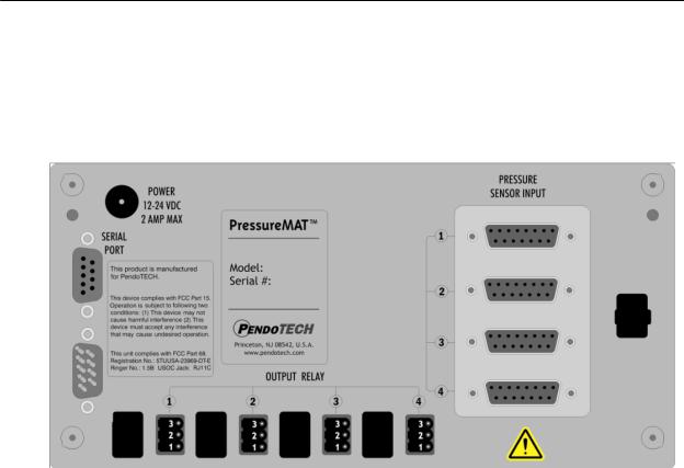
BACK PANEL CONFIGURATIONS:
Two Input Unit (if two relays for each channel, 4-20mA will be labeled OUTPUT RELAY):
Three Input Unit:
Page 6/29
PressureMAT User Guide
Revision 0
Four Input Unit (4R shown, if 4A, OUTPUT RELAY is labeled OUTPUT 4-20mA):
Page 7/29
PressureMAT User Guide
Revision 0
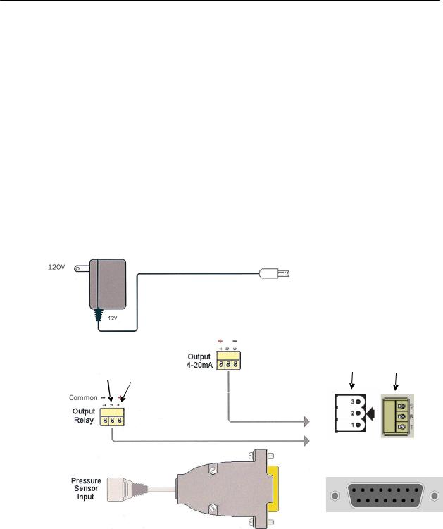
CONNECTIONS:
The external connections to the back panel are as shown below.
1.POWER SUPPLY connected to the power inlet connector
2.The PRESSURE SENSOR INPUTS connected via the DB15 connector
3.The OUTPUT RELAY:
a.NORMALLY OPENwired to terminals S and T via supplied connector (will switch to CLOSED position with alarm condition)
b.NORMALLY CLOSEDwired to terminals R and T via supplied connector (will switch to OPEN position with alarm condition)
c.POWER REMOVEDOPEN (S and T position) is the condition for relay(s)
4.The 4-20mA ANALOG OUTPUTS are wired to terminals S and T via supplied connector as shown.
External Cable Connections to Back Panel
|
|
|
|
|
|
|
|
|
|
|
|
|
|
|
|
|
|
|
|
|
|
|
|
|
|
|
|
|
|
|
|
|
|
|
|
|
Wire here |
|
|
|
|
Wire here |
||
|
for |
|
|
|
|
for |
||
|
Normally |
|
|
|
|
Normally |
||
|
CLOSED |
|
|
|
|
OPEN |
||
|
|
|
|
|
|
|
|
|
|
|
|
|
|
|
|
|
|
|
|
|
|
|
|
|
|
|
|
|
|
|
|
|
|
|
|
To Power Inlet Connector
___________________
Panel Connector
_____________________
To Pressure Sensor Inputs (DB15)
Page 8/29

PressureMAT User Guide
Revision 0
1.2.2.Specifications
Control System Component |
Specifications |
Enclosure |
H x W x D: 7.86” x 4.47” x 2.25” |
|
(19.96 x 11.35 x 5.72 cm) |
|
Approx: 1.43 lbs. (0.65 kgs) |
|
Material: ABS Plastic |
|
Panel/wall mount optional |
|
NEMA 4X front panel |
Environmental |
Temperature: 0–55° C (32–132° F) |
|
Humidity: 0–95% RH non-condensing, Shipping/Storage: |
|
–20° to +85° C |
|
(warm up to rated accuracy = 6 min.) |
Keypad |
8 button keypad with LEXAN® overlay |
Display |
8 line LCD backlit bluepsi as XX.X and bar as X.XX |
Power Inlet |
2.5 mm Circular Power Jack (center post positive) |
|
12-24 Volts DC |
|
4 Watts |
|
(powered by supplied appropriate wall supply) |
Pressure Sensor Inputs |
Configured for PendoTECH Single Use Pressure Sensors* |
|
(See Appendix B) |
|
Connector on reusable cable: DB15 |
Relay Output |
Specifications for relay used for the alarm output: |
|
∙ Normally OPEN or CLOSED via wiring |
|
∙ 28 Volt AC/DC Maximum |
|
∙ 1 amp closure, 2 amps maximum current |
|
∙ 20 mS max turn on/off time |
|
∙ Screw terminal connector |
Analog Outputs (4-20 mA) |
Screw terminal connector |
|
4-20mA Range: -10 to 75 psi (-0.689 bar to 5.171 bar) |
|
Accuracy: 0.1% of full scale |
|
Sourcing w/Maximum Load: 400 Ohms |
|
Load Impedance: Zero Ohm minimum resistance, |
|
20 mAmp maximum output (even if pressure exceeds 5.17 |
|
bar) |
Regulatory Compliances |
CE Mark EN61326-1 |
|
FCC Part 15 Class B verified |
|
FCC Part 68 5TUUSA-23969-DT-E |
* See Appendix B for important information on this product LEXAN® is a registered trademark of General Electric Company
Page 9/29
 Loading...